

Page 1
Debris Blower
Groundsmaster) 4000–D
Model No. 30425—Serial No. 220000001 and Up
Form No. 3326–246 Rev B
Operator’s Manual
English (EN)
Page 2

Contents
Introduction
Introduction 2. . . . . . . . . . . . . . . . . . . . . . . . . . . . . . . . .
Safety 3. . . . . . . . . . . . . . . . . . . . . . . . . . . . . . . . . . . . . .
Before Operating 3. . . . . . . . . . . . . . . . . . . . . . . . . .
While Operating 3. . . . . . . . . . . . . . . . . . . . . . . . . . .
Maintenance 3. . . . . . . . . . . . . . . . . . . . . . . . . . . . . .
Sound Pressure Level 4. . . . . . . . . . . . . . . . . . . . . . .
Sound Power Level 4. . . . . . . . . . . . . . . . . . . . . . . .
Vibration Level 4. . . . . . . . . . . . . . . . . . . . . . . . . . . .
Safety and Instruction Decals 5. . . . . . . . . . . . . . . . .
Specifications 6. . . . . . . . . . . . . . . . . . . . . . . . . . . . . . . .
General Specifications 6. . . . . . . . . . . . . . . . . . . . .
Optional Equipment 6. . . . . . . . . . . . . . . . . . . . . . . .
Setup 7. . . . . . . . . . . . . . . . . . . . . . . . . . . . . . . . . . . . . .
Remove Front Cutting Unit 8. . . . . . . . . . . . . . . . . .
Mount Arm Assemblies 9. . . . . . . . . . . . . . . . . . . . .
Mount Bumper Assembly 9. . . . . . . . . . . . . . . . . . .
Install Handle Assembly 9. . . . . . . . . . . . . . . . . . . .
Install Linkage Rod 10. . . . . . . . . . . . . . . . . . . . . . . .
Mount Blower To Traction Unit 10. . . . . . . . . . . . . . .
Install Hydraulic Motor To Blower 11. . . . . . . . . . . .
Grease Blower 11. . . . . . . . . . . . . . . . . . . . . . . . . . . .
Operation 12. . . . . . . . . . . . . . . . . . . . . . . . . . . . . . . . . . .
Operating Tips 12. . . . . . . . . . . . . . . . . . . . . . . . . . . .
Adjusting Castor Wheels 12. . . . . . . . . . . . . . . . . . . .
Adjust Discharge Opening 13. . . . . . . . . . . . . . . . . . .
Adjust Discharge Direction 13. . . . . . . . . . . . . . . . . .
Maintenance 14. . . . . . . . . . . . . . . . . . . . . . . . . . . . . . . . .
Greasing the Blower 14. . . . . . . . . . . . . . . . . . . . . . . .
Disconnect Blower From Traction Unit 14. . . . . . . . .
Servicing Bumper Bushings 14. . . . . . . . . . . . . . . . . .
Servicing Castor Wheel And Bearing 15. . . . . . . . . .
Alignment Tool 15. . . . . . . . . . . . . . . . . . . . . . . . . . .
The Toro General Commercial Products Warranty 16. . .
Page
Read this manual carefully to learn how to operate and
maintain your product properly. The information in this
manual can help you and others avoid injury and product
damage. Although Toro designs and produces safe
products, you are responsible for operating the product
properly and safely.
Whenever you need service, genuine Toro parts, or
additional information, contact an Authorized Service
Dealer or Toro Customer Service and have the model and
serial numbers of your product ready. The two numbers are
stamped on a plate which is located on the blower housing.
Write the product model and serial numbers in the space
below:
Model No.
Serial No.
This manual identifies potential hazards and has special
safety messages that help you and others avoid personal
injury and even death. Danger, Warning, and Caution are
signal words used to identify the level of hazard. However,
regardless of the hazard, be extremely careful.
Danger signals an extreme hazard that will cause serious
injury or death if you do not follow the recommended
precautions.
Warning signals a hazard that may cause serious injury or
death if you do not follow the recommended precautions.
Caution signals a hazard that may cause minor or moderate
injury if you do not follow the recommended precautions.
This manual uses two other words to highlight information.
Important calls attention to special mechanical
information and Note: emphasizes general information
worthy of special attention.
W 2002 by The Toro Company
8111 Lyndale Avenue South
Bloomington, MN 55420-1196
All Rights Reserved
Printed in the USA
2
Page 3

Safety
Hazard control and accident prevention are dependent
upon the awareness, concern, and proper training of the
personnel involved in the operation, transport,
maintenance, and storage of the machine. Improper use
or maintenance of the machine can result in injury or
death. To reduce the potential for injury or death,
comply with the following safety instructions.
Before Operating
• Read and understand the contents of this Operator’s
Manual before operating the machine. Become familiar
with all of the controls and know how to stop quickly. A
free replacement manual is available by sending the
complete Model and Serial Number to The Toro
Company, 8111 Lyndale Avenue South, Bloomington,
Minnesota 55420-1196.
• Never allow children to operate the machine. Do not
allow adults to operate machine without proper
instruction. Only trained operators who have read this
manual should operate this machine.
• Never operate the machine when under the influence of
drugs or alcohol.
• Keep all bystanders away from the operating area.
• Keep all shields and safety devices in place. If a shield,
safety device, or decal is illegible or damaged, repair or
replace it before operation is commenced. Also tighten
any loose nuts, bolts, and screws to ensure that the
machine is in safe operating condition.
• Do not operate the machine while wearing sandals,
tennis shoes, sneakers, or shorts. Also, do not wear
loose fitting clothing which could get caught in moving
parts. Always wear long pants and substantial shoes.
Wearing safety glasses, safety shoes, and a helmet is
advisable and required by some local ordinances and
insurance regulations.
While Operating
• This product may exceed noise levels of 85 dB(A) at
the operator position. Ear protectors are recommended
for prolonged exposure to reduce the potential of
permanent hearing damage.
• Optional attachments may impact the operating
characteristics of the traction unit. For example, slopes
that have been mowed with cutting decks may be unsafe
to travel on with a narrow attachment, such as a blower,
due to the loss of support and stability provided by the
width of the decks. Further, the decks may have
prevented the traction unit from coming too close to
holes, dips, drop offs, obstacles and uneven terrain
which may cause a roll over. Use extra caution when
operating a traction unit with a blower attached in place
of mowing decks.
• Rollover protection and seat belts are recommended for
use on hillsides.
• Using the machine demands attention. To prevent loss
of control:
– Operate only in daylight or when there is good
artificial light.
– Drive slowly and watch for holes or other hidden
hazards.
– Do not drive close to a sand trap, ditch, creek, or
other hazard.
– Reduce your speed when making sharp turns and
when turning on hillsides.
– Avoid sudden starts and stops.
– Before backing up, look to the rear and ensure that
no one is behind the machine.
– Watch out for traffic when near or crossing roads.
Always yield the right-of-way.
• Stay away from the discharge opening when the
machine is operating. Keep all bystanders away from
the discharge opening and don’t direct discharge toward
bystanders.
• If the engine stalls or the machine loses headway and
cannot make it to the top of a slope, do not turn the
machine around. Always back slowly straight down the
slope.
• Do not take an injury risk! When a person or pet
appears unexpectedly in or near the operating area, stop
operation. Careless operation, combined with terrain
angles, ricochets, or improperly positioned guards can
lead to thrown object injuries. Do not resume operation
until the area is cleared.
• Lower the blower to the ground and remove the key
from the ignition switch whenever the machine is left
unattended.
Maintenance
• Remove the key from the ignition switch to prevent
accidental starting of the engine when servicing,
adjusting, or storing the machine.
• Perform only those maintenance instructions described
in this manual. If major repairs are ever needed or
assistance is desired, contact an Authorized Toro
Distributor.
3
Page 4

• Be sure that the machine is in safe operating condition
by keeping nuts, bolts, and screws tight. Check all bolts
and nuts frequently to be sure that they are tightened to
specification.
• To ensure optimum performance and safety, always
purchase genuine Toro replacement parts and
accessories to keep the machine all Toro. Never use
“will-fit” replacement parts and accessories made by
other manufacturers. Look for the Toro logo to ensure
genuineness. Using unapproved replacement parts and
accessories could void the warranty.
Sound Pressure Level
This unit has an equivalent continuous A–weighted sound
pressure level at the operator ear of 91 dBA, based on
measurements of identical machines per Directive
98/37/EC and amendments.
Sound Power Level
This unit has a guaranteed sound power level of
111 dBA/1 pW, based on measurements of identical
machines per Directive 2000/14/EC and amendments.
Vibration Level
Hand-Arm
This unit does not exceed a vibration level of 2.5 m/s2 at
the hands based on measurements of identical machines per
ISO 5349 procedures.
Whole Body
This unit does not exceed a vibration level of .5 m/s2 at the
posterior based on measurements of identical machines per
ISO 2631 procedures.
4
Page 5
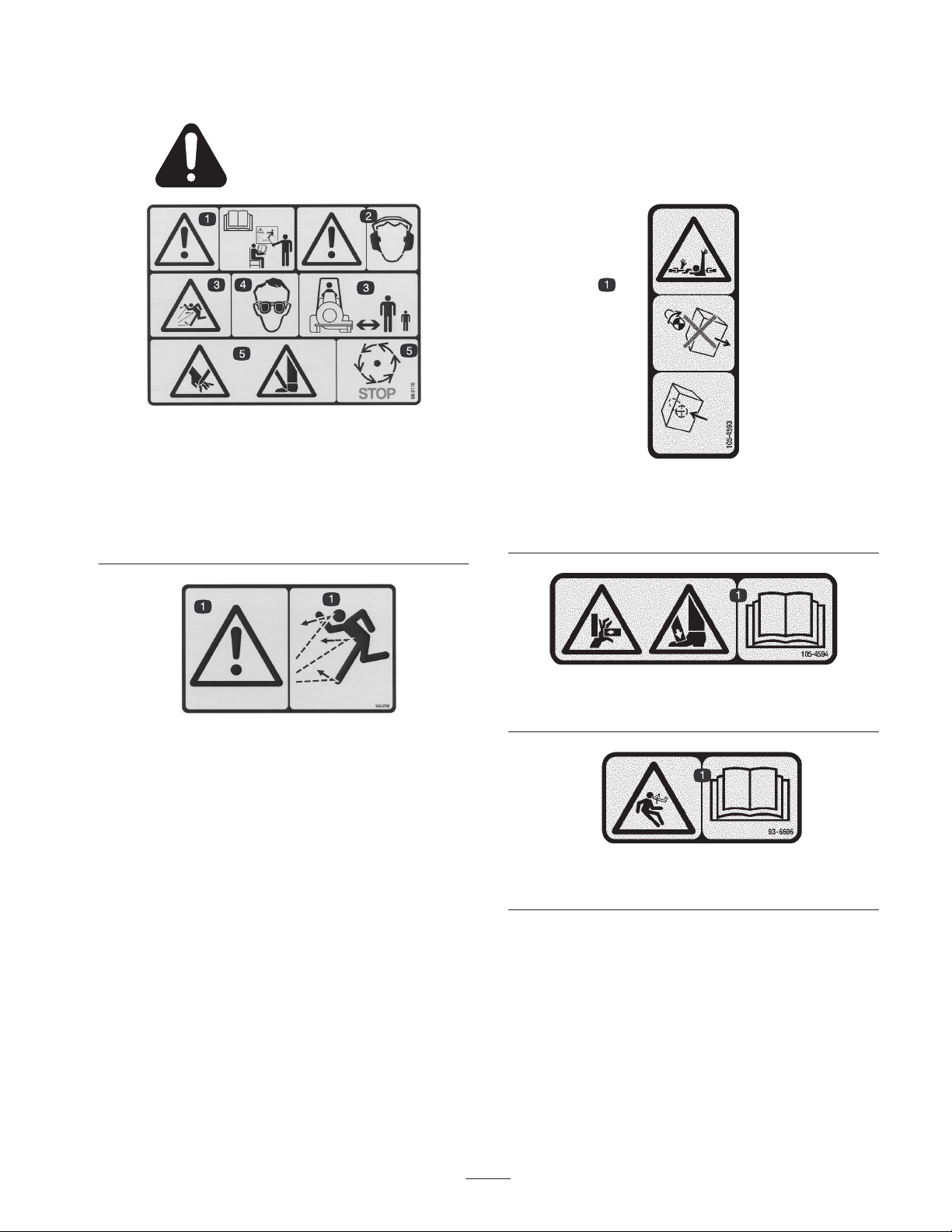
Safety and Instruction Decals
Safety decals and instructions are easily visible to the operator and are located near any area
of potential danger. Replace any decal that is damaged or lost.
98-3110
1. Danger–See Operator’s
Manual
2. Danger–Wear ear
protection
3. Thrown object
hazard–Keep bystanders
away.
4. Always wear eye
protection
5. Cutting hazard to hands
or feet–wait until all
machine components
have stopped before
touching them.
105-4593
1. Entanglement hazard, PTO shaft—do not operate the machine
with the shields or guards removed; always keep the shields
and guards in place.
105–0708
1. Danger–Blown object hazard–Keep bystanders away from
chute outlet.
105-4594
1. Crushing hazard, hand and foot—read the Operator’s Manual.
93-6696
1. Stored energy hazard—read the Operator’s Manual.
5
Page 6

Specifications
General Specifications
Fan Output
Fan Speed 2575 RPM
Outlet Area Adjustable outlet opening, 39 to 70 square inches
Directional Control 90 degree outlet deflector operated from seat
Castor Wheels Two 8 x 3–1/2 inch solid rubber tires
Height Adjustment 4 to 6–1/2 inches Adjustment is with 1/2 inch spacers and holes in castor fork
Ground Clearance–Transport 11–1/4 inches
Fan
Fan Housing
Drive
Weight: 321 lbs.
Note: Specifications and design subject to change without notice.
5000 CFM
165 MPH
Backward curved, cast aluminium fan. 12 blades per side, 21 inch outside diameter,
6–3/8 inch width, weight 34 lbs.
10 gauge steel face plates welded to 14 gauge wrapper. Eight degree increase scroll form
cutoff.
Gear motor directly coupled to fan shaft via Rotex coupling. 1–1/4 inch diameter fan shaft
rotates on two greaseable ball bearings.
Optional Equipment
180 Degree Deflector Kit Part No. 95–5909
6
Page 7

Setup
Note: Use this chart as a checklist to ensure that all parts have been received. Without these parts, total setup cannot be
completed.
Description
Blower Housing Assembly 1
Arm Assembly – R.H.
Arm Assembly – L.H.
Capscrew
Flatwasher
Locknut
Bumper Assembly
Capscrew
Flatwasher
Locknut
Handle Assembly
Capscrew
Flatwasher
Linkage Rod
Flatwasher
Cotter Pin
Capscrew
Flatwasher
Locknut
Clamping Plate
Reinforcing Plate
Capscrew
Flatwasher
Flange Nut
Qty. Use
1
1
4
4
4
1
8
8
8
1
2
2
1
2
2
4
8
4
2
2
4
4
4
Mount to blower assembly.
Mount to arm assemblies.
Mount to blower housing.
Mount to handle assembly and deflector
assembly.
Mount blower to traction unit.
Cable Tie 1 Secure hydraulic hoses to blower housing
Operator’s Manual 1 Read before operating the machine.
Parts Catalog 1
Registration card 1 Fill out and return to Toro.
Declaration of Conformity 1
7
Page 8

Note: Determine the left and right sides of the machine
from the normal operating position.
Remove Front Cutting Unit
1. Position machine on a level surface, lower mower decks
to the floor, engage parking brake, be sure traction
pedal is in neutral position, PTO lever in OFF position,
shut engine OFF and remove key from switch.
2. Remove bolts securing hydraulic motor to deck (Fig. 1).
Lift motor off deck and lay it on a clean, out of the way,
surface. Do not damage aluminium coupler.
2
4. Remove hair pin cotters and clevis pins securing
height-of-cut chains to rear of deck (Fig. 3). Retain hair
pin cotters and clevis pins for re–installation of front
deck
1
2
Figure 3
1. Height of cut chain 2. Clevis pin & hairpin cotter
2
1
Figure 1
1. Hydraulic motor 2. Mounting bolts
3. Remove spider from inside pulley coupler. Inspect for
wear and replace if worn. Retain for installation on
blower (Fig. 2).
Note: Inspect motor spider hub for wear and replace if
worn (Fig. 2).
2
3
1
Figure 2
1. Spider
2. Motor spider hub
3. Pulley coupler
5. Remove bolts, washers and locknuts securing each lift
arm ball joint mount to cutting unit castor arm tube
(Fig. 4).
1
1
Figure 4
1. Lift arm ball joint mount (2)
6. Move mower deck away from traction unit.
8
Page 9

Mount Arm Assemblies
1. Align the rear set of mounting holes in each lift arm
with holes in the blower housing mounting brackets.
Position lift arms as shown in figure 5.
2. Loosely secure each lift arm to mounting bracket with
(2) capscrews, flatwashers and locknuts. Do not tighten
locknuts.
2
3
1
Figure 6
1. Bumper assembly
Install Handle Assembly
1. Position handle mounting tube between tabs on top of
blower housing (Fig. 7).
Note: When mounting a debris blower on a traction unit
equipped with a cab, rotate handle 180_ when installing.
2. Secure each end of tube to a housing tab with a
capscrew and flatwasher.
1
Figure 5
1. Lift arm
2. Blower housing
3. Mounting brackets
Mount Bumper Assembly
1. While aligning mounting holes, position bumper
assembly onto lift arms (Fig. 6).
2. Loosely secure bumper assembly to each lift arm with
(4) capscrews, flatwashers and locknuts.
2
1
Figure 7
1. Handle assembly 2. Handle grip
3. Insert handle grip onto handle (Fig. 7).
9
Page 10

Install Linkage Rod
1. Insert front end of linkage rod through hole in handle
assembly while hooking rear end of linkage rod thru
hole in rear tab on deflector assembly (Fig. 8).
Note: When mounting a debris blower on a traction unit
equipped with a cab, rotate handle 180_ and use front tab
on deflector for rod installation.
2. Secure each end of rod with a flatwasher and cotter pin.
2
1
3
1
2
Figure 9
1. Manifold block 2. Orifice
Mount Blower To Traction Unit
Figure 8
1. Linkage rod
2. Handle assembly
3. Rear tab
Replace PTO Manifold Orifice
Note: On traction units that have a gold colored PTO
manifold (Fig. 9) orifice must be removed and replaced. If
PTO manifold is silver, orifice does not need to be
replaced.
1. Using a 1/8” Allen wrench, remove orifice plug from
MR port of front PTO manifold (Fig. 9).
2. Order plug Part No. 3246–17 from your Toro distributor
and install into MR port of manifold with a 5/32” Allen
wrench.
1. Move traction unit up to blower until lift arms are
aligned with blower arm assemblies (Fig. 10).
3
1
2
4
Figure 10
1. Lift arm ball joint mount
2. Arm assembly
3. Clamping plate
4. Reinforcing plate
10
Page 11

2. Mount each lift arm ball joint mount to each side of
blower arm assembly with (2) capscrews (4) flatwashers
and (2) locknuts. Position fasteners as shown in
figure 10.
3. Mount each lift arm to top of each blower arm assembly
with (2) capscrews (2) flatwashers, clamping plate,
reinforcing plate and (2) locknuts. Position components
as shown in figure 10.
2
3
4. Tighten all blower and lift arm mounting fasteners.
Install Hydraulic Motor To
Blower
1. Remove (2) socket head screws and flange nuts
securing alignment tool to motor mount (Fig. 11).
4
3
1
2
Figure 11
1. Alignment tool
2. Motor mount
3. Mount bracket
4. Bearing mount bracket
1
2
Figure 12
1. Hydraulic motor
2. Large hoses
3. Small hose
4. Install hydraulic motor and spider to blower mount with
(2) socket head screws and flange nuts as shown in
figure 13.
Note: Motor to be installed with hoses exiting to the left
side of blower.
2
1
Note: Retain alignment tool for re–aligning components if
ever disassembled.
2. Remove the two larger diameter hydraulic hoses from
hydraulic motor and loosely install in opposite ports
(Fig. 12).
Note: If hoses are not reversed, blower will rotate
backwards.
3. Loosen the small diameter hydraulic hose to motor.
3
Figure 13
1. Hydraulic motor
2. Spider
3. Blower mount
5. Tighten and torque hydraulic hoses as follows:
• Torque (2) larger hoses to 43–48 ft./lb.
• Torque smaller hose to 23 ft./lb.
11
Page 12

6. Secure hydraulic hoses to blower housing with wire tie
(Fig. 14).
2
Operation
Note: Determine the left and right sides of the machine
from the normal operating position.
Operating Tips
Warning
1
Figure 14
1. Hydraulic hoses 2. Wire tie
Note: Hoses must not contact sharp edges or moving parts
and must be free of twists.
Grease Blower
Before the Debris Blower is operated, it must be greased to
assure proper lubricating characteristics: refer to
Lubrication section of manual. Failure to properly grease
the unit will result in premature failure of critical parts.
Discharged air has considerable force and could
cause injury or loss of footing.
• Stay away from the discharge opening when the
machine is operating.
• Keep bystanders away from the discharge
opening when the machine is running.
1. Practice blowing material. It is advisable to blow the
same direction the wind is blowing to prevent material
from blowing back into the cleared area.
Adjusting Castor Wheels
The castor wheel height is adjustable from 4 to 6–1/2
inches in 1/2 inch increments by adding or removing an
equal amount of spacers from each castor wheel. Adjust
castor height for different turf conditions.
1. Start engine and raise blower. Stop engine after blower
unit is raised.
2. Remove locking cap securing castor spindle to bumper
(Fig. 15).
3. Move desired amount of spacers (Fig. 15) to top or
bottom of bumper. Make sure spacers are equal on both
castor wheels.
4. Install locking cap and lower blower.
12
Page 13

1
1. Locking cap
2. Spacers
3
3
Figure 15
3. Thrust washers
2
3
2
1
Figure 16
1. Discharge opening
deflector screw
2. Discharge direction
deflector
3. Handle assembly
Adjust Discharge Opening
The discharge opening (Fig. 16) is adjustable to increase or
decrease air output velocity and volume. Decreasing
discharge opening size will increase velocity.
1. Loosen discharge opening deflector mounting screws.
2. Pivot deflector to desired opening.
3. Tighten mounting screws.
Adjust Discharge Direction
Lower deflector assembly in front of discharge opening to
change from side discharge to front discharge (Fig. 16).
1. Pivot handle assembly to the left to lower deflector
assembly over opening, directing discharge forward.
2. Pivot handle assembly to the right to raise deflector
from discharge opening, allowing side discharge.
13
Page 14

Maintenance
Note: Determine the left and right sides of the machine
from the normal operating position.
Greasing the Blower
The debris blower must be lubricated regularly. If machine
is operated under normal conditions, lubricate castor and
fan bearings and bushings with No. 2 general purpose
lithium base grease or molybdenum base grease, after every
8 hours of operation or daily, whichever comes first.
Lubricate fittings immediately after every washing,
regardless of the interval listed.
1. The debris blower has (4) bearings and bushings that
must be lubricated. The lubrication points are: castor
shaft bushings (2) and fan shaft bearings (2) (Fig. 17).
(2)
1
2
Figure 18
1. Stand 2. Snapper pin
3. Lower blower to the floor or any stable surface.
4. Remove cable tie securing hydraulic hoses to blower
housing.
5. Remove (2) socket head screws and flange nuts
securing hydraulic motor and spider to blower mount
(Fig. 13).
6. Remove (2) capscrews (4) flatwashers, clamping plate,
reinforcing plate and (2) locknuts securing each lift arm
to top of each blower arm assembly (Fig. 10).
7. Remove (2) capscrews (4) flatwashers and (2) locknuts
securing each lift arm ball joint mount to each side of
blower arm assembly (Fig. 10).
(2)
Figure 17
Disconnect Blower From
Traction Unit
Note: Implements are heavy and may require two people to
handle.
1. Remove snapper pin securing stand to tube on blower
(Fig. 18).
2. Lower stand. Re–install pin through upper set of holes
in stand and tube. Secure pin.
8. Stay clear of lift arms and move traction unit away from
blower.
Servicing Bumper Bushings
After many hours of operation, the bushings pressed into
the top and bottom of the bumper will wear. To check the
bushings, move castor fork fore and aft and from side to
side. If castor spindle is loose in the bushings, bushings are
worn and must be replaced.
1. Start traction unit and raise blower to highest possible
position and turn off engine. Block up blower frame so
it cannot accidentally fall.
2. Remove locking cap and thrust washers from top of
castor spindle.
3. Pull castor spindle out of bumper. Allow thrust washers
to remain on bottom of spindle.
14
Page 15

4. Insert pin punch into top or bottom of bumper and drive
bushing out of tube (Fig. 19). Also drive other bushing
out of bumper. Clean inside of bumper to remove any
dirt.
2
1
1
2
2
Figure 19
1. Bumper 2. Bushing
5. Apply grease to inside and outside of new bushings.
Using a hammer and flat plate, drive bushings into
bumper.
6. Inspect castor shaft for wear and replace if damaged.
7. Push castor shaft through bushings and bumper. Slide
spacers onto shaft and secure with locking cap.
Servicing Castor Wheel And
Bearing
The castor wheel rotates on a high–quality roller bearing
and is supported by a spanner bushing. Even after many
hours of use, provided that the bearing was kept well
lubricated, bearing wear will be minimal. However, failure
to keep bearing lubricated will cause rapid wear. A wobbly
castor wheel usually indicates a worn bearing.
1
Figure 20
1. Outer bearing 2. Inner bearing
Alignment Tool
If motor mount components are ever disassembled and
have to be realigned, proceed as follows:
• Loosen (4) screws and nuts securing motor mount to
mount bracket (Fig. 21).
• Loosen (4) screws, washers and nuts securing mount
bracket to bearing mount bracket (Fig. 21).
• Insert alignment tool into motor mount and secure
with (2) socket head screws and flange nuts
(Fig. 21).
• Tighten all fasteners securing motor mount, mount
bracket and bearing mount bracket.
4
1. Remove locknut from capscrew holding castor wheel
assembly in castor fork. Grasp castor wheel and slide
capscrew out of fork.
2. Remove outer bearing from wheel hub and allow inner
bearing to fall out (Fig. 20). Remove outer bearing from
opposite side of wheel hub.
3. Check the bearings and inside of wheel hub for wear.
Replace defective parts as required.
4. To assemble the castor wheel, push outer bearing into
wheel hub. Slide inner bearing into wheel hub. Push
other bearing into open end of wheel hub to captivate
the inner bearing inside the wheel hub.
5. Install castor wheel assembly between castor forks and
secure in place with capscrew and locknut.
3
1
1. Alignment tool
2. Motor mount
15
2
Figure 21
3. Mount bracket
4. Bearing mount bracket
Page 16

The Toro General Commercial Products Warranty
A Two-Year Limited Warranty
Conditions and Products Covered
The Toro Company and its affiliate, Toro Warranty Company,
pursuant to an agreement between them, jointly warrant your Toro
Commercial Product (“Product”) to be free from defects in
materials or workmanship for two years or 1500 operational
hours*, whichever occurs first. Where a warrantable condition
exists, we will repair the Product at no cost to you including
diagnosis, labor, parts, and transportation. This warranty begins
on the date the Product is delivered to the original retail purchaser.
* Product equipped with hour meter
Instructions for Obtaining Warranty Service
You are responsible for notifying the Commercial Products
Distributor or Authorized Commercial Products Dealer from whom
you purchased the Product as soon as you believe a warrantable
condition exists.
If you need help locating a Commercial Products Distributor or
Authorized Dealer, or if you have questions regarding your
warranty rights or responsibilities, you may contact us at:
Toro Commercial Products Service Department
Toro Warranty Company
8111 Lyndale Avenue South
Bloomington, MN 55420-1196
952-888-8801 or 800-982-2740
E-mail: commercial.service@toro.com
Owner Responsibilities
As the Product owner, you are responsible for required maintenance and adjustments stated in your operator’s manual. Failure
to perform required maintenance and adjustments can be grounds
for disallowing a warranty claim.
Items and Conditions Not Covered
Not all product failures or malfunctions that occur during the
warranty period are defects in materials or workmanship. This
express warranty does not cover the following:
• Product failures which result from the use of non-Toro
replacement parts, or from installation and use of add-on,
modified, or unapproved accessories
• Product failures which result from failure to perform required
maintenance and/or adjustments
• Product failures which result from operating the Product in an
abusive, negligent or reckless manner
• Parts subject to consumption through use unless found to be
defective. Examples of parts which are consumed, or used up,
during normal Product operation include, but are not limited to,
blades, reels, bedknives, tines, spark plugs, castor wheels,
tires, filters, belts, and certain sprayer components such as
diaphragms, nozzles, and check valves, etc.
• Failures caused by outside influence. Items considered to be
outside influence include, but are not limited to, weather,
storage practices, contamination, use of unapproved coolants,
lubricants, additives, or chemicals, etc.
• Normal “wear and tear” items. Normal “wear and tear” includes,
but is not limited to, damage to seats due to wear or abrasion,
worn painted surfaces, scratched decals or windows, etc.
Parts
Parts scheduled for replacement as required maintenance are
warranted for the period of time up to the scheduled replacement
time for that part.
Parts replaced under this warranty become the property of Toro.
Toro will make the final decision whether to repair any existing part
or assembly or replace it. Toro may use factory remanufactured
parts rather than new parts for some warranty repairs.
General Conditions
Repair by an Authorized Toro Distributor or Dealer is your sole
remedy under this warranty.
Neither The Toro Company nor Toro Warranty Company is
liable for indirect, incidental or consequential damages in
connection with the use of the Toro Products covered by this
warranty, including any cost or expense of providing substitute equipment or service during reasonable periods of
malfunction or non-use pending completion of repairs under
this warranty. Except for the Emissions warranty referenced
below, if applicable, there is no other express warranty. All
implied warranties of merchantability and fitness for use are
limited to the duration of this express warranty.
Some states do not allow exclusions of incidental or consequential
damages, or limitations on how long an implied warranty lasts, so
the above exclusions and limitations may not apply to you.
This warranty gives you specific legal rights, and you may also
have other rights which vary from state to state.
Note regarding engine warranty: The Emissions Control System
on your Product may be covered by a separate warranty meeting
requirements established by the U.S. Environmental Protection
Agency (EPA) and/or the California Air Resources Board (CARB).
The hour limitations set forth above do not apply to the Emissions
Control System Warranty. Refer to the Engine Emission Control
Warranty Statement printed in your operator’s manual or contained in the engine manufacturer’s documentation for details.
Countries Other than the United States or Canada
Customers who have purchased Toro products exported from the United States or Canada should contact their Toro Distributor (Dealer)
to obtain guarantee policies for your country, province, or state. If for any reason you are dissatisfied with your Distributor’s service or
have difficulty obtaining guarantee information, contact the Toro importer. If all other remedies fail, you may contact us at Toro Warranty
Company.
Part No. 374-0031 Rev. C
 Loading...