

Page 1
FormNo.3360-356RevB
Groundsmaster
®
4100-DTraction
Unit
ModelNo.30413—SerialNo.2900000001andUp
Registeratwww.T oro.com.OriginalInstructions(EN)
Page 2

Warning
CALIFORNIA
Proposition65Warning
Dieselengineexhaustandsomeofits
constituentsareknowntotheStateof
Californiatocausecancer,birthdefects,
andotherreproductiveharm.
Becauseinsomeareastherearelocal,state,orfederal
regulationsrequiringthatasparkarresterbeusedonthe
engineofthismachine,asparkarresterisincorporated
withthemuferassembly.
GenuineTorosparkarrestersareapprovedbytheUSDA
ForestryService.
Important:Thisengineisequippedwithaspark
arrestermufer.ItisaviolationofCaliforniaPublic
ResourceCodeSection4442touseoroperate
theengineonanyforest-covered,brush-covered,
orgrass-coveredlandwithoutasparkarrester
mufermaintainedinworkingorder,ortheengine
constricted,equipped,andmaintainedforthe
preventionofre.Otherstatesorfederalareasmay
havesimilarlaws.
Figure1
1.Safetyalertsymbol
Thismanualuses2otherwordstohighlightinformation.
Importantcallsattentiontospecialmechanical
informationandNoteemphasizesgeneralinformation
worthyofspecialattention.
Introduction
Readthisinformationcarefullytolearnhowtooperate
andmaintainyourproductproperlyandtoavoidinjury
andproductdamage.Youareresponsibleforoperating
theproductproperlyandsafely.
YoumaycontactTorodirectlyatwww .Toro.comfor
productandaccessoryinformation,helpndinga
dealer,ortoregisteryourproduct.
Wheneveryouneedservice,genuineToroparts,or
additionalinformation,contactanAuthorizedService
DealerorToroCustomerServiceandhavethemodel
andserialnumbersofyourproductready.Writethe
numbersinthespaceprovided.
ModelNo.
SerialNo.
Thismanualidentiespotentialhazardsandhas
safetymessagesidentiedbythesafetyalertsymbol
(Figure1),whichsignalsahazardthatmaycauseserious
injuryordeathifyoudonotfollowtherecommended
precautions.
©2008—TheToro®Company
8111LyndaleAvenueSouth
Bloomington,MN55420
Contactusatwww.Toro.com.
2
PrintedintheUSA.
AllRightsReserved
Page 3

Contents
Introduction.................................................................2
Safety...........................................................................4
SafeOperatingPractices.......................................4
ToroMowerSafety...............................................6
SoundPressureLevel...........................................7
SoundPowerLevel...............................................7
VibrationLevel.....................................................7
SafetyandInstructionalDecals.............................8
Setup..........................................................................14
1GreasingtheMachine......................................14
2ReplacingtheWarningDecal............................14
3ReadingtheManualsandReviewthe
TrainingMaterials...........................................14
ProductOverview......................................................15
Controls.............................................................15
Specications.....................................................17
Attachments/Accessories...................................17
Operation...................................................................18
BeforeOperating................................................18
StartingandStoppingtheEngine........................27
EngineCoolingFanOperation...........................27
CheckingtheInterlockSwitches.........................28
PushingorTowingtheMachine..........................28
JackingPoints.....................................................29
TieDowns.........................................................29
OperatingCharacteristics...................................29
OperatingTips...................................................30
Maintenance...............................................................32
RecommendedMaintenanceSchedule(s)................32
ServiceIntervalChart.........................................33
Lubrication.............................................................33
GreasingtheBearingsandBushings....................33
EngineMaintenance...............................................37
AirCleanerMaintenance....................................37
ServicingtheEngineOilandFilter......................38
FuelSystemMaintenance.......................................39
ServicingtheFuelSystem...................................39
BleedingAirfromtheInjectors...........................39
ElectricalSystemMaintenance................................40
Activating,Charging,andConnectingthe
Battery...........................................................40
BatteryCare.......................................................40
Fuses..................................................................41
DriveSystemMaintenance.....................................42
ChangingthePlanetaryGearDrive
Oil..................................................................42
ChangingtheRearAxleLubricant.......................43
CheckingtheRearWheelToe-In.........................44
ChangingtheFrontTires....................................44
CoolingSystemMaintenance..................................44
ServicingtheEngineCoolingSystem..................44
BrakeMaintenance.................................................45
AdjustingtheServiceBrakes...............................45
BeltMaintenance....................................................46
ServicingtheAlternatorBelt...............................46
Re-tensioningtheBladeDriveBelts....................46
ReplacingtheBladeDriveBelt............................46
ControlsSystemMaintenance.................................47
AdjustingtheThrottleCable...............................47
AdjustingtheTractionPedalLinkage..................47
HydraulicSystemMaintenance...............................48
ChangingtheHydraulicFluid.............................48
ReplacingtheHydraulicFilters...........................49
CheckingtheHydraulicLinesandHoses.............49
AdjustingtheCounterbalancePressure...............49
AdjustingtheCuttingUnitFlowControl.............49
MowerMaintenance...............................................50
Pivoting(Tilting)theFrontCuttingUnit
Upright..........................................................50
PivotingtheFrontCuttingUnitDown................51
AdjustingtheCuttingUnitPitch.........................51
ServicingtheCastorArmBushings.....................52
ServicingtheCastorWheelsandBearings............52
ReplacingtheCuttingUnitHingeCovers............53
BladeMaintenance.................................................53
CheckingforaBentBlade...................................53
RemovingandInstallingtheCutter
Blade(s)..........................................................53
InspectingandSharpeningtheCutter
Blade(s)..........................................................54
CorrectingCuttingUnitMismatch......................55
SparkArrestorMaintenance...................................56
ServicingtheSparkArrestorMufer...................56
Storage.......................................................................57
PreparingforSeasonalStorage............................57
Schematics.................................................................58
3
Page 4

Safety
ThismachinemeetsorexceedsCENstandard
EN836:1997,ISOstandard5395:1990,andANSI
B71.4-2004specicationsineffectatthetimeof
production.
Improperuseormaintenancebytheoperator
orownercanresultininjury.Toreducethe
potentialforinjury,complywiththesesafety
instructionsandalwayspayattentiontothesafety
alertsymbol,whichmeansCaution,Warning,or
Danger—personalsafetyinstruction.Failureto
complywiththeinstructionmayresultinpersonal
injuryordeath.
◊incorrecthitchingandloaddistribution.
•Theowner/usercanpreventandisresponsiblefor
accidentsorinjuriesoccurringtohimselforherself,
otherpeople,orproperty.
Preparation
•Whilemowing,alwayswearsubstantialfootwear,
longtrousers,hardhat,safetyglasses,andhearing
protection.Longhair,looseclothingorjewelrymay
gettangledinmovingparts.Donotoperatethe
equipmentwhenbarefootorwearingopensandals.
•Thoroughlyinspecttheareawheretheequipment
istobeusedandremoveallobjectswhichmaybe
thrownbythemachine.
SafeOperatingPractices
ThefollowinginstructionsarefromtheCENstandard
EN836:1997,ISOstandard5395:1990,andANSI
standardB71.4-2004.
Training
•ReadtheOperator’ sManualandothertrainingmaterial
carefully.Befamiliarwiththecontrols,safetysigns,
andtheproperuseoftheequipment.
•Neverallowchildrenorpeopleunfamiliarwiththese
instructionstousethemower.Localregulationsmay
restricttheageoftheoperator.
•Nevermowwhilepeople,especiallychildren,orpets
arenearby .
•Keepinmindthattheoperatororuserisresponsible
foraccidentsorhazardsoccurringtohimselfor
herself,otherpeople,orproperty.
•Donotcarrypassengers.
•Alldriversandmechanicsshouldseekandobtain
professionalandpracticalinstruction.Theowneris
responsiblefortrainingtheusers.Suchinstruction
shouldemphasize:
–theneedforcareandconcentrationwhen
workingwithride-onmachines;
–controlofaride-onmachineslidingonaslope
willnotberegainedbytheapplicationofthe
brake.Themainreasonsforlossofcontrolare:
◊insufcientwheelgrip;
◊beingdriventoofast;
◊inadequatebraking;
◊thetypeofmachineisunsuitableforitstask;
◊lackofawarenessoftheeffectofground
conditions,especiallyslopes;
•Warningfuelishighlyammable.Takethe
followingprecautions:
–Storefuelincontainersspecicallydesignedfor
thispurpose.
–Refueloutdoorsonlyanddonotsmokewhile
refuelling.
–Addfuelbeforestartingtheengine.Never
removethecapofthefueltankoraddfuelwhile
theengineisrunningorwhentheengineishot.
–Iffuelisspilled,donotattempttostartthe
enginebutmovethemachineawayfromthe
areaofspillageandavoidcreatinganysourceof
ignitionuntilfuelvaporshavedissipated.
–Replaceallfueltankandcontainercapssecurely.
•Replacefaultysilencers/mufers.
•Beforeusing,alwaysvisuallyinspecttoseethatthe
blades,bladebolts,andcuttingassemblyarenot
wornordamaged.Replacewornordamagedblades
andboltsinsetstopreservebalance.
•Onmulti-bladedmachines,takecareasrotatingone
bladecancauseotherbladestorotate.
•Evaluatetheterraintodeterminewhataccessories
andattachmentsareneededtoproperlyand
safelyperformthejob.Onlyuseaccessoriesand
attachmentsapprovedbythemanufacturer.
•Checkthatoperatorspresencecontrols,safety
switches,andshieldsareattachedandfunctioning
properly.Donotoperateunlesstheyarefunctioning
properly.
Operation
•Donotoperatetheengineinaconnedspacewhere
dangerouscarbonmonoxidefumescancollect.
•Mowonlyindaylightoringoodarticiallight.
4
Page 5

•Beforeattemptingtostarttheengine,disengageall
bladeattachmentclutches,shiftintoneutral,and
engagetheparkingbrake.Onlystarttheenginefrom
theoperator’sposition.Useseatbelts.
•Donotusethismachineonslopesgreaterthan15°.
•Rememberthereisnosuchthingasasafeslope.
Travelongrassslopesrequiresparticularcare.To
guardagainstoverturning:
–Donotstoporstartsuddenlywhengoingupor
downhill.
–Engagetheclutchslowly ,alwayskeepthe
machineingear,especiallywhentravelling
downhill.
–Themachinespeedshouldbekeptlowonslopes
andduringtightturns.
–Stayalertforhumpsandhollowsandother
hiddenhazards.
–Nevermowacrossthefaceoftheslope,unless
themachineisdesignedforthatpurpose.
•Stayalertforholesintheterrainandotherhidden
hazards.
•Watchoutfortrafcwhencrossingornearroadways.
•Stopthebladesfromrotatingbeforecrossing
surfacesotherthangrass.
•Whenusinganyattachments,neverdirectdischarge
ofmaterialtowardbystandersnorallowanyonenear
themachinewhileinoperation.
•Neveroperatethemachinewithdamagedguards,
shields,orwithoutsafetyprotectivedevicesinplace.
Besureallinterlocksareattached,adjustedproperly,
andfunctioningproperly .
•Donotchangetheenginegovernorsettingsorover
speedtheengine.Operatingtheengineatexcessive
speedmayincreasethehazardofpersonalinjury.
•Beforeleavingtheoperatorsposition:
–Stoponlevelground.
–Disengagethepowertake-offandlowerthe
attachments.
–Changeintoneutralandsettheparkingbrake.
–Stoptheengineandremovethekey.
•Disengagedrivetoattachments,stoptheengine,
anddisconnectthesparkplugwire(s)orremovethe
ignitionkey:
–beforeclearingblockages;
–beforechecking,cleaning,orworkingonthe
machine;
–afterstrikingaforeignobject.Inspectthe
machinefordamageandmakerepairsbefore
restartingandoperatingtheequipment.Torque
allthespindlepulleynutsto130to150ft-lb(176
to203N⋅m);
–ifthemachinestartstovibrateabnormally(check
immediately).
•Disengagedrivetoattachmentswhentransporting
ornotinuse.
•Stoptheengineanddisengagedrivetoattachment:
–beforerefuelling;
–beforemakingheightadjustmentunless
adjustmentcanbemadefromtheoperator’s
position.
•Reducethethrottlesettingbeforestoppingengine
andclosethefuelshut-offvalveattheconclusion
ofmowing.
•Neverraisedeckwiththebladesrunning.
•Keephandsandfeetawayfromthecuttingunits.
•Lookbehindanddownbeforebackinguptobesure
ofaclearpath.
•Slowdownandusecautionwhenmakingturnsand
crossingroadsandsidewalks.
•Slowdownandusecautionwhenmakingturnsand
crossingroadsandsidewalks.
•Donotoperatethemowerundertheinuenceof
alcoholordrugs.
•Usecarewhenloadingorunloadingthemachine
intoatrailerortruck.
•Usecarewhenapproachingblindcorners,shrubs,
trees,orotherobjectsthatmayobscurevision.
•Theoperatorshallturnonashingwarninglights,
ifprovided,whenevertravelingonapublicroad,
exceptwheresuchuseisprohibitedbylaw .
MaintenanceandStorage
•Keepallnuts,bolts,andscrewstighttobesurethe
equipmentisinsafeworkingcondition.
•Neverstoretheequipmentwithfuelinthetank
insideabuildingwherefumesmayreachanopen
ameorspark.
•Allowtheenginetocoolbeforestoringinany
enclosureanddonotstorenearame.
•Toreducetherehazard,keeptheengine,
silencer/mufer,batterycompartment,cuttingunits,
drives,andfuelstorageareafreeofgrass,leaves,or
excessivegrease.Cleanupoilorfuelspillage.
•Replacewornordamagedpartsforsafety.
•Ifthefueltankhastobedrained,dothisoutdoors.
5
Page 6

•Onmulti-bladedmachines,takecareasrotatingone
bladecancauseotherbladestorotate.
•Whenmachineistobeparked,stored,orleft
unattended,lowerthecuttingunitsunlessapositive
mechanicallockisprovided.
•Disengagedrives,lowerthecuttingunits,move
tractionpedaltoNeutral,setparkingbrake,stop
engineandremovekey.Waitforallmovementto
stopbeforeadjusting,cleaningorrepairing.
•Shutofffuelwhilestoringortransporting.Donot
storefuelnearames.
Thisproductiscapableofamputatinghandsand
feetandthrowingobjects.Alwaysfollowallsafety
instructionstoavoidseriousinjuryordeath.
Useofthisproductforpurposesotherthanitsintended
usecouldprovedangeroustouserandbystanders.
Engineexhaustcontainscarbonmonoxide,
whichisanodorless,deadlypoisonthatcan
killyou.
•Parkmachineonlevelground.Neverallowuntrained
personneltoservicemachine.
•Usejackstandstosupportcomponentswhen
required.
•Carefullyreleasepressurefromcomponentswith
storedenergy.
•Disconnectbatterybeforemakinganyrepairs.
Disconnectthenegativeterminalrstandthe
positivelast.Reconnectpositiverstandnegative
last.
•Usecarewhencheckingblades.Wrapthebladesor
weargloves,andusecautionwhenservicingthem.
Onlyreplaceblades.Neverstraightenorweldthem.
•Keephandsandfeetawayfrommovingparts.If
possible,donotmakeadjustmentswiththeengine
running.
•Chargebatteriesinanopenwellventilatedarea,
awayfromsparkandames.Unplugchargerbefore
connectingordisconnectingfrombattery.W ear
protectiveclothinganduseinsulatedtools.
•Makesureallhydrauliclineconnectorsaretightand
allhydraulichosesandlinesareingoodcondition
beforeapplyingpressuretothesystem.
•Keepyourbodyandhandsawayfrompinhole
leaksornozzlesthatejecthydraulicuidunderhigh
pressure.Usepaperorcardboard,notyourhands,
tosearchforleaks.Hydraulicuidescapingunder
pressurecanhavesufcientforcetopenetratethe
skinandcauseseriousinjury.Ifuidisinjectedinto
theskinitmustbesurgicallyremovedwithinafew
hoursbyadoctorfamiliarwiththisformofinjury
organgrenemayresult.
Donotrunengineindoorsorinanenclosed
area.
Operation
•BeforeoperatingamachinewithROPS(rollover
protectionsystem),becertainthattheseatbeltsare
attachedandtheseatislatchedtopreventtheseat
frompivotingforward.
•Knowhowtostopthemachineandenginequickly .
•Donotoperatethemachinewhilewearingtennis
shoesorsneakers.
•Wearingsafetyshoesandlongpantsisadvisableand
requiredbysomelocalordinancesandinsurance
regulations.
•Keephands,feet,andclothingawayfrommoving
partsandthemowerdischargeareaandundersideof
themowerwhiletheengineisrunning.
•Fillfueltankuntillevelis1inch(25mm)belowthe
bottomofthellerneck.Donotoverll.
•Checkthesafetyinterlockswitchesdailyforproper
operation.Ifaswitchshouldfail,replacetheswitch
beforeoperatingthemachine.
•Checkcarefullyforoverheadclearances(i.e.
branches,doorways,electricalwires)beforedriving
underanyobjectsanddonotcontactthem.
•Donotmowinreverseunlessabsolutelynecessary.
•Reducespeedwhenmakingsharpturns.
•Ifasteepslopemustbeascended,driveforwardup
thehillanddriverearwarddownthehill,keeping
thetractiondriveengaged.
ToroMowerSafety
Thefollowinglistcontainssafetyinformationspecic
toToroproductsorothersafetyinformationthatyou
mustknowthatisnotincludedintheCEN,ISO,or
ANSIstandards.
•Ifyoucannotbackupaslopeorifyoufeeluneasy
onit,donotmowit.
•Avoidstartingorstoppingonaslope.Iftireslose
traction,disengagethebladesandproceedslowly
straightdowntheslope.Avoidraisingtheside
cuttingunitsonaslope.
6
Page 7

•Avoidturningonslopes.Ifyoumustturn,turn
slowlyandgraduallydownhill,ifpossible.
•Batterygasescanexplode.Keepcigarettes,sparks,
andamesawayfromthebattery.
•Becertainthattheseatbeltcanbereleasedquicklyif
themachineisdrivenorrollsintoapondorwater.
•Watchfortrafcwhennearorcrossingroads.
Alwaysyieldtheright-of-way .
Thismachineisnotdesignedorequippedfor
on-roaduseandisa“slow-movingvehicle”.Ifyou
mustcrossortravelonapublicroad,youshould
beawareofandcomplywithlocalregulations,such
asrequiredlights,slowmovingvehiclesigns,and
reectors.
•Donotmowneardrop-offs,ditches,or
embankments.Themachinecouldsuddenlyturn
overifawheelgoesovertheedgeofaclifforditch,
orifanedgecavesin.
•Donotmowonwetgrass.Reducedtractioncould
causesliding.
•Useextracarewithotherattachments.Thesecan
changethestabilityofthemachine.
•Whenapersonorpetappearsunexpectedlyinor
nearthemowingarea,stopmowing.Careless
operation,combinedwithterrainangles,ricochets,
orimproperlypositionedguardscanleadtothrown
objectinjuries.Donotresumemowinguntilthe
areaiscleared.
•Turnoffthebladeswhennotmowing.
•Theenginemustbeshutoffbeforecheckingtheoil
oraddingoiltothecrankcase.
•Ifmajorrepairsareeverneededorifassistanceis
desired,contactanAuthorizedToroDistributor.
•Tomakesureofoptimumperformanceand
continuedsafetycerticationofthemachine,use
onlygenuineTororeplacementpartsandaccessories.
Replacementpartsandaccessoriesmadebyother
manufacturerscouldbedangerous,andsuchuse
couldvoidtheproductwarranty.
SoundPressureLevel
ThisunithasanequivalentcontinuousA-weighted
soundpressurelevelattheoperatorearof89dBA,
basedonmeasurementsofidenticalmachinesperISO
11201andEN836.
SoundPowerLevel
ThisunithasanequivalentcontinuousA-weighted
soundpowerlevelattheoperatorearof105dBA,based
onmeasurementsofidenticalmachinesperEN11094.
VibrationLevel
MaintenanceandStorage
•Donottouchequipmentorattachmentpartswhich
maybehotfromoperation.Allowtocoolbefore
attemptingtomaintain,adjust,orservice.
•Neverstorethemachineorfuelcontainerinside
wherethereisanopename,suchasnearawater
heaterorfurnace.
•Keepnutsandboltstight,especiallytheblade
attachmentbolts.Keepequipmentingood
condition.
•Iftheenginemustberunningtoperforma
maintenanceadjustment,keephands,feet,clothing,
andanypartsofthebodyawayfromthecutting
units,attachments,andanymovingparts.Keep
everyoneaway.
•Checkbrakeoperationfrequently.Adjustandservice
asrequired.
•Batteryacidispoisonousandcancauseburns.Avoid
contactwithskin,eyes,andclothing.Protectyour
face,eyes,andclothingwhenworkingwithabattery.
Hand-Arm
ThisunithasanequivalentcontinuousA-weighted
hand/armvibrationlevelof2.5m/s
measurementsofidenticalmachinesperEN1033and
EN836.
2
,basedon
WholeBody
ThisunithasanequivalentcontinuousA-weighted
hand/armvibrationlevelof0.5m/s
measurementsofidenticalmachinesperEN1032and
EN836.
2
,basedon
7
Page 8
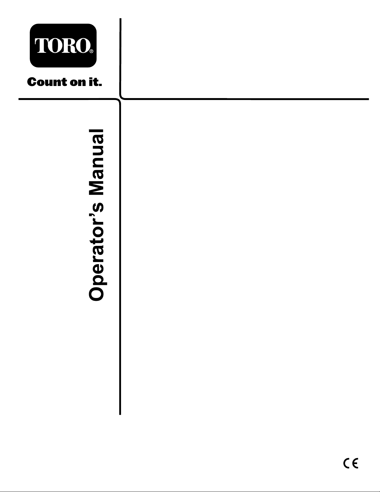
SafetyandInstructionalDecals
Safetydecalsandinstructionsareeasilyvisibletotheoperatorandarelocatednearanyareaof
potentialdanger.Replaceanydecalthatisdamagedorlost.
93-6674
1.Crushinghazard,hand—readtheinstructionsbefore
servicingorperformingmaintenance.
93-7272
1.Cutting/dismembermenthazard;fan—stayawayfrom
movingparts.
1.Lowheightofcut
adjustment
100-5623
2.Highheightofcut
adjustment
93-7275
1.ReadtheOperator’sManual.
2.Donotusestartingaids.
93-7818
1.Warning—readtheOperator’sManualforinstructionson
torquingthebladebolt/nutto115to149N•m(85to1 10
ft-lb).
100-6578
1.Entanglementhazard,belt—donotoperatethemachine
withtheshieldsorguardsremoved;alwayskeepthe
shieldsandguardsinplace;stayawayfrommovingparts.
100-5622
1.Heightofcutadjustment
8
Page 9
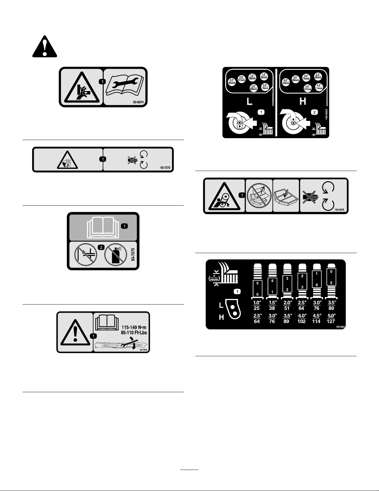
104-2277
2.
3.
1.
1.Tolocktheparkingbrake,
latchthepedalstogether,
applythebrakepedals,
andpullupontheknob.
2.Tounlocktheparking
brake,steponthebrake
pedals.
3.Parkingbrakelock
indicator
1.Lowheightofcut
adjustment
104-2277
4.ReadtheOperator’s
Manual.
5.Pressforoptional
headlights.
6.Pressdownontheleverto
tiltthesteeringwheel.
104-3579
2.Highheightofcut
adjustment
104-3599
1.Donotstephere.
2.Tractionpedal
3.Traction—forward
4.Traction—reverse
5.Danger—shutoffPTOpriortoraisingthecuttingunits;do
notoperatethecuttingunitswhentheyareintheraised
position.
104-8324
1.Raisecuttingunits2.Lowercuttingunits
9
Page 10
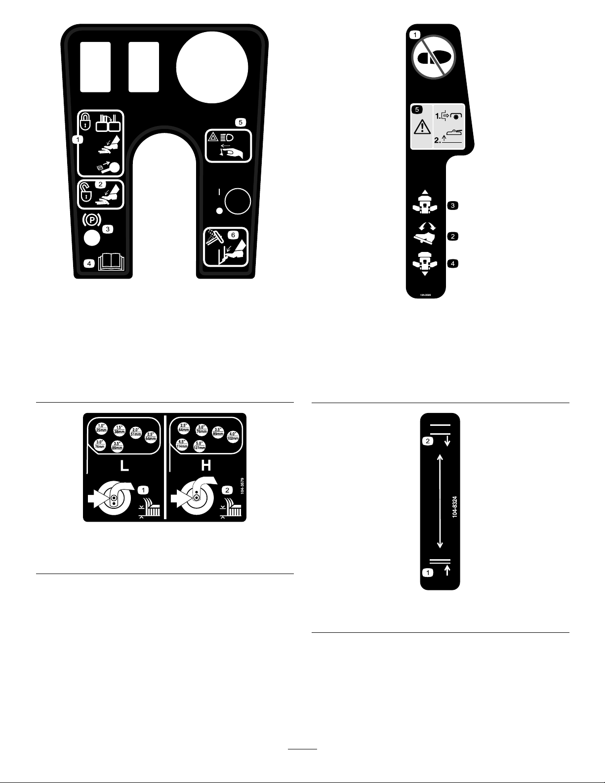
104-8325
1.Lock/unlockthecuttingunitservicelock.
106-4251
1.Heightofcut
1.Heightofcut
106-4250
1.Warning—wearhearingprotection.
98-4387
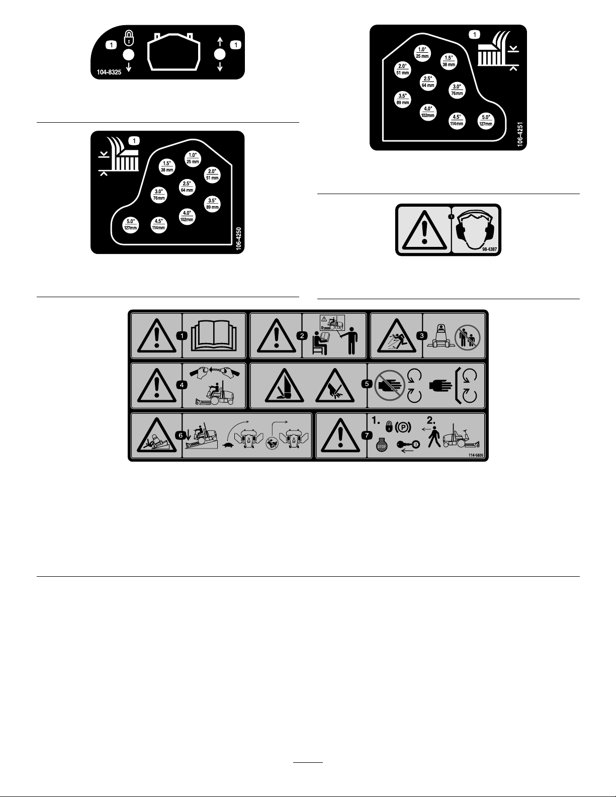
114-5605
1.Warning—readtheOperator’sManual.
2.Warning—donotoperatethismachineunlessyouaretrained.
3.Thrownobjecthazard—keepbystandersasafedistancefromthemachine.
4.Warning—weartheseatbeltwhenseatedintheoperator’sposition.
5.Cuttinghazardofhandorfoot—stayawayfrommovingparts;keepallguardsinplace.
6.Tippinghazard—lowerthecuttingunitwhendrivingdownslopes;slowmachinebeforeturning,donotturnathighspeeds
7.Warning—locktheparkingbrake,stoptheengineandremovetheignitionkeybeforeleavingthemachine.
10
Page 11
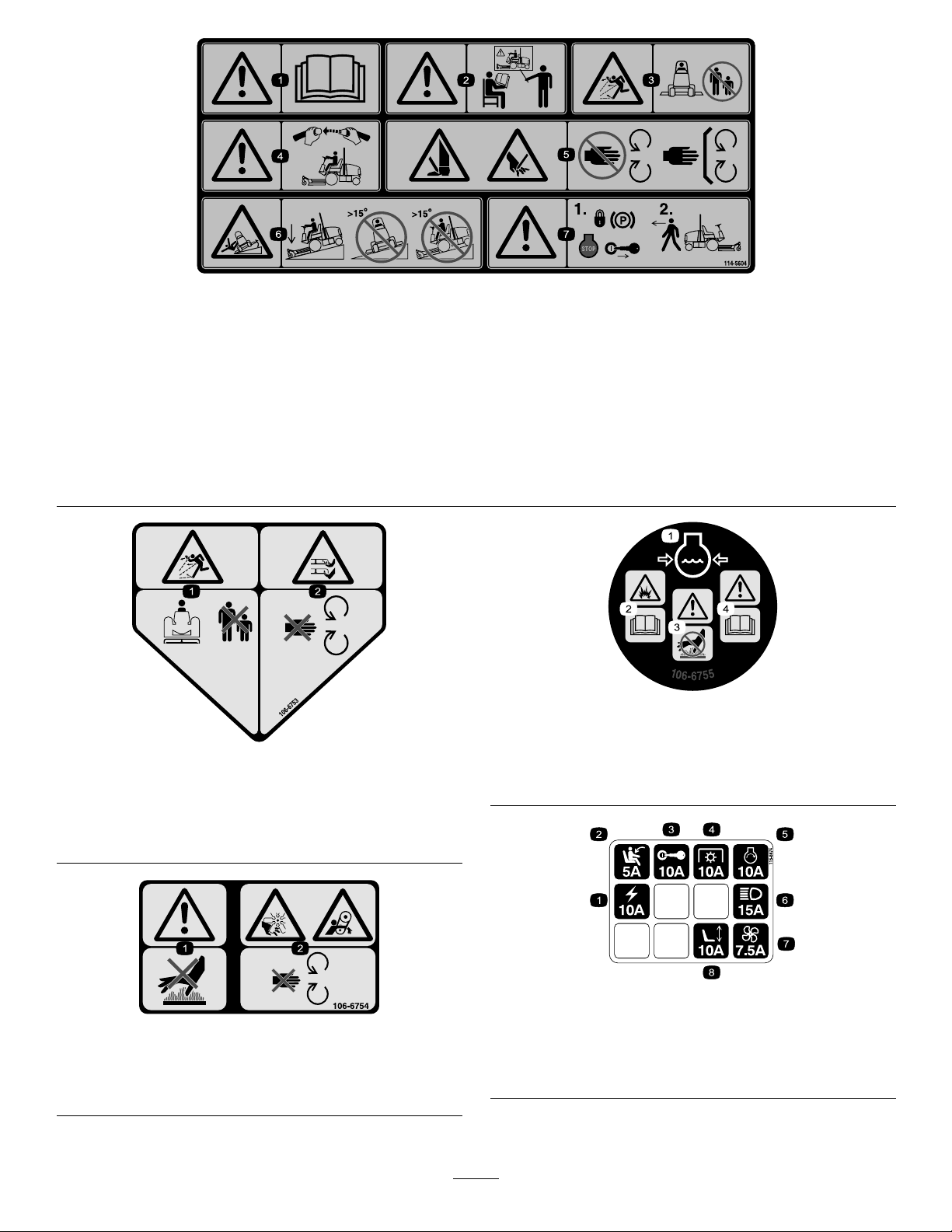
114-5604
(Afxoverpartno.114–5605forCE*)
*ThissafetydecalincludesaslopewarningrequiredonthemachineforcompliancetotheEuropeanLawnMowerSafetyStandardEN836:1997.Theconservativemaximum
slopeanglesindicatedforoperationofthismachineareprescribedbyandrequiredbythisstandard.
1.Warning—readtheOperator’sManual.
2.Warning—donotoperatethismachineunlessyouaretrained.
3.Thrownobjecthazard—keepbystandersasafedistancefromthemachine.
4.Warning—weartheseatbeltwhenseatedintheoperator’sposition.
5.Cuttinghazardofhandorfoot—stayawayfrommovingparts;keepallguardsinplace.
6.Tippinghazard—lowerthecuttingunitwhendrivingdownslopes;donotoperateonslopesgreaterthan15degrees.
7.Warning—locktheparkingbrake,stoptheengineandremovetheignitionkeybeforeleavingthemachine.
106-6755
106-6753
1.Enginecoolantunderpressure
2.Explosionhazard—readtheOperator’sManual.
3.Warning—donottouchthehotsurface.
4.Warning—readtheOperator’sManual.
1.Enginecoolantunder
pressure.
2.Explosionhazard—read
theOperator’sManual.
3.Warning—donottouch
thehotsurface.
4.Warning—readthe
Operator’sManual.
106-6754
1.Warning—donottouchthehotsurface.
2.Cutting/dismembermenthazard,fanandentanglement
hazard,belt—stayawayfrommovingparts.
1.Poweroutlet
2.Seatswitch
3.Ignitionswitch7.Fan
4.PowerTakeOff(PTO)
11
115-8474
5.Startersolenoid
6.LightKit
8.Powerseat
Page 12
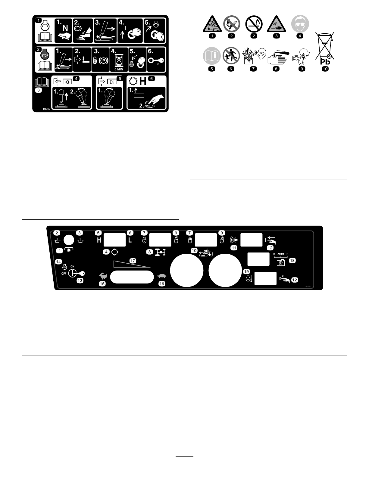
106-6764
1.Tostarttheengine,movethetractionpedaltoNeutral,
pressthebrakepedal,movethethrottlelevertomididle,
turntheignitionkeytoOn,andthenturntheignitionkeyto
Start;readtheOperatorsManual.
2.Tostoptheengine,movethethrottlelevertoslow,
disengagethePTO,settheparkingbrake,wait5minutes,
turntheignitionkeytoStop,andremovethekey;readthe
OperatorsManual.
3.ReadtheOperatorsManual.
4.ToengagethePTO,pulluponthePTOswitchandmove
itforward.
5.TodisengagethePTO,movethePTOswitchback.
6.Toswitchthetransmissiontohighspeed,raisethe
attachmentliftandswitchthespeedcontroltoHigh.
BatterySymbols
Someorallofthesesymbolsareonyourbattery
1.Explosionhazard
2.Nore,opename,or
smoking.
3.Causticliquid/chemical
burnhazard
4.Weareyeprotection9.Flusheyesimmediately
5.ReadtheOperator’s
Manual.
6.Keepbystandersasafe
7.Weareyeprotection;
8.Batteryacidcancause
10.Containslead;donot
distancefromthebattery.
explosivegasescan
causeblindnessandother
injuries
blindnessorsevereburns.
withwaterandgetmedical
helpfast.
discard.
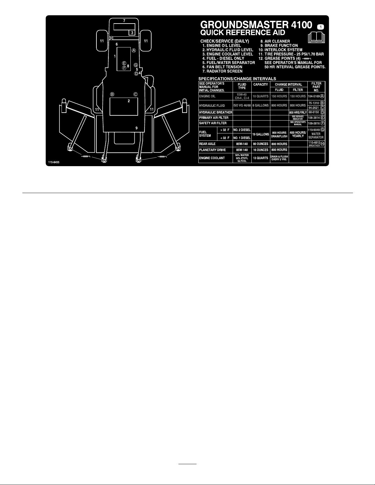
115-3753
1.PowerTake-off(PTO)
2.Engage7.Lock12.Pressthebutton
3.Disengage8.Flowdivider13.Keyswitch
4.Transmission9.Unlock14.Engine—preheat19.Enginecoolanttemperature
5.High
6.Low
10.Cruisecontrol(optional)
11.Silencerswitch16.Slow
17.Throttle-Continuous
variablesetting
18.Enginecoolingfanswitch
resetswitch
15.Fast
12
Page 13
1.ReadtheOperator’sManual.
115-8455
13
Page 14

Setup
LooseParts
Usethechartbelowtoverifythatallpartshavebeenshipped.
ProcedureDescription
1
2
3
Note:Determinetheleftandrightsidesofthemachine
fromthenormaloperatingposition.
Nopartsrequired
WarningDecal1
Operator’sManual
EngineOperator’sManual
PartsCatalog
OperatorTrainingMaterials
Pre-deliveryInspectionSheet
Declarationofconformity
1
GreasingtheMachine
Qty.
–
1
1
1
1
1
1
Greasethemachine.
Usedonlyonmachinesrequiring
EuropeanCEcompliance.
Readthemanualsandtrainingmaterials
beforeoperatingthemachine.Usethe
remainingpartsfortheinstallationof
attachments.
3
ReadingtheManualsand
ReviewtheTrainingMaterials
Partsneededforthisprocedure:
Use
NoPartsRequired
Procedure
Beforethemachineisoperated,itmustbegreased
toensureproperlubricatingcharacteristics;referto
GreasingtheBearingsandBushingsprocedureof
Lubrication,page33.Failuretoproperlygreasethe
machinewillresultinprematurefailureofcriticalparts.
2
ReplacingtheWarningDecal
Partsneededforthisprocedure:
1WarningDecal
Procedure
1
Operator’sManual
1
EngineOperator’sManual
1
PartsCatalog
1
OperatorTrainingMaterials
1
Pre-deliveryInspectionSheet
1
Declarationofconformity
Procedure
1.Readthemanuals.
2.ViewtheOperatorTrainingmaterials
OnmachinesrequiringEuropeanCEcompliance,
replacethewarningdecal,partno.114–5605withthe
warningdecalpartno.114–5604.
14
Page 15
ProductOverview
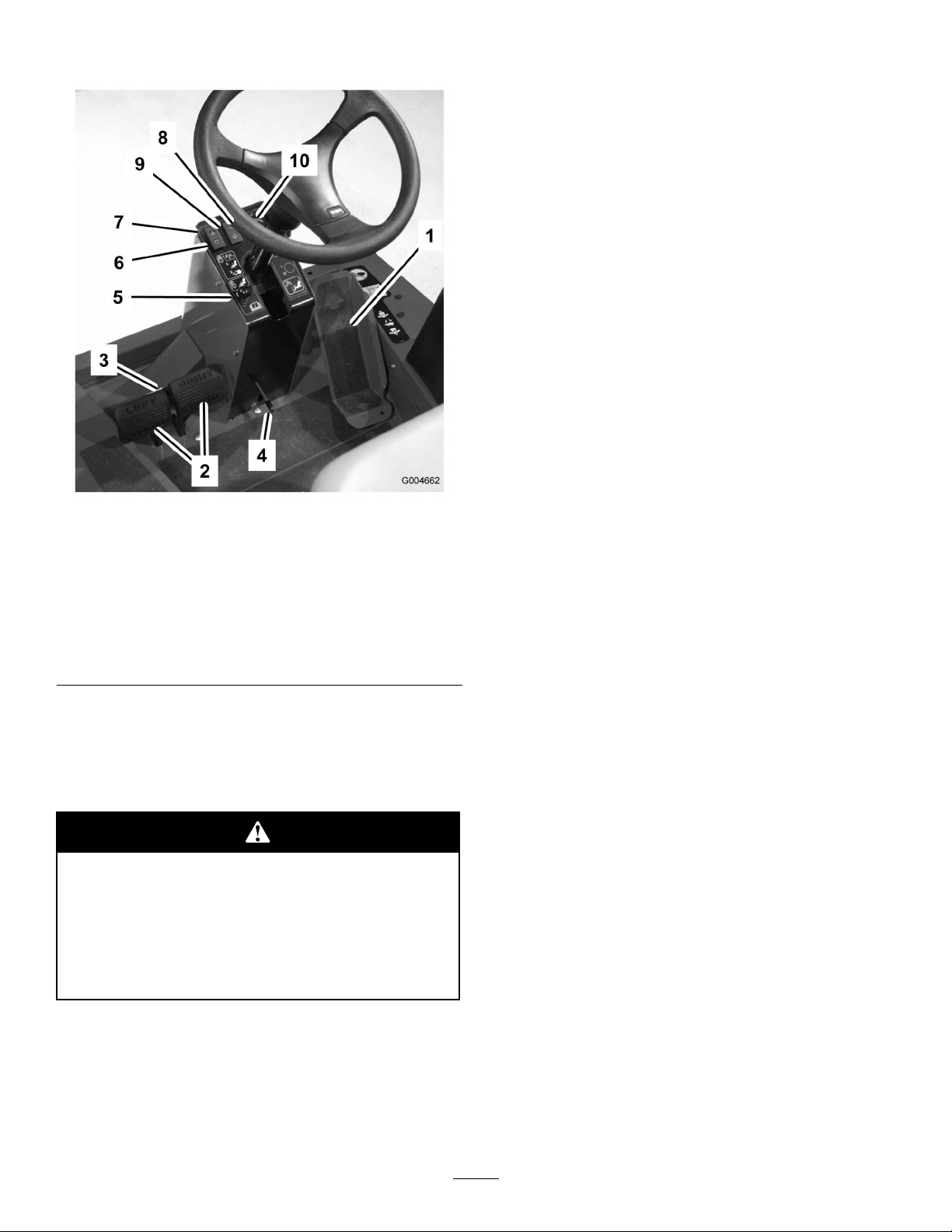
Figure2
1.Tractionpedal
2.Brakepedals7.Engineoilpressure
3.Pedallockinglatch8.Enginecoolant
4.Tiltsteeringlever
5.Parkingbrakelatch10.Temperaturegauge
6.Chargeindicator
warninglight
temperaturewarning
light
9.Glowplugindicatorlight
load,maximumgroundspeed,fullypressthepedalwhile
thethrottleisinFast.
Tostop,reduceyourfootpressureonthetractionpedal
andallowittoreturntothecenterposition.
BrakePedals
Twofootpedals(Figure2)operateindividualwheel
brakesforturningassistance,parking,andtoaidin
obtainingbettersidehilltraction.Alatchconnectsthe
pedalsforparkingbrakeoperationandtransport.
PedalLockingLatch
Thepedallockinglatch(Figure2)connectsthepedals
togethertoengagetheparkingbrake.
TiltSteeringLever
Pressthelever(Figure2)downtotiltthesteeringwheel
tothedesiredposition.Thenreleasethelevertolock
theadjustment.
ParkingBrakeLatch
Aknobontheleftsideoftheconsoleactuatesthe
parkingbrakelock(Figure2).Toengagetheparking
brake,connectthepedalswiththelockinglatch,push
downonbothpedals,andpulltheparkingbrakelatch
out.Toreleasetheparkingbrake,pressbothpedalsuntil
theparkingbrakelatchretracts.
Controls
Note:Determinetheleftandrightsidesofthemachine
fromthenormaloperatingposition.
Thismachineproducessoundlevelsinexcess
of85dBAattheoperatorsearandcancause
hearinglossthroughextendedperiodsof
exposure.
Wearhearingprotectionwhenoperatingthis
machine.
TractionPedal
Thetractionpedal(Figure2)controlsforwardand
reverseoperation.Pressthetopofthepedaltomove
forwardandthebottomtomovebackward.Ground
speeddependsonhowfaryoupressthepedal.Forno
ChargeIndicator
Thechargeindicator(Figure2)illuminateswhenthe
systemchargingcircuitmalfunctions.
EngineOilPressureWarningLight
Thelight(Figure2)illuminateswhentheengineoil
pressureisdangerouslylow .
EngineCoolantTemperatureWarning
Light
Thelight(Figure2)illuminatesandtheengineshuts
downwhencoolantreachesanexcessivelyhigh
temperature.
GlowPlugIndicatorLight
Whenlit,theglowplugindicatorlight(Figure2)
indicatesthattheglowplugsareon.
15
Page 16
EngineTemperatureGauge
KeySwitch
Thisgauge(Figure2)indicatestheenginecoolant
temperature.
SpeedLimiter
Adjustthescrew(Figure3)tolimittheamountthe
tractionpedalcanbedepressedintheforwarddirection
tolimitspeed.
Important:Thetractionpedalmustcontactthe
speedlimiterbeforereachingtheendofthepump
stroketopreventpumpdamage.
Thekeyswitch(Figure4)hasthreepositions:Off,
On/Preheat,andStart.
PTOSwitch
ThePTOswitch(Figure4)hasthreepositions:On
(engage),Neutral,andOff(disengage).Carefullylift
andpushthePTOswitchforwardtotheOnposition
tostarttheimplementorcuttingunitblades.Slowly
pulltheswitchbackwardtotheOffpositiontostop
implementoperation.
Important:Thecenterliftlevermustmomentarily
bepushedtothelowerpositiontoenablePTO
circuitactuationbyPTOswitch.
Hi-LoSpeedControl(Optional)
Thecontrol(Figure4)allowsthespeedrangetoincrease
fortransportofthemachine.
Figure3
1.Speedlimiter
Important:Wheninthemowposition,thespeed
limiterscrewmuststopthetractionpedalbeforethe
pumpreachesfullstrokeordamagetothepump
mayoccur.
LiftLevers
Theliftlevers(Figure4)raiseandlowerthecuttingunits.
Important:Thecenterliftlevermustmomentarily
bepushedtothelowerpositiontoenablePTO
circuitactuationbyPTOswitch.
CuttingUnitServiceLock
Thecuttingunitservicelock(Figure4)locksthefront
cuttingunitliftleverwhenthecuttingunitisinthe
raisedposition.
Figure4
1.Liftlever
2.Keyswitch10.T emperatureresetswitch
3.PTOswitch
4.Hi-lospeedcontrol
(optional)
5.Flowdividerswitch13.Throttle
6.Cruisecontrol(optional)
7.Alarmsilenceswitch15.Frontcuttingunitservice
8.Fanswitch
9.Audiblealarm
11.Hourmeter
12.Fuelgauge
14.Powerpoint
lock
CruiseControl(Optional)
Thecruisecontrol(Figure4)setsthespeedofthe
machine.
FuelGauge
Thefuelgauge(Figure4)indicatestheleveloffuelin
thetank.
16
Page 17

HourMeter
ThrottleControl
Thehourmeter(Figure4)showsthetotalhoursthatthe
machinehasbeenoperated.
TemperatureOverrideSwitch
Pressandholdtheresetswitch(Figure4)tostartthe
engineafterhightemperatureshutdown.Useonlyfor
Movethecontrol(Figure4)forwardtoincreasethe
enginespeedandrearwardtodecreasethespeed.
PowerPoint
Thepowerpoint(Figure4)isusedtopoweroptional
electricalaccessories.
emergencyoperation.
EngineCoolingFanSwitch
AudibleAlarm
Themachineisequippedwithahydraulicallydrivenauto
Thealarm(Figure4)isactivatedwhenthelowengine
oilpressurelightilluminatesorthehighcoolant
temperaturelightilluminates.
reversingenginecoolingfan.Thefanswitch(Figure4)
hasthreepositionsR(manualreverse),Auto(normal)
andF(forwardonly).RefertoEngineCoolingFan
OperationintheOperationSectionofmanual
AlarmSilenceSwitch
Thisswitch(Figure4)shutsofftheaudiblealarm.
Specications
Note:Specicationsanddesignaresubjecttochangewithoutnotice.
Widthofcut
overall
frontcuttingunit54inch(137cm)
sidecuttingunit
frontandonesidecuttingunit89inch(226cm)
Overallwidth
cuttingunitsdown
cuttingunitsup(transports)71inch(180cm)
Overalllength144inch(366cm)
Height
HeightwithROPS81inch(206cm)
Groundclearance6inch(15cm)
Wheeltread(tocenteroftire)
front45inch(1 14cm)
rear
Wheelbase
124inch(315cm)
37inch(94cm)
127inch(322cm)
58inch(147cm)
47inch(119cm)
55-1/2inch(141cm)
Attachments/Accessories
AselectionofToroapprovedattachmentsand
accessoriesareavailableforusewiththemachineto
enhanceandexpanditscapabilities.Contactyour
AuthorizedServiceDealerorDistributororgoto
www.Toro.comforalistofallapprovedattachments
andaccessories.
Weight(withcuttingunitsanduids)4211lb(1910kg)
17
Page 18
Operation
Note:Determinetheleftandrightsidesofthe
machinefromthenormaloperatingposition.
BeforeOperating
Ifyouleavethekeyintheignitionswitch,
someonecouldaccidentlystarttheengineand
seriouslyinjureyouorotherbystanders.
Removethekeyfromtheignitionbeforeyoudo
anymaintenance.
CheckingtheEngineOil
ServiceInterval:Beforeeachuseordaily
Theengineisshippedwithoilinthecrankcase;
however,theoillevelmustbecheckedbeforeandafter
theengineisrststarted.
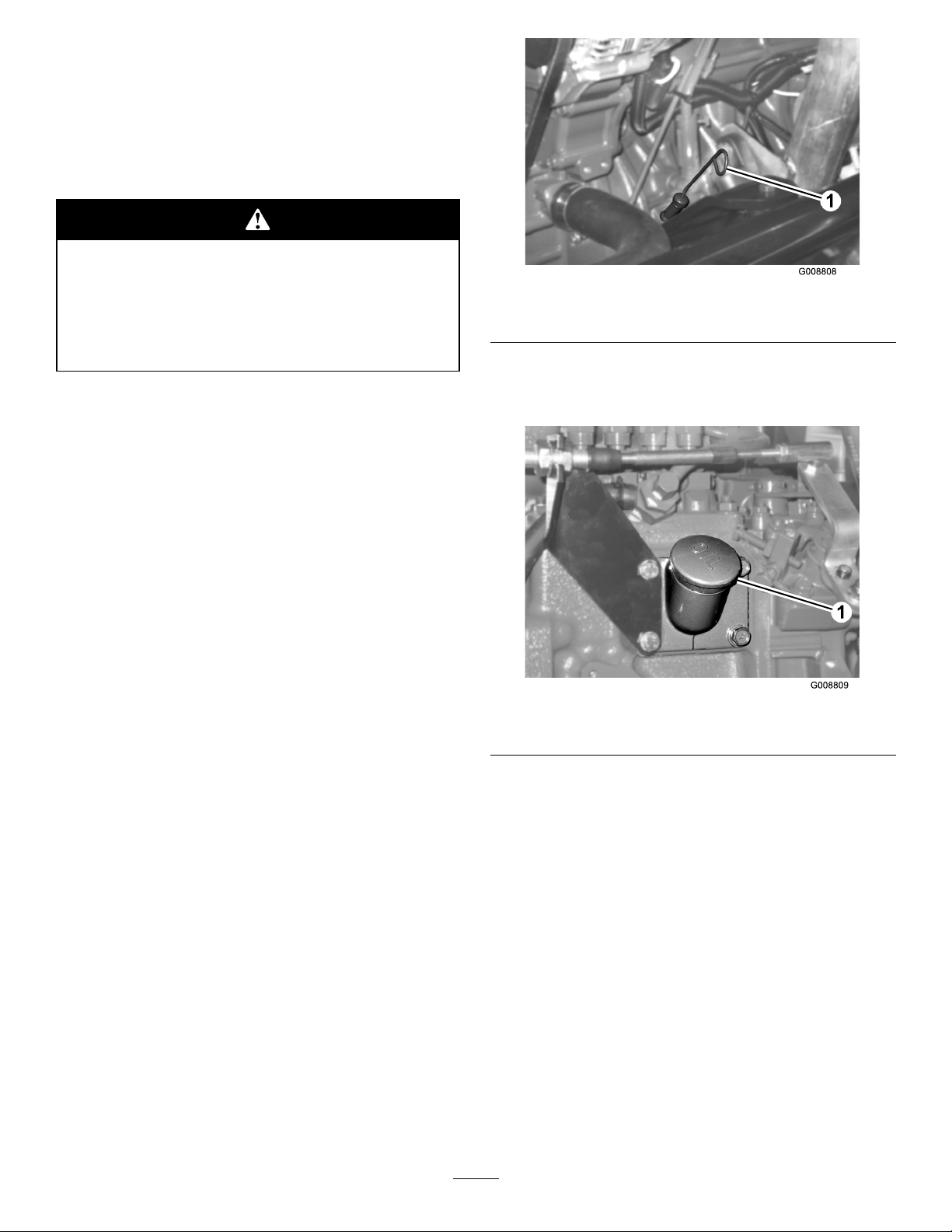
Figure5
1.Dipstick
4.IftheoilisbelowtheFullmark,removethellcap
(Figure6)andaddoiluntilthelevelreachestheFull
mark.Donotoverll.
Thecrankcasecapacityis10qt(9.5l)withthelter.
Usehigh-qualityengineoilthatmeetsthefollowing
specications:
•APIClassicationLevelRequired:CH-4,CI-4or
higher.
•Preferredoil:SAE15W -40(above0°F)
•Alternateoil:SAE10W-30or5W -30(all
temperatures)
ToroPremiumEngineOilisavailablefromyour
distributorineither15W-40or10W-30viscosity .See
thepartscatalogforpartnumbers.
Note:Thebesttimetochecktheengineoiliswhenthe
engineiscoolbeforeithasbeenstartedfortheday .Ifit
hasalreadybeenrun,allowtheoiltodrainbackdown
tothesumpforatleast10minutesbeforechecking.
Iftheoillevelisatorbelowthe“add”markonthe
dipstick,addoiltobringtheoilleveltothe“full”mark.
DONOTOVERFILL.Iftheoillevelisbetweenthe
“full”and“add”marks,nooiladditionisrequired.
1.Parkthemachineonalevelsurface.Unlockthe
enginecoverlatches.
2.Opentheenginecover.
Figure6
1.Oilllcap
Note:Whenusingdifferentoil,drainalloldoil
fromthecrankcasebeforeaddingnewoil.
5.Installtheoilllcapanddipstick.
6.Closetheenginecoverandsecureitwiththelatches.
CheckingtheCoolingSystem
ServiceInterval:Beforeeachuseordaily
Checklevelofcoolantatthebeginningofeachday.
Capacityofsystemis13qts.(12.3l).
1.Carefullyremovetheradiatorcapandexpansion
tankcap(Figure7).
3.Removethedipstick,wipeitclean,installthe
dipstickintothetube,andpullitoutagain.Theoil
levelshouldbeuptotheFULLmark(Figure5).
18
Page 19
Iftheenginehasbeenrunning,thepressurized,
hotcoolantcanescapeandcauseburns.
•Donotopentheradiatorcapwhenthe
engineisrunning.
•Usearagwhenopeningtheradiatorcap,
andopenthecapslowlytoallowsteamto
escape.
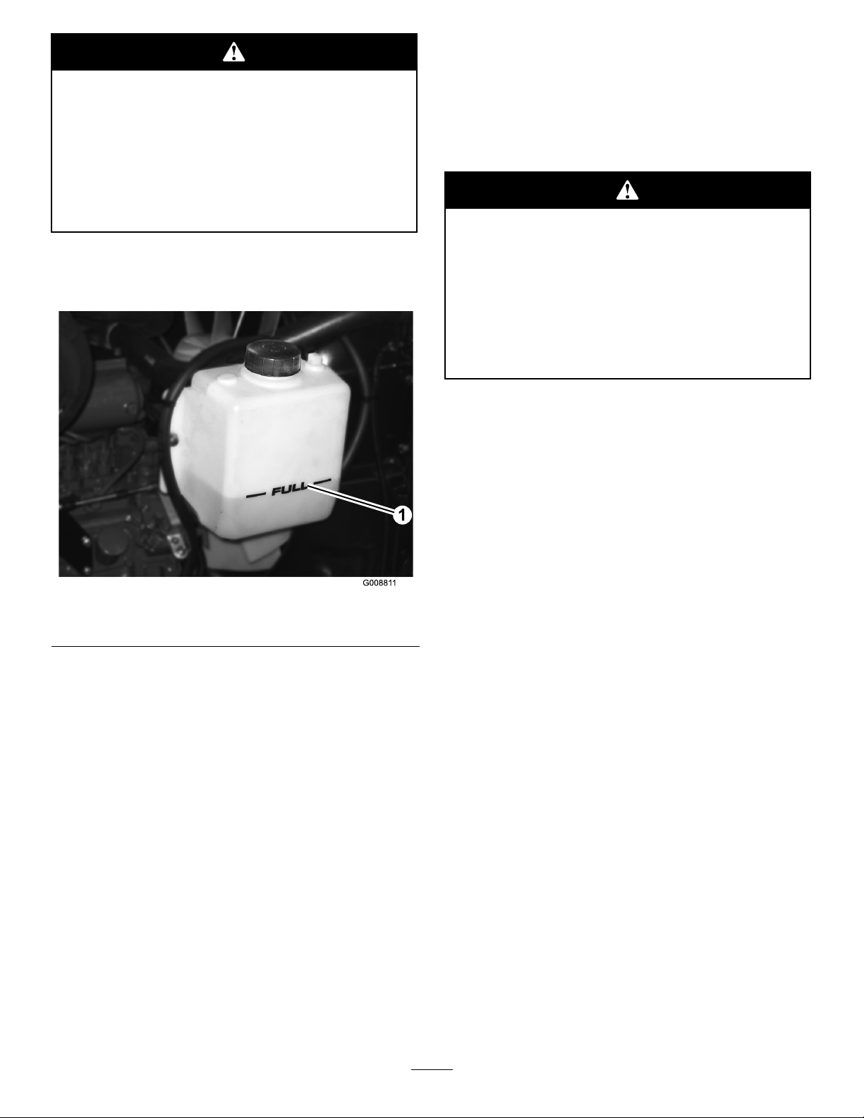
2.Checkthecoolantlevelintheradiator.Theradiator
shouldbelledtothetopofthellerneckandthe
expansiontanklledtotheFullmark.
Useofsummergradefuelabove20°F(-7°C)will
contributetowardlongerfuelpumplifeandincreased
powercomparedtowintergradefuel.
Important:Donotusekeroseneorgasoline
insteadofdieselfuel.Failuretoobservethis
cautionwilldamagetheengine.
Fuelisharmfulorfatalifswallowed.Long-term
exposuretovaporscancauseseriousinjuryand
illness.
•Avoidprolongedbreathingofvapors.
•Keepfaceawayfromnozzleandgastankor
conditioneropening .
•Keepfuelawayfromeyesandskin.
BiodieselReady
Thismachinecanalsouseabiodieselblendedfuel
ofuptoB20(20%biodiesel,80%petrodiesel).The
petrodieselportionshouldbeloworultralowsulfur.
Observethefollowingprecautions:
Figure7
1.Expansiontank
3.Ifthecoolantislow ,adda50/50mixtureofwater
andethyleneglycolanti-freeze.Donotusewater
onlyoralcohol/methanolbasecoolants.
4.Installtheradiatorcapandexpansiontankcap.
AddingFuel
Useonlyclean,freshdieselfuelorbiodieselfuelswith
low(<500ppm)orultralow(<15ppm)sulfurcontent.
Theminimumcetaneratingshouldbe40.Purchase
fuelinquantitiesthatcanbeusedwithin180daysto
ensurefuelfreshness.
Fueltankcapacity:19USgallons(72l)
•Thebiodieselportionofthefuelmustmeet
specicationASTMD6751orEN14214.
•TheblendedfuelcompositionshouldmeetASTM
D975orEN590.
•Paintedsurfacesmaybedamagedbybiodiesel
blends.
•UseB5(biodieselcontentof5%)orlesserblends
incoldweather.
•Monitorseals,hoses,gasketsincontactwithfuelas
theymaybedegradedovertime.
•Fuellterpluggingmaybeexpectedforatimeafter
convertingtobiodieselblendsd.
•Contactyourdistributorifyouwishformore
informationonbiodiesel.
Usesummergradedieselfuel(No.2-D)attemperatures
above20°F(-7°C)andwintergrade(No.1-Dor
No.1-D/2-Dblend)belowthattemperature.Useof
wintergradefuelatlowertemperaturesprovideslower
ashpointandcoldowcharacteristicswhichwillease
startingandreducefuellterplugging.
19
Page 20
Incertainconditions,fuelisextremely
ammableandhighlyexplosive.Areor
explosionfromfuelcanburnyouandothers
andcandamageproperty.
•Fillthefueltankoutdoors,inanopenarea,
whentheengineiscold.Wipeupanyfuel
thatspills.
•Neverllthefueltankinsideanenclosed
trailer.
2.Usingacleanrag,cleanareaaroundfueltankcap.
3.Removecapfromthefueltank(Figure8).
•Neversmokewhenhandlingfuel,andstay
awayfromanopenameorwherefuel
fumesmaybeignitedbyaspark.
•Storefuelinanapprovedcontainerandkeep
itoutofthereachofchildren.Neverbuy
morethana30-daysupplyoffuel.
•Donotoperatewithoutentireexhaust
systeminplaceandinproperworking
condition.
Incertainconditionsduringfueling,static
electricitycanbereleasedcausingaspark
whichcanignitethefuelvapors.Areor
explosionfromfuelcanburnyouandothers
andcandamageproperty.
•Alwaysplacefuelcontainersontheground
awayfromyourvehiclebeforelling.
•Donotllfuelcontainersinsideavehicle
oronatruckortrailerbedbecauseinterior
carpetsorplastictruckbedlinersmay
insulatethecontainerandslowthelossof
anystaticcharge.
•Whenpractical,removeequipmentfromthe
truckortrailerandrefueltheequipment
withitswheelsontheground.
•Ifthisisnotpossible,thenrefuelsuch
equipmentonatruckortrailerfroma
portablecontainer,ratherthanfromafuel
dispensernozzle.
•Ifafueldispensernozzlemustbeused,keep
thenozzleincontactwiththerimofthefuel
tankorcontaineropeningatalltimesuntil
fuelingiscomplete.
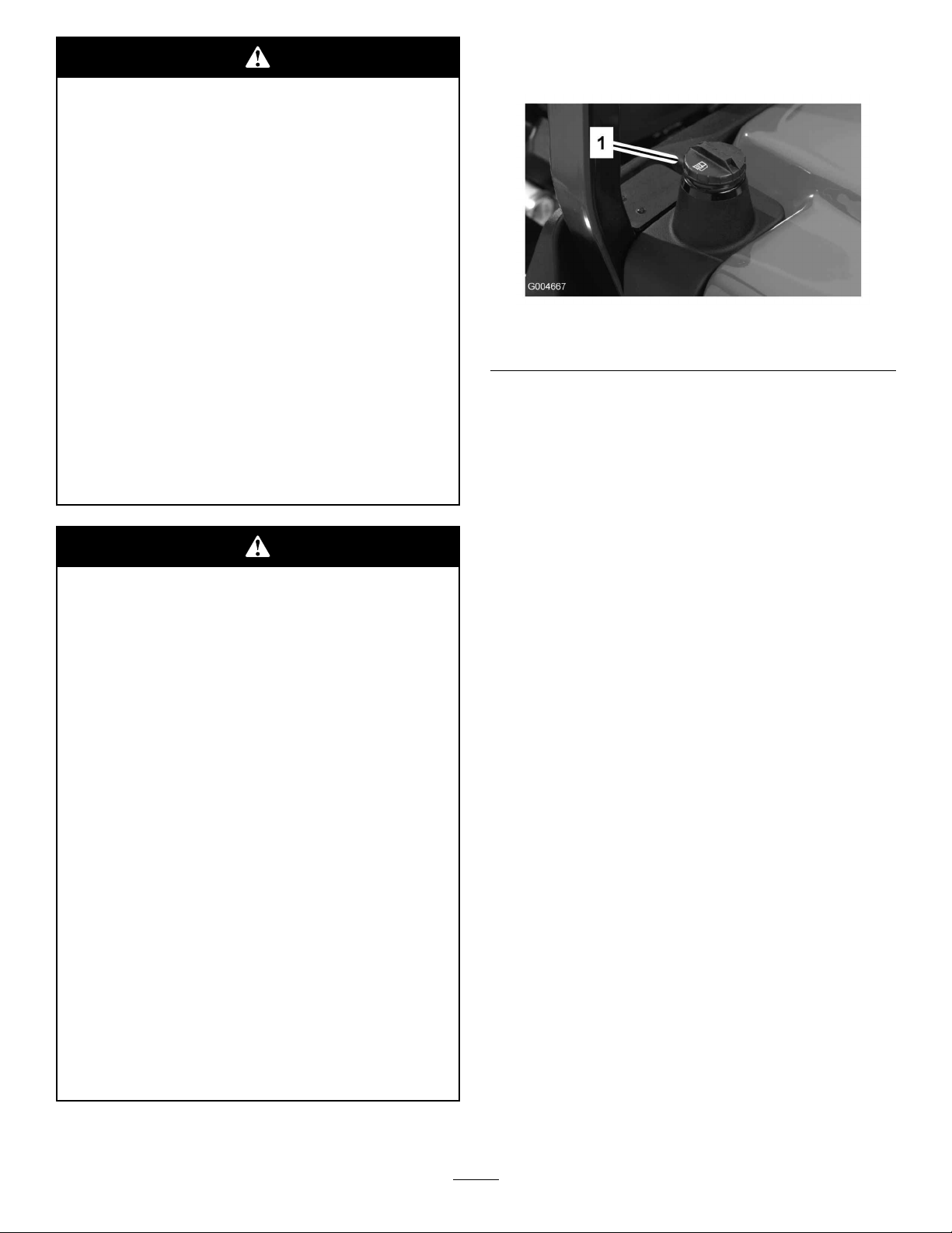
1.Parkthemachineonalevelsurface.
Figure8
1.Fueltankcap
4.Fillthetankuntilthelevelistothebottomofthe
llerneckwithdieselfuel.
5.Installfueltankcaptightlyafterllingtank.
Note:Ifpossible,llthefueltankaftereachuse.
Thiswillminimizepossiblebuildupofcondensation
insidethefueltank.
CheckingtheHydraulicFluid
ServiceInterval:Beforeeachuseordaily
Themachinesreservoirislledatthefactorywith
approximately8U.S.gallons(30.2l)ofhighquality
hydraulicuid.Checkthelevelofthehydraulic
uidbeforetheengineisrststartedanddaily
thereafter.Therecommendedreplacementuidis:
ToroPremiumAllSeasonHydraulicFluid
(Availablein5gallonpailsor55gallondrums.Seeparts
catalogorTorodistributorforpartnumbers.)
Alternateuids:IftheTorouidisnotavailable,other
uidsmaybeusedprovidedtheymeetallthefollowing
materialpropertiesandindustryspecications.W edo
notrecommendtheuseofsyntheticuid.Consult
withyourlubricantdistributortoidentifyasatisfactory
product.
Note:Torowillnotassumeresponsibilityfordamage
causedbyimpropersubstitutions,souseonlyproducts
fromreputablemanufacturerswhowillstandbehind
theirrecommendation.
HighViscosityIndex/LowPourPointAnti-wear
HydraulicFluid,ISOVG46
MaterialProperties:
St@40°C44to48 Viscosity,ASTMD445
St@100°C7.9to8.5
20
Page 21

HighViscosityIndex/LowPourPointAnti-wear
HydraulicFluid,ISOVG46(cont'd.)
ViscosityIndexASTMD2270
PourPoint,ASTMD97-34°Fto-49°F
IndustrySpecications:VickersI-286-S(Quality
Level),VickersM-2950-S
(QualityLevel),Denison
140to160
Note:Manyhydraulicuidsarealmostcolorless,
makingitdifculttospotleaks.Areddyeadditivefor
thehydraulicsystemoilisavailablein2/3oz(20ml)
bottles.Onebottleissufcientfor4-6gallons(15-22
1)ofhydraulicoil.Orderpartno.44-2500fromyour
authorizedTorodistributor.
1.Positionthemachineonalevelsurface,lowerthe
cuttingunits,stoptheengine,andremovethekey.
2.Unlatchtheseat,raiseit,andengagetheproprod.
3.Cleantheareaaroundthellerneckandcapofthe
hydraulictank(Figure9).Removethecapfromthe
llerneck.
CheckingthePlanetaryGearDriveOil
ServiceInterval:Every400hours
Checktheoillevelafterevery400hoursofoperation
orifexternalleakageisnoted.UsehighqualitySAE
85W-140gearlubeasareplacement.
Thecapacityofthesystemisapproximately16oz(0.5
HF-0
l).
1.Withthemachineonalevelsurface,positionthe
wheelsothatthecheck/drainplug(Figure10)isat
eitherthe2or10o’clockposition.
Figure9
1.Hydraulictankcap
4.Removethedipstickfromthellerneckandwipe
itwithacleanrag.Insertthedipstickintotheller
neck;thenremoveitandchecktheuidlevel.The
uidlevelshouldbebetweenthetwomarksonthe
dipstick.
5.Ifthelevelislow,addtheappropriateuidtoraise
theleveltotheuppermark.
6.Installthedipstickandcapontothellerneck.
Figure10
1.Check/drainplug
2.Removetheplugontheplanetary(Figure10)
andchecktheplugonthebacksideofthebrake
(Figure11).Oilshouldbeatthebottomofthe
checkplugholeonthebacksideofthebrake.
Figure11
1.Brakehousing
2.Checkplug
21
Page 22

3.Addgearoiltotheholeintheplanetary,ifnecessary,
tobringtheoiluptotheproperlevel.Installthe
plug.
4.Repeatsteps1-3ontheoppositegearassembly.
CheckingtheRearAxleLubricant
ServiceInterval:Every400hours
TherearaxleislledwithSAE85W -140gearlube.
Checktheoillevelbeforetheengineisrststartedand
every400hoursthereafter.Thecapacityis80oz(2.4l).
Visuallyinspectforleaksdaily.
1.Positionthemachineonalevelsurface.
2.Removeacheckplugfromoneendoftheaxle
(Figure12)andmakesurethatthelubricantisupto
thebottomofthehole.Ifthelevelislow,remove
thellplug(Figure12)andaddenoughlubricantto
bringtheleveluptothebottomofthecheckplug
holes.
Figure13
1.Gearbox2.Check/llplug
CheckingtheTirePressure
ServiceInterval:Beforeeachuseordaily
Thetiresareover-inatedforshipping.Therefore,
releasesomeoftheairtoreducethepressure.The
correctairpressureinthefrontandreartiresis25-30
psi(172-207kPa).
Figure12
1.Checkplug
2.Fillplug
CheckingtheRearAxleGearBox
Lubricant
ServiceInterval:Every400hours
ThegearboxislledwithSAE85W-140gearlube.
Checktheoillevelbeforetheengineisrststartedand
every400hoursthereafter.Thecapacityis16oz(0.5l).
Visuallyinspectforleaksdaily.
1.Positionthemachineonalevelsurface.
2.Removethecheck/llplugfromtheleftsideofthe
gearbox(Figure13)andmakesurethatlubricant
isuptothebottomofthehole.Ifthelevelislow,
addenoughlubricanttobringtheleveluptothe
bottomofthehole.
Important:Maintainevenpressureinalltiresto
ensureagoodquality-of-cutandpropermachine
performance.
Do not under -inate.
CheckingtheTorqueoftheWheelNuts
orBolts
ServiceInterval:Aftertherst10hours
Every200hours
Failuretomaintainpropertorqueofthewheel
nutscouldresultinfailureorlossofwheeland
mayresultinpersonalinjury.
Torquethefrontwheelnutsandrearboltsto
85-100ft-lb(115-136N⋅ ⋅⋅m)after1-4hoursof
operationandagainafter10hoursofoperation.
Torqueevery200hoursthereafter.
AdjustingtheHeight-of-Cut
CenterCuttingUnit
Theheight-of-cutisadjustablefrom1to5inches(25
to127mm)in1/2inch(13mm)increments.Toadjust
theheight-of-cutonthefrontcuttingunit,positionthe
castorwheelaxlesintheupperorlowerholesofthe
22
Page 23

castorforks,addorremoveanequalnumberofspacers
fromthecastorforks,andsecuretherearchaintothe
desiredhole.
1.Starttheengineandraisethecuttingunitssothat
theheight-of-cutcanbechanged.Stoptheengine
andremovethekeyafterthecuttingunitisraised.
2.Positionthecastorwheelaxlesinthesameholes
inallcastorforks.Refertothefollowingchartto
determinethecorrectholesforthesetting.
below)ontothespindleshafttogetthedesired
height-of-cut;thenslidethewasherontotheshaft.
Refertothefollowingcharttodeterminethe
combinationsofspacersforthesetting:
Figure15
4.Pushthecastorspindlethroughthefrontcastor
arm.Installtheshims(astheywereoriginally
installed)andtheremainingspacersontothe
spindleshaft.Installthetensioningcaptosecure
theassembly .
Figure14
1.Castorwheel4.Shims
2.Tensioningcap5.Axlemountingholes
3.Spacers
Note:Whenoperatingin2-1/2inch(64mm)
heightofcutorhigher,theaxleboltmustbe
installedinthelowercastorforkholetoprevent
grassbuildupbetweenthewheelandthefork.
Whenoperatinginheightofcutslowerthan2-1/2
inches(64mm)andgrassbuildupisdetected,
reversethemachinesdirectiontopullanyclippings
awayfromthewheel/forkarea.
5.Removethehairpincotterandclevispinsecuring
theheight-of-cutchainstotherearofthecutting
unit(Figure16).
Figure16
1.Height-of-cutchain
2.U-bolt
6.Mounttheheight-of-cutchainstothedesired
height-of-cuthole(Figure17)withtheclevispin
andhairpincotter.
3.Removethetensioningcapfromthespindleshaft
(Figure14)andslidethespindleoutofthecastor
arm.Putthe2shims(1/8inch[3mm])ontothe
spindleshaftastheywereoriginallyinstalled.These
shimsarerequiredtoachievealevelacrosstheentire
widthofthecuttingunits.Slidetheappropriate
numberof1/2inchspacers(refertothechart
23
Page 24

Figure17
Note:Whenusing1inch(25mm),1-1/2inch(38
mm),oroccasionally2inch(51mm)height-of-cut,
movetheskidsandgagewheelstothehighest
position.
WingCuttingUnits
Toadjusttheheight-of-cutonthesidecuttingunits,add
orremoveanequalnumberofspacersfromthecastor
forks,positionthecastorwheelaxlesinthehighorlow
height-of-cutholesinthecastorforks,andsecurethe
pivotarmstotheselectedheight-of-cutbracketholes.
1.Positionthecastorwheelaxlesinthesameholes
inallofthecastorforks(Figure18andFigure20).
Refertothefollowingcharttodeterminethe
correctholeforthesetting.
2.Removethetensioningcapfromthespindleshaft
(Figure18)andslidethespindleoutofcastorarm.
Putthetwoshims(1/8inch[3mm])ontospindle
shaftastheywereoriginallyinstalled.Theseshims
arerequiredtoachievealevelacrosstheentire
widthofthecuttingunits.Slidetheappropriate
numberof1/2inchspacersontothespindleshaft
togetthedesiredheight-of-cut;thenslidethe
washerontotheshaft.
Figure18
1.Castorwheel4.Shims
2.Tensioningcap5.Axlemountingholes
3.Spacers
Refertothefollowingcharttodeterminethe
combinationsofspacersforthesetting.
Figure19
3.Pushthecastorspindlethroughthecastorarm.
Installtheshims(asoriginallyinstalled)andthe
remainingspacersontothespindleshaft.Installthe
tensioningcaptosecuretheassembly .
4.Removethehairpincotterandclevispinsfromthe
castorpivotarms(Figure20).
5.Rotatetensionrodtoraiseorlowerpivotarm
untilholesarealignedwithselectedheight-of-cut
bracketholesinthecuttingunitframe(Figure20
andFigure21).
24
Page 25

6.Inserttheclevispinsandinstallthehairpincotters.
7.Rotatetensionrodcounterclockwise(ngertight)
toputtensiononadjustment.
Figure20
1.Castorpivotarm3.Clevispinandhairpin
cotter
2.Axlemountingholes4.T ensionrod
Figure22
1.Skid
AdjustingtheCuttingUnitRollers
Thecuttingunitrollersshouldbemountedinthelower
positionwhenoperatinginheightofcutsgreaterthan
2-1/2inches(64mm)andinthehigherpositionwhen
operatinginheightofcutslowerthan2-1/2inches(64
mm).
1.Removetheboltandnutsecuringthegagewheelto
thecuttingunitbrackets(Figure23).
Figure21
AdjustingtheSkids
Theskidsshouldbemountedinthelowerposition
whenoperatinginheightofcutsgreaterthan2-1/2
inches(64mm)andinthehigherpositionwhen
operatinginheightofcutslowerthan2-1/2inches(64
mm).
Adjusttheskidsbyremovingtheangeboltandnuts,
positioningthemasdesired,andinstallingthefasteners
(Figure22).
Figure23
1.Gagewheel
2.Aligntherollerandspacerwiththetopholesinthe
bracketsandsecurethemwiththeboltandnut.
AdjustingtheBlade
Toensureproperoperationofthecuttingunit,there
mustbe0.38-0.62inch(10-16mm)clearancebetween
thetipsofthewingandcentercuttingunitblades
(Figure24).
1.Raisecuttingunitsobladesarevisibleandblock
centerdecksectionsoitcannotfallaccidentally.
Wingdecksmustbehorizontaltocentercutting
unit.
2.Rotateacenterandadjoiningwingbladesothere
bladetipsarealigned.Measuredistancebetween
bladetips,distanceshouldbeapproximately
0.38-0.62inch(10-16mm)(Figure24).
25
Page 26

Figure24
3.Toadjustdistance,locateadjusterboltonrearpivot
linkofcuttingunit(Figure25).Loosenjamnuton
adjusterbolt.Loosenortightenadjusterboltsuntil
0.38-0.62inch(10-16mm)clearanceisattained,
thentightenjamnut.
4.Repeatprocedureonoppositesideofcuttingdeck.
6.Cutgrassinatestareatodetermineifallcutting
unitsarecuttingatthesameheight.
7.Ifcuttingunitadjustmentsarestillneeded,ndaat
surfaceusinga6foot(2m)orlongerstraightedge.
8.Toeasemeasuringbladeplane,raisetheheightof
cuttothehighestposition;refertoAdjustingthe
HeightofCut.
9.Lowercuttingunitsontotheatsurface.Remove
thecoversfromthetopofthecuttingunits.
10.Loosentheangenut,securingtheidlerpulley,to
releasethebelttensiononeachcuttingunit.
CenterCuttingUnitSetup
Rotatebladeoneachspindleuntiltheendsfaceforward
andbackward.Measurefromtheoortothefront
tipofthecuttingedge.Adjust1/8inchshimson
frontcastorfork(s)tomatchheightofcuttodecal
(Figure26);refertoAdjustingtheCuttingUnitPitch
procedureinMowerMaintenance,page50.
Figure25
1.Adjusterbolt2.Jamnut
CorrectingMismatchBetweenCutting
Units
Duetodifferencesingrassconditionsandthe
counterbalancesettingofthetractionunit,itisadvised
thatgrassbecutandappearancecheckedbeforeformal
cuttingisstarted.
1.Setallcuttingunitstothedesiredheightofcut;
refertoAdjustingtheHeightofCuttablein
Specications,page17.
2.Checkandadjustfrontandreartractortirepressure
to25-30psi(172-207kPa).
3.Checkandadjustallcastortirepressuresto50psi
(345kPa).
4.Checkchargeandcounterbalancepressures
withengineathighidleusingtestportsdened
inHydraulicSystemsTestPorts.Adjust
counterbalancesettingtobe230psi(1585kPa)
higherthanchargepressurereading.
5.Checkforbentblades;refertoCheckingforaBent
BladeprocedureinMowerMaintenance,page50.
Figure26
1.Castorwheel4.Shims
2.Tensioningcap5.Axlemountingholes
3.Spacers
WingCuttingUnitSetup
Rotatebladeofeachspindleuntiltheendsfaceforward
andbackward.Measurefromtheoortothefront
tipofthecuttingedge.Adjust1/8inchshimson
frontcastorarm(s)tomatchheightofcuttodecal
26
Page 27

(Figure27).Fortheoutsidebladespindleonly,referto
AdjustingtheCuttingUnitPitchprocedureinMower
Maintenance,page50.
Figure27
1.Frontcastorarm
MatchingHeightOfCutBetweenCuttingUnits
1.Positionbladesidetosideonoutsidespindleof
bothwingcuttingunits.Measurefromtheoor
tothetipofthecuttingedgeonbothunitsand
compare.Thesenumbersshouldbewithin1/8inch
(3mm)ofeachother.
2.Movethethrottlecontroltothemid-idleposition.
3.TurntheignitionkeytotheRunposition.Theglow
indicatorwilllight.
4.Whentheglowindicatordims,turntheignitionkey
totheStartposition.Releasethekeyimmediately
whentheenginestartsandallowittoreturntothe
Runposition.Allowenginetowarmupatmid
speed(withoutload),thenmovethethrottlecontrol
tothedesiredposition.
Important:Donotrunthestartermotor
morethan15secondsatatimeorpremature
starterfailuremayresult.Iftheenginefailsto
startafter15seconds,turnthekeytotheOff
position,recheckthecontrolsandprocedures,
wait15additionalseconds,andrepeatthe
startingprocedure.
Whenthetemperatureislessthan20°F(-75C),
preheatglowplugstwicepriortoinitialcranking
attempt.Thestartermotorcanberunfor30
secondsonthen60secondsofffor2attempts.
5.Tostoptheengine,movethethrottlecontrol
backwardtotheSlowposition,movethePTOlever
totheOffposition,settheparkingbrake,androtate
theignitionkeytoOff.Removethekeyfromthe
switchtopreventaccidentalstarting.
Important:Allowenginetoidlefor5minutes
beforeshuttingitoffafterafullloadoperation.
Failuretodosomayleadtoturbo-chargertrouble.
2.Addorremove1/8inchshimsasneededonwing
castorwheels.Recheckmeasurementbetween
outsideedgesofbothwingcuttingunitsandadjust
asnecessary.
StartingandStoppingthe
Engine
Important:Thefuelsystemwillautomatically
bleeditselfwhenanyofthefollowingsituations
occur:
•Initialstartupofanewmachine.
•Theenginehasceasedrunningduetolackoffuel.
•Maintenancehasbeenperformeduponthefuel
systemcomponents.
RefertotheBleedingAirfromtheInjectorsprocedure
inFuelSystemMaintenance,page39.
1.Ensurethattheparkingbrakeisset.Removeyour
footfromthetractionpedalandensurethatitisin
neutral.
EngineCoolingFanOperation
Theenginecoolingfanswitchhasthreepositionsfor
controllingtheoperationofthefan.Thethreepositions
areR,AutoandF .Thefanhastheabilitytoreverse
toblowdebrisoffoftherearscreen.Undernormal
operatingconditions,theswitchshouldbeintheAuto
position.InAuto,thefanspeedwillbecontrolledby
thecoolanttemperatureandwillautomaticallyreverse
toblowdebrisoffoftherearscreen.Areversecycle
isautomaticallyinitiatedwheneitherthecoolantor
hydraulictemperaturereachesacertainpoint.By
pressingthefanswitchforwardintotheRposition,the
fanwillcompleteamanuallyinitiatedreversecycle.This
positionisspringloadedmeaningthattheswitchwill
returntotheAutopositionafterbeingpressedintothe
Rposition.Bypressingtheswitchbackwardsintothe
Fposition,thereversingfunctionofthefanisturned
off.Thefanwillonlyrunintheforwarddirectionwith
itsspeedbeingcontrolledbythecoolanttemperature.
Thispositionwouldbepreferredwhenitisundesirable
toblowdebrisoutofthebackofthemachine.
27
Page 28

CheckingtheInterlock
Switches
•Raiseeitherwingcuttingunittothetransport
position.Thecuttingunitshouldturnoff.Ifthe
cuttingunitdoesnotstop,thereisamalfunctionin
theinterlocksystemthatshouldbecorrectedbefore
resumingoperation.
Ifsafetyinterlockswitchesaredisconnected
ordamagedthemachinecouldoperate
unexpectedlycausingpersonalinjury.
•Donottamperwiththeinterlockswitches.
•Checktheoperationoftheinterlock
switchesdailyandreplaceanydamaged
switchesbeforeoperatingthemachine.
Themachinehasinterlockswitchesintheelectrical
system.Theseswitchesaredesignedtostoptheengine
whentheoperatorgetsoffoftheseatwhenthetraction
pedalisdepressed.However,theoperatormaygetoff
oftheseatwhiletheengineisrunningandthetraction
pedalisinneutral.Althoughtheenginewillcontinue
torunifthePTOleverisdisengagedandthetraction
pedalisreleased,itisstronglyrecommendedthatthe
enginebestoppedbeforerisingfromtheseat.
Tochecktheoperationoftheinterlockswitches,
performthefollowingprocedure:
1.Drivethemachineslowlytoalarge,relativelyopen
area.Lowerthecuttingunit,stoptheengine,and
applytheparkingbrake.
2.Sitontheseatanddepressthetractionpedal.Try
tostarttheengine.Theengineshouldnotcrank.
Iftheenginecranks,thereisamalfunctioninthe
interlocksystemthatshouldbecorrectedbefore
beginningoperation.
3.Sitontheseatandstarttheengine.Risefromthe
seatandmovethePTOlevertoOn.ThePTO
shouldnotengage.IfthePTOengages,thereisa
malfunctionintheinterlocksystemthatshouldbe
correctedbeforebeginningoperation.
•Ifthecuttingunitisloweredagainthemotorshould
re-start.Ifthecuttingunitdoesnotre-start,thereis
amalfunctionintheinterlocksystemthatshouldbe
correctedbeforeresumingoperation.
•Raisethecentercuttingunittothetransport
position.Allthecuttingunitsshouldstoprunning
andnotre-engagewhenloweredtotheground.If
thecuttingunitdoesnotstopwhenitisraisedorif
itre-startswhenitislowered,thereisamalfunction
intheinterlocksystemthatshouldbecorrected
beforeresumingoperation.
•Withthecuttingunitsengaged,switchthespeed
rangefromlowtohigh.Thecuttingunitsshould
stop.Ifthecuttingunitsdonotstop,thereisa
malfunctionintheinterlocksystemthatshouldbe
correctedbeforeresumingoperation.
•Iftheoperatorrisesfromtheseatwiththecutting
unitsengagedand/orthetractionpedaloutof
neutral,thecuttingunitsmuststopinapproximately
onesecondandenginemustshutdownin
approximatelytwoseconds.Ifthecuttingunitsdo
notstopandtheenginedoesnotshutdown,thereis
amalfunctionintheinterlocksystemthatshouldbe
correctedbeforeresumingoperation.
PushingorTowingthe
Machine
Inanemergency,themachinecanbemovedforwardby
actuatingthebypassvalveinthevariabledisplacement
hydraulicpumpandpushingortowingthemachine.
Donotpushortowthemachineformorethan1/4
mile(0.4km).
4.Sitontheseat,engagetheparkingbrakeandstart
theengine.Movethetractionpedaloutofthe
neutralposition.Theengineshouldkill.Ifthe
enginedoesnotkill,thereisamalfunctioninthe
interlocksystemthatshouldbecorrectedbefore
beginningoperation.
5.Sitontheseat,starttheengineandsetspeedrange
tolow.MovePTOswitchforwardtoengagecutting
units.
Important:Thecenterliftlevermust
momentarilybepushedtothelowerpositionto
enablePTOcircuitactuationbyPTOswitch.
Important:Donotpushortowthemachine
fasterthan2-3MPH(3-4.8km/h)becauseinternal
transmissiondamagemayoccur.Thebypassvalve
mustbeopenwheneverthemachineispushedor
towed.
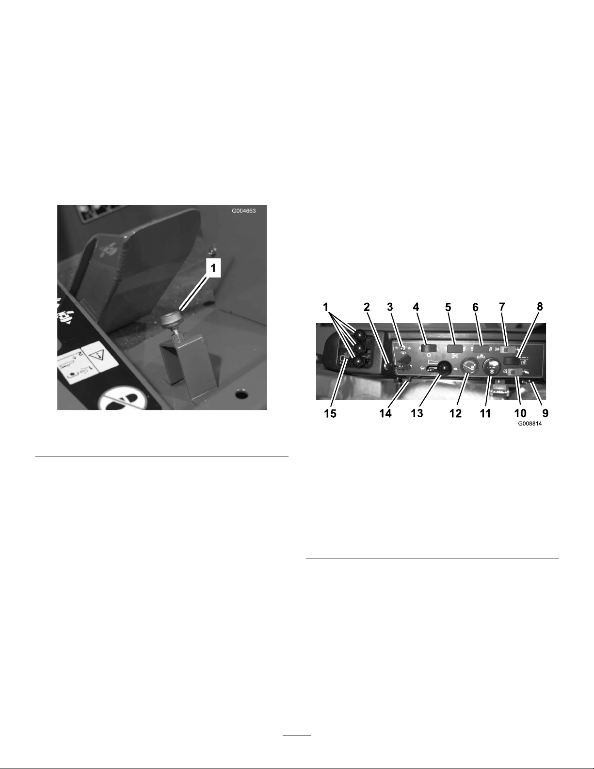
1.Raisetheseatandremovethebatterycover.The
bypassvalveislocatedinfrontofthebattery
(Figure28).
2.Rotatethevalve90degrees(1/4turn)ineither
directiontoopenandallowoiltobypassinternally.
Becauseuidisbypassed,themachinecanbeslowly
movedwithoutdamagingthetransmission.
28
Page 29

Note:Resistancewillbefeltonthevalvewhenitis
movedtotheopenposition.
3.Rotatethevalve90degrees(1/4turn)backto
closethebypassvalvebeforestartingtheengine.
However,donotexceed5to8ft-lb(7to11N⋅m)
torquetoclosethevalve.
Figure28
1.Bypassvalveaccesshole
Figure30
1.Reversefour-wheeldrivepressuretestport
JackingPoints
Therearejackingpointslocatedatthefrontandrear
ofthemachine.
•Ontheframeattheinsideofeachfrontdrivetire
•Atthecenteroftherearaxle
Important:Ifthemachinemusttobe
pushedortowedinreverse,thecheckvalve
inthefour-wheeldrivemanifoldmustalsobe
bypassed.Tobypassthecheckvalve,connect
ahoseassembly(HosePartNo.95-8843,
CouplerFittingNo.95-0985[Qty.2],and
HydraulicFittingNo.340-77[Qty.2])tothe
reversetractionpressuretestport(Figure29)
andthereversefour-wheeldrivepressureport
(Figure30).
Figure29
1.Reversetractionpressuretestport
TieDowns
Therearetiedownslocatedatthefront,rearandsides
ofthemachine.
•Oneachsideoftheframebythesidecuttingunit
liftarms
•Frontcenteroftheoperator’splatform
•Therearbumper
OperatingCharacteristics
Practicedrivingthemachinebecauseithasahydrostatic
transmissionanditscharacteristicsaredifferentthan
manyturfmaintenancemachines.Somepointsto
considerwhenoperatingthetractionunit,cutting
unit,orotherimplementsarethetransmission,engine
speed,loadonthecuttingbladesorotherimplement
components,andtheimportanceofthebrakes.
Tomaintainenoughpowerforthetractionunitand
implementwhileoperating,regulatethetractionpedal
tokeeptheenginespeedhighandsomewhatconstant.
Agoodruletofollowistodecreasethegroundspeed
astheloadontheimplementincreases,andincreasethe
groundspeedastheloaddecreases.
Therefore,allowthetractionpedaltomovebackward
astheenginespeeddecreases,anddepressthepedal
slowlyasthespeedincreases.Bycomparison,when
drivingfromoneworkareatoanother,withnoload
andcuttingunitraised,havethethrottleintheFast
positionanddepressthetractionpedalslowlybutfully
toattainmaximumgroundspeed.
29
Page 30

Thebrakescanbeusedtoassistinturningthemachine.
However,usethemcarefully,especiallyonsoftor
wetgrassbecausetheturfmaybetornaccidentally.
Anotherbenetofthebrakesistomaintaintraction.
Forexample,insomeslopeconditions,theuphillwheel
slipsandlosestraction.Ifthissituationoccurs,depress
theuphillturnpedalgraduallyandintermittentlyuntil
theuphillwheelstopsslipping,thus,increasingtraction
onthedownhillwheel.
OperatingTips
MowWhenGrassisDry
Moweitherinthelatemorningtoavoidthedew,which
causesgrassclumping,orinlateafternoontoavoidthe
damagethatcanbecausedbydirectsunlightonthe
sensitive,freshlymowedgrass.
Useextracarewhenoperatingthemachineonslopes.
Makesurethattheseatlatchisproperlysecuredandthe
seatbeltisbuckled.Driveslowlyandavoidsharpturns
onslopestopreventrollovers.Forsteeringcontrol,the
cuttingunitmustbeloweredwhengoingdownhill.
Thiscuttingunitisdesignedtodriveobjects
intothegroundwheretheyloseenergyquickly
ingrassareas.However,carelessoperation,
combinedwithterrainangle,ricochets,or
improperlypositionedsafetyguardcanleadto
thrownobjectinjuries.
•Whenapersonorpetappearssuddenlyinor
nearthemowingarea,
•Donotresumemowinguntiltheareais
cleared.
Beforestoppingtheengine,disengageallcontrolsand
movethethrottletoSlow .MovingthethrottletoSlow
reduceshighenginespeed,noise,andvibration.Turn
thekeytoOfftostoptheengine.
Beforetransportingthemachine,raisethecuttingunits
andsecurethetransportlatches(Figure31).
stop mo wing
.
SelecttheProperHeight-of-CutSetting
toSuitConditions
Removeapproximately1inch(25mm)ornomorethan
1/3ofthegrassbladewhencutting.Inexceptionally
lushanddensegrass,youmayhavetoraisethe
height-of-cuttothenextsetting.
MowatProperIntervals
Undermostnormalconditionsyouwillneedtomow
approximatelyevery4-5days.Butremember,grass
growsatdifferentratesatdifferenttimes.Thismeans
thatinordertomaintainthesameheight-of-cut,which
isagoodpractice,youwillneedtocutmorefrequently
inearlyspring;asthegrassgrowthrateslowsinmid
summer,cutonlyevery8-10days.Ifyouareunableto
mowforanextendedperiodduetoweatherconditions
orotherreasons,mowrstwiththeheight-of-cutata
highlevel;thenmowagain2-3dayslaterwithalower
heightsetting.
AlwaysMowwithSharpBlades
Asharpbladecutscleanlyandwithouttearingor
shreddingthegrassbladeslikeadullblade.Tearingand
shreddingcausesthegrasstoturnbrownattheedges
whichimpairsgrowthandincreasessusceptibilityto
diseases.
Figure31
1.Transportlatch(wingcuttingunits)
Transporting
Usethetransportlatcheswhentransportingoverlong
distances,roughterrain,orwhentrailering.
AfterOperating
Toensureoptimumperformance,cleantheunderside
ofthemowerhousingaftereachuse.Ifresidueis
allowedtobuildupinthemowerhousing,cutting
performancewilldecrease.
Also,removeanydebriswhichmayhavecollected
betweenthedeckliftcylindersandthefoamdeckpads
(Figure32).
30
Page 31

Figure32
1.Deckliftcylinder
2.Foamdeckpad
CuttingUnitPitch
Werecommendabladepitchof1/4inch(6mm).A
pitchlargerthan1/4inch(6mm)willresultinless
powerrequired,largerclippings,andapoorerquality
ofcut.Apitchlessthan1/4inch(6mm)willresult
inmorepowerrequired,smallerclippingsandabetter
qualityofcut.
31
Page 32

Maintenance
Note:Determinetheleftandrightsidesofthemachinefromthenormaloperatingposition.
RecommendedMaintenanceSchedule(s)
MaintenanceService
Interval
Aftertherst10hours
Aftertherst50hours
Aftertherst200hours
Beforeeachuseordaily
Every50hours
Every100hours
MaintenanceProcedure
•T orquethewheellugnuts.
•Checkthefanbelttension.
•Checkthebladedrivebelttension.
•Changetheengineoilandlter.
•Checktheenginespeed(atidleandfullthrottle).
•Changethefrontplanetarygearoil.
•Changetherearaxleoil.
•Changethehydraulicoil.
•Changethehydraulicoillters.
•Checktheengineoillevel.
•Checkthecoolantlevel.
•Checkthehydraulicuidlevel.
•Checkthetirepressure.
•Checktheaircleanerindicator.
•Checktheinterlockswitchoperation
•Lubricateallgreasettings.
•Checkthebatterylevelandcableconnections.
•Checkthebladedrivebelttension.
•Cleantheundersideofthemowerhousingandunderthebeltcovers.
•Inspectthecoolingsystemhosesandclamps.
•Checkthefanbelttension.
Every150hours
Every200hours
Every400hours
Every800hours
Every2years
•Changetheengineoilandlter.
•T orquethewheellugnuts.
•Servicethesparkarrestormufer
•Checktheplanetarygeardriveoil.
•Checktherearaxlelubricant.
•Checktherearaxlegearboxlubricant.
•Servicetheairlter(iftheindicatorshowsred).
•Inspectthefuellinesandconnections.
•Replacethefuelltercanister.
•Checktheenginespeed(atidleandfullthrottle).
•Drainandcleanthefueltank.
•Changethefrontplanetarygearoil.
•Changetherearaxleoil.
•Checktherearwheeltoe-in.
•Inspectthebladedrivebelts.
•Changethehydraulicoil.
•Changethehydraulicoillters.
•Inspectthecuttingunitcastorwheelassemblies.
•Checkandadjustthevalveclearance.
•Flushthecoolingsystemandreplaceuid.
•Replacemovinghoses.
32
Page 33

Ifyouleavethekeyintheignitionswitch,someonecouldaccidentlystarttheengineandseriously
injureyouorotherbystanders.
Removethekeyfromtheignitionbeforeyoudoanymaintenance.
ServiceIntervalChart
Lubrication
GreasingtheBearingsand
Bushings
Themachinehasgreasettingsthatmustbelubricated
regularlywithNo.2GeneralPurposeLithiumBase
Grease.Ifthemachineisoperatedundernormal
conditions,lubricateallbearingsandbushingsafter
every50hoursofoperationorimmediatelyafterevery
washing.
Bearingsrarelyfailfromdefectsinmaterialsor
workmanship.Themostcommonreasonforfailureis
moistureandcontaminationworkingitswaypastthe
protectiveseals.Bearingsthataregreasedwillrelyupon
regularmaintenancetopurgeharmfuldebrisfromthe
bearingarea.Sealedbearings,suchasthecastorwheel
bearings,relyonaninitialllofspecialgreaseanda
robustintegralsealtokeepcontaminantsandmoisture
outoftherollingelements.
Figure33
Thesealedbearingsrequirenolubricationorshortterm
maintenance.Thisminimizesroutineservicerequired
andreducesthepotentialofturfdamageduetogrease
contamination.Thesesealedbearingpackageswill
providegoodperformanceandlifeundernormaluse,
butperiodicinspectionsofbearingconditionandseal
integrityshouldbeconductedtoavoiddowntime.These
bearingsshouldbeinspectedseasonallyandreplacedif
damagedorworn.Bearingsshouldoperatesmoothly
withnodetrimentalcharacteristicssuchashighheat,
noise,loosenessorindicationsofcorrosion(rust).
Duetotheoperatingconditionsthesebearing/seal
packagesaresubjectto(i.e.sand,turfchemicals,water,
impacts,etc.)theyareconsiderednormalwearitems.
Bearingsthatfailduetocausesotherthandefectsin
materialsorworkmanshiparetypicallynotcovered
underwarranty.
Note:Bearinglifecanbenegativelyaffectedby
improperwashdownprocedures.Donotwash
33
Page 34

downtheunitwhenitisstillhotandavoiddirecting
high-pressureorhighvolumesprayatthebearings.
Thegreasettinglocationsandquantitiesare:
TractionUnit
ServiceInterval:Every50hours
•Brakeshaftpivotbearings(5)(Figure34)
•Tractionpedalpivotbushing(1)(Figure35)
•Frontandrearaxlepivotbushings(2)(Figure36)
•Steeringcylinderballjoints(2)(Figure37)
•Tierodballjoints(2)(Figure37)
•Kingpinbushings(2)(Figure37).
Thetopttingonthekingpinshould
onlybelubricatedannually(2pumps).
Figure36
Figure34
Figure35
Figure37
CenterCuttingUnit
Note:Deckmayhavetoberaisedtoexposethegrease
ttingsforthelatchpivotandthelowerlink.
•Latchpivot(2)(Figure39)
Note:Thelatch(Figure38)mayneedtobe
manuallytrippedtogainaccesstothegreasetting.
Useaprybartocloseandre-openthelatch
34
Page 35

Figure38
1.Latch
Figure39
•Lowerlinkpivot(4)(Figure40)
•Upperlinkpivot(4)(Figure40)
•Castorforkshaftbushings(2)(Figure41)
•Spindleshaftbearings(3)(Figure42)
•Idlerarmpivotbushings(2)(Figure42)
Figure40
Figure42
Figure41
35
Page 36

CenterLiftAssemblies
•Liftarmbushings(2)(Figure43)
•Liftcylinderbushings(4)(Figure43)
•Liftarmballjoints(2)(Figure44)
Figure45
WingCuttingUnits
•Castorforkshaftbushing(1each)(Figure46)
•Spindleshaftbearings(4)
•Idlerarmpivotbushings(1)(locatedontheidler
arm)
Figure43
Figure44
WingLiftAssemblies
Wingliftcylinder(4)(Figure45)
Figure46
36
Page 37

EngineMaintenance
AirCleanerMaintenance
•Checktheaircleanerbodyfordamagewhichcould
causeanairleak.Replaceifdamaged.Checkthe
wholeintakesystemforleaks,damageorloosehose
clamps.
•Servicetheaircleanerlteronlywhentheservice
indicatorrequiresitorevery400hours(more
frequentlyinextremelydustyordirtyconditions).
Changingtheairlterbeforeitisnecessaryonly
increasesthechanceofdirtenteringtheenginewhen
thelterisremoved.
•Besurethecoverisseatedcorrectlyandsealswith
theaircleanerbody.
ServicingtheAirCleaner
ServiceInterval:Beforeeachuseordaily
Every400hours
Checktheaircleanerbodyfordamagewhichcould
possiblycauseanairleak.Replaceadamagedaircleaner
body.
Servicetheaircleanerlterswhentheaircleaner
indicator(Figure47)showsredorevery400hours
(morefrequentlyinextremelydustyordirtyconditions).
Donotover-servicetheairlter.
Figure47
1.Aircleanerindicator3.Aircleanercover
2.Aircleanerlatch
2.Beforeremovingthelter(Figure48),uselow
pressureair(40psi,cleananddry)tohelpremove
largeaccumulationsofdebrispackedbetween
outsideofprimarylterandthecanister.Avoidusing
highpressureairwhichcouldforcedirtthrough
thelterintotheintakearea.Thiscleaningprocess
preventsdebrisfrommigratingintotheintakewhen
theprimarylterisremoved.
Besurethatthecoverissealingaroundtheaircleaner
body.
1.Pullthelatchoutwardandrotatetheaircleanercover
counterclockwise.Removethecoverfromthebody
(Figure47).Cleantheinsideoftheaircleanercover.
Figure48
1.Aircleanerprimarylter
3.Removeandreplacetheprimarylter.Cleaningof
theusedelementisnotrecommendedduetothe
possibilityofdamagetotheltermedia.Inspectthe
newlterforshippingdamage,checkingthesealing
endofthelterandthebody .Donotuseadamaged
element.Insertthenewlterbyapplyingpressureto
theouterrimoftheelementtoseatitinthecanister.
Donotapplypressuretotheexiblecenterofthe
lter.
37
Page 38

Important:Neverattempttocleanthesafety
lter(Figure49).Replacethesafetylterwitha
newoneaftereverythreeprimarylterservices.
2.Removetheoillter(Figure51).Applyalightcoat
ofcleanoiltothenewltersealbeforescrewingit
on.Donotovertighten.
Figure49
1.Aircleanersafetylter
4.Cleanthedirtejectionportlocatedintheremovable
cover.Removetherubberoutletvalvefromthe
cover,cleanthecavityandreplacetheoutletvalve.
5.Installthecoverorientingtherubberoutletvalvein
adownwardposition-betweenapproximately5:00
to7:00whenviewedfromtheend.
6.Resettheindicator(Figure47)ifitshowsred.
ServicingtheEngineOiland
Filter
ServiceInterval:Aftertherst50hours
Every150hours
Changetheoilandlterinitiallyaftertherst50hours
ofoperation;thereafterchangetheoilandlterevery
150hours.
Figure51
1.Engineoillter
3.Addoiltothecrankcase;refertoCheckingthe
EngineOil.
1.Removeeitherdrainplug(Figure50)andlettheoil
owintoadrainpan.Whentheoilstops,installthe
drainplug.
Figure50
1.Engineoildrainplug
38
Page 39

FuelSystem
Maintenance
ServicingtheFuelSystem
Undercertainconditions,dieselfuelandfuel
vaporsarehighlyammableandexplosive.A
reorexplosionfromfuelcanburnyouand
othersandcancausepropertydamage.
2.Loosenthedrainplugonthebottomofthelter
canister.
•Useafunnelandllthefueltankoutdoors,
inanopenarea,whentheengineisoffand
iscold.Wipeupanyfuelthatspills.
•Donotllthefueltankcompletelyfull.Add
fueltothefueltankuntilthelevelis1inch
(25mm)belowthebottomofthellerneck.
Thisemptyspaceinthetankallowsthefuel
toexpand.
•Neversmokewhenhandlingfuel,andstay
awayfromanopenameorwherefuel
fumesmaybeignitedbyaspark.
•Storefuelinaclean,safety-approved
containerandkeepthecapinplace.
FuelTank
ServiceInterval:Every800hours
Drainandcleanthefueltankevery800hours.Also,
drainandcleanthetankiffuelsystembecomes
contaminatedorifthemachinewillbestoredforan
extendedperiodoftime.Usecleanfueltoushout
thetank.
Figure52
1.Waterseparatorltercanister
3.Cleantheareawheretheltercanistermounts.
4.Removetheltercanisterandcleanthemounting
surface.
5.Lubricatethegasketontheltercanisterwithclean
oil.
6.Installtheltercanisterbyhanduntilthegasket
contactsmountingsurface,thenrotateitan
additional1/2turn.
7.Tightenthedrainplugonthebottomofthelter
canister.
BleedingAirfromtheInjectors
1.LoosenthetubeconnectiontotheNumber1
injectornozzleandholderassemblyattheinjection
pump(Figure53).
FuelLinesandConnections
ServiceInterval:Every400hours
Checkthefuellinesandconnectionsevery400hours
oryearly,whichevercomesrst.Inspectthemfor
deterioration,damage,orlooseconnections.
ServicingtheWaterSeparator
ServiceInterval:Every400hours
Drainwaterorothercontaminantsfromwaterseparator
(Figure52)daily.Replaceltercanisterafterevery400
hoursofoperation.
1.Placeacleancontainerunderthefuellter.
Figure53
1.Number1injectornozzle
2.MovethethrottletotheFastposition.
3.TurnthekeyintheignitionswitchtotheStart
positionandwatchthefuelowaroundthe
39
Page 40

connector.TurnthekeytotheOffpositionwhen
solidowisobserved.
4.Tightenthetubeconnectorsecurely .
5.Repeattheprocedureontheremainingnozzles.
ElectricalSystem
Maintenance
Activating,Charging,and
ConnectingtheBattery
Every50hours
BatteryCare
Batterytypeisgroup24.
Important:Beforeweldingonthemachine,
disconnectthenegativecablefromthebatteryto
preventdamagetotheelectricalsystem.
Note:Checkthebatteryconditionweeklyorafterevery
50hoursofoperation.Keeptheterminalsandtheentire
batterycasecleanbecauseadirtybatterywilldischarge
slowly.Tocleanthebattery,washtheentirecasewith
asolutionofbakingsodaandwater.Rinsewithclear
water.Coatthebatterypostsandcableconnectorswith
Grafo112X(skin-over)grease(ToroPartNo.505-47)
orpetroleumjellytopreventcorrosion.
Warning
CALIFORNIA
Proposition65Warning
Batteryposts,terminals,andrelated
accessoriescontainleadandleadcompounds,
chemicalsknowntotheStateofCalifornia
tocausecancerandreproductiveharm.
Washhandsafterhandling.
1.Raisetheseatandsecureitwiththeproprod.
2.Removethebatterycover(Figure54).
40
Page 41

1.Batterycover
Figure54
Batteryterminalsormetaltoolscouldshort
againstmetalcomponentscausingsparks.
Sparkscancausethebatterygassestoexplode,
resultinginpersonalinjury.
•Whenremovingorinstallingthebattery,do
notallowthebatteryterminalstotouchany
metalpartsofthemachine.
•Donotallowmetaltoolstoshortbetween
thebatteryterminalsandmetalpartsofthe
machine.
Incorrectbatterycableroutingcoulddamage
themachineandcablescausingsparks.Sparks
cancausethebatterygassestoexplode,
resultinginpersonalinjury.
•Always
disconnect
thenegative(black)
batterycablebeforedisconnectingthe
positive(red)cable.
Figure55
1.Battery
Chargingthebatteryproducesgassesthatcan
explode.
Neversmokenearthebatteryandkeepsparks
andamesawayfrombattery.
•Always
connect
thepositive(red)battery
cablebeforeconnectingthenegative(black)
cable.
4.CoatbothbatteryconnectionswithGrafo112X
(skin-over)grease,T oroPartNo.505-47,petroleum
jelly,orlightgreasetopreventcorrosion.Slidethe
rubberbootoverthepositiveterminal.
5.Installthebatterycover.
Fuses
Thereare8fusesintheelectricalsystem.Theyare
locatedbelowtheoperatorscontrolpanel(Figure56
andFigure57).
3.Removetherubberbootfromthepositiveterminal
andinspectthebattery.
41
Page 42

DriveSystem
Maintenance
ChangingthePlanetaryGear
DriveOil
ServiceInterval:Aftertherst200hours
Every800hours
Changetheoilinitiallyafterrst200hoursofoperation.
Thereafterchangetheoilevery800hours,oryearly ,
whicheveroccursrst.UseahighqualitySAE85W-140
gearlube.
1.Withthemachineonalevelsurface,positionthe
Figure56
1.Fuses
wheelsothatthecheck/drainplug(Figure58)isat
thelowestposition.
Figure57
1.Poweroutlet
2.Seatswitch
3.Ignitionswitch7.Fan
4.PowerTakeOff(PTO)
5.Startersolenoid
6.LightKit
8.Powerseat
Figure58
1.Check/drainplug
2.Placeadrainpanunderthehub,removetheplug,
andallowtheoiltodrain.
3.Whenalloftheoilhasdrained,positionthewheel
sothattheplugholeisatthetenortwoo’clock
position.
4.Placeadrainpanunderthebrakehousingonthe
othersideofthewheel(Figure59).
5.Removetheplugfromthebottomofthehousing
andallowtheoiltodrain.
6.Whenalloftheoilhasdrained,installtheplugin
thehousing.
7.Removecheckplugfrombrakehousing(Figure59).
8.AddhighqualitySAE85W-140wtgearlubetothe
planetaryllhole(atthetenortwoo’clockposition)
andtothecheckholeinbrakehousinguntilthe
42
Page 43

levelisuptothebottomoftheplanetaryandbrake
housingcheckholes.Capacityisapproximately16
oz.(0.5l).
9.Installtheplugs.
10.Repeattheprocedureontheoppositegearassembly.
Figure59
1.Brakehousing
2.Drainplug
3.Checkplug
Figure60
1.Drainpluglocation
5.Cleantheareaaroundthedrainplugonthebottom
ofthegearbox(Figure61).
6.Removethedrainplugfromthegearboxandallow
theoiltodrainintoapan.Removethellplugto
easeindrainingoftheoil.
ChangingtheRearAxle
Lubricant
ServiceInterval:Aftertherst200hours
Every800hours
Changetheoilinitiallyaftertherst200hoursof
operationandevery800hoursofoperationthereafter.
1.Positionthemachineonalevelsurface.
2.Cleantheareaaroundthe3drainplugs;1oneach
endand1inthecenter(Figure60).
3.Removethecheckplugstoeaseindrainingoftheoil.
4.Removethedrainplugsandallowtheoiltodrain
intothepans.
Figure61
1.Drainplug
7.Addenoughoiltobringtheleveluptothebottom
ofthecheckplugholes;refertoCheckingtheRear
AxleLubricant,andCheckingtheRearAxleGear
BoxLubricant.
8.Installtheplugs.
43
Page 44

CheckingtheRearWheel
Toe-In
ServiceInterval:Every800hours
CoolingSystem
Maintenance
Afterevery800operatinghoursorannually ,checkthe
rearwheeltoe-in.
1.Measurethecenter-to-centerdistance(ataxleheight)
atthefrontandrearofthesteeringtires.Thefront
measurementmustbe1/4inch(6mm)lessthanthe
rearmeasurement.
2.Toadjust,loosentheclampsatbothendsofthetie
rods.
3.Rotatethetierodendtomovethefrontofthetire
inwardoroutward.
4.Tightenthetierodclampswhentheadjustmentis
correct.
ChangingtheFrontTires
1.Lowerthewingcuttingunitstotheground.
2.Raisethefrontofthemachineseveralinchesoffthe
groundandsupportw/jackstands.
3.RefertoPivoting(Tilting)theFrontCuttingUnit
UprightinMowerMaintenance.
ServicingtheEngineCooling
System
ServiceInterval:Every100hours
Every2years
Thismachineisequippedwithahydraulicallydrivenfan
drivesystemthatautomatically(ormanually)reverses
toreduceradiatorandscreendebrisbuild-up.While
thisfeaturecanhelpreducethetimerequiredtoclean
radiatorsandcoolers,itdoesnoteliminatetheneedfor
routinecleaning.Periodiccleaningandinspectionof
theradiatorisstillrequired.
Removedebrisfromtheoilcoolerandradiatordaily.
Cleanthemmorefrequentlyindirtyconditions.
1.Turntheengineoffandraisethehood.Cleanthe
engineareathoroughlyofalldebris.
2.Removetheknobs(Figure62)securingtheoilcooler
totheframe.
4.PivotCuttingunitforwardtoallowremovalofthe
tirerequiringservice.
Figure62
1.Knobs
3.Pivottheoilcoolerrearward.Cleanbothsidesofthe
oilcoolerandradiatorarea(Figure63)thoroughly
withcompressedair.Startfromthefrontandblow
thedebrisouttowardstheback.Thencleanfrom
thebacksideandblowtowardsthefront.Repeat
procedureseveraltimesuntilallchaffanddebrisis
removed
Important:Cleaningtheradiatororoilcooler
withwatercanpromoteprematurecorrosion
anddamagetocomponents.
44
Page 45

Figure63
1.Oilcooler
4.Pivottheoilcoolerbackintoposition.Secureitto
theframewiththeknobsandclosethehood.
2.Radiator
BrakeMaintenance
AdjustingtheServiceBrakes
Adjusttheservicebrakeswhenthereismorethan1inch
(25mm)of“freetravel”ofthebrakepedal,orwhenthe
brakesdonotworkeffectively.Freetravelisthedistance
thebrakepedalmovesbeforebrakingresistanceisfelt.
1.Disengagethelockinglatchfromthebrakepedalsso
thatbothpedalsworkindependentlyofeachother.
2.Toreducefreetravelofthebrakepedals,tighten
thebrakes:
A.Loosenthefrontnutonthethreadedendofthe
brakecable.
B.Tightentherearnuttomovethecablebackward
untilthebrakepedalshave1/2to1inch(13to
25mm)offreetravel.
C.Tightenthefrontnutsafterthebrakesare
adjustedcorrectly.
45
Page 46

BeltMaintenance
ServicingtheAlternatorBelt
ServiceInterval:Aftertherst10hours
Every100hours
Checktheconditionandtensionofthebelts(Figure64)
afterevery100operatinghours.
1.Propertensionwillallow3/8inch(10mm)
deectionwhenaforceof10lbisappliedonthe
beltmidwaybetweenthepulleys.
2.Ifthedeectionisnot3/8inch(10mm),loosen
thealternatormountingbolts(Figure64).Increase
ordecreasethealternatorbelttensionandtighten
thebolts.Checkthedeectionofthebeltagainto
ensurethatthetensioniscorrect.
Figure65
1.Belt4.Beltguide
2.Eyebolt5.Flangenut
3.Extensionspring
6.Stopbolt
ReplacingtheBladeDriveBelt
ServiceInterval:Every800hours
Figure64
1.Alternator2.Mountingbolt
Re-tensioningtheBladeDrive
Belts
ServiceInterval:Aftertherst10hours
Every50hours
Checktheconditionandtensionofthecuttingunitdrive
beltsinitiallyafter8hoursofoperationandevery50
operatinghoursthereafter.
Whenproperlytensioned,theextensionspring(hook
tohook)measurementshouldbeapproximately3.50
±.25inch(inside).Oncethecorrectspringtensionis
attained,adjustthestopbolt(carriagebolt)untilthereis
approximately.125+.060/-.000inchclearancebetween
theheadoftheboltandtheidlerarm(Figure65).
Thebladedrivebelt,tensionedbythespringloaded
idlerpulley,isverydurable.However,aftermanyhours
ofuse,thebeltwillshowsignsofwear.Signsofaworn
beltare:squealingwhenbeltisrotating,bladesslipping
whencuttinggrass,frayededges,burnmarksandcracks.
Replacethebeltifanyoftheseconditionsareevident.
1.Lowerthecuttingunittotheshopoor.Remove
thebeltcoversfromthetopofthecuttingunitand
setthecoversaside.
2.Loosentheeyeboltallowingtheremovalofthe
extensionspring(Figure65).
3.Loosentheangenutsecuringthestopbolttothe
mountingtab.Backoffthenutenoughtoallowthe
idlerarmtopassbythestopbolt(Figure65).Move
theidlerpulleyawayfromthebelttoreleasebelt
tension.
Note:Ifthestopboltiseverremovedfromthe
mountingtab,makesureitisreinstalledinthehole
thatalignsthestopboltheadwiththeidlerarm.
4.Removetheboltssecuringthehydraulicmotorto
thecuttingunit(Figure66).Liftthemotoroffofthe
cuttingunitandlayitontopofthecuttingunit.
Note:Makesurethebeltispositionedonthespring
sideofthebeltguide(Figure65).
46
Page 47

Figure66
1.Hydraulicmotor2.Mountingbolts
5.Removetheoldbeltfromaroundthespindlepulleys
andidlerpulley.
6.Routethenewbeltaroundthespindlepulleysand
idlerpulleyassembly .
ControlsSystem
Maintenance
AdjustingtheThrottleCable
ServiceInterval:Aftertherst50hours
Every400hours
Adjustthethrottlecable(Figure67)sothatthegovernor
leverontheenginecontactsthelowandhighspeedset
boltsbeforethethrottlelevercontactstheslotinthe
controlpanel.
7.Positionthehydraulicmotoronthecuttingunitafter
routingthebeltaroundthepulleys.Mountthemotor
tothecuttingunitwiththeboltspreviouslyremoved.
Note:Makesurethebeltispositionedonthespring
sideofthebeltguide(Figure65).
8.Reconnecttheextensionspring(Figure65)tothe
eyeboltandtensionthebeltasfollows:
•Whenproperlytensioned,theextension
spring(hooktohook)measurementshouldbe
approximately3.50±.25inch(inside).
•Oncethecorrectspringtensionisattained,
adjustthestopbolt(carriagebolt)untilthereis
approximately.125+.060/-.000inchclearance
betweentheheadoftheboltandtheidlerarm.
Figure67
1.Throttlecable
AdjustingtheTractionPedal
Linkage
Thetractionpedalshouldreachfullstrokeatthesame
timeitmakescontactwiththestop.Ifitdoesnot,
performthefollowingprocedure:
1.Parkthemachineonalevelsurface,stoptheengine,
andlowerthecuttingunitstotheoor.Removethe
ignitionkey .
2.Checkthetractionpedalstopadjustment.The
distancefromthetopofthestandtothetopof
thestopmustbe1-1/2inch(38mm)(Figure68).
Loosenthenutsandadjust,asrequired.
47
Page 48

Figure68
1.Tractionpedalstop
2.Stand
3.Loosenthejamnutsontherodendandadjustthe
tractionrodlength(Figure69)sothatthepedal
contactsthepedalstopwhenthepumpleverreaches
fullstroke.Securethejamnuts.
HydraulicSystem
Maintenance
ChangingtheHydraulicFluid
ServiceInterval:Aftertherst200hours
Every800hours
Changethehydraulicuidafterevery800operating
hours,innormalconditions.Iftheuidbecomes
contaminated,contactyourlocalT orodistributor
becausethesystemmustbeushed.Contaminateduid
looksmilkyorblackwhencomparedtocleanoil.
1.Turntheengineoffandraisethehood.
2.Loosenthedrainvalveonthebottomofthe
reservoirandletthehydraulicuidowintolarge
drainpan.Closethevalvewhenthehydraulicuid
stopsdraining.
3.Fillthereservoir(Figure69)withapproximately8
gallons(30l)ofhydraulicuid;refertoChecking
theHydraulicFluid.
Figure69
1.Rodend3.Neutralreturnspring
assembly
2.Tractionrod4.Jamnut
4.Turnthekeyswitchtotherunpositionwithout
startingtheengine.Loosenthejamnutandadjust
theneutralreturnspringassemblyshaftlengthuntil
theaudiblealarmbeginstosound.Securethejam
nut.
5.Turnthekeyswitchoff.
Important:Useonlythehydraulicuids
specied.Otheruidscouldcausesystem
damage.
Figure70
1.Hydraulicreservoir
4.Installthereservoircap.Starttheengineanduseall
ofthehydrauliccontrolstodistributehydraulicuid
throughoutthesystem.Alsocheckforleaks;then
stoptheengine.
5.Checktheuidlevelandaddenoughtoraiselevel
theleveltotheFULLmarkonthedipstick.Donot
overll.
48
Page 49

ReplacingtheHydraulicFilters
ServiceInterval:Aftertherst200hours
Every800hours
Changethe2hydraulicltersinitiallyaftertherst200
operatinghours.Thereafter,changetheltersafter
every800operatinghours,innormalconditions.
UseTororeplacementlters(PartNo.94-2621forthe
leftsideofthemachineand75-1310fortherightside
ofthemachine).
Important:Useofanyotherltermayvoidthe
warrantyonsomecomponents.
1.Positionthemachineonalevelsurface,lowerthe
cuttingunits,stoptheengine,engagetheparking
brakes,andremovetheignitionkey.
2.Cleantheareaaroundtheltermountingarea.Place
adrainpanunderthelterandremovethelter
(Figure71).
Hydraulicuidescapingunderpressurecan
penetrateskinandcauseinjury.
•Makesureallhydraulicuidhosesand
linesareingoodconditionandallhydraulic
connectionsandttingsaretightbefore
applyingpressuretothehydraulicsystem.
•Keepyourbodyandhandsawayfrompin
holeleaksornozzlesthatejecthighpressure
hydraulicuid.
•Usecardboardorpapertondhydraulic
leaks.
•Safelyrelieveallpressureinthehydraulic
systembeforeperforminganyworkonthe
hydraulicsystem.
•Seekimmediatemedicalattentionifuid
isinjectedintoskin.
AdjustingtheCounterbalance
Figure71
3.Lubricatethenewltergasketandllthelterwith
hydraulicuid.
4.Ensurethattheltermountingareaisclean.Screw
thelteronuntilthegasketcontactsthemounting
plate;thentightenthelteranadditional1/2turn.
5.Starttheengineandletitrunforabouttwominutes
topurgeairfromthesystem.Stoptheengineand
checkforleaks.
CheckingtheHydraulicLines
andHoses
Pressure
Thecounterbalancetestport(Figure72)isused
totestthepressureinthecounterbalancecircuit.
Recommendedcounterbalancepressureis470psi(3241
kPa).T oadjustthecounterbalancepressure,rotatethe
adjustingscrew(Figure72)clockwisetoincreasethe
pressureorcounterclockwisetodecreasethepressure.
Note:Allthreesidecuttingunitscastorwheelsshould
remainonthegroundwithcounterbalanceapplied.
Figure72
1.Counterbalancetestport2.Counterbalanceadjusting
screw
ServiceInterval:Every2years
Inspectthehydrauliclinesandhosesdailyfor
leaks,kinkedlines,loosemountingsupports,wear,
loosettings,weatherdeterioration,andchemical
deterioration.Makeallnecessaryrepairsbefore
operating.
AdjustingtheCuttingUnit
FlowControl
Theowcontrolvalve(Figure73)isusedtoadjustthe
rateatwhichthecuttingunitlowers.
49
Page 50

1.Flowcontrolvalve
Figure73
MowerMaintenance
Pivoting(Tilting)theFront
CuttingUnitUpright
Note:Althoughnotneededfornormalmaintenance
procedures,thefrontcuttingunitcanbepivoted(tilted)
toanuprightposition.Shouldyoudesiretotiltthe
cuttingunit,proceedasfollows:
1.Raisethecenterandwingcuttingunitsslightlyoffof
theoor,settheparkingbrake,andstoptheengine.
Removetheignitionkey .
2.Removethehairpincottersecuringdamperstolift
arms(Figure74).Pivotdampertowarddeckhousing.
Figure74
1.Damper2.Hairpincotter
3.Removethehairpincotterandclevispinsecuring
theheight-of-cutchainstotherearofthecutting
unit(Figure75).
Figure75
1.Height-of-cutchain
4.Starttheengineandslowlyraisethecentercutting
unit.
5.Slowlyraiseeachwingcuttinguntilthecenterof
gravityshiftsandthedeckstartstorotateintothe
uprightposition.Stoptheengineandremovethe
ignitionkey .
50
Page 51

PivotingtheFrontCuttingUnit
Down
1.Slowlylowerwingcuttingunitsuntilthecenterof
gravityshiftsandthecentercuttingunitrotates
downward.
2.Sitontheseat,starttheengine,andlowerthecenter
cuttingunituntilitisslightlyoffoftheoor.
3.Securetheheight-of-cutchainstotherearofthe
cuttingunit.
4.Pivotdampersupwardintopositionandsecurewith
clevispinandcotterpin.
1.Height-of-cutchain
Figure76
2.U-bolt
AdjustingtheCuttingUnit
Pitch
MeasuringtheCuttingUnitPitch
Cuttingunitpitchisthedifferenceinheight-of-cutfrom
thefrontofthebladeplanetothebackoftheblade
plane.Tororecommendsabladepitchof1/4inch(6
mm).Thatisthebackofthebladeplaneis1/4inch(6
mm)higherthanthefront.
1.Positionthemachineonalevelsurfaceontheshop
oor.
2.Setthecuttingunittothedesiredheight-of-cut.
3.Rotate1bladesothatitpointsstraightforward.
4.Usingashortruler,measurefromtheoortothe
fronttipoftheblade.Rotatethebladetiptotherear
andmeasurefromtheoortothetipoftheblade.
5.Subtractthefrontdimensionfromtherear
dimensiontocalculatethebladepitch.
AdjustingtheWingCuttingUnits
1.Removethecapscrewsandnutssecuringthecastor
armtothecastorfork(Figure77).
2.Repositiontheshims,asrequired,toraiseorlower
thecastorwheeluntilthecuttingunithasthecorrect
pitch.
3.Installthecapscrewsandnuts.
AdjustingtheFrontCuttingUnit
1.Loosenthejamnutsonthetoporbottomofthe
height-of-cutchainU-bolt(Figure76).
2.Adjusttheothersetofnutstoraiseorlowertherear
ofthecuttingunitandattainthecorrectcuttingunit
pitch.
3.Tightenthejamnuts.
Figure77
1.Castorwheel4.Shims
2.Tensioningcap5.Axlemountingholes
3.Spacers
51
Page 52

ServicingtheCastorArm
Bushings
Thecastorarmshavebushingspressedintothetopand
bottomofthetubeandaftermanyhoursofoperation,
thebushingswillwear.Tocheckthebushings,movethe
castorforkbackandforthandfromsidetoside.Ifthe
castorspindleislooseinsidethebushings,thebushings
arewornandmustbereplaced.
1.Raisethecuttingunitsothatthewheelsareoffof
theoor.Blockthecuttingunitsothatitcannot
accidentallyfall.
2.Removethetensioningcap,spacer(s),andthrust
washerfromthetopofthecastorspindle.
orthecastorpivotarm(Figure80).Graspthecastor
wheelandslidetheboltoutoftheforkorpivotarm.
3.Pullthecastorspindleoutofthemountingtube.
Allowthethrustwasherandspacer(s)toremainon
thebottomofthespindle.
4.Insertapinpunchintothetoporbottomofthe
mountingtubeanddrivethebushingoutofthetube
(Figure78).Alsodrivetheotherbushingoutofthe
tube.Cleantheinsideofthetubestoremovedirt.
Figure78
1.Castorarmtube
2.Bushings
5.Applygreasetotheinsideandoutsideofthenew
bushings.Usingahammerandatplate,drivethe
bushingsintothemountingtube.
6.Inspectthecastorspindleforwearandreplaceitif
itisdamaged.
Figure79
1.Castorwheel
2.Castorfork
1.Castorwheel
2.Castorpivotarm
3.Bearing
4.Bearingspacer
Figure80
3.Bearing
4.Bearingspacer
2.Removethebearingfromthewheelhuband
allowthebearingspacertofallout(Figure79and
Figure80).Removethebearingfromtheopposite
sideofthewheelhub.
7.Pushthecastorspindlethroughthebushingsand
mountingtube.Slidethethrustwasherandspacer(s)
ontothespindle.Installthetensioningcaponthe
castorspindletoretainallpartsinplace.
ServicingtheCastorWheels
andBearings
ServiceInterval:Every800hours
1.Removethelocknutfromtheboltholdingthecastor
wheelassemblybetweenthecastorfork(Figure79)
3.Checkthebearings,spacer,andinsideofthewheel
hubforwear.Replaceanydamagedparts.
4.Toassemblethecastorwheel,pushthebearinginto
thewheelhub.Wheninstallingthebearings,press
ontheouterraceofthebearing.
5.Slidethebearingspacerintothewheelhub.Pushthe
otherbearingintotheopenendofthewheelhubto
captivatethebearingspacerinsidethewheelhub.
6.Installthecastorwheelassemblybetweenthecastor
forkandsecureitinplacewiththeboltandlocknut.
52
Page 53

ReplacingtheCuttingUnit
HingeCovers
BladeMaintenance
Thehingecoverpreventsdebrisfromescapingathinge
pointsbetweencuttingunits.Ifcover(s)everbecome
damagedorwormtheymustbereplaced.
Figure81
1.Hingecover
CheckingforaBentBlade
1.Positionthemachineonalevelsurface.Raisethe
cuttingunit,engagetheparkingbrake,putthe
tractionpedalinneutral,putthePTOleverin
theOffposition,stoptheengine,andremovethe
ignitionkey .Blockthecuttingunittopreventitfrom
accidentallyfalling.
2.Rotatethebladeuntiltheendsfaceforwardand
backward(Figure82).Measurefromtheinsideof
thecuttingunittothecuttingedgeatthefrontofthe
blade.Rememberthisdimension.
Figure82
3.Rotatetheoppositeendofthebladeforward.
Measurebetweenthecuttingunitandcuttingedge
ofthebladeatthesamepositionasinstep2.The
differencebetweenthedimensionsobtainedinsteps
2and3mustnotexceed1/8inch(3mm).Ifthe
dimensionexceeds1/8inch(3mm),thebladeis
bentandmustbereplaced;refertoRemovingand
InstallingtheCutterBlade.
RemovingandInstallingthe
CutterBlade(s)
Theblademustbereplacedifasolidobjectishit,the
bladeisoutofbalance,orifthebladeisbent.Always
usegenuineTororeplacementbladestobesureofsafety
andoptimumperformance.Neverusereplacement
bladesmadebyothermanufacturersbecausetheycould
bedangerous.
1.Raisethecuttingunittothehighestposition,engage
theparkingbrake,stoptheengine,andremovethe
ignitionkey .Blockthecuttingunittopreventitfrom
accidentallyfalling.
53
Page 54

2.Grasptheendofthebladeusingaragorthickly
paddedglove.Removethebladebolt,anti-scalpcup,
andbladefromthespindleshaft(Figure83).
3.Installtheblade,anti-scalpcup,andbladebolt.
Tightenthebladeboltto85to110ft-lb(115to149
N⋅m).
Important:Thecurvedpartoftheblademust
bepointingtowardtheinsideofthecuttingunit
toensurepropercutting.
Note:Afterstrikingaforeignobject,torqueallthe
spindlepulleynutsto130to150ft-lb(176to203
N⋅m).
Figure83
1.Bladebolt2.Anti-scalpcup
wearsdown,thequality-of-cutwilldegradesomewhat,
althoughthecuttingedgesaresharp.Thecuttingedge
oftheblademustbesharpsothatthegrassiscutrather
thantorn.Adullcuttingedgeisevidentwhenthetips
ofthegrassappearbrownandshredded.Sharpenthe
cuttingedgestocorrectthiscondition.
1.Positionthemachineonalevelsurface.Raisethe
cuttingunit,engagetheparkingbrake,putthe
tractionpedalinneutral,putthePTOleverin
theOffposition,stoptheengine,andremovethe
ignitionkey .
2.Examinethecuttingendsofthebladecarefully,
especiallywheretheatandcurvedpartsofthe
blademeet(Figure84).Sincesandandabrasive
materialcanwearawaythemetalthatconnects
theatandcurvedpartsoftheblade,checkthe
bladebeforeusingthemower.Ifwearisnoticed
(Figure84),replacetheblade.
InspectingandSharpeningthe
CutterBlade(s)
Awornordamagedbladecanbreak,and
apieceofthebladecouldbethrowninto
theoperator’sorbystander’sarea,resulting
inseriouspersonalinjuryordeath.Trying
torepairadamagedblademayresultin
discontinuedsafetycerticationoftheproduct.
•Inspectthebladeperiodicallyforwearor
damage.
•Nevertrytostraightenabladethatisbent
orweldabrokenorcrackedblade.
•Replaceawornordamagedblade.
Twoareasmustbeconsideredwhencheckingand
servicingthecutterblade-thesailandthecuttingedge.
Bothcuttingedgesandthesail,whichistheturned
upportionoppositethecuttingedge,contributetoa
goodquality-of-cut.Thesailisimportantbecauseit
liftsthegrassupstraight,therebyproducinganeven
cut.However,thesailwillgraduallyweardownduring
operation,andthisconditionisnormal.Asthesail
54
Page 55

Ifthebladeisallowedtowear,aslotwillform
betweenthesailandatpartoftheblade
(Figure84).Eventuallyapieceoftheblade
maybreakoffandbethrownfromunderthe
housing,possiblyresultinginseriousinjuryto
youorbystanders.
•Inspectthebladeperiodicallyforwearor
damage.
•Nevertrytostraightenabladethatisbent
orweldabrokenorcrackedblade.
•Replaceawornordamagedblade.
Figure85
1.Sharpenatoriginalangle
Figure84
1.CuttingEdge3.Wear/slotForming
2.CurvedArea4.Crack
3.Examinethecuttingedgesofalloftheblades.
Sharpenthecuttingedgesiftheyaredullornicked.
Sharpenonlythetopofthecuttingedgeand
maintaintheoriginalcuttingangletomakesure
ofsharpness(Figure85).Thebladewillremain
balancedifthesameamountofmetalisremoved
frombothcuttingedges.
Note:Removethebladesandsharpenthemona
grinder.Aftersharpeningthecuttingedges,install
thebladewiththeanti-scalpcupandbladebolt;refer
toRemovingandInstallingtheCutterBlade(s).
CorrectingCuttingUnit
Mismatch
Ifthereismismatchbetweentheblades,onasingle
cuttingunit,thegrasswillappearstreakedwhenitiscut.
Thisproblemcanbecorrectedbymakingsurethatthe
bladesarestraightandallofthebladesarecuttingon
thesameplane.
1.Usinga3foot(1meter)longcarpenterslevel,nd
alevelsurfaceontheshopoor.
2.Raisetheheight-of-cuttothehighestposition;refer
toAdjustingtheHeight-Of-Cut.
3.Lowerthecuttingunitontotheatsurface.Remove
thecoversfromthetopofthecuttingunit.
4.Loosentheangenutsecuringtheidlerpulleyto
releasethebelttension.
5.Rotatethebladesuntiltheendsfaceforwardand
backward.Measurefromtheoortothefronttipof
thecuttingedge.Rememberthisdimension.Then
rotatethesamebladesothattheoppositeendis
forward,andmeasureagain.Thedifferencebetween
55
Page 56

thedimensionsmustnotexceed1/8inch(3mm).
Ifthedimensionexceeds1/8inch(3mm),replace
thebladebecauseitisbent.Makesuretomeasure
alloftheblades.
SparkArrestor
Maintenance
6.Comparethemeasurementsoftheouterbladeswith
thecenterblade.Thecenterblademustnotbemore
than3/8inch(10mm)lowerthantheouterblades.
Ifthecenterbladeismorethan3/8inch(10mm)
lowerthantheouterblades,proceedtostep7and
addshimsbetweenthespindlehousingandthe
bottomofthecuttingunit.
7.Removethebolts,atwashers,lockwashers,and
nutsfromtheouterspindleintheareawhere
theshimsmustbeadded.Toraiseorlowerthe
blade,addashim,PartNo.3256-24,betweenthe
spindlehousingandthebottomofthecuttingunit.
Continuetocheckthealignmentofthebladesand
addshimsuntilthetipsofthebladesarewithinthe
requireddimension.
Important:Donotusemorethanthreeshimsat
anyoneholelocation.Usedecreasingnumbers
ofshimsinadjacentholesifmorethanoneshim
isaddedtoanyoneholelocation.
8.Adjusttheidlerpulleyandinstallthebeltcovers.
ServicingtheSparkArrestor
Mufer
ServiceInterval:Every200hours
Every200hoursoperation,clearthemuferofcarbon
buildup.
1.Removethepipeplugfromtheclean-outportatthe
lowersideofthemufer.
Themufermaybehotandcouldcauseinjury.
Becarefulwhileworkingaroundthemufer.
2.Starttheengine.Plugthenormalmuferexitwitha
blockofwoodormetalplatesothattheexhaustow
willbeforcedoutoftheclean-outport.Continueto
blocktheexituntilcarbondepositsceasecoming
outoftheport.
Donotstandinlinewiththeclean-outport.
Alwayswearsafetyglasses.
3.Stoptheengineandreplacethepipeplug.
56
Page 57

Storage
PreparingforSeasonal
Storage
TractionUnit
1.Thoroughlycleanthetractionunit,cuttingunits,and
theengine.
2.Checkthetirepressure;refertoCheckingtheTire
PressureprocedureinOperation,page18.
3.Checkallfastenersforlooseness;tightenas
necessary.
4.Greaseoroilallgreasettingsandpivotpoints.
Wipeupanyexcesslubricant.
5.Lightlysandandusetouch-uppaintonpaintedareas
thatarescratched,chipped,orrusted.Repairany
dentsinthemetalbody .
6.Servicethebatteryandcablesasfollows:
A.Removethebatteryterminalsfromthebattery
posts.
B.Cleanthebattery,terminals,andpostswitha
wirebrushandbakingsodasolution.
C.Coatthecableterminalsandbatterypostswith
Grafo112Xskin-overgrease(ToroPartNo.
505-47)orpetroleumjellytopreventcorrosion.
D.Slowlyrechargethebatteryevery60daysfor24
hourstopreventleadsulfationofthebattery.
Engine
1.Draintheengineoilfromtheoilpanandinstallthe
drainplug.
2.Removeanddiscardtheoillter.Installanewoil
lter.
3.Relltheoilpanwith10qts(9.5l)ofSAE15W-40
CH-4,CI-4,orhighermotoroil.
4.Starttheengineandrunitatidlespeedfor
approximatelytwominutes.
5.Stoptheengine.
6.Flushthefueltankwithfresh,cleandieselfuel.
7.Secureallofthefuelsystemttings.
8.Thoroughlycleanandservicetheaircleaner
assembly.
9.Sealtheaircleanerinletandtheexhaustoutletwith
weatherprooftape.
10.Checktheantifreezeprotectionandadda50/50
solutionofwaterandethyleneglycolanti-freezeas
neededfortheexpectedminimumtemperaturein
yourarea.
57
Page 58

Schematics
ElectricalSchematic,sheet1(Rev.B)
58
Page 59

ElectricalSchematic,sheet2(Rev.A)
59
Page 60

HydraulicSchematic(Rev.A)
60
Page 61

Notes:
61
Page 62

Notes:
62
Page 63

Notes:
63
Page 64

Toro General Commercial Products Warranty
A Two-Year Limited Warranty
Conditions and Products Covered
The Toro Company and its affi liate, Toro Warranty Company,
pursuant to an agreement between them, jointly warrant your Toro
Commercial Product (“Product”) to be free from defects in materials or workmanship for two years or 1500 operational hours*,
whichever occurs fi rst. This warranty is applicable to all products
with the exception of Aerators (refer to separate warranty statements for these products). Where a warrantable condition exists,
we will repair the Product at no cost to you including diagnosis,
labor, parts, and transportation. This warranty begins on the date
the Product is delivered to the original retail purchaser.
* Product equipped with hour meter
Instructions for Obtaining Warranty Service
You are responsible for notifying the Commercial Products Distributor or Authorized Commercial Products Dealer from whom
you purchased the Product as soon as you believe a warrantable
condition exists. If you need help locating a Commercial Products
Distributor or Authorized Dealer, or if you have questions regarding your warranty rights or responsibilities, you may contact us at:
Toro Commercial Products Service Department
Toro Warranty Company
8111 Lyndale Avenue South
Bloomington, MN 55420-1196
952-888-8801
E-mail: commercial.warrnty@toro.com
Owner Responsibilities
As the Product owner, you are responsible for required maintenance and adjustments stated in your Operator’s Manual.
Failure to perform required maintenance and adjustments can be
grounds for disallowing a warranty claim.
Items and Conditions Not Covered
Not all product failures or malfunctions that occur during the
warranty period are defects in materials or workmanship. This
warranty does not cover the following:
Product failures which result from the use of non-Toro
•
replacement parts, or from installation and use of add-on,
or modifi ed non-Toro branded accessories and products. A
separate warranty may be provided by the manufacturer of
these items.
Product failures which result from failure to perform recom-
•
mended maintenance and/or adjustments. Failure to properly
maintain your Toro product per the Recommended Maintenance listed in the Operator’s Manual can result in claims for
warranty being denied.
Product failures which result from operating the Product in an
•
abusive, negligent or reckless manner.
Parts subject to consumption through use unless found to be
•
defective. Examples of parts which are consumed, or used
up, during normal Product operation include, but are not limited to, brakes pads and linings, clutch linings, blades, reels,
bed knives, tines, spark plugs, castor wheels, tires, fi lters,
belts, and certain sprayer components such as diaphragms,
nozzles, and check valves, etc.
Failures caused by outside infl uence. Items considered to be
•
outside infl uence include, but are not limited to, weather, stor-
age practices, contamination, use of unapproved coolants,
Countries Other than the United States or Canada
Customers who have purchased Toro products exported from the United States or Canada should contact their Toro Distributor (Dealer)
to obtain guarantee policies for your country, province, or state. If for any reason you are dissatisfi ed with your Distributor’s service or
have diffi culty obtaining guarantee information, contact the Toro importer.
lubricants, additives, fertilizers, water, or chemicals, etc.
Normal noise, vibration, wear and tear, and deterioration.
•
Normal “wear and tear” includes, but is not limited to, dam-
•
age to seats due to wear or abrasion, worn painted surfaces,
scratched decals or windows, etc.
Parts
Parts scheduled for replacement as required maintenance are warranted for the period of time up to the scheduled replacement time
for that part. Parts replaced under this warranty are covered for the
duration of the original product warranty and become the property
of Toro. Toro will make the fi nal decision whether to repair any ex-
isting part or assembly or replace it. Toro may use remanufactured
parts for warranty repairs.
Note Regarding Deep Cycle Battery Warranty:
Deep cycle batteries have a specifi ed total number of kilowatt-
hours they can deliver during their lifetime. Operating, recharging,
and maintenance techniques can extend or reduce total battery
life. As the batteries in this product are consumed, the amount
of useful work between charging intervals will slowly decrease
until the battery is completely worn out. Replacement of worn out
batteries, due to normal consumption, is the responsibility of the
product owner. Battery replacement may be required during the
normal product warranty period at owner’s expense.
Maintenance is at Owner’s Expense
Engine tune-up, lubrication cleaning and polishing, replacement of
fi lters, coolant, and completing Recommended Maintenance are
some of the normal services Toro products require that are at the
owner’s expense.
General Conditions
Repair by an Authorized Toro Distributor or Dealer is your sole
remedy under this warranty.
Neither The Toro Company nor Toro Warranty Company is
liable for indirect, incidental or consequential damages in
connection with the use of the Toro Products covered by this
warranty, including any cost or expense of providing substitute equipment or service during reasonable periods of
malfunction or non-use pending completion of repairs under
this warranty. Except for the Emissions warranty referenced
below, if applicable, there is no other express warranty. All
implied warranties of merchantability and fi tness for use are
limited to the duration of this express warranty.
Some states do not allow exclusions of incidental or consequential
damages, or limitations on how long an implied warranty lasts, so
the above exclusions and limitations may not apply to you. This
warranty gives you specifi c legal rights, and you may also have
other rights which vary from state to state.
Note regarding engine warranty:
The Emissions Control System on your Product may be covered
by a separate warranty meeting requirements established by the
U.S. Environmental Protection Agency (EPA) and/or the California
Air Resources Board (CARB). The hour limitations set forth above
do not apply to the Emissions Control System Warranty. Refer to
the Engine Emission Control Warranty Statement printed in your
Operator’s Manual or contained in the engine manufacturer’s
documentation for details.
Part No. 374-0031 Rev. D
 Loading...