

Page 1
Part No. 08161SL (Rev. A)
Service Manual
(Model 30412)
Groundsmaster
Preface
The purpose of this publication is to provide the service
technician with information for troubleshooting, testing
and repair of major systems and components on the
Groundsmaster 4000--D (Model 30412).
REFER TOTHEOPERATOR’S MANUALFOROPERATING, MAINTENANCE AND ADJUSTMENT
INSTRUCTIONS. For reference, insert a copy of the
Operator’sManualandParts Catalog for your machine
into Chapter 2 of this service manual. Additional copies
of the Operator’s Manual and Parts Catalog are available on the internet at www.Toro.com.
TheToroCompany reservestheright tochange product
specifications or this publication without notice.
R
4000--D
This safety symbol means DANGER, WARNING,
or CAUTION, PERSONAL SAFETY INSTRUCTION. When you see this symbol, carefully read
the instructions that follow. Failure to obey the
instructions may result in personal injury.
NOTE: ANOTE willgivegeneral informationabout the
correct operation, maintenance, service, testing or repair of the machine.
IMPORTANT: The IMPORTANT notice will give im portantinstructionswhichmustbefollowed to prevent damage to systems or components on the
machine.
E The Toro Company -- 2008, 2012
Page 2

This page is intentionally blank.
Groundsmaster 4000--D
Page 3

Table Of Contents
Chapter 1 -- Safety
General Safety Instructions 1 -- 2..................
Jacking Instructions 1 -- 4.........................
Safety and Instruction Decals 1 -- 5................
Chapter 2 -- Product Records and Maintenance
Product Records 2 -- 1...........................
Maintenance 2 -- 1...............................
Equivalents and Conversions 2 -- 2................
Torque Specifications 2 -- 3.......................
Chapter 3 -- Kubota Diesel Engine
General Information 3 -- 2........................
Specifications 3 -- 3..............................
Service and Repairs 3 -- 4........................
KUBOTA WORKSHOP MANUAL, DIESEL ENGINE,
V2403--M--T--E3B SERIES
Chapter 4 -- Hydraulic System
Specifications 4 -- 2..............................
General Information 4 -- 3........................
Hydraulic Schematic 4 -- 8........................
Hydraulic Flow Diagrams 4 -- 10...................
Special Tools 4 -- 26.............................
Troubleshooting 4 -- 28...........................
Testing 4 - - 31...................................
Adjustments 4 -- 60..............................
Service and Repairs 4 -- 61.......................
EATON MODEL 72400 SERVO CONTROLLED PIS-
TON PUMP REPAIRINFORMATION
EATONMODEL 74318 and 74348 PISTONMOTORS:
FIXED DISPLACEMENT, VALVE PLATE DESIGN
REPAIR INFORMATION
Chapter 5 -- Electrical System
General Information 5 -- 2........................
Special Tools 5 -- 3..............................
Troubleshooting 5 -- 5............................
Electrical System Quick Checks 5 -- 8..............
Component Testing 5 -- 9.........................
General Information 5 -- 34.......................
Chapter 6 -- Axles, Planetaries and Brakes
Specifications 6 -- 2..............................
General Information 6 -- 3........................
Service and Repairs 6 -- 4........................
Chapter 7 -- Chassis
General Information 7 -- 1........................
Service and Repairs 7 -- 2........................
Chapter 8 -- Cutting Decks
Specifications 8 -- 2..............................
General Information 8 -- 3........................
Troubleshooting 8 -- 4............................
Service and Repairs 8 -- 6........................
Chapter 9 -- Foldout Drawings
Hydraulic Schematic 9 -- 3........................
Electrical Schematics 9 -- 4.......................
Circuit Diagrams 9 -- 6...........................
Wire Harness Drawings 9 -- 12....................
SafetyProduct Records
and Maintenance
Kubota
Diesel Engine
System
Hydraulic
System
Electrical
Axles, Planetaries
and Brakes
Groundsmaster 4000--D
Cutting Decks Chassis
Foldout
Drawings
Page 4

This page is intentionally blank.
Groundsmaster 4000--D
Page 5

Table of Contents
GENERAL SAFETY INSTRUCTIONS 2............
Before Operating 2............................
While Operating 2.............................
Maintenance and Service 3....................
JACKING INSTRUCTIONS 4.....................
SAFETY AND INSTRUCTION DECALS 5..........
Chapter 1
Safety
Safety
Groundsmaster 4000--D
Page 1 -- 1
Safety
Page 6

General Safety Instructions
TheGROUNDSMASTER 4000-D istestedandcertified
by Toro for compliance with existing safety standards
and specifications. Although hazard control and accidentpreventionpartiallyare dependentuponthe design
andconfigurationofthemachine,thesefactors are also
dependent upon the awareness, concern and proper
trainingofthepersonnelinvolvedintheoperation,transport,maintenance and storage of the machine. Improperuseormaintenanceofthemachinecanresultininjury
ordeath.Toreducethepotentialforinjuryordeath,comply with the following safety instructions.
Before Operating
WARNING
To reduce the potential for injury or death,
comply with the following safety instructions.
1. Review and understand the contents of the Operator’s Manual and Operator’s DVD before starting and
operatingthe vehicle. Become familiar with the controls
and know how to stop the vehicle and engine quickly.
AdditionalcopiesoftheOperator’sManualareavailable
on the internet at www.Toro.com.
2. Keepall shields, safetydevices and decals in place.
Ifa shield, safety device or decal isdefective,illegibleor
damaged, repair or replace it before operating the machine.Also tighten anyloosenuts,bolts or screws toensure machine is in safe operating condition.
3. Assure interlock switches are adjusted correctly so
engine cannot be started unless traction pedal is in
NEUTRAL and cutting decks are DISENGAGED.
While Operating
1. Sit on the seat when starting and operating the machine.
2. Before starting the engine:
A. Apply the parking brake.
B. Make sure traction pedal is in neutral and the
PTO switch is OFF (disengaged).
C. Afterengineis started,releaseparking brakeand
keepfootofftraction pedal. Machine must not move.
If movement is evident, the traction pedal linkage is
adjusted incorrectly; therefore, shut engine off and
adjust until machine does not move when traction
pedal is released.
4. Sincediesel fuel is highly flammable, handle it carefully:
A. Use an approved fuel container.
B. Donotremovefuel tank capwhileengine ishotor
running.
C. Do not smoke while handling fuel.
D. Fillfueltankoutdoors and onlytowithinan inch of
the top of the tank, not the filler neck. Do not overfill.
E. Wipe up any spilled fuel.
5. Before getting off the seat:
A. Ensure that traction pedal is in neutral.
B. Apply the parking brake.
C. Disengage cutting decks and wait for blades to
stop.
D. Stop engine and remove key from switch.
E. Toro recommends that anytime the machine is
parked(shortor long term), the cutting decksshould
be lowered to the ground. This relieves pressure
from the lift circuit and eliminates the risk of cutting
decks accidentally lowering to the ground.
3. Do not run engine in a confined area without adequate ventilation. Exhaust fumes are hazardous and
could possibly be deadly.
4. Do not touch engine, muffler or exhaust pipe while
engineisrunningorsoonafteritisstopped.Theseareas
could be hot enough to cause burns.
Safety
Page 1 -- 2
F. Donotparkonslopesunlesswheels arechocked
or blocked.
Groundsmaster 4000--D
Page 7

Maintenance and Service
1. Before servicing or making adjustments, lower
decks, stop engine, apply parking brake and remove
key from the switch.
2. Makesure machine isin safe operating condition by
keeping all nuts, bolts and screws tight.
3. Never store the machine or fuel container inside
wherethereisanopenflame,suchasnearawaterheater or furnace.
4. Makesureall hydraulic line connectors are tight and
all hydraulic hoses and lines are in good condition before applying pressure to the system.
5. Keepbodyandhandsaway frompin holeleaks inhydrauliclinesthateject high pressure hydraulic fluid. Use
cardboard or paper to find hydraulic leaks. Hydraulic
fluid escaping under pressure can penetrate skin and
cause injury. Fluid accidentally injected into the skin
mustbe surgically removed within a few hours by a doctor familiar with this form of injury or gangrene may result.
6. Beforedisconnecting or performing any work on the
hydraulic system, all pressure in system must be relievedby stopping engine and lowering cutting decks to
the ground.
10.Do not overspeed the engine by changing governor
setting.Toassuresafety andaccuracy,checkmaximum
engine speed.
11.Shut engine off before checking or adding oil to the
crankcase.
12.Disconnect battery before servicing the machine.
Disconnect negative cable first and positive cable last.
If battery voltage is required for troubleshooting or test
procedures,temporarilyconnectthebattery.Reconnect
positive cable first and negative cable last.
13.Battery acid is poisonous and can cause burns.
Avoidcontact with skin, eyes and clothing. Protect your
face, eyes and clothing when working with a battery.
14.Battery gases can explode. Keep cigarettes, sparks
and flames away from the battery.
15.At the time of manufacture, the machine conformed
tothesafety standards for riding mowers. Toassure optimumperformance and continuedsafetycertificationof
the machine, use genuine Toro replacement parts and
accessories.Replacementparts andaccessoriesmade
by other manufacturers may result in non-conformance
with the safety standards and the warranty may be
voided.
Safety
7. Ifmajor repairs are everneeded or assistance is desired, contact an Authorized Toro Distributor.
8. To reduce potential fire hazard, keep engine area
free of excessive grease, grass, leaves and dirt. Clean
protective screen on machine frequently.
9. Ifengine must berunningtoperformmaintenanceor
an adjustment, keep hands, feet, clothing and other
parts of the body away from cutting decks and other
moving parts. Keep bystanders away.
16.When changing attachments, tires or performing
other service, use correct blocks, hoists and jacks.
Make sure machine is parked on a solid level surface
suchasaconcrete floor.Priortoraising themachine,remove any attachments that may interfere with the safe
and proper raising of the machine. Always chock or
block wheels. Use appropriate jack stands to support
the raised machine. If the machine is not properly supported by jack stands, the machine may move or fall,
whichmay resultinpersonal injury(seeJacking Instructions in this chapter).
Groundsmaster 4000--D
Page 1 -- 3
Safety
Page 8
Jacking Instructions
CAUTION
When changing attachments, tires or performing other service, use correct jacks and supports. Make sure machine is parked on a solid,
level surface such as a concrete floor. Prior to
raising machine, remove any attachments that
may interfere with the safe and proper raising of
themachine.Always chockorblockwheels.Use
jackstands to support the raised machine.If the
machine is not properly supported by jack
stands, the machine may move or fall, which
may result in personal injury.
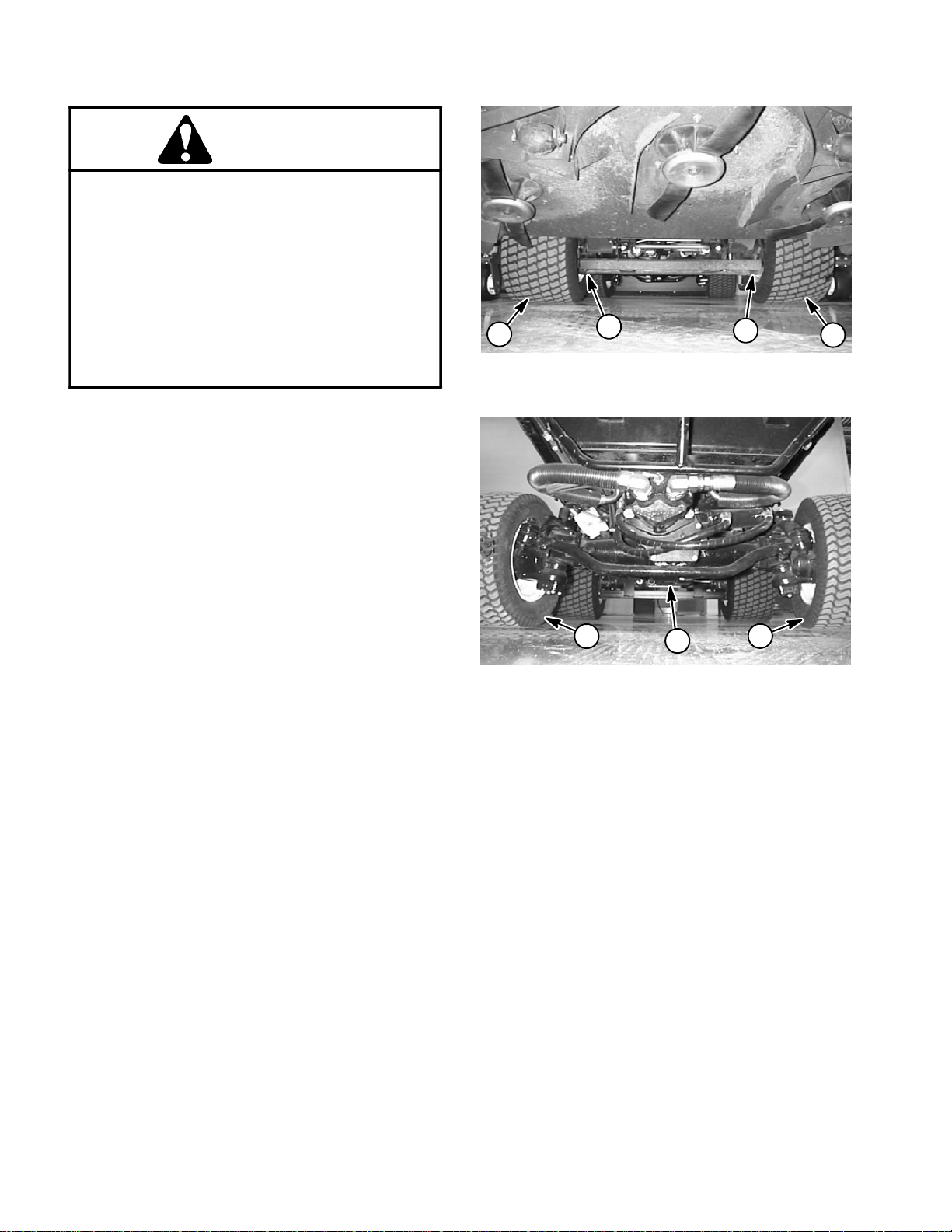
Jacking the Front End (Fig. 1)
1. Set parking brake and chock both rear tires to prevent the machine from moving.
2. Positionjack securelyunder the frame, just to the inside of the front tire. Jack front wheel off the ground.
2
1. Frame jacking point 2. Front tire
1
Figure 1
1
2
3. Once the machine is raised, position jack stand under the frame as close to the wheel as possible to support the machine.
Jacking the Rear End (Fig. 2)
1. Place jack securely under the center of rear axle.
2. Chock both front tires. Jack rear of machine off the
ground.
3. Once the machine is raised, use jack stands under
the axle to support the machine.
2
1. Rear axle jacking point 2. Rear tire
1
Figure 2
2
Safety
Page 1 -- 4
Groundsmaster 4000--D
Page 9

Safety and Instruction Decals
Numerous safety and instruction decals are affixed to
theGroundsmaster4000--D.If anydecalbecomes illegible or damaged, install a new decal. Decal part numbers are listed in your Parts Catalog.
Safety
Groundsmaster 4000--D
Page 1 -- 5
Safety
Page 10

This page is intentionally blank.
Safety
Page 1 -- 6
Groundsmaster 4000--D
Page 11

Product Records and Maintenance
Table of Contents
PRODUCT RECORDS 1.........................
MAINTENANCE 1..............................
EQUIVALENTS AND CONVERSIONS 2...........
Decimal and Millimeter Equivalents 2............
U.S. to Metric Conversions 2...................
TORQUE SPECIFICATIONS 3...................
Fastener Identification 3.......................
Using a Torque Wrench with an Offset Wrench 3..
Standard Torque for Dry, Zinc Plated and
Steel Fasteners (Inch Series) 4...............
Standard Torque for Dry, Zinc Plated and
Steel Fasteners (Metric) 5....................
Other Torque Specifications 6..................
Conversion Factors 6.........................
Chapter 2
Product Records
and Maintenance
Product Records
Insert Operator’s Manuals and Parts Catalogs for your
Groundsmaster at the end of this chapter. Additionally,
if any optional equipment or accessories have been
installed to your machine, insert the Installation Instructions, Operator’s Manuals and Parts Catalogs for those
options at the end of this chapter.
Maintenance
Maintenanceprocedures and recommended service intervalsforyourGroundsmasterarecoveredin theOperator’sManual.Refertothatpublicationwhenperforming
regular equipment maintenance.
Groundsmaster 4000--D Page 2 -- 1 Product Records and Maintenance
Rev. A
Page 12
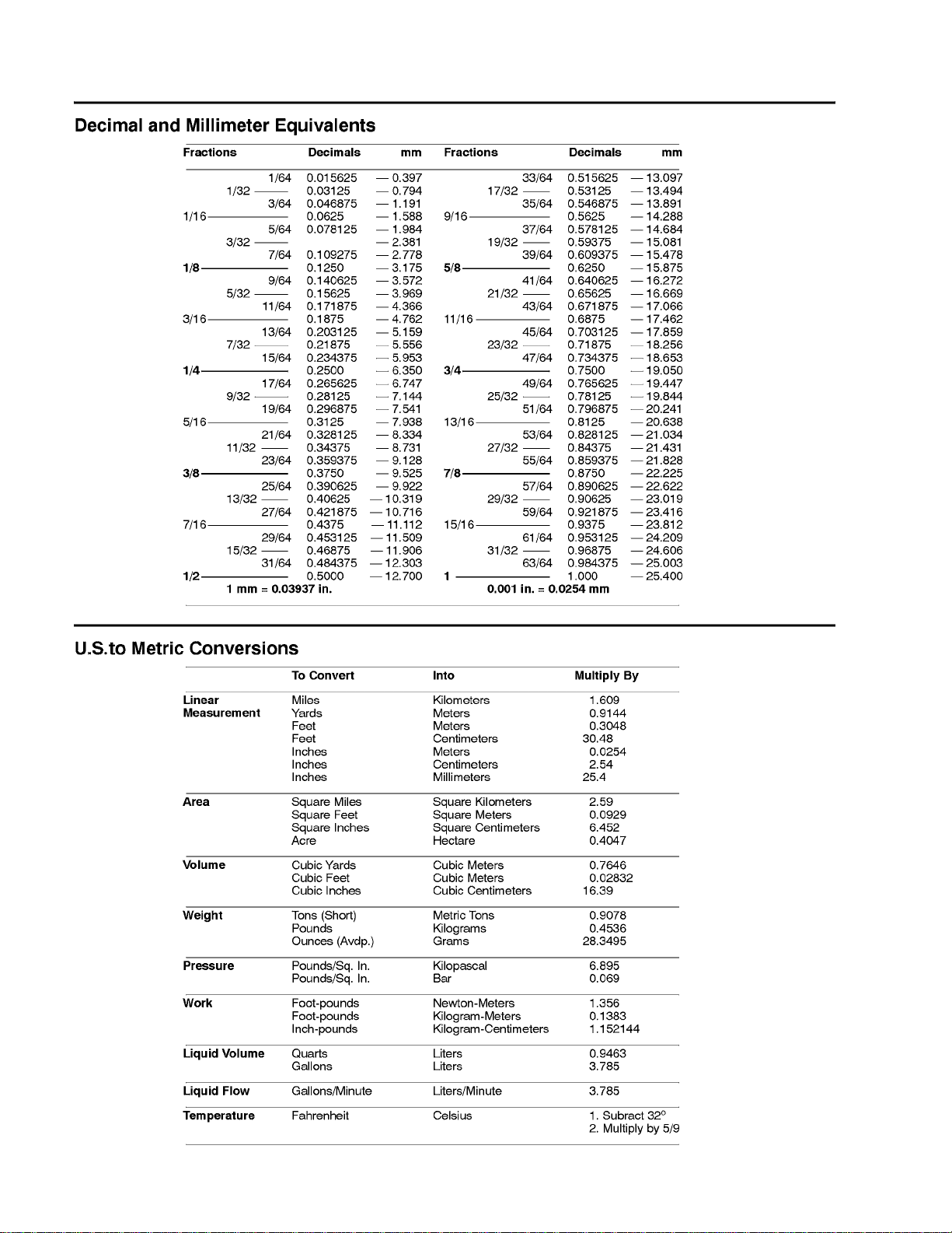
Equivalents and Conversions
0.09375
Groundsmaster 4000--DPage 2 -- 2Product Records and Maintenance
Page 13
Torque Specifications
Recommended fastener torque values are listed in the
following tables. For criticalapplications,as determined
byToro,eitherthe recommended torque or a torquethat
is unique to the application is clearly identified and specified in this Service Manual.
These Torque Specifications for the installation and
tightening of fasteners shall apply to all fasteners which
do not have a specific requirement identified in this Service Manual. The following factors shall be considered
when applying torque: cleanliness of the fastener, use
of a thread sealant (e.g. Loctite), degree of lubrication
on the fastener,presence of a prevailing torque feature
(e.g. Nylock nut), hardness of the surface underneath
thefastener’sheador similar conditionwhichaffectsthe
installation.
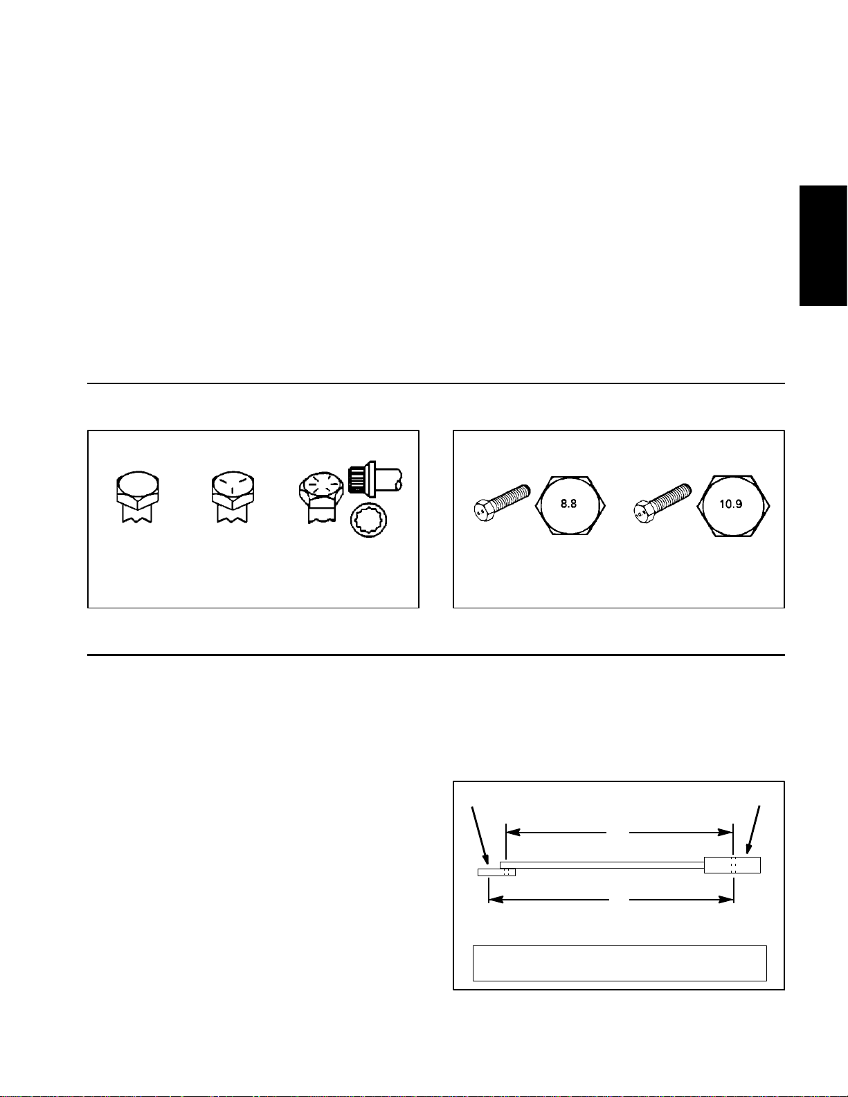
Fastener Identification
Asnoted inthefollowingtables, torquevaluesshould be
reduced by 25% for lubricated fasteners to achieve
the similar stress as a dry fastener. Torque values may
also have to be reduced when the fastener is threaded
into aluminum or brass. The specific torque value
should be determined based on the aluminum or brass
material strength, fastener size, length of thread engagement, etc.
The standard method of verifying torque shall be performed by marking a line on the fastener (head or nut)
and mating part, then back off fastener 1/4 of a turn.
Measurethetorquerequiredto tighten the fastener until
thelinesmatchup.
Product Records
and Maintenance
Grade 1 Grade 5 Grade 8
Inch Series Bolts and Screws
Figure 1
Using a Torque Wrench with an Offset Wrench
Useof anoffsetwrench(e.g.crowfoot wrench)willaffect
torquewrench calibration due to the effective change of
torque wrench length.When using atorque wrench with
an offset wrench, multiply the listed torque recommendation by the calculated torque conversion factor (Fig.
3) to determine proper tightening torque. Tightening
torque when using a torque wrench with an offset
wrench will be lower than the listed torque recommendation.
Example: The measured effective length of the torque
wrench (distance from the center of the handle to the
center of the square drive) is 18”.
Themeasuredeffectivelengthofthe torquewrenchwith
the offset wrench installed (distance from the center of
the handle to the center of the offset wrench) is 19”.
Class 8.8 Class 10.9
Metric Bolts and Screws
Figure 2
If the listed torque recommendation for a fastener is
from 76 to 94 ft--lb, the proper torque when using this
torque wrench with an offset wrench would be from 72
to 89 ft--lb.
(effective length of
torque wrench)
A
B
(effective length of torque
wrench + offset wrench)
TORQUE CONVERSION FACTOR = A / B
T orque wrenchOffset wrench
The calculated t orque conversion factor for this torque
wrenchwith this offset wrench would be 18 / 19= 0.947.
Groundsmaster 4000--D Page 2 -- 3 Product Records and Maintenance
Rev. A
Figure 3
Page 14
Standard Torque for Dry, Zinc Plated and Steel Fasteners (Inch Series)
Thread Size
# 6 -- 32 UNC
# 6 -- 40 UNF
# 8 -- 32 UNC
# 8 -- 36 UNF
#10--24UNC
#10--32UNF
1/4 -- 20 UNC 48 + 7 53 + 7 599 + 79 100 + 10 1130+ 113 140 + 15 1582+ 169
1/4 -- 28 UNF 53 + 7 65 + 10 734 + 113 115 + 12 1299 + 136 160 + 17 1808 + 192
5/16 -- 18 UNC 115 + 15 105 + 15 1186+ 169 200 + 25 2260 + 282 300 + 30 3390 + 339
5/16 -- 24 UNF 138 + 17 128 + 17 1446 + 192 225 + 25 2542 + 282 325 + 33 3672+ 373
3/8 -- 16 UNC 16 + 2 16 + 2 22 + 3 30 + 3 41 + 4 43 + 5 58 + 7
Grade 1, 5 &
8withThin
Height Nuts
in--lb in--lb N--cm in--lb N--cm in--lb N--cm
10 + 2 13 + 2 147 + 23
13 + 2 25 + 5 282 + 56
18 + 2 30 + 5 339 + 56
ft--lb ft--lb N--m ft--lb N--m ft--lb N--m
SAE Grade 1 Bolts, Screws, Studs &
Sems with Regular Height Nuts
(SAE J995 Grade 2 or Stronger Nuts)
SAE Grade 5 Bolts, Screws, Studs &
Sems with Regular Height Nuts
(SAE J995 Grade 2 or Stronger Nuts)
15 + 2 169 + 23 23 + 3 262 + 34
17 + 2 192 + 23 25 + 3 282 + 34
29 + 3 328 + 34 41 + 5 463 + 56
31 + 4 350 + 45 43 + 5 486 + 56
42 + 5 475 + 56 60 + 6 678 + 68
48 + 5 542 + 56 68 + 7 768 + 79
SAE Grade 8 Bolts, Screws, Studs &
Sems with Regular Height Nuts
(SAE J995 Grade 5 or Stronger Nuts)
3/8 -- 24 UNF 17 + 2 18 + 2 24 + 3 35 + 4 47 + 5 50 + 6 68 + 8
7/16 -- 14 UNC 27 + 3 27 + 3 37 + 4 50 + 5 68 + 7 70 + 7 95 + 9
7/16 -- 20 UNF 29 + 3 29 + 3 39 + 4 55 + 6 75 + 8 77 + 8 104 + 11
1/2 -- 13 UNC 30 + 3 48 + 7 65 + 9 75 + 8 102 + 11 105 + 11 142 + 15
1/2 -- 20 UNF 32 + 4 53 + 7 72 + 9 85 + 9 115 + 12 120 + 12 163 + 16
5/8 -- 11 UNC 65 + 10 88 + 12 119 + 16 150 + 15 203 + 20 210 + 21 285 + 28
5/8 -- 18 UNF 75 + 10 95 + 15 129 + 20 170 + 18 230 + 24 240 + 24 325 + 33
3/4 -- 10 UNC 93 + 12 140 + 20 190 + 27 265 + 27 359 + 37 375 + 38 508 + 52
3/4 -- 16 UNF 115 + 15 165 + 25 224 + 34 300 + 30 407 + 41 420 + 43 569 + 58
7/8 -- 9 UNC 140 + 20 225+ 25 305 + 34 430 + 45 583 + 61 600 + 60 813 + 81
7/8 -- 14 UNF 155 + 25 260 + 30 353 + 41 475 + 48 644 + 65 667 + 66 904 + 89
NOTE: Reduce torque values listed in the table above
by 25% for lubricated fasteners. Lubricated fasteners
are defined as threads coated with a lubricant such as
engine oil or thread sealant such as Loctite.
NOTE: The nominal torque values listed above for
Grade 5 and 8 fasteners are based on 75% of the minimumproof load specified in SAE J429. The tolerance is
approximately +
10% of the nominal torque value. Thin
height nuts include jam nuts.
NOTE: Torque values may have to be reduced when
installing fasteners into threaded aluminum or brass.
The specific torque value should be determined based
on the fastener size, the aluminum or base material
strength, length of thread engagement, etc.
Groundsmaster 4000--DPage 2 -- 4Product Records and Maintenance
Page 15
Standard Torque for Dry, Zinc Plated and Steel Fasteners (Metric Series)
Class 8.8 Bolts, Screws and Studs with
Thread Size Regular Height Nuts
(Class 8 or Stronger Nuts)
M5 X 0.8 57 + 6in--lb 644 + 68 N--cm 78 + 8in--lb 881 + 90 N--cm
M6 X 1.0 96 + 10 in--lb 1085 + 113 N- -cm 133 + 14 in--lb 1503 + 158 N--cm
M8 X 1.25 19 + 2ft--lb 26 + 3N--m 28 + 3ft--lb 38 + 4N--m
M10 X 1.5 38 + 4ft--lb 52 + 5N--m 54 + 6ft--lb 73 + 8N--m
M12 X 1.75 66 + 7ft--lb 90 + 10 N--m 93 + 10 ft--lb 126 + 14 N--m
M16 X 2.0 166+ 17 ft--lb 225 + 23 N--m 229 + 23 ft--lb 310 + 31 N--m
M20 X 2.5 325 + 33 ft--lb 440 + 45 N--m 450 + 46 ft--lb 610 + 62 N--m
NOTE: Reduce torque values listed in the table above
by 25% for lubricated fasteners. Lubricated fasteners
are defined as threads coated with a lubricant such as
engine oil or thread sealant such as Loctite.
NOTE: Torque values may have to be reduced when
installing fasteners into threaded aluminum or brass.
The specific torque value should be determined based
on the fastener size, the aluminum or base material
strength, length of thread engagement, etc.
NOTE: The nominal torque values listed above are
based on 75% of the minimum proof load specified in
SAEJ1199.Thetoleranceisapproximately+
nominal torque value.
Class 10.9 Bolts, Screws and Studs with
Regular Height Nuts
(Class 10 or Stronger Nuts)
10%ofthe
Product Records
and Maintenance
Groundsmaster 4000--D Page 2 -- 5 Product Records and Maintenance
Page 16
Other Torque Specifications
*
SAE Grade 8 Steel Set Screws
Recommended Torque
Thread Size
Square Head Hex Socket
1/4 -- 20 UNC 140 + 20 in--lb 73 + 12 in--lb
5/16 -- 18 UNC 215 + 35 in--lb 145 + 20 in--lb
3/8 -- 16 UNC 35 + 10 ft--lb 18 + 3ft--lb
1/2 -- 13 UNC 75 + 15 ft--lb 50 + 10 ft--lb
Thread Cutting Screws
(Zinc Plated Steel)
Type 1, Type 23 or Type F
Thread Size Baseline Torque*
No. 6 -- 32 UNC 20 + 5in--lb
Wheel Bolts and Lug Nuts
Thread Size
7/16 -- 20 UNF
Grade 5
1/2 -- 20 UNF
Grade 5
M12 X 1.25
Class 8.8
M12 X 1.5
Class 8.8
** For steel wheels and non--lubricated fasteners.
Thread Cutting Screws
(Zinc Plated Steel)
Thread
Size
No. 6 18 20 20 + 5in--lb
Threads per Inch
Type A Type B
Recommended Torque**
65 + 10 ft--lb 88 + 14N--m
80 + 10 ft--lb 108 + 14 N--m
80 + 10 ft--lb 108 + 14 N--m
80 + 10 ft--lb 108 + 14 N--m
Baseline Torque
No. 8 -- 32 UNC 30 + 5in--lb
No. 10 -- 24 UNC 38 + 7in--lb
1/4 -- 20 UNC 85 + 15 in--lb
5/16 -- 18 UNC 110 + 20 in--lb
3/8 -- 16 UNC 200 + 100 in--lb
Conversion Factors
in--lb X 11.2985 = N--cm N--cm X 0.08851 = in--lb
ft--lb X 1.3558 = N--m N--m X 0.7376 = ft--lb
No. 8 15 18 30 + 5in--lb
No. 10 12 16 38 + 7in--lb
No. 12 11 14 85 + 15 in--lb
*Holesize,materialstrength,materialthicknessandfinish must be considered when determining specific
torquevalues. Alltorquevalues arebasedonnon--lubricated fasteners.
Groundsmaster 4000--DPage 2 -- 6Product Records and Maintenance
Page 17

Table of Contents
GENERAL INFORMATION 2.....................
Operator’s Manual 2..........................
Stopping the Engine 2.........................
SPECIFICATIONS 3.............................
SERVICE AND REPAIRS 4......................
Air Filter System 4............................
Exhaust System 6............................
Fuel System 8................................
Check Fuel Lines and Connections 9...........
Empty and Clean Fuel Tank 9.................
Fuel Tank Removal 9........................
Fuel Tank Installation 9.......................
Radiator 10..................................
Engine 12....................................
Engine Removal 12..........................
Engine Installation 14........................
Spring Coupler 16.............................
KUBOTA WORKSHOP MANUAL, DIESEL ENGINE,
V2403--M--T--E3B SERIES
Chapter 3
Kubota Diesel Engine
Kubota
Diesel Engine
Groundsmaster 4000--D Page 3 -- 1 Kubota Diesel Engine
Page 18

General Information
ThisChapter gives informationaboutspecificationsand
repair of the diesel engine used in the Groundsmaster
4000--D.
Generalmaintenance procedures are described inyour
Operator’sManual.Informationonenginetroubleshooting,testing, disassembly and reassemblyis identifiedin
the Kubota Workshop Manual, Diesel Engine,
V2403--M--T--E3Bthat is included at the endofthissection.
Most repairs and adjustments require tools which are
commonly available in many service shops. Special
Operator’s Manual
The Operator’s Manual provides information regarding
the operation, general maintenance and maintenance
intervalsfor yourGroundsmastermachine.Refer tothat
publicationfor additional informationwhenservicingthe
machine.
Stopping the Engine
tools are described in the Kubota Workshop Manual,
DieselEngine,V2403--M--T--E3B.Theuseofsomespecialized test equipment is explained. However,the cost
of the test equipment and the specialized nature of
somerepairsmaydictatethattheworkbedoneatanengine repair facility.
Service and repair parts for Kubota engines are supplied through your Authorized Toro Distributor. If no
partslistisavailable,bepreparedtoprovideyourdistributor with the Toro model and serial number.
IMPORTANT: Before stopping the engine after
mowing or full load operation, cool the turbo-charger by allowing the engine to run at low idle speed
for five (5) minutes. Failure to do so may lead to turbo-charger trouble.
Groundsmaster 4000--DPage 3 -- 2Kubota Diesel Engine
Page 19

Specifications
Item Description
Make / Designation Kubota Model V2403--M--T--E3B: 4--Cycle, 4 Cylinder,
Water Cooled, Turbocharged, Diesel Engine
Bore 3.43” (87.0 mm)
Stroke 4.031” (102.4 mm)
Total Displacement 148.5 in3(2434 cc)
Firing Order 1 (closest to gear case end) -- 3 -- 4 (closest to flywheel end) -- 2
Combustion Chamber Spherical Type (E--TVCS)
Compression Ratio 23.0:1
Direction of Rotation Counterclockwise (viewed from flywheel)
Fuel Diesel or Biodiesel (up to B20) Fuel with Low or Ultra Low
Sulfur Content
Fuel Capacity 19.0 U.S. Gallons (72 Liters)
Fuel Injection Pump Denso PFR 4M Type Mini Pump
Injection Nozzle Denso OPD Mini Nozzle
Kubota
Diesel Engine
Governor Centrifugal Mechanical
Low Idle (no load) 1425 + 50 RPM
High Idle (no load) 2870 + 50/--120 RPM
Engine Oil API CH--4, CI--4 or higher
Engine Oil Viscosity See Operator’s Manual
Crankcase Oil Capacity 10.0 U.S. Quarts (9.5 Liters) with Filter
Oil Pump Trochoid Type
Coolant Capacity 13 U.S. Quarts (12.3 Liters)
Starter 12 VDC, 2.0 kW
Alternator/Regulator 12 VDC
Standard Alternator 40 amp
Optional Alternator 90 amp
Engine Dry Weight 419 U.S. Pounds (190 Kg)
Groundsmaster 4000--D Page 3 -- 3 Kubota Diesel Engine
Page 20
Service and Repairs
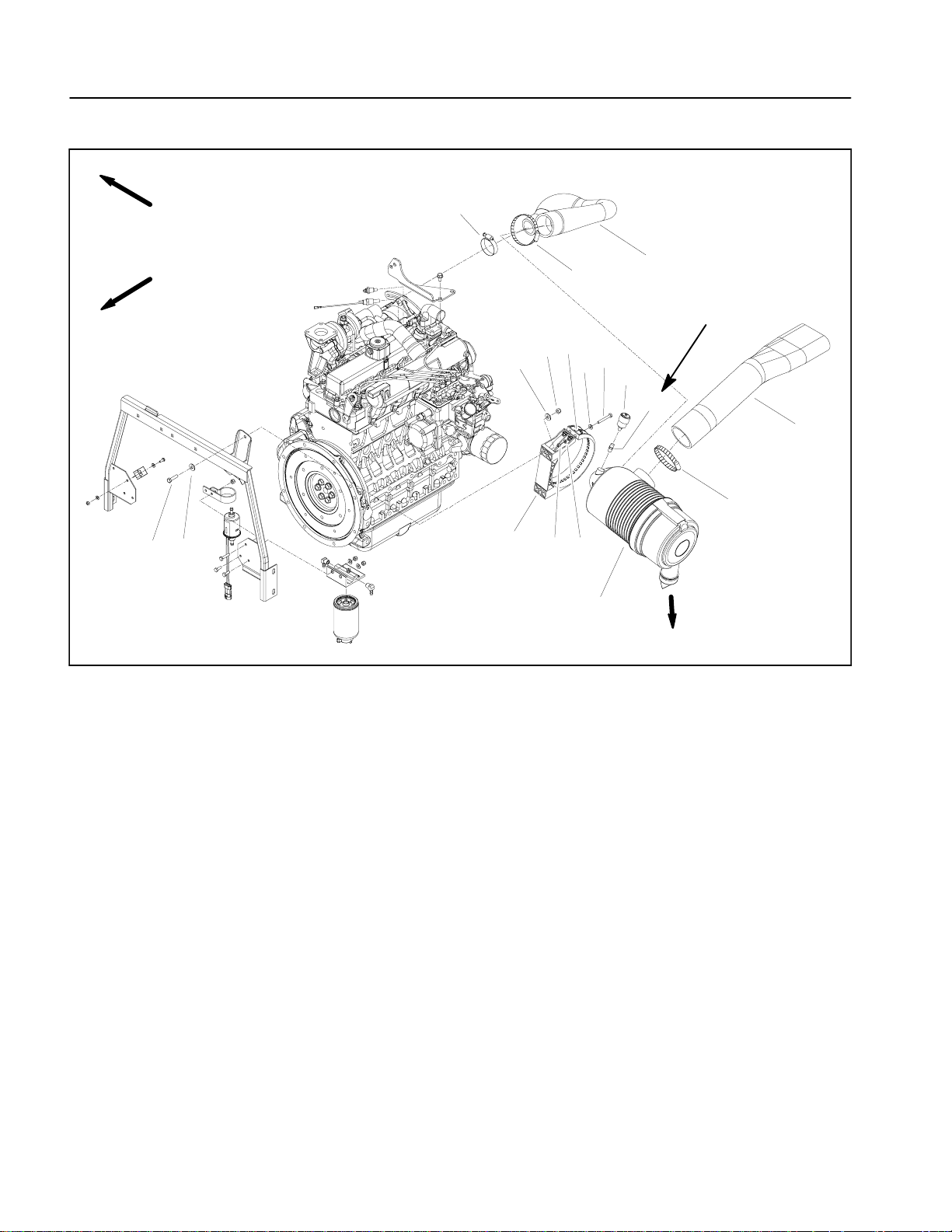
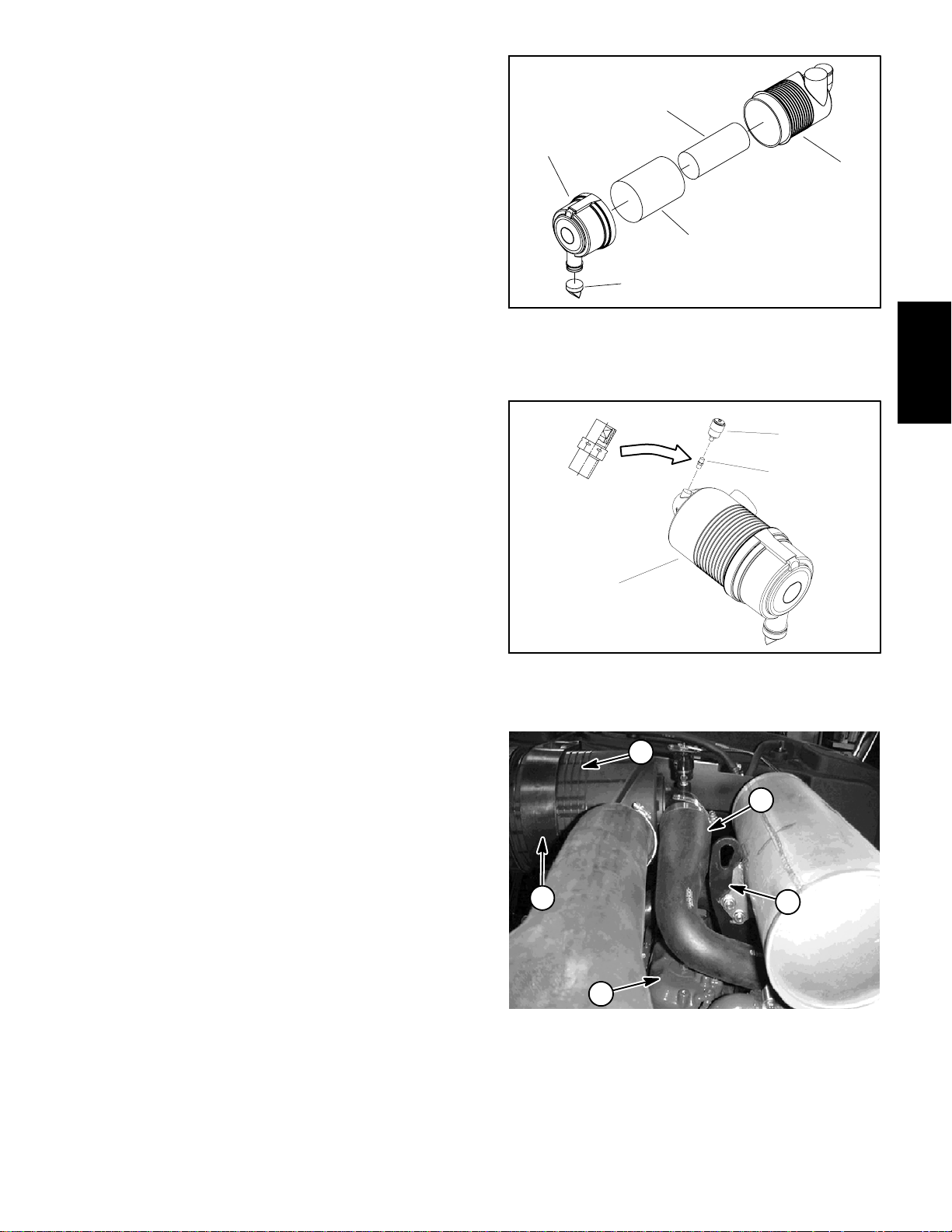
Air Filter System
RIGHT
7
FRONT
10
11
1. Air cleaner hose
2. Hose clamp
3. Air cleaner assembly
4. Indicator
5. Air cleaner strap
6. Lock nut (2 used)
Figure 1
7. Hose clamp
8. Air cleaner hose
9. Hose clamp
10. Cap screw (2 used)
11. Flat washer (4 used)
12. Spring (2 used)
1
9
12 to 15 in--lb
(1.4 to 1.6 N--m)
12
6
11
5
16
14
13
4
15
17
3
13. Flat washer (2 used)
14. Cap screw (2 used)
15. Adapter
16. Lock nut (2 used)
17. Flat washer (2 used)
8
2
VACUATOR
DIRECTION
Groundsmaster 4000--DPage 3 -- 4Kubota Diesel Engine
Page 21
Removal (Fig. 1)
1. Park machine on a level surface, lower cutting
decks, stop engine, apply parking brake and remove
key from the ignition switch.
2. Raise and support hood.
3. Remove air cleaner components as needed using
Figure 1 as a guide.
Installation (Fig. 1)
IMPORTANT: Any leaks in the air filter system will
causeserious engine damage.Make surethat allair
cleaner components are in good condition and are
properly secured during assembly.
1. Assemble air cleaner system using Figure 1 as a
guide.
A. If service indicator (item 8) and adapter (item 9)
wereremovedfromaircleanerhousing,applythread
sealant to adapter threads before installing adapter
and indicator to housing. Install adapter so that
groovesinadapter hexandadapterfilter elementare
installed toward serviceindicator (Fig. 3). Torque indicator from 12 to 15 in--lb (1.4 to 1.6 N--m).
4
5
1. Air cleaner housing
2. Safety filter element
3. Air filter element
2
1
3
Figure 2
4. Air cleaner cover
5. Vacuator valve
Kubota
Diesel Engine
2
3
2. When installing air cleaner hose (8) between air
cleaner and turbo--charger (Fig. 4):
A. Make sure that hose does not contact engine
valve cover. To ensure clearance, move and/or rotate air cleaner body in air cleaner strap.
B. Position hose to allow maximum clearance between air cleaner hose and muffler bracket.
3. Lower and secure hood.
1
1. Air cleaner assembly
2. Service indicator
4
3
2
1. Air cleaner hose
2. Engine valve cover
3. Air cleaner strap
Figure 3
3. Adapter
1
5
Figure 4
4. Air cleaner slots
5. Muffler bracket
Groundsmaster 4000--D Page 3 -- 5 Kubota Diesel Engine
Page 22
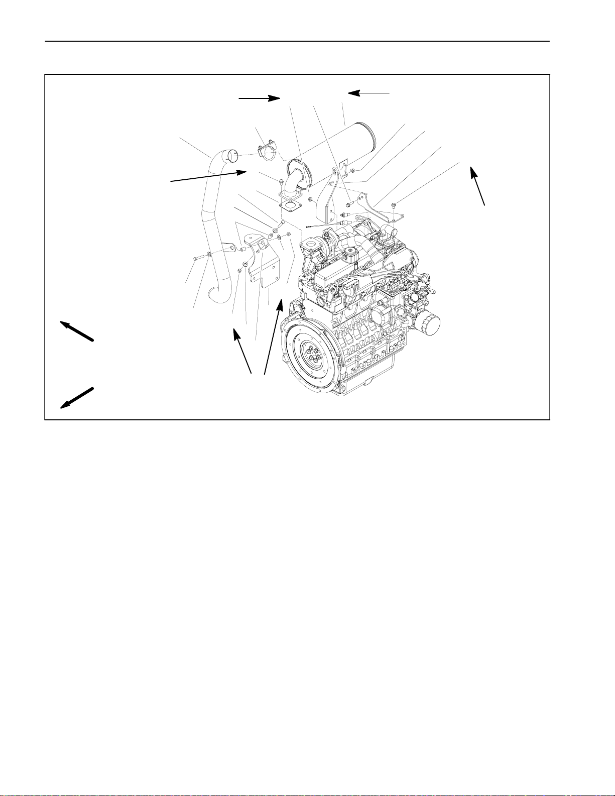
Exhaust System
RIGHT
FRONT
16 to 22 ft--lb
(21to29N--m)
16 to 22 ft--lb
(21to29N--m)
3
7
8
14
4
5
7
8
9
6
13
8
10
16 to 22 ft--lb
(21to29N--m)
11
12
1
16 to 22 ft--lb
(21to29N--m)
11
2
15
16
13 ft--lb
(17.6 N--m)
8
6
1. Muffler
2. Muffler bracket
3. Exhaust pipe
4. Flange head screw (4 used)
5. Exhaust gasket
6. Lock nut (2 used)
Figure 5
7. Cap screw (2 used)
8. Flat washer (4 used)
9. Spacer (2 used)
10. Rubber hanger
11. Flange nut (4 used)
12. Flange head screw (2 used)
13. Engine mount
14. Muffler clamp
15. Exhaust mount
16. Flange head screw (2 used)
Groundsmaster 4000--DPage 3 -- 6Kubota Diesel Engine
Page 23
Removal (Fig. 5)
CAUTION
The muffler and exhaust pipe may be hot. To
avoid possible burns, allow the engine and exhaust system to c ool before working on the muffler.
1. Park machine on a level surface, lower cutting
decks, stop engine, apply parking brake and remove
key from the ignition switch.
2. Raise and support hood.
3. Remove exhaust system components from the engine as necessary using Figure 5 as a guide.
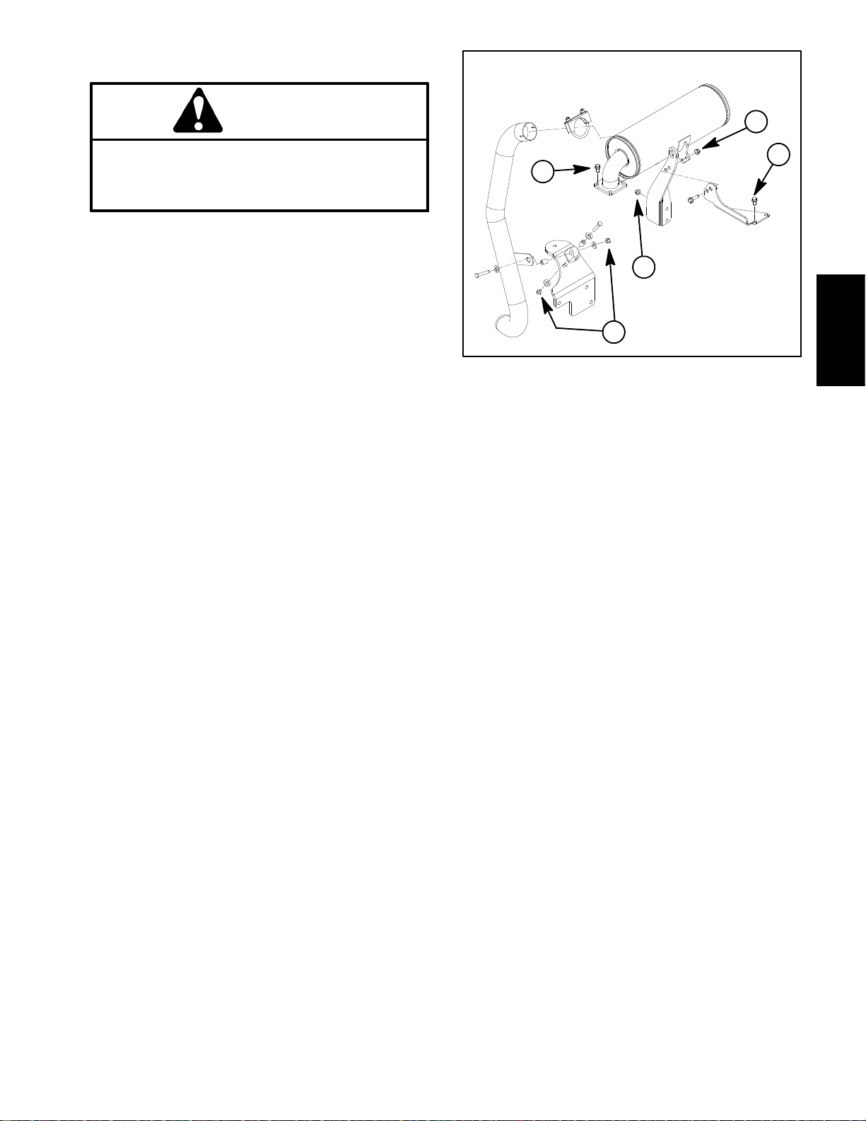
Installation (Fig. 5)
IMPORTANT: If exhaust studs were removed from
engine cylinder head, thoroughly clean threads in
head and apply Loctite #277 (or equivalent) to stud
threads before installing studs into head.
NOTE: Make sure muffler flange and exhaust manifold
sealing surfaces are free of debris or damage that may
prevent a tight seal.
B
E
C
D
A
Kubota
Figure 6
Diesel Engine
1. Install new exhaust gasket if original gasket is damaged or torn.
IMPORTANT: Failure to follow the suggested muffler fastener sequencemay result in prematuremuffler failure.
2. Installexhaust system components to theengineusing Figure 5 as a guide. Hand tighten exhaust system
fastenersand thentorqueinthesequence showninFig.
6 as follows:
A. Torque lock nuts used on rubber hanger cap
screws from 16 to 22 ft--lb (21 to 29 N--m).
B. Torque flange nuts that secure muffler to muffler
bracket from 16 to 22 ft--lb (21 to 29 N--m).
C. Torque flange head screws that secure muffler
flange to engine from 16 to 22 ft--lb (21 to 29 N--m).
D. T orqueflangenuts that securemuffler bracketto
engine from 16 to 22 ft--lb (21 to 29 N--m).
E. Torqueflange screws that secure exhaust mount
to engine to 1 3 f t -- l b ( 1 7 . 6 N -- m ) .
3. Tailpipeshouldhave equalclearancebetweenframe
and engine after installation.
4. Lower and secure hood.
Groundsmaster 4000--D Page 3 -- 7 Kubota Diesel Engine
Rev. A
Page 24
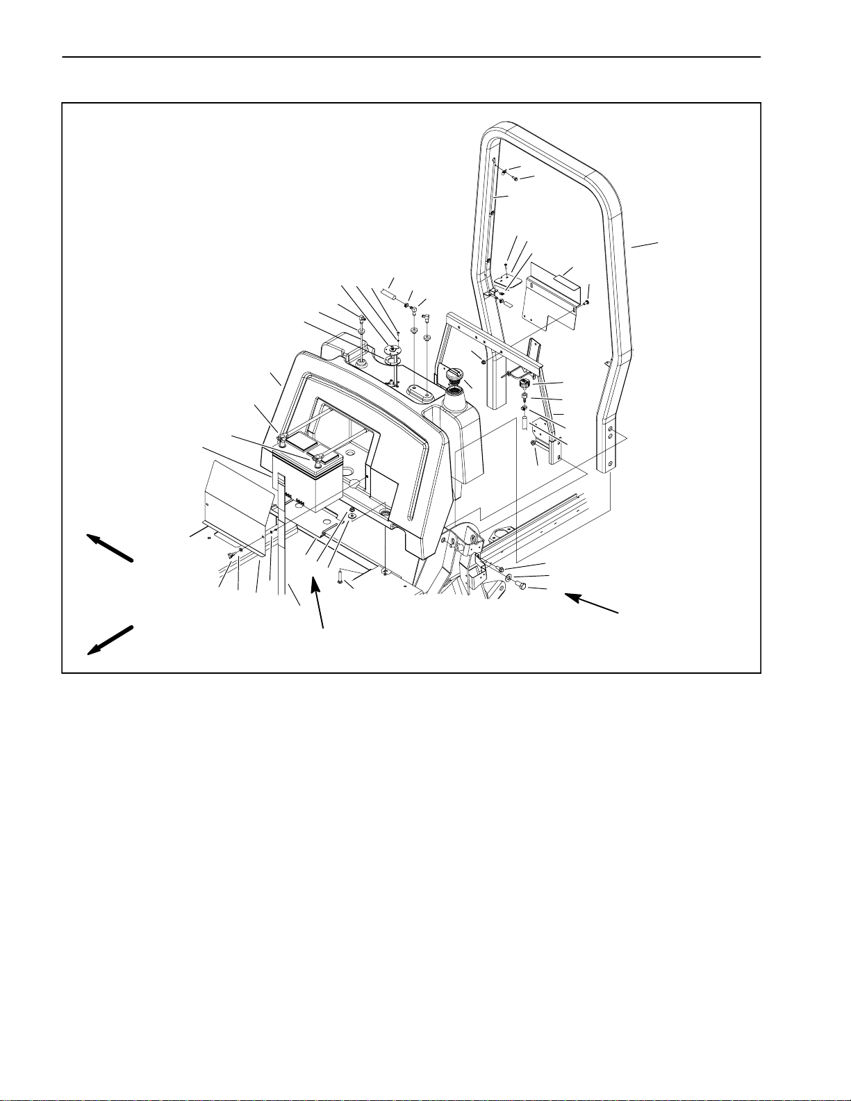
Fuel System
14
20
21
38
39
37
36
24
25
26
27
28
29
30
35
34
2
22
31
41
23
33
1
3
32
4
5
40
6
7
RIGHT
FRONT
1. Fuel tank
2. Fuel tank bracket
3. Air breather
4. Female hose barb
5. Tank support assembly
6. Fuel hose
7. Flange nut (6 used)
8. Cap screw (4 used)
9. Flat washer (4 used)
10. Cap screw (4 used)
11. Carriage screw (2 used)
12. Washer (2 used)
13. Battery strap
14. Battery
18
17
16
15
19
7
12
11
13
60 to 80 in--lb
(7 to 9 N--m)
Figure 7
15. Retaining ring (2 used)
16. Battery cover
17. Flat washer (2 used)
18. Knob (2 used)
19. Battery plate
20. Negative cable
21. Positive cable
22. Carriage screw
23. Gasket
24. Bushing (3 used)
25. Stand pipe
26. Fuel sender
27. Lock washer (5 used)
28. Phillips head screw (5 used)
8
9
10
135 to 165 ft--lb
(183 to 223 N--m)
29. Fuel hose
30. Hose clamp
31. Elbow fitting (2 used)
32. Fuel cap
33. Locking flange nut (2 used)
34. Speed nut
35. Tank cover (2 used)
36. Phillips head screw (4 used)
37. Vent tube
38. Insulated clip (3 used)
39. Washer head screw (3 used)
40. Hose clamp (4 used)
41. ROPS assembly
Groundsmaster 4000--DPage 3 -- 8Kubota Diesel Engine
Page 25
Fuel Tank Installation (Fig. 7)
DANGER
Becausedieselfuel ishighly flammable,use caution when storing or handling it. Do not smoke
while filling the fuel tank. Do not fill fuel tank
while engine is running, hot or when machine is
in an enclosed area. Always fill fuel tank outside
and wipe up any spilled diesel fuel before starting the engine. Store fuel in a clean, safety--approved container and keep cap in place. Use diesel fuel for the engine only; not for any other
purpose.
Check Fuel Lines and Connections
Checkfuel lines and connectionsperiodicallyasrecommendedinthe Operator’sManual.Check lines for deterioration, damage, leaking or loose connections.
Replace hoses, clamps and connections as necessary.
Empty and Clean Fuel Tank
Empty and clean the fuel tank periodically as recommended in the Operator’s Manual. Also, empty and
clean the fuel tank if the fuel system becomes contaminated or if the machine is to be stored for an extended
period.
1. Install fuel tank using Figure 7 as a guide.
A. Torquetwo(2)flange nuts(item7)thatsecure the
fuel tank to the frame from 60 to 80 in--lb (7 to 9
N--m).
2. Install two (2) tank covers to ROPS assembly.
3. Connect fuel hose to the standpipe and venting
hoses to the elbow fittings.
4. Connect electrical wiring to the sending unit.
A. Connect white wire to the center terminal and
black wire to any of the screws that secure the fuel
sender to the fuel tank.
B. Apply skin--over grease to the wire terminal connections.
CAUTION
Connecting battery cables to the wrong battery
post could result in personal injury and/or damage to the electrical system.
Kubota
Diesel Engine
To clean fuel tank, flush tank out with clean diesel fuel.
Make sure tank is free of contaminates and debris.
Fuel Tank Removal (Fig. 7)
1. Park machine on a level surface, lower cutting
decks, stop engine, apply parking brake and remove
key from the ignition switch.
2. Raise and support operator seat and hood.
3. Remove battery cover and strap. Disconnect negative battery cable first and then positive battery cable.
Remove battery from machine.
4. Usea fuel transfer pump toremove fuelfrom the fuel
tank and into a suitable container.
5. Disconnect electrical wiring from the sending unit.
6. Disconnectfuelhosefromthestandpipe andventing
hoses from elbow fittings in top of tank.
7. Remove phillips head screws that secure two (2)
tank covers to ROPS assembly.Remove tank covers.
5. Positionbatteryinmachine.Connectpositivebattery
cable first and then negative battery cable. Install battery strap and cover.
6. Lower seat and hood.
7. Fill fuel tank.
8. Remove fuel tank using Figure 7 as a guide.
Groundsmaster 4000--D Page 3 -- 9 Kubota Diesel Engine
Page 26
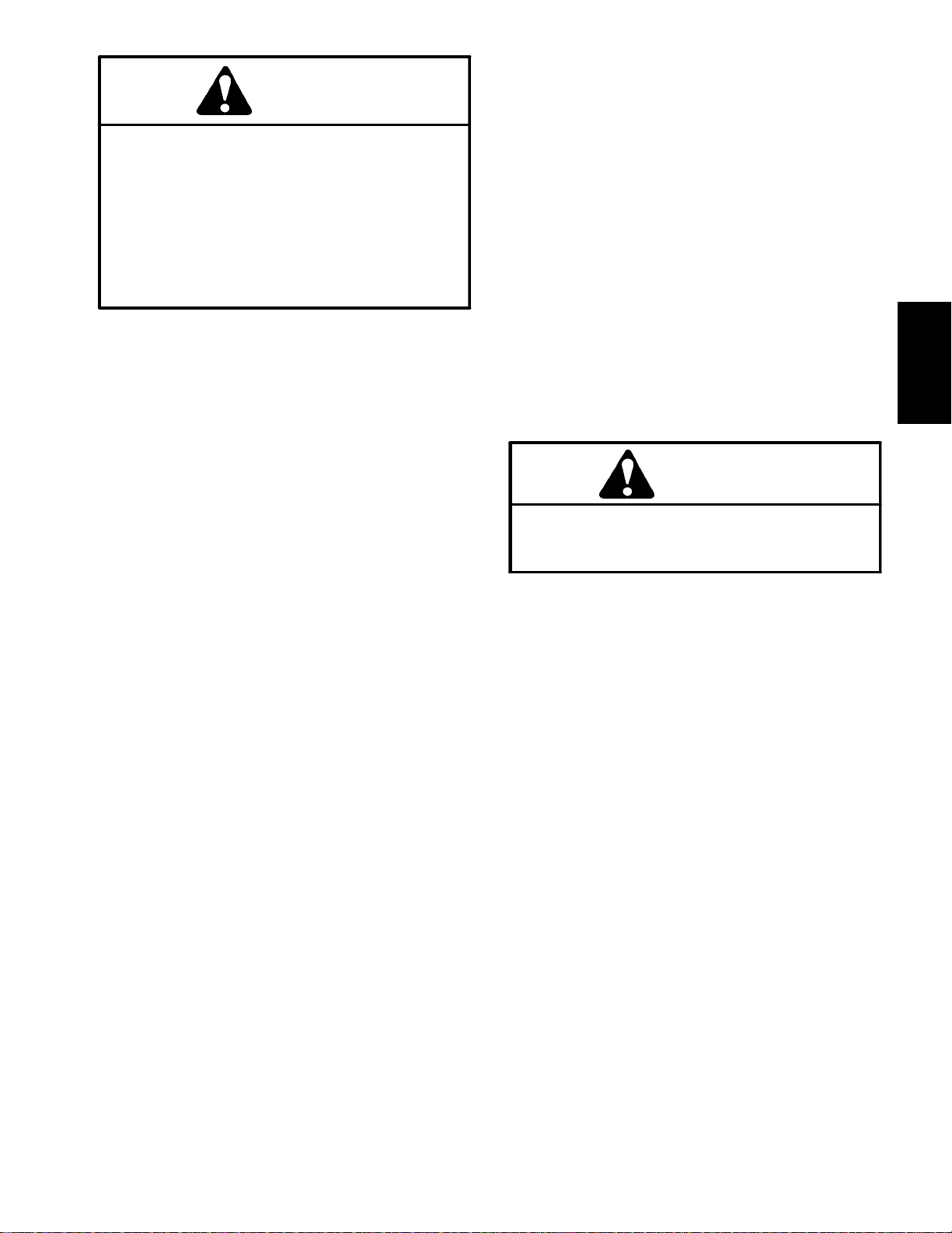
Radiator
61
32
13
RIGHT
FRONT
14
35
34
38
48
20
19
28
22
23
24
25
21
49
25
26
45
54
12
27
7
46
18
16
28
51
53
17
62
1
52
9
50
8
6
41
30
59
4
5
55
37
56
11
29
58
49
10
60
57
42
43
15
41
44
45
47
2
31
33
28
58
3
1. Radiator cap
2. Foam strip (2 used)
3. Foam strip (2 used)
4. Lower radiator hose
5. Upper radiator hose
6. Clamp (4 used)
7. Lower radiator shroud
8. Temperature sender
9. Radiator
10. Hose clamp (3 used)
11.Hose(2used)
12. Screw (4 used)
13. Rubber grommet
14. Flange nut (4 used)
15. Retaining ring (2 used)
16. Knob (2 used)
17. Bulb seal
18. Top radiator support
19. Retaining ring (2 used)
20. Oil cooler bracket
21. Oil cooler
3639
40
Figure 8
22. Carriage screw (2 used)
o
23. 90
hydraulic fitting (2 used)
24. Cap screw (6 used)
25. Lock washer (6 used)
26. Oil cooler mount plate (2 used)
27. Upper radiator shroud
28. Flange nut (10 used)
29. Foam plug (2 used)
30. Lock nut (6 used)
31. Foam strip
32. Base bracket
33. Flange head screw (6 used)
34. Bulb seal (2 used)
35. Grommet (2 used)
36. Cover
37. Flange head screw (4 used)
38. Plate (2 used)
39. Flat washer (2 used)
40. Knob (2 used)
41. Cap screw (6 used)
42. Cable tie
43. Coolant reservoir
44. Tank bracket
45. Flat washer (10 used)
46. Foam pad
47. Cap screw (7 used)
48. Foam seal
49. Cap screw (3 used)
50. LH radiator support
51. RH radiator support
52. Flange nut (6 used)
53. Cap screw (6 used)
54. Fan motor bracket
55. Grommet (2 used)
56. Grommet
57. Harness clip
58. R--clamp (2 used)
59. Foam pad
60. Reservoir cap
61. Air cleaner hose
62. Plug
Groundsmaster 4000--DPage 3 -- 10Kubota Diesel Engine
Page 27
Removal (Fig. 8)
Installation (Fig. 8)
1. Park machine on a level surface, lower cutting
decks, stop engine, apply parking brake and remove
key from the ignition switch.
2. Open and support hood.
CAUTION
Do not open radiator cap or drain coolant if the
radiator or engine is hot. Pressurized, hot coolant can escape and cause burns.
Ethylene--glycol antifreeze is poisonous. Dispose of coolant properly or store it in a properly
labeled container away from children and pets.
3. Drain radiator into a suitable container using the radiator drain. The radiator drain hose is located near the
engine oil filter.
4. Disconnectupper and lower radiator hoses fromthe
radiator.
5. Remove air cleaner hose (item 61).
6. Disconnect reservoir hose from the vent tube near
the radiator cap.
1. Remove all plugs placed during the removal procedure.
2. Carefully position radiator to the support frame. Secure radiator to the support frame with cap screws and
flange nuts.
3. Positionlower radiatorshroudandfan motor bracket
assembly to the radiator.
4. Secure fan motor bracket to radiator with six (6)
flange head screws and flange nuts.
5. Position upper radiator shroud to lower radiator
shroud to radiator. Secure shrouds with removed fasteners.
6. Attach radiator shroud assembly to the radiator with
cap screws and flat washers. Make sure that clearance
between shroud and cooling fan is at least 0.180” (4.6
mm) at all points.
7. Connectreservoir hose to the vent tube near the radiator cap.
8. Connectupperandlowerradiatorhosesto theradiator.
9. Reinstall air cleaner hose (item 61).
Kubota
Diesel Engine
7. Detach upper radiator shroud from the radiator and
lower radiator shroud. Remove upper shroud from machine.
8. Removefasteners that secure lower radiatorshroud
to radiator.
9. Remove six (6) flange head screws and flange nuts
that secure fan motor bracket to radiator.
10.Position lowerradiatorshroudand fan motorbracket
assembly away from radiator.
11.Removecapscrewsand flangenutssecuringthe radiator to the support frame. Carefully pull radiator from
the machine.
12.Plugallradiatororhoseopeningstopreventcontamination.
10.Make sure radiator drain is closed. Fill radiator with
coolant.
11.Close and secure hood.
Groundsmaster 4000--D Page 3 -- 11 Kubota Diesel Engine
Page 28
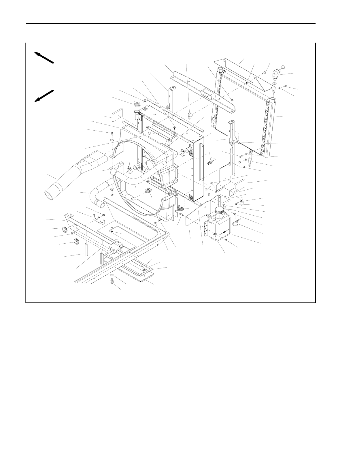
Engine
21
23
22
RIGHT
FRONT
24
25
26
14
13
27
12
11
1
2
3
4
5
6
7
9
8
13
20
15
13
16
18
19
28 to 32 ft--lb
(38to43N--m)
1. Engine
2. Cap screw (4 used)
3. LH engine mount
4. Lock washer
5. Cap screw
6. Lock washer (5 used)
7. Cap screw (5 used)
8. Engine support (4 used)
9. Flange nut (12 used)
17
28 to 32 ft--lb
(38to43N--m)
10. Rebound washer (4 used)
11. Cap screw (8 used)
12. Spring coupler
13. Washer (14 used)
14. Cap screw (6 used)
15. Flywheel plate
16. Cap screw (4 used)
17. Cap screw (2 used)
18. Lock washer (2 used)
Engine Removal (Fig. 9)
1. Park machine on a level surface, lower cutting
decks, stop engine, apply parking brake and remove
key from the ignition switch.
10
9
Loctite #242
29 to 33 ft--lb
(40to44N--m)
Figure 9
19. LH engine mount
20. Cap screw (4 used)
21. RH engine mount
22. Cap screw (PTO manifold)
23. Lock washer
24. Ground cable
25. Cap screw
26. Lock washer
27. RH engine mount
2. Remove battery cover and strap. Disconnect negative battery cable first and then positive battery cable.
Remove battery from machine.
3. Open and support hood.
Groundsmaster 4000--DPage 3 -- 12Kubota Diesel Engine
Page 29
CAUTION
Do not open radiator cap or drain coolant if the
radiator or engine is hot. Pressurized, hot coolant can escape and cause burns.
Ethylene--glycol antifreeze is poisonous. Dispose of coolant properly or store it in a properly
labeled container away from children and pets.
2
1
4. Drain coolant from the radiator into a suitable container (see Radiator Removal in this section). Disconnect upper and lower hoses from the radiator.
CAUTION
The muffler and exhaust pipe may be hot. To
avoid possible burns, allow the exhaust system
to cool before working on or near the muffler.
5. Remove exhaust system from engine (see Exhaust
System Removal in this section).
6. Removeaircleaner system from engine (see Air Filter System Removal in this section).
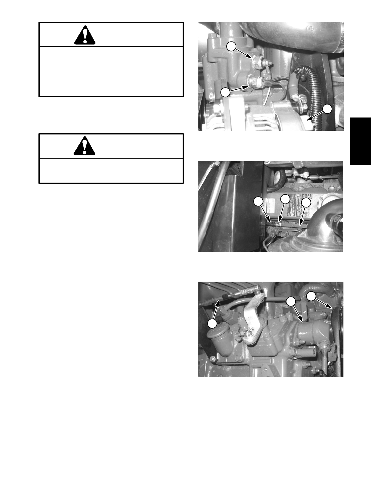
7. Note location of cable ties used to secure wire harness to the machine. Disconnect wires and/or electrical
connections from the following electrical components:
A. The dual temperature switch, temperature sender and alternator (Fig 10).
1. Dual temp switch
2. Temperature sender
1. Glow plug wire
2. Glow plug lead
Figure 10
1
Figure 11
3
3. Alternator
3
3. Cylinder #4 glow plug
2
Kubota
Diesel Engine
B. The glow plugs (Fig. 11).
C. The engine run solenoid (Fig. 12).
1
2
D. Battery,frameandwireharness groundattheengine block.
3
E. The electric starter and low oil pressure switch
(near electric starter).
8. Disconnect fuel line from injection pump.
9. Disconnect throttle cable from the speed control lever by removing the flat washer and lock nut (Fig. 13).
Loosenjam nut andseparate cable from cable support.
Position cable away from engine.
10.Remove fasteners that secure the upper radiator
1. Engine run solenoid
2. Alternator belt
Figure 12
3. Throttle cable
shroud to the lower shroud and radiator (see Radiator
Removal in this section). Position coolant reservoir and
bracket away from the radiator. Remove upper radiator
shroud from machine.
Groundsmaster 4000--D Page 3 -- 13 Kubota Diesel Engine
Page 30
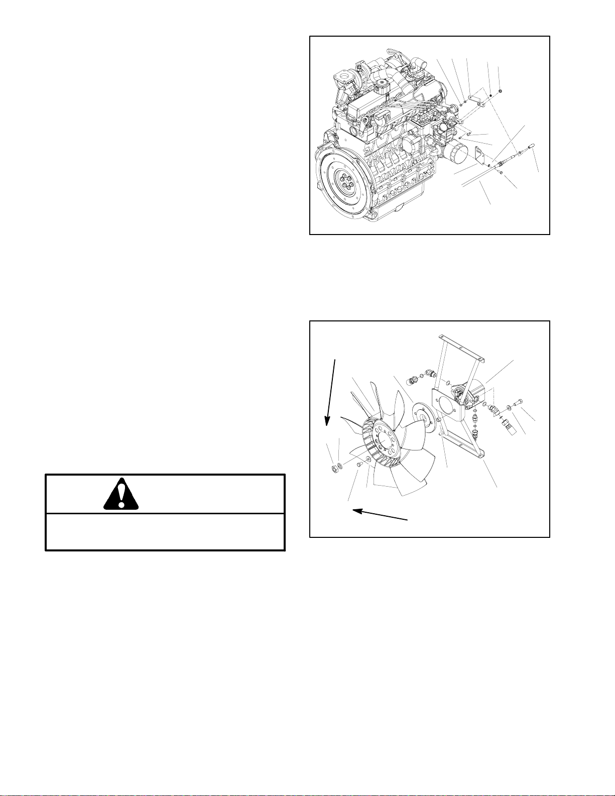
11.Remove fan hub and fan from hydraulic fan motor
(Fig. 14).
A. Removehex nut(item9)and washer (item8)that
secure fan hub and fan assembly to fan motor.
NOTE: The fan motor shaft is tapered.
B. Usesuitablepullertoremove fanhub(with fanat-
tached) from fan motor shaft taking care to not damage fan. Remove fan hub and fan from machine.
1
4
5
8
6
7
3
2
12.Remove transport cylinder assembly from engine
mount (Fig. 15). It is not necessary to remove the hydraulichose from the cylinder.Locate and remove shim
plate(s) from between transport cylinder and engine
mount.
IMPORTANT: The hydraulic pump assembly can remain in machine during engine removal. Toprevent
pump from shifting or falling, make sure to support
pump assembly before mounting fasteners are removed.
13.Support hydraulic pump assembly. Remove fasteners that secure pump assembly to engine (see Pump
Assembly Removal in the Service and Repairs section
of Chapter 4 -- Hydraulic System).
14.Make sure all cable ties securingthewiringharness,
fuellines or hydraulic hoses to the engine are removed.
15.Connect hoist or lift to the lift tabs on engine.
16.Remove flange nuts, rebound washers and cap
screws securing the engine mounts to the engine supports.
1. Lock nut
2. Flat washer
3. Throttle lever
4. Lock nut
5. Flange head screw
6. Cap screw
27 to 33 ft--lb
(37to44N--m)
11
9
8
10
12
Figure 13
7. Flange head screw
8. Spring washer (2 used)
9. Ball joint
10. Cap screw (2 used)
11. Throttle cable
12. Cable support
9
10
11
1
2
3
CAUTION
One person should operate lift or hoist while
another person guides the engine out of the machine.
IMPORTANT: Make sure not to damage the engine,
fuel and hydraulic lines, electrical harness or other
components while removing the engine.
17.Carefully remove engine assembly from the machine.
18.Ifnecessary,removeengine mountsfromthe engine
using Figure 9 as a guide.
Engine Installation (Fig. 9)
1. Ifremoved,installengine mountstothe engineusing
Figure 9 as a guide.
2. Connect hoist or lift to the engine lift tabs.
6
7
1. Fan motor
2. Cap screw (2 used)
3. Flat washer (2 used)
4. Fan motor bracket
5. Lock nut (2 used)
6. Washer (4 used)
5
4
12 to 14 ft--lb
(17to18N--m)
Figure 14
7. Cap screw (4 used)
8. Hex nut
9. Washer
10. Fan hub
11. Fan
Groundsmaster 4000--DPage 3 -- 14Kubota Diesel Engine
Page 31

CAUTION
One person should operate lift or hoist while
another person guides the engine into the machine.
IMPORTANT: Make sure not to damage the engine,
fuel and hydraulic lines, electrical harness or other
parts while installing the engine.
3. Carefully lower engine into the machine.
12.Install aircleanerassembly totheengine (seeAirFilter System Installation in this section).
13.Installexhaustsystemtomachine(seeExhaustSystem Installation in this section).
14.Connect coolant hosestotheradiator.Makesureradiator drain is shut. Fill radiator and reservoir with coolant.
15.Check position of wires, fuel lines, hydraulic hoses
andcables for proper clearance with rotating, high temperature and moving components.
4. Align engine to the engine supports and hydraulic
pumpinputshaft.Secureenginetoenginesupportswith
cap screws, rebound washers and flange nuts.
5. Secure hydraulic pump assembly to engine (see
Pump Assembly Installation in the Service and Repairs
section of Chapter 4 -- Hydraulic System).
6. Thoroughly clean tapered surfaces of fan motor
shaft and fan hub. Position fan hub (with fan attached)
onto motor shaft and secure with washer and hex nut
(Fig.14). Torquenutfrom27to33ft--lb (37 to 44 N--m).
7. Positionupper radiator shroudandcoolantreservoir
withbrackettotheradiator.Secureshroudandreservoir
bracket to the radiator and lower radiator bracket with
removedfasteners (seeRadiatorInstallationin this section).Make sure thatclearancebetweenshroud and fan
is at least 0.180” (4.6 mm) at all points.
8. Connectthrottle cable tothespeedcontrollever with
washer and lock nut (Fig. 13). Secure cable to cable
support. Adjust throttle cable.
9. Connect fuel line to the injection pump.
10.Install transportcylinderassemblyto engine adapter
plate (Fig. 15). Make sure that removed shim(s) are
positioned between transport cylinder and engine
mount.
11.Connect wires and/or electrical connections to the
following electrical components:
A. Thedual temperature switch, temperature sender and alternator (Fig 10).
16.Position battery to machine. Connect positive battery cable first and then negative battery cable. Secure
battery to machine with strap and cover.
17.Check and adjust engine oil as needed.
18.Check and adjust hydraulic oil as needed.
19.Bleed fuel system.
20.Start engine and operate hydraulic controls to properlyfill hydraulic system(see Charge Hydraulic System
in Chapter 4 -- Hydraulic System).
21.Close and secure hood.
13
14
RIGHT
FRONT
9
11
12
10
8
1
4
5
6
7
2
3
Figure 15
1. Carriage screw (2 used)
2. Shim
3. Transport cylinder
4. Lock nut (2 used)
5. Piston
6. Backup ring (2 used)
7. O--ring (2 used)
8. Retaining ring
9. Seal
10. O--ring
11. Fitting
12. O--ring
13. Hydraulic hose
14. Engine mount
Kubota
Diesel Engine
B. The glow plug (Fig. 11).
C. The engine run solenoid (Fig. 12).
D. Battery,frameandwireharness groundtotheen-
gine block.
E. The starter and low oil pressure switch (near
starter).
Groundsmaster 4000--D Page 3 -- 15 Kubota Diesel Engine
Page 32

Spring Coupler
RIGHT
FRONT
21
20
19
18
17
14
15
16
1. Spring coupler
2. Washer (14 used)
3. Cap screw (6 used)
4. Flywheel plate
5. Cap screw (4 used)
6. LH engine mount
7. Cap screw (2 used)
13
12
11
10
9
7
8
8. Carriage screw (2 used)
9. Cylinder shim
10. Transport cylinder
11. Lock nut (2 used)
12. Cylinder piston
13. O--ring (2 used)
14. Backup ring (2 used)
5
6
Figure 16
2
3
4
28 to 32 ft--lb
(38to43N--m)
15. Retaining ring
16. Seal
17. O--ring
18. Hydraulic fitting
19. O--ring
20. Hydraulic hose
21. RH engine mount
1
2
Loctite #242
29 to 33 ft--lb
(40to44N--m)
Groundsmaster 4000--DPage 3 -- 16Kubota Diesel Engine
Page 33

Coupler Removal (Fig. 16)
NOTE: The hydraulic pump assembly needs to be re-
moved from engine before coupler can be removed.
1. Ifengine is in machine,supportenginefrom below to
prevent it from shifting while removing hydraulic pump
assembly (see Piston (Traction) Pump Removal in the
Service and Repairs section of Chapter 4 -- Hydraulic
System), transport cylinder assembly, flywheel plate,
engine mounts and spring coupler.
2. Remove flywheel plate and spring coupler from engine using Figure 16 as a guide.
Coupler Installation (Fig. 16)
1. Position spring coupler to engine flywheel and align
mounting holes. Make sure that coupling hub is away
from engine flywheel (Fig. 17).
2. Apply Loctite #242 (or equivalent) to threads of cap
screws (item 3). Secure coupler to flywheel with six (6)
capscrews and washers. Torquecapscrewsin a crossing pattern from 29 to 33 ft--lb (40 to 44 N--m).
Engine Side Hydraulic
Pump Side
1
2
Figure 17
1. Coupler 2. Engine flywheel
Kubota
Diesel Engine
3. Positionflywheelplate toengineandenginemounts.
Secure flywheel plate and mounts with cap screws
(items 5 and 7) and washers using a crossing pattern
tightening procedure. Torque cap screws in a crossing
pattern from 28 to 32 ft--lb (38 to 43 N--m).
4. Install transport cylinder assembly to engine mount.
5. If engine is in machine, install hydraulic pump assembly (see Piston (Traction) Pump Installation in the
Service and Repairs section of Chapter 4 -- Hydraulic
System).
Groundsmaster 4000--D Page 3 -- 17 Kubota Diesel Engine
Page 34

This page is intentionally blank.
Groundsmaster 4000--DPage 3 -- 18Kubota Diesel Engine
Page 35

Table of Contents
Chapter 4
Hydraulic System
SPECIFICATIONS 2.............................
GENERAL INFORMATION 3.....................
Operator’s Manual 3..........................
Towing Traction Unit 3.........................
Check Hydraulic Fluid 3.......................
Hydraulic Hoses 4............................
Hydraulic Hose and Tube Installation 5..........
Hydraulic Fitting Installation 6...................
HYDRAULIC SCHEMATIC 8.....................
HYDRAULIC FLOW DIAGRAMS 10...............
Traction Circuit: 4WD (Mow) 10.................
Traction Circuit: Transport (2WD) 12.............
Lower Cutting Deck 14........................
Raise Cutting Deck 16.........................
Mow 18......................................
PTO Mow Circuit Cutting Deck Blade Braking 20..
Steering Circuit 22............................
Engine Cooling Fan Circuit 24..................
SPECIAL TOOLS 26............................
Hydraulic Pressure Test Kit 26..................
Hydraulic Tester (Pressure and Flow) 26.........
Hydraulic Test Fitting Kit 27.....................
Measuring Container 27.......................
TROUBLESHOOTING 28........................
TESTING 31...................................
Traction Circuit Charge Pressure 32.............
Traction Circuit Relief Pressure 34..............
Counterbalance Pressure 36...................
Rear Traction Circuit (RV) Relief Pressure 38.....
Traction Circuit Reducing Valve (PR) Pressure 40.
Cutting Deck Circuit Pressure 42................
PTO Relief Pressure 44........................
Cutting Deck Motor Case Drain Leakage 46......
Cutting Deck Gear Pump Flow 48...............
Steering Circuit Relief Pressure 50..............
Lift/Lower Circuit Relief Pressure 52.............
Steering and Lift/Lower Gear Pump Flow 54......
Engine Cooling Fan Circuit 56..................
Engine Cooling Fan Circuit Gear Pump Flow 58...
ADJUSTMENTS 60.............................
Adjust Front Cutting Deck Lift Flow Control 60....
SERVICE AND REPAIRS 61.....................
General Precautions for Removing and
Installing Hydraulic System Components 61....
Check Hydraulic Lines and Hoses 61............
Flush Hydraulic System 62.....................
Charge Hydraulic System 63...................
Hydraulic Reservoir 64........................
Hydraulic Oil Cooler 66........................
Gear Pump 68................................
Gear Pump Service 70.........................
Traction Circuit 72.............................
Piston
Piston (Traction) Pump Service 76..............
Rear Axle Motor 78...........................
Front Wheel Motor 80.........................
Rear Axle and Front Wheel Motor Service 82.....
4WD Manifold 84.............................
4WD Manifold Service 86......................
Traction (Flow Divider) Manifold 88..............
Traction (Flow Divider) Manifold Service 90.......
Filter Manifold 92.............................
Filter Manifold Service 94......................
Steering and Cooling Fan Circuits 96............
Steering Valve 98.............................
Steering Valve Service 100.....................
Steering Cylinder 102..........................
Steering Cylinder Service 104..................
Engine Cooling Fan Motor 106..................
Engine Cooling Fan Motor Service 108...........
Fan Drive Manifold 112........................
Fan Drive Manifold Service 114.................
PTO Circuit 116...............................
Cutting Deck Motor 117........................
Cutting Deck Motor Service 118.................
PTO Manifold 122.............................
PTO Manifold Service 124......................
Lift/Lower Circuit 126..........................
Lift/Lower Control Valve 128....................
Lift/Lower Control Valve Service 130.............
Side Deck Lift Cylinder 132.....................
Front Deck Lift Cylinder 134....................
Lift Cylinder Service 136.......................
Counterbalance Manifold 138...................
Counterbalance Manifold Service 140............
EATON MODEL 72400 SERVO CONTROLLED PIS-
TON PUMP REPAIR INFORMATION
EATON MODEL 74318 and 74348 PISTON MOTORS:
FIXED DISPLACEMENT, VALVE PLA TE DESIGN
REPAIR INFORMATION
(Traction) Pump 74......................
System
Hydraulic
Groundsmaster 4000--D Hydraulic SystemPage 4 -- 1
Page 36

Specifications
Item Description
Piston (Traction) Pump Eaton Variable Displacement Piston Pump
System Relief Pressure: Forward 4000 PSI (274 bar)
System Relief Pressure: Reverse 5000PSI (343 bar)
Charge Pressure 250 PSI (17 bar)
Front Wheel Motors Eaton Fixed Displacement Piston Motors
Rear Axle Motor Eaton Fixed Displacement Piston Motor
Gear Pump Casappa 4 Section, Positive Displacement Gear pump
Section P1/P2 Displacement (per revolution) 1.16 Cubic Inches (19.09 cc)
Section P3/P4 Displacement (per revolution) 0.56 Cubic Inches (9.16 cc)
Steering Control Valve Eaton Steering Unit, Series 5
Steering Circuit Relief Pressure 1350 PSI (93 bar)
Lift/Lower Circuit Relief Pressure 1500 PSI (103 bar)
Cutting Deck Motors Sauer Danfoss Gear Motor
PTO Circuit Relief Pressure
Front and Left Side 3000 PSI (207 bar)
Right Side 2000 PSI (137 bar)
(Model 72400)
(Model 74318)
(Model 74315)
Engine Cooling Fan Motor Casappa Gear Motor
Displacement (per revolution) 0.50 Cubic Inches (8.3 cc)
Engine Cooling Fan Circuit Relief Pressure 3000 PSI (207 bar)
Hydraulic Filters Spin--on Cartridge Type
In--line Suction Strainer 100 Mesh (In Reservoir)
Hydraulic Reservoir 8 U.S. Gallons (30.3 Liters)
Hydraulic Oil See Operator’s Manual
Groundsmaster 4000--DHydraulic System Page 4 -- 2
Page 37
General Information
Operator’s Manual
The Operator’s Manual provides information regarding
the operation, general maintenance and maintenance
intervalsfor yourGroundsmastermachine.Refer tothat
publicationfor additional informationwhenservicingthe
machine.
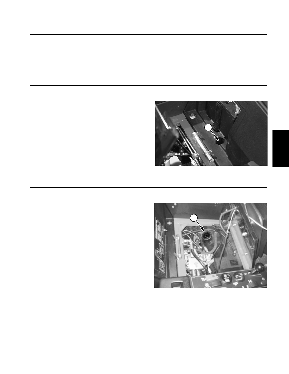
Towing Traction Unit
IMPORTANT: If towing limits are exceeded, severe
damage to the piston pump may occur.
If it becomes necessary to tow (or push) the machine,
tow (or push) in a forward direction only and at a
speed below 3 mph. The piston (traction) pump is
equipped with a by--pass valve that needs to be turned
o
(one quarter turn) for towing. Refer to your Opera-
90
tor’s Manual for additional towing instructions.
1
System
Hydraulic
Check Hydraulic Fluid
The Groundsmaster 4000--D hydraulic system is designed to operate on anti--wear hydraulic fluid. The reservoir holds about 8 gallons (30.3 liters) of hydraulic
fluid. Check level of hydraulic fluid daily. See Operator’s Manual for fluid level checking procedure and oil
recommendations.
Figure 1
1. By--pass valve location
1
Figure 2
1. Hydraulic reservoir cap
Groundsmaster 4000--D Hydraulic SystemPage 4 -- 3
Page 38

Hydraulic Hoses
Hydraulichoses are subject to extremeconditions such
aspressuredifferentialsduring operationandexposure
to weather, sun, chemicals, very warm storage conditionsormishandlingduring operationandmaintenance.
These conditions can cause hose damage and deterioration. Some hoses are more susceptible to these
conditions than others. Inspect all machine hydraulic
hoses frequently for signs of deterioration or damage:
WARNING
Beforedisconnectingorperformingany work on
hydraulic system, relieve all pressure in system.
Operate all hydraulic controls to relieve system
pressure.
Hard, cracked, cut, abraded, charred, leaking or
otherwise damaged hose.
Kinked, crushed, flattened or twisted hose.
Blistered, soft, degraded or loose hose cover.
Cracked, damaged or badly corroded hose fittings.
When replacing a hydraulic hose, be sure that the hose
is straight (not twisted) before tightening the fittings.
This can be done by observing the imprint (layline) on
thehose. Usetwo wrenches; hold the hose straight with
one wrench and tighten the hose swivel nut onto the fitting with the other wrench ( See Hydraulic Hose and
Tube Installation in this section). If the hose has an elbowat oneend,tightenthe swivelnutonthat endbefore
tightening the nut on the straight end of the hose.
For additional hydraulic hose information, refer to Toro
Service Training Book, Hydraulic Hose Servicing (Part
Number 94813SL).
Keepbodyand handsaway frompinholeleaksor
nozzles that eject hydraulic fluid under high
pressure. Use paper or cardboard, not hands, to
search for leaks. Hydraulic fluid escaping under
pressure can have sufficient force to penetrate
the skin and cause serious injury. If fluid is injected into the skin, it must be surgically removed within a few hours by a doctor familiar
withthis typeofinjury.Gangrenemayresult from
such an injury.
Groundsmaster 4000--DHydraulic System Page 4 -- 4
Page 39

Hydraulic Hose and Tube Installation (O--Ring Face Seal Fitting)
1. Makesure threads and sealing surfaces of the hose/
tube and the fitting are free of burrs, nicks, scratches or
any foreign material.
2. Asa preventative measure against leakage, it is recommended that the face seal O--ring be replaced any
time the connection is opened. Make sure the O--ring is
installedandproperly seatedinthefittinggroove.Lightly
lubricate the O--ring with clean hydraulic oil.
3. Place the hose/tube against the fitting body so that
theflatfaceofthehose/tube sleevefullycontactstheO-ring in the fitting.
4. Thread the swivel nut onto the fitting by hand. While
holding the hose/tube with a wrench, use a torque
wrench to tighten the swivel nut to the recommended
installation torque shown in Figure 5. This tightening
process will require the use of an offset wrench (e.g.
crowfoot wrench). Use of an offset wrench will affect
torque wrench calibration due to the effective length
change of the torque wrench. Tightening torque when
usingatorquewrenchwithanoffsetwrenchwillbelower
than the listed installation torque (see Using a Torque
Wrench with an Offset Wrench in the Torque Specificationssection of Chapter 2 --Product Records and Maintenance).
C. Useasecondwrench totightenthenut tothecorrect Flats From Wrench Resistance (F.F.W.R.).The
markingsonthe nutandfittingbodywillverifythatthe
connection has been properly tightened.
Siz e F.F.W.R.
4 (1/4 in. nominal hose or tubing) 1/2 to 3/4
6 (3/8 in.) 1/2 to 3/4
8 (1/2 in.) 1/2 to 3/4
10 (5/8 in.) 1/2 to 3/4
12 (3/4 in.) 1/3 to 1/2
16 (1 in.) 1/3 to 1/2
Swivel Nut
Tube or Hose
O--ring
Fitting Body
Figure 3
System
Hydraulic
5. If a torque wrench is not available or if space at the
swivelnut prevents use of a torquewrench,analternate
method of assembly is the Flats From Wrench Resist-
Mark Nut
and Fitting
Body
Final
Position
ance (F.F.W.R.) method (Fig. 2).
A. Usingawrench,tighten the swivelnutonto thefittinguntillightwrench resistanceisreached (approximately 30 in--lb).
B. Mark the swivel nut and fitting body. Hold the
hose/tube with a wrench to prevent it from turning.
AT WRENCH RESISTANCE
Extend Line
Figure 4
Fitting Dash Size Hose/Tube Side Thread Size Installation Torque
4 9/16 -- 18 18to22ft--lb(25to29N--m)
6 11/16 - - 16 27to33ft--lb(37to44N--m)
8 13/16 -- 16 37to47ft--lb(51to63N--m)
10 1--14 60 to 74 ft--lb (82 to 100 N--m)
12 13/16--12 85 to 105 ft--lb (116 to 142 N--m)
16 17/16--12 110 to 136 ft--lb (150 to 184 N--m)
Initial
Position
AFTER TIGHTENING
20 1 11/16 -- 12 140 to 172 ft--lb (190 to 233 N--m)
Figure 5
Groundsmaster 4000--D Hydraulic SystemPage 4 -- 5
Page 40

Hydraulic Fitting Installation (SAE Straight Thread O--Ring Fitting into Component Port)
Non--Adjustable Fitting (Fig. 6)
1. Make sure all threads and sealing surfaces of fitting
and component port are free of burrs, nicks, scratches
or any foreign material.
2. Asa preventative measure against leakage, it is recommended that the O--ring be replaced any time the
connection is opened.
3. Lightly lubricate the O--ring with clean hydraulic oil.
Fittingthreadsshouldbecleanwith nolubricantapplied.
IMPORTANT: Before installing fitting into port, determine port material. If fitting is to be installed into
an aluminum port, installation torque is reduced.
4. Install the fitting into the port. Then, use a torque
wrench and socket to tighten the fitting to the recommended installation torque shown in Figure 7.
NOTE: Useof an offset wrench (e.g. crowfoot wrench)
will affect torque wrench calibration due to the effective
length change of the torque wrench. Tightening torque
when using a torque wrench with an offset wrench will
be less than the recommended installation torque. See
Using a Torque Wrench with an Offset Wrench in the
Torque Specifications section of Chapter 2 -- Product
Recordsand Maintenancetodetermine necessary conversion information.
5. If a torque wrench is not available, or if space at the
portpreventsuseof atorquewrench, analternatemethod of assembly is the Flats From Finger Tight (F.F.F.T.)
method.
A. Install the fitting into the port and tighten it down
full length until finger tight.
B. If port material is steel, tighten the fitting to the
listed F.F.F.T.If port material is aluminum, tighten fitting to 60% of listed F.F.F.T.
Siz e F.F.F.T.
4 (1/4 in. nominal hose or tubing) 1.00 +
6(3/8in.) 1.50+
8(1/2in.) 1.50+
10 (5/8 in.) 1.50 +
12 (3/4 in.) 1.50 +
16 (1 in.) 1.50 +
Fitting
O--ring
0.25
0.25
0.25
0.25
0.25
0.25
Figure 6
Fitting
Dash Size
Fitting Port Side
Thread Size
Installation Torque Into
Steel Port
Installation Torque Into
Aluminum Port
4 7/16 -- 20 15to19ft--lb(21to25N--m) 9to11ft--lb(13to15N--m)
5 1/2 -- 20 18to22ft--lb(25to29N--m) 11to15ft--lb(15to20N--m)
6 9/16 -- 18 34to42ft--lb(47to56N--m) 20to26ft--lb(28to35N--m)
8 3/4 -- 16 58to72ft--lb(79to97N--m) 35to43ft--lb(48to58N--m)
10 7/8 -- 14 99 to 121 ft--lb (135 to 164 N--m) 60 to 74 ft--lb (82 to 100 N--m)
12 11/16--12 134 to 164 ft--lb (182 to 222 N--m) 81 to 99 ft--lb (110 to 134 N--m)
14 13/16--12 160 to 196 ft--lb (217 to 265 N--m) 96 to 118 ft--lb (131 to 160 N--m)
16 15/16--12 202 to 248 ft--lb (274 to 336 N--m) 121 to 149 ft--lb (165 to 202 N--m)
20 15/8--12 247 to 303 ft--lb (335 to 410 N--m) 149 to 183 ft--lb (202 to 248 N--m)
Figure 7
Groundsmaster 4000--DHydraulic System Page 4 -- 6
Page 41

Adjustable Fitting (Fig. 8)
1. Make sure all threads and sealing surfaces of fitting
and component port are free of burrs, nicks, scratches
or any foreign material.
2. Asa preventative measure against leakage, it is recommended that the O--ring be replaced any time the
connection is opened.
3. Lightly lubricate the O--ring with clean hydraulic oil.
Fittingthreadsshouldbecleanwith nolubricantapplied.
4. Turnback the lock nut as far as possible. Make sure
the back up washer is not loose andis pushed up as far
as possible (Step 1 in Figure 9).
IMPORTANT: Before installing fitting into port, determine port material. If fitting is to be installed into
an aluminum port, installation torque is reduced.
Lock Nut
Back--up Washer
O--ring
Figure 8
5. Install the fitting into the port and tighten finger tight
until the washer contacts the face of the port (Step 2).
6. Toput the fitting in the desired position,unscrew itby
the required amount, but no more than one full turn
(Step 3).
7. Hold the fitting in the desired position with a wrench
and use a torque wrench to tighten the fitting to the recommended installation torque shown in Figure 7. This
tightening process will require the use of an offset
wrench (e.g. crowfoot wrench). Use of an offset wrench
will affect torque wrench calibration due to the effective
length change of the torque wrench. Tightening torque
when using a torque wrench with an offset wrench will
be lower than the listed installation torque (see Using a
Torque Wrench with an Offset Wrench in the Torque
Specifications section of Chapter 2 -- Product Records
and Maintenance).
8. If a torque wrench is not available, or if space at the
portpreventsuseof atorquewrench, analternatemethod of assembly is the Flats From Finger Tight (F.F.F.T.)
method. Hold the fitting in the desired position with a
wrench and, if port material is steel, tighten the lock nut
witha secondwrenchtothe listedF.F.F.T(Step 4).Ifport
material is aluminum, tighten fitting to 60% of listed
F.F.F.T.
Step 3Step 1
Step 2 Step 4
Figure 9
System
Hydraulic
Siz e F.F.F.T.
4 (1/4 in. nominal hose or tubing) 1.00 +
6(3/8in.) 1.50+
8(1/2in.) 1.50+
10 (5/8 in.) 1.50 +
12 (3/4 in.) 1.50 +
16 (1 in.) 1.50 +
0.25
0.25
0.25
0.25
0.25
0.25
Groundsmaster 4000--D Hydraulic SystemPage 4 -- 7
Page 42

Hydraulic Schematic
COUNTERBALANCE
MANIFOLD
TRACTION
4WD
MANIFOLD
MANIFOLD
FILTER
MANIFOLD
VALVE
BYPASS
NOTE: A larger hydraulic schematic is
included in Chapter 9: Foldout Drawings
MANIFOLD
FAN DRIVE
M1 M2 ST L
P1
LC1
RV1
MANIFOLD
RV2
FRONT PTO
M1
P2
S
LC2
M2
P1
LC1
RV1
LH PTO
MANIFOLD
RV2
M1
P2
S
LC2
OR
M2
P1
RV1
RH PTO
RV2
MANIFOLD
M1
P1 P2T
P2
LC1
S
LC2
OR
M2
Groundsmaster 4000--DHydraulic System Page 4 -- 8
Page 43

This page is intentionally blank.
System
Hydraulic
Groundsmaster 4000--D Hydraulic SystemPage 4 -- 9
Page 44

Hydraulic Flow Diagrams
COUNTERBALANCE
MANIFOLD
4WD
MANIFOLD
MANIFOLD
TRACTION
Traction Circuit (4WD Forward Shown)
Groundsmaster 4000--D
Working Pressure
Low Pressure (Charge)
Flow
Return or Suction
MANIFOLD
FAN DRIVE
M1 M2 ST L
P1
LC1
RV1
MANIFOLD
RV2
FRONT PTO
M1
P2
S
LC2
M2
P1
LC1
RV1
LH PTO
MANIFOLD
RV2
M1
P2
S
OR
LC2
M2
P1
RV1
RH PTO
MANIFOLD
RV2
M1
P1 P2T
P2
LC1
S
OR
LC2
M2
Groundsmaster 4000--DHydraulic System Page 4 -- 10
Page 45

Traction Circuit: 4WD (Mow)
The traction circuit piston pump is a variable displacement pump that is directly coupled to the engine flywheel. Pushing the traction pedal engages a hydraulic
servo valve which controls the variable displacement
piston pump swash plate to create a flow of oil. This oil
isdirectedtothefrontwheeland rearaxlemotors.Operating pressure on the high pressure side of the closed
traction circuit loop is determined by the amount of load
developedatthefixeddisplacementwheelandaxlemotors. As the load increases, circuit pressure can increase to relief valve settings: 4000 PSI (274 bar) in
forward and 5000 PSI (343 bar) in reverse. If pressure
exceeds the relief setting, oil flows through the relief
valveto the low pressure side of the closed loop traction
circuit. The traction circuit provides operation in either
4WD (mow) or transport (2WD).
Traction circuit pressure (forward and reverse) can be
measured at test ports on the sides of the machine.
The traction circuit pump and motors use a small
amount of hydraulic fluid for internal lubrication. Fluid is
designed to leak across traction pump and motor components into the case drain. This leakage results in the
lossofhydraulicfluidfromtheclosedloop tractioncircuit
thatmust be replaced. Thecharge circuit is designed to
replace this traction circuit leakage.
The gear pump section that supplies oil to the steering
andlift/lower circuits alsoprovides oil forthe charge circuit. This gear pump is driven directly off the traction
pump. It provides a constant supply of charge oil to
make up for oil that is lost due to internal leakage in the
traction pump and motors.
Pump flow for the charge circuit is directed through the
oil filter and to the low pressure side of the closed loop
traction circuit. A filter bypass valve allows charge oil
flow to the closed loop if the filter becomes plugged.
Chargepressure is limitedto 250 PSI (17 bar) by a relief
valve located in the oil filter manifold. Charge pressure
canbe measured at thechargecircuitpressuretestport
on the oil filter manifold.
Aflowdividerisincorporatedintothetractioncircuitand
islocated in the tractionmanifold. When in 4WD (mow),
the operator can momentarily engage this flow divider
when low traction situations could lead to wheel spin.
Depressing the flow divider switch energizes the solenoid valve in the traction manifold. This energized solenoid valve causes traction pump hydraulic flow to split
between the front wheel motors (approximately 45%)
and rear axle motor (approximately 55%) to reduce the
chance that excessive flow goes to a spinning wheel.
Forward Direction
When the transport/4WD switch is in the 4WD (mow)
position and the traction pedal is pushed in the forward
direction, oil from the piston pump passes through the
tractionmanifold. Oil flow from traction manifold portM1
drives the front wheel motors in the forward direction
and then returns to the hydrostat. Oil flow from traction
manifold port M2 is routed to the P1 port of the 4WD
manifoldwhereitisdirectedtothePD1cartridgeandout
ofthe manifoldtodrivethe rearaxlemotorin theforward
direction.Oil returning fromtherear motor re--entersthe
4WD manifold at the M2 port. Flow passes through the
PD2cartridge,throughtheCVcheck valve,outmanifold
port P2 and back to the hydrostat.
When going down a hill, the tractor becomes an over-running load that drives the wheel and axle motors. In
this condition, the rear axle motor could lock up as the
oil pumped from the motor increases pressure as it returnsto the hydrostat. Toprevent rear wheel lock up, an
adjustable relief valve (RV) in the 4WD manifold reducesrear axle motor pressure created indown hill, dynamic braking conditions.
Reverse Direction
The traction circuit operates essentially the same in reverse 4WD (mow) as it does in the forward direction.
However,theflowthroughthecircuitisreversed.Oilflow
from the hydrostat is directed to the front wheel motors
and also to the 4WD manifold. The oil to the front wheel
motorsdrives them in the reverse direction and then returnstothehydrostatthroughthe traction manifold. The
oil to the 4WD manifold enters the manifold at port P2
and flows through pressure reducing valve (PR) which
limits the down stream pressure to the rear axle motor
to 650 PSI (45 bar) so the rear wheels will not scuff the
turf during reverse operation. This reduced pressure
flows through the PD2 cartridge and out port M2 to the
rearaxle motor.Return oil fromtherearmotor re--enters
the4WDmanifoldat portM1,flowsthroughthePD1cartridge,exitsthemanifold atportP1andreturns tothehydrostat.
System
Hydraulic
Groundsmaster 4000--D Hydraulic SystemPage 4 -- 11
Page 46

COUNTERBALANCE
MANIFOLD
(shifted)
(shifted)
(energized)
(extended)
4WD
MANIFOLD
MANIFOLD
TRACTION
Traction Circuit (Transport Forward Shown)
Groundsmaster 4000--D
Working Pressure
Low Pressure (Charge)
Flow
Return or Suction
MANIFOLD
FAN DRIVE
M1 M2 ST L
P1
LC1
RV1
MANIFOLD
RV2
FRONT PTO
M1
P2
S
LC2
M2
P1
LC1
RV1
LH PTO
MANIFOLD
RV2
M1
P2
S
OR
LC2
M2
P1
RV1
RH PTO
MANIFOLD
RV2
M1
P1 P2T
P2
LC1
S
OR
LC2
M2
Groundsmaster 4000--DHydraulic System Page 4 -- 12
Page 47

Traction Circuit: Transport (2WD)
The traction circuit piston pump is a variable displacement pump that is directly coupled to the engine flywheel. Pushing the traction pedal engages a hydraulic
servo valve which controls the variable displacement
piston pump swash plate to create a flow of oil. This oil
isdirectedtothefrontwheeland rearaxlemotors.Operating pressure on the high pressure side of the closed
traction circuit loop is determined by the amount of load
developedatthefixeddisplacementwheelandaxlemotors. As the load increases, circuit pressure can increase to relief valve settings: 4000 PSI (274 bar) in
forward and 5000 PSI (343 bar) in reverse. If pressure
exceeds the relief setting, oil flows through the relief
valveto the low pressure side of the closed loop traction
circuit. The traction circuit provides operation in either
4WD (mow) or transport (2WD).
Traction circuit pressure (forward and reverse) can be
measured at test ports on the sides of the machine.
The traction circuit pump and motors use a small
amount of hydraulic fluid for internal lubrication. Fluid is
designed to leak across traction pump and motor components into the case drain. This leakage results in the
lossofhydraulicfluidfromtheclosedloop tractioncircuit
thatmust be replaced. Thecharge circuit is designed to
replace this traction circuit leakage.
The gear pump section that supplies oil to the steering
and lift/lower circuits also provides charge oil for the
traction circuit. This gear pump is driven directly off the
tractionpump.Itprovidesaconstantsupplyof chargeoil
to the traction circuit to make up for oil that is lost due to
internal leakage in the traction pump and motors.
Chargepumpflowisdirected through the oil filter and to
the low pressure side of the closed loop traction circuit.
A filter bypass valve allows charge oil flow to the closed
loopif thefilter becomesplugged.Chargepressureislimited to 250 PSI (17 bar) by a relief valve located in the
oil filter manifold. Charge pressure can be measured at
thechargecircuit pressure test port on theoilfiltermanifold.
Forward Direction
Withthe transport/4WD switch in the transport position,
solenoidvalve (SV) in the 4WD control manifold is energized. The solenoid valve spool shifts to direct charge
pressure that shifts the PD1 and PD2 control valve
spools. The shifted PD1 valve prevents hydraulic flow
from the piston pump to the rear axle motor. With flow
blocked to the rear axle motor,all pump flow is directed
to the front wheel motors to allow a higher transport
speed in the forward direction.
Without flow to the rear axle motor, the rotating rear
wheels drive the axle motor so it acts like a pump. Inlet
oilto the axle motor isprovided by a checkvalve that allows charge oil into the rear axle motor circuit. Oil leaving the axle motor enters the 4WD control manifold at
port M2 and is directed back to the axle motor through
theshifted PD1 cartridge and manifold portM1.Toallow
forrearwheelloopcoolingwheninforward transportoperation, a small amount of oil exits through the shifted
PD1 and PD2 cartridges that returns to the reservoir.
A transport cylinder is included in the traction circuit to
reduce traction control arm movement on the piston
pumpwhen operating intransport (2WD). This reduced
armmovement limitsswashplaterotation to preventexcessive transport speed.
Thetraction manifoldflowdividercannot beengagedby
the operator during transport (2WD) operation.
Reverse Direction
The traction circuit operates essentially the same in reversetransport(2WD)asitdoesintheforwarddirection.
However, the flow through the circuit is reversed. The
shifted solenoid valve (SV) and directional valves PD1
and PD2 in the 4WD manifold prevent oil flow from the
rear axle motor.Oil flow from the hydrostat is therefore
directed to only the front wheel motors. This oil drives
the front wheel motors in the reverse direction and then
returns to the hydrostat. Oil circulation through the rear
axle motor loop is the same as in the transport (2WD)
forward direction.
System
Hydraulic
Groundsmaster 4000--D Hydraulic SystemPage 4 -- 13
Page 48

COUNTERBALANCE
MANIFOLD
4WD
MANIFOLD
MANIFOLD
TRACTION
Groundsmaster 4000--D
Working Pressure
Low Pressure (Charge)
Lower Cutting Unit (LH Deck Shown)
Flow
Return or Suction
MANIFOLD
FAN DRIVE
M1 M2 ST L
P1
LC1
RV1
MANIFOLD
RV2
FRONT PTO
M1
P2
S
LC2
M2
P1
LC1
RV1
LH PTO
MANIFOLD
RV2
M1
P2
S
OR
LC2
M2
P1
RV1
RH PTO
MANIFOLD
RV2
M1
P1 P2T
P2
LC1
S
OR
LC2
M2
Groundsmaster 4000--DHydraulic System Page 4 -- 14
Page 49

Lower Cutting Deck
A four section gear pump is coupled to the piston (traction) pump. The third gear pump section supplies hydraulic flow to both the lift/lower control valve and the
steering control valve. Hydraulic flow from this pump
section is delivered to the steering and lift/lower circuits
through a proportional flow divider that is located in the
fan drive manifold. This pump section takes its suction
from the hydraulic reservoir.
Whenthecutting decks are in a stationaryposition,flow
from the gear pump is by--passed through the lift/lower
control valve, counterbalance manifold, oil filter and
traction charge circuit.
Tolower a side cuttingdeck, the appropriate liftlever on
the lift/lower control valve is pushed to allow valve shift
in the lift/lower control valve. This valve change causes
a valve shift in the counterbalance manifold and oil flow
to the rod end of the lift cylinder.Higher hydraulic pressureagainsttherodend ofthecylinder causes thecylinder shaft to retract, and lower the cutting deck. Oil from
the piston end of the cylinder returns to the traction
chargecircuit. When the liftlever is released, the lift cylinder and side cutting deck are held in position.
Tolower the frontcuttingdeck,the center lift lever onthe
lift/lowercontrolvalveispushedtoallowvalveshiftinthe
lift/lowercontrol.Thisvalvechangeallowsapassagefor
oil flow from the rod end of the front deck lift cylinders.
The weight of the cutting deck causes the lift cylinders
to extend, and lower the cutting deck. Oil from the rod
end of the cylinders is allowed to return to the traction
chargecircuit. When the liftlever is released, the lift cylinders and cutting deck are held in position.
The drop speed of the front cutting deck is regulated by
anadjustableflow control valve that is locatedin the hydraulic lines between the lift/lower control valve and the
front deck lift cylinders.
Anadjustablecounterbalancevalve(CB)inthecounterbalance manifold maintains back pressure on the deck
lift cylinders to allow some of the cutting deck weight to
be transferred to the traction unit to improve traction. A
reliefvalve locatedinthelift/lower controlvalvelimitslift/
lowercircuitpressure to 1500 PSI (103 bar). Excess circuit flow is routed to the oil filter and then to the traction
charge circuit.
System
Hydraulic
Groundsmaster 4000--D Hydraulic SystemPage 4 -- 15
Page 50

COUNTERBALANCE
MANIFOLD
4WD
MANIFOLD
MANIFOLD
TRACTION
Groundsmaster 4000--D
Working Pressure
Low Pressure (Charge)
Raise Cutting Unit (LH Deck Shown)
Flow
Return or Suction
MANIFOLD
FAN DRIVE
P1 P2T
M1 M2 ST L
P1
LC1
RV1
MANIFOLD
RV2
FRONT PTO
M1
P2
S
LC2
M2
P1
LC1
RV1
LH PTO
MANIFOLD
RV2
M1
P2
S
OR
LC2
M2
P1
LC1
RV1
RH PTO
MANIFOLD
RV2
M1
P2
S
OR
LC2
M2
Groundsmaster 4000--DHydraulic System Page 4 -- 16
Page 51

Raise Cutting Deck
A four section gear pump is coupled to the piston (traction) pump. The third gear pump section supplies hydraulicflowtothelift/lowercontrolvalveandthesteering
control valve. Hydraulic flow from this pump section is
delivered to the two circuits through a proportional flow
divider. The gear pump takes its suction from the hydraulic reservoir.
Whenthecutting decks are in a stationaryposition,flow
from the gear pump is by--passed through the lift/lower
control valve, counterbalance manifold, oil filter and
traction charge circuit.
To raise a side cutting deck, the appropriate lift lever on
thelift/lower control valve is pulled to allow valveshift in
thelift/lowercontrol valve. This valve changeallows hydraulic pressure to the piston end of the lift cylinder and
causes the cylinder shaft to extend, raising the cutting
deck. Oil from the rod end of the cylinder flows to the
tractionchargecircuit.Whentheliftleverisreleased,the
lift cylinder and cutting deck are held in position.
Toraisethe front cutting deck, the centerliftleveron the
lift/lower control valve is pulled to allow valve shiftin the
lift/lower control valve. This valve change allows hydraulicpressuretotherod end of the front deck lift cylinders, causing the cylinders to retract. As the cylinders
retract, the front deck raises. Oil from the piston end of
the cylinders returns to the hydraulic reservoir. When
theliftleverisreleased,theliftcylinders andcuttingdeck
are held in position.
Anadjustablecounterbalancevalve(CB)inthecounterbalance manifold maintains back pressure on the deck
lift cylinders to allow some of the cutting deck weight to
be transferred to the traction unit to improve traction. A
reliefvalve locatedinthelift/lower controlvalvelimitslift/
lowercircuitpressure to 1500 PSI (103 bar). Excess circuit flow is routed to the oil filter and then to the traction
charge circuit.
System
Hydraulic
Groundsmaster 4000--D Hydraulic SystemPage 4 -- 17
Page 52

COUNTERBALANCE
MANIFOLD
4WD
MANIFOLD
MANIFOLD
TRACTION
Mow (Front Deck Shown)
Groundsmaster 4000--D
Working Pressure
Low Pressure (Charge)
Flow
Return or Suction
MANIFOLD
FAN DRIVE
M1 M2 ST L
P1
LC1
RV1
MANIFOLD
RV2
FRONT PTO
M1
P2
S
LC2
M2
P1
LC1
RV1
LH PTO
MANIFOLD
RV2
M1
P2
S
OR
LC2
M2
P1
RV1
RH PTO
MANIFOLD
RV2
M1
P1 P2T
P2
LC1
S
OR
LC2
M2
Groundsmaster 4000--DHydraulic System Page 4 -- 18
Page 53

Mow
Hydraulicflow for themowcircuitis supplied by twosections of the gear pump. The gear pump section closest
to the piston (traction) pump supplies hydraulic flow to
theside cutting decks, while the next gear pump section
supplies the front cutting deck.
Each cutting deck is controlled by a hydraulic manifold
equipped with a solenoid control valve (S), bypass cartridge (LC1), brake cartridge (LC2) and relief cartridge
(RV1).Whenthethedeck solenoidvalve(S)is not energized (PTO switch OFF), hydraulic flow by--passes the
deck motor through the bypass cartridge (LC1). When
the PTO switch is turned ON, the solenoid valve (S) energizes, causing a shift of the by--pass cartridge (LC1)
andallowinghydraulicflowtothe deckmotor.Brakecartridge (LC2) and relief cartridge (RV2) control the stoppingrate of theblade when thesolenoid control valveis
de--energized as the PTO switch is turned OFF.
Returnoilfromthedeckmotorsisdirectedtotheoilcooler and oil filter. Deck motor case drain leakage returns
to the hydraulic reservoir.
Maximum mow circuit pressure is limited at each deck
by a relief valve (RV1) in the hydraulic manifold. The
front and left deck relief valves are setat 3000 PSI (207
bar)andtherightdeckreliefvalveissetat2000PSI(137
bar).
Circuit pressure can be measured at port (G) of the hydraulic manifold for each cutting deck.
System
Hydraulic
Groundsmaster 4000--D Hydraulic SystemPage 4 -- 19
Page 54

PTO Mow Circuit Cutting Deck Blade Braking
WhentheoperatorturnsthePTOswitchOFForifadeck
is raised with the PTO switch ON, PTO control manifold
solenoid valve (S) is de--energized causing logic cartridge(LC1)toshift(refertoinformationinPTOMowCircuit in this section). This shifted cartridge allows oil
return out manifold port P2. At the same time, solenoid
valve (S) in its neutral position prevents any sense line
flow through the spool which causes the logic cartridge
LC2 to shift to its neutral position blocking return flow
fromthe deck motor andslowingthecuttingblades (Fig.
10).
Theinertiaofthe rotatingcuttingblades,however,effec-
tively turns the deck motor into a pump causing an increasein pressure as theflow from the motor comesup
againsttheclosed logiccartridge(LC2).Whenthispressure builds to approximately 600 PSI (41 bar), relief
valve (RV2) opens which allows a small amount of hydraulic flow to return to tank througha manifold sensing
line (Fig. 11). This flow causes a pressure increase that
shifts logic cartridge LC2 to once again allow oil flow
from the motor (Fig. 12). When return pressure drops
below 600 PSI (41 bar), relief valve (RV2) reseats and
causesLC2 to close again blocking return flow from the
deckmotortofurther slowthecuttingblades.This action
of the brake relief valveopening and the logic cartridge
shifting occurs several times in a very short time frame
as the blades finally come to a stop. Once the blades
havestopped, logiccartridgeLC2remains in theneutral
position to keep the deck motor from rotating.
DECK
MOTOR
DECK
MOTOR
PTO MANIFOLD
M1
RV2
M2
PTO MANIFOLD
M1
RV2
M2
RV1
LC2
Figure 10
RV1
LC2
G
P1
LC1
S
P2
CD
G
P1
LC1
S
P2
DECK
MOTOR
PTO MANIFOLD
M1
RV2
M2
Figure 11
RV1
LC2
Figure 12
CD
G
P1
LC1
S
P2
CD
Groundsmaster 4000--DHydraulic System Page 4 -- 20
Page 55

This page is intentionally blank.
System
Hydraulic
Groundsmaster 4000--D Hydraulic SystemPage 4 -- 21
Page 56

COUNTERBALANCE
MANIFOLD
4WD
MANIFOLD
MANIFOLD
TRACTION
Groundsmaster 4000--D
Working Pressure
Low Pressure (Charge)
Steering Circuit (Left Turn Shown)
Flow
Return or Suction
MANIFOLD
FAN DRIVE
M1 M2 ST L
P1
LC1
RV1
MANIFOLD
RV2
FRONT PTO
M1
P2
S
LC2
M2
P1
LC1
RV1
LH PTO
MANIFOLD
RV2
M1
P2
S
LC2
OR
M2
P1
RV1
RH PTO
MANIFOLD
RV2
M1
P1 P2T
P2
LC1
S
LC2
OR
M2
Groundsmaster 4000--DHydraulic System Page 4 -- 22
Page 57

Steering Circuit
A four section gear pump is coupled to the piston (traction) pump. The third gear pump section supplies hydraulicflowtothesteeringcontrolvalveandthelift/lower
controlvalve.Pumphydraulicflowisdelivered tothe two
circuitsthroughaproportionalflow dividerlocated in the
fandrive manifold.Thegearpump takesitssuctionfrom
thehydraulicreservoir.Steering circuit pressure is limited to 1350 PSI (93 bar) by a relief valve located in the
steering control.
With the steering wheel in the neutral position and the
enginerunning, flow enters thesteering control valve at
the P port and goes through the steering control spool
valve, by--passing the rotary meter (V1) and steering
cylinder. Flow leaves the control valve through the PB
port to the oil filter and traction charge circuit.
Left Turn
When a left turn is made with the engine running, the
turningofthesteeringwheelpositionsthespoolvalveso
thatflowgoesthroughthetopofthespool.Flowentering
thesteering control valve at the P port goes throughthe
spool and is routed to two places. First, most of the flow
through the valve is by --passed out the PB port back to
the oil filter and traction charge circuit. Second, the remainder of the flow is drawn through the rotary meter
(V1) and out the L port. Pressure contracts the steering
cylinder piston for a left turn. The rotary meter ensures
that the oil flow to the cylinder is proportional to the
amount of the turning on the steering wheel. Fluid leavingthe cylinder flows back through the spool valvethen
through the T port and to the hydraulic reservoir.
Thesteeringcontrolvalvereturnstotheneutralposition
when turning is completed.
Right Turn
When a right turn is made with the engine running, the
turningofthesteeringwheelpositionsthespoolvalveso
thatflow goes through thebottom of the spool.Flow entering the steering control valve at the P port goes
throughthe spool and is routed to twoplaces.Asinaleft
turn,mostoftheflow throughthevalveis by--passed out
the PB port back to the oil filter and traction charge circuit. Also like a left turn, the remainder of the flow is
drawn through rotary meter (V1) but goes out port R.
Pressureextends the steering cylinder piston for a right
turn.The rotary meterensuresthattheoil flow to thecylinder is proportional to the amount of the turning on the
steering wheel. Fluid leaving the cylinder flows back
through the spool valve then through the T port and to
the hydraulic reservoir.
Thesteeringcontrolvalvereturnstotheneutralposition
when turning is completed.
System
Hydraulic
STEERING CYLINDER
NO PISTON MOVEMENT
R
T
NEUTRAL POSITION
L
1350
PSI
PB
P
STEERING
CONTROL
STEERING CYLINDER
PISTON MOVEMENT
R
T
LEFT TURN
L
1350
PSI
PB
P
Figure 13
STEERING
CONTROL
STEERING CYLINDER
PISTON MOVEMENT
R
T
RIGHT TURN
L
1350
PSI
PB
P
STEERING
CONTROL
Groundsmaster 4000--D Hydraulic SystemPage 4 -- 23
Page 58

COUNTERBALANCE
MANIFOLD
4WD
MANIFOLD
MANIFOLD
TRACTION
Groundsmaster 4000--D
Working Pressure
Low Pressure (Charge)
Engine Cooling Fan Circuit (Forward Direction Shown)
Flow
Return or Suction
MANIFOLD
FAN DRIVE
M1 M2 ST L
P1
LC1
RV1
MANIFOLD
RV2
FRONT PTO
M1
P2
S
LC2
M2
P1
LC1
RV1
LH PTO
MANIFOLD
RV2
M1
P2
S
OR
LC2
M2
P1
RV1
RH PTO
MANIFOLD
RV2
M1
P1 P2T
P2
LC1
S
OR
LC2
M2
Groundsmaster 4000--DHydraulic System Page 4 -- 24
Page 59

Engine Cooling Fan Circuit
A four section gear pump is coupled to the piston (traction)pump. Thegearpump sectionfarthestfrom thepiston pump supplies hydraulic flow for the fan drive
manifold and hydraulic engine cooling fan motor (Fig.
14).
The fan drive manifold controls the operation of the hy-
draulic motor that drives the engine cooling fan in addition to including the flow divider for the steering and lift
circuits. The electronically controlled proportional relief
valve(PRV)inthemanifoldcontrolstheoilflowtothefan
motor.Thefandrivemanifoldcontrols the speed and direction of the fan motor based on electrical output from
the TEC--5002 controller.
Oil flow from the gear pump to the cooling fan motor is
controlled by the proportional relief valve (PRV) in the
fan drive manifold. This valve adjusts fan circuit pressure and flow based on a PWM (Pulse Width Modulation)signalfromtheTEC--5002controller.Thecontroller
uses engine coolant and hydraulic oil temperatures as
inputstodeterminetheproperPWMsignalfor the(PRV)
valve. The fan circuit flow determines the speed of the
coolingfan motor and thus, the speed ofthecoolingfan.
If the fan motor is stalled for any reason, the manifold
proportionalreliefvalve(PRV) hasasecondary function
as a circuit relief to limit fan motor pressure to 3000 PSI
(207 bar).
When the engine is shut off, the over--running inertia
load of the fan blades keeps driving the fan motor and
turnsitintoapump.Thecheckvalve(CV)inthefandrive
manifold will open to keep the motor circuit full of oil so
the fan motor will not cavitate.
Forward Direction Fan Operation
runsin thereversedirection. A lowerPWMsignal is sent
tothe PRVvalveallowingoilflowtoreturntothe fan motor but in the reverse direction causing the motor and
cooling fan to run in reverse. The controller determines
the length of time that the fan should be run in reverse
before fan rotation is returned to the forward direction.
2
1
Figure 14
1. Gear pump 2. Fan drive manifold
REVERSE DIRECTION SHOWN
TO RESERVOIR
TO STEERING
CIRCUIT
M1 M2 L
TO LIFT/LOWER
CIRCUIT
System
Hydraulic
Oilflowfromthe gearpumpis sentthroughthede--energizedsolenoid valve(S1)to rotatethecooling fanmotor.
Return flow from the motor re--enters the manifold (port
M2),through the de--energizedsolenoid valve (S1), out
ofthe manifold (port T) andthenisroutedthroughtheoil
cooler and oil filter.
Reverse Direction Fan Operation (Fig. 15)
TheTEC--5002 controller can reverse thecoolingfanto
clean debris from the radiator, oil cooler and rear intake
screen. If hydraulic oil and/or engine coolant temperaturesincrease to an unsuitablelevel,ahigh PWM signal
is sent to the(PRV) valve to slow the cooling fanand direct pump oil flow to the reservoir. The controller then
energizes solenoid valve (S1) in the fan drive manifold
to reverse cooling fan motor oil flow so that the motor
Groundsmaster 4000--D Hydraulic SystemPage 4 -- 25
P1 P2T
TO OIL COOLER
Figure 15
FAN DRIVE
MANIFOLD
FROM GEAR PUMP
Page 60

Special Tools
Order these special tools from your Toro Distributor.
Hydraulic Pressure Test Kit
Use to take various pressure readings for diagnostic
tests. Quick disconnect fittings provided attach directly
to mating fittings on machine test ports without tools. A
high pressure hose is provided for remote readings.
Contains one each: 1000 PSI (70 Bar), 5000 PSI (350
Bar) and 10000 PSI (700 Bar) gauges. Use gauges as
recommended in the Testing section of this chapter.
Toro Part Number: TOR47009
Figure 16
Hydraulic Tester (Pressure and Flow)
This tester requires O--ring Face Seal (ORFS) adapter
fittings for use on this machine.
1. INLET HOSE: Hose connected from the system circuit to the inlet side of the hydraulic tester.
2. LOAD VALVE: A simulated working load is created
in the circuit by turning the valve to restrict flow.
3. PRESSUREGAUGE:Glycerinefilled0to5000PSI
gauge to provide operating circuit pressure.
4. FLOW METER: This meter measures actual oil flow
in the operating circuit with a gauge rated from 1 to 15
GPM(5to55LPM).
5. OUTLET HOSE: A hose from the outlet side of the
hydraulictester connects to the hydraulic system circuit.
6. FITTINGS:An assortment of hydraulicfittingsareincluded with this kit.
Toro Part Number: TOR214678
Figure 17
Rev. A
Groundsmaster 4000--DHydraulic System Page 4 -- 26
Page 61

Hydraulic Test Fitting Kit
This kit includes avariety of O--ring Face Seal fittings to
enable you to connect test gauges into the system.
The kit includes: tee’s, unions, reducers, plugs, c aps
and male test fittings.
Toro Part Number: TOR4079
Measuring Container
Use this container for doing hydraulic motor efficiency
testing(motors with case drain lines only).Measureefficiency of a hydraulic motor by restricting the outlet flow
from the motor and measuring leakage from the case
drainline while themotorispressurizedby the hydraulic
system.
TORO TEST FITTING KIT (NO. TOR4079)
Figure 18
System
Hydraulic
The table in Figure 20 provides gallons per minute
(GPM)conversionformeasuredmilliliterorouncemotor
case drain leakage.
Toro Part Number: TOR4077
Figure 19
Figure 20
Groundsmaster 4000--D Hydraulic SystemPage 4 -- 27
Page 62

Troubleshooting
The charts that follow contain suggestions to assist in
troubleshooting. There may possibly be more than one
cause for a machine malfunction.
Refer to the Testing section of this Chapter for precautions and specific test procedures.
Problem Possible Cause
Hydraulic system operates hot.
NOTE: An indication that the hy-
draulic system is operating at excessive temperatures would be frequent
reversing of the cooling fan and a
normal engine coolant temperature.
Engine RPM is too low.
Brakes are applied or sticking.
Hydraulic reservoir oil level is low.
Hydraulic oil is contaminated or the wrong type.
Piston pump by--pass valve is open or damaged.
Cooling system is not operating properly.
Charge pressure is low.
Traction circuit pressure is incorrect.
NOTE: Whentroubleshooting tractionproblems on the
Groundsmaster 4000--D, if a problem exists in both
4WD and transport speeds, consider a faulty component that affects the entire traction circuit (e.g. charge
circuit, relief valves, piston pump, front wheel motors).
Ifthe problem exists in 4WD but not in transport,consider a problem in the 4WD traction system (e.g. rear axle
motor, 4WD manifold).
Pump(s) or motor(s) are damaged.
Hydraulic oil in reservoir foams. Hydraulic reservoir oil level is low.
Wrong type of oil is in the hydraulic system.
Air is leaking into a pump suction line.
Machine operates in one direction
only.
Traction pedal is sluggish. Traction control linkage is stuck or binding.
Machine travels too far before stopping when the traction pedal is released.
Traction control linkage is faulty.
Traction relief valve is defective.
Charge pressure is low.
Piston (traction) pump servo control valve orifices are plugged or
damaged.
4WD manifold PD1 and PD2 pilot directional valves seals are leaking
or damaged.
Traction linkage is out of adjustment.
Charge pressure is low.
Piston (traction) pump servo control valve orifices are plugged or da-
maged.
Traction pedal does not return to neutral.
Groundsmaster 4000--DHydraulic System Page 4 -- 28
Page 63

Problem Possible Causes
Traction power is lost or unit will not
Hydraulic reservoir oil level is low.
operate in either direction.
Piston pump by--pass valve is open or damaged.
Charge pressure is low.
Traction circuit pressure is low.
Front wheel motor couplers are damaged.
Four wheel drive will not engage. Electrical problem exists (see Chapter 5 -- Electrical System).
Solenoid valve (SV) in 4WD hydraulic manifold is faulty.
Cartridge valve(s) in 4WD manifold is faulty.
Drive gear on rear axle motor or driven gear for rear axle is loose or
damaged.
Rear axle motor is damaged.
Four wheel drive will not disengage. Electrical problem exists (see Chapter 5 -- Electrical System).
Solenoid valve (SV) in 4WD hydraulic manifold is faulty.
Cartridge valve in 4WD manifold is damaged or sticking.
System
Hydraulic
No cutting decks will operate. Electrical problem exists (see Chapter 5 -- Electrical System).
Gear pump or its coupler is damaged (NOTE: other hydraulic circuits
impacted as well).
One cutting deck will not operate. Electrical problem exists (see Chapter 5 -- Electrical System).
System pressure to the affected deck is low.
Woodruff key on affected deck motor is damaged.
Solenoid valve (S) in deck manifold is faulty.
Cartridge valve in deck manifold is damaged or sticking.
Deck motor or gear pump section is damaged.
All cutting decks operate slowly. Engine RPM is low.
Deck motor or gear pump sections are damaged.
Cutting deck stops under load. Relief valve in deck manifold is by--passing.
Deck motor has internal leakage (by --passing oil).
Cutting deck gear pump section is inefficient.
Groundsmaster 4000--D Hydraulic SystemPage 4 -- 29
Page 64

Problem Possible Causes
Cutting decks will not raise. Engine RPM is too low.
Hydraulic oil level in reservoir is low.
Lift arm pivots are binding.
Relief valve in lift/lower control valve is stuck.
Pilot valve in lift/lower control valve is damaged or sticking.
Lift cylinder(s) is (are) damaged.
Gear pump section for lift/lower control valve is inefficient.
Cutting decks raise, but will not stay
Lift circuit lines or fittings are leaking.
up.
Lift cylinder is damaged.
NOTE: Lift cylinders cannot provide
an absolutely perfect seal. The cut-
Detents in lift/lower control valve are worn.
ting deck will eventually lower if left
in the raised position during storage.
Front cutting deck drops too fast or
Flow control valve is not adjusted properly.
too slow.
Cutting decks will not lower. Lift arm pivots are binding.
Counterbalance pressure is excessive.
Pilot valve in lift/lower control valve is damaged or sticking.
Lift cylinder is damaged.
Lift/lower control valve is worn or damaged.
Groundsmaster 4000--DHydraulic System Page 4 -- 30
Page 65

Testing
The most effective method for isolating problems in the
hydraulic system is by using hydraulic test equipment
suchaspressure gauges and flow metersin the circuits
during various operational checks (See the Special
Tools section in this Chapter).
Before Performing Hydraulic Tests
IMPORTANT: All obvious areas such as oil supply,
filter,binding linkages, loose fasteners or improper
adjustmentsmustbecheckedbeforeassuming that
ahydraulic componentis the sourceof theproblem.
Precautions for Hydraulic Testing
WARNING
Before disconnecting or performing any work
on the hydraulic system, all pressure in the
system must be relieved and all rotating machine parts must be stopped. Stop engine;
lower or support attachments.
1. Clean machine thoroughly before disconnecting or
disassemblingany hydraulic components. Always keep
in mind the need for cleanliness when working on hydraulic equipment. Contamination will cause excessive
wear of components.
CAUTION
Failure to use gauges with recommended pressure (PSI) rating as listed in test procedures
couldresult indamage to thegauge andpossible
personal injury from leaking hot oil.
CAUTION
All testing should be performed by two (2)
people.One personshouldbe in theseat to operate the machine, and the other should read and
record test results.
CAUTION
Operate all hydraulic controls to relieve system
pressure and avoid injury from pressurized hydraulic oil. Controls must be operated with the
ignitionswitch in OFF. Removekeyfrom the ignition switch.
2. Put metal caps or plugs on any hydraulic lines left
open or exposed during testing or removal of components.
3. Theenginemust beingoodoperatingcondition.Use
a phototac when performing a hydraulic test. Engine
speed can affect the accuracy of the tester readings.
Check actual speed of the pump when performing flow
testing.
4. When using the hydraulic tester with pressure and
flow capabilities, the inlet and the outlet hoses must be
properly connected and not reversed to prevent damage to the hydraulic tester or components.
5. When using the hydraulic tester with pressure and
flow capabilities, completely open load valve in the tester before starting the engine to minimize the possibility
of damaging components.
6. Install fittings finger tight and far enough to make
sure that they are not cross--threaded before tightening
them with a wrench.
7. Position tester hoses to prevent rotating machine
partsfrom contacting and damaging thehosesortester.
System
Hydraulic
8. Check oil level in the hydraulic reservoir. After con-
WARNING
Keepbodyandhands awayfrom pinholeleaks
ornozzles that eject hydraulic fluid under high
pressure. Do not use hands to search for
leaks; use paper or cardboard. Hydraulic fluid
escaping under pressure can have sufficient
force to penetrate the skin and cause serious
injury. If fluid is injected into the skin, it must
be surgically removed within a few hours by a
doctor familiar with this type of injury. Gangrene may result from such an injury.
Groundsmaster 4000--D Hydraulic SystemPage 4 -- 31
necting test equipment, make sure tank is full.
9. Check control linkages for improper adjustment,
binding or broken parts.
10.After installing test gauges, run engine at low speed
and check for any hydraulic oil leaks.
11.All hydraulic tests should be madewiththehydraulic
oil at normal operating temperature.
12.Before returningmachine to use, makesure that hydraulic reservoir has correct fluid level.
Page 66

Traction Circuit Charge Pressure (Using Pressure Gauge)
FROM COUNTERBALANCE
MANIFOLD
FROM FRONT DECK
CYLINDERS
4WD
MANIFOLD
FROM STEERING VALVEPORT PB
FROM STEERING VALVEPORT T
FROM FRONT PTO MANIFOLD
TO PTO (MOW) CIRCUIT
TO PTO (MOW) CIRCUIT
TO STEERING & LIFT CIRCUITS
TO COOLING FAN CIRCUIT
TRACTION
PRESSURE
GAUGE
MANIFOLD
FILTER
MANIFOLD
FROM PTO MANIFOLDS & FAN MOTOR
FROM PTO MANIFOLDS
Groundsmaster 4000--DHydraulic System Page 4 -- 32
Page 67

ProcedureforTractionCircuitChargePressureTest
1. Make sure hydraulic oil is at normal operating temperatureby operatingthe machine for approximately 10
minutes. Make sure the hydraulic tank is full.
2. Park machine on a level surface with the cutting
decks lowered and off. Make sure engine is off and the
parking brake is applied.
3. Raise and support operator seat.
CAUTION
1
Prevent personal injury and/or damage to equipment. Read all WARNINGS, CAUTIONS and Precautions for Hydraulic Testing at the beginning
of this section.
4. Connect a 1000 PSI (70 bar) pressure gauge onto
charge pressure test port on filter manifold (Fig. 21).
5. Start the engine and put throttle at full engine speed
(2870 RPM) with no load on the hydraulic system.
GAUGEREADINGTOBE200 to 300 PSI (13.8 to
20.6 bar).
6. Stop engine and record test results.
7. If there is no pressure or pressure is low, check for
restrictioninpumpintakeline.Also,inspectchargerelief
valve located in filter manifold (see Hydraulic Manifold
Service: Filter Manifold in the Service and Repairs sectionofthischapter).Ifnecessary,checkforinternaldamage or worn parts in gear pump.
8. Also, with the pressure gauge still connected to the
charge pressure test port, take a gauge reading while
operating the machine in forward and reverse. Start the
engineand put throttle atfullenginespeed (2870 RPM).
Apply the brakes and push the traction pedal forward,
then reverse.
Figure 21
1. Charge pressure port 2. Filter manifold
2
System
Hydraulic
GAUGEREADINGTOBE200 to 300 PSI (13.8 to
20.6 bar).
9. If pressure is good under no load, but consistently
drops below specification when under traction load, the
piston pump and/or traction motor(s) should be suspected of wear and inefficiency. When the pump and/or
traction motor(s) are worn or damaged, the charge
pumpis not able to keep upwithinternalleakagein traction circuit components.
10.When testing is completed, disconnect pressure
gauge from test port.
Groundsmaster 4000--D Hydraulic SystemPage 4 -- 33
Page 68

Traction Circuit Relief Pressure (Using Pressure Gauge)
FORWARD TRACTION CIRCUIT RELIEF PRESSURE TEST SHOWN
FROM COUNTERBALANCE
MANIFOLD
FROM FRONT DECK
CYLINDERS
PRESSURE
GAUGE
FROM STEERING VALVEPORT PB
FROM STEERING VALVEPORT T
FROM FRONT PTO MANIFOLD
TO PTO (MOW) CIRCUIT
TO PTO (MOW) CIRCUIT
TO STEERING & LIFT CIRCUITS
TO COOLING FAN CIRCUIT
TRACTION
4WD
MANIFOLD
MANIFOLD
FILTER
MANIFOLD
FROM PTO MANIFOLDS & FAN MOTOR
FROM PTO MANIFOLDS
Groundsmaster 4000--DHydraulic System Page 4 -- 34
Page 69

Procedure for Traction Circuit Relief Pressure Test
1. Make sure hydraulic oil is at normal operating temperatureby operatingthe machine for approximately 10
minutes. Make sure the hydraulic tank is full.
CAUTION
Move machine to an open area, away from
people and obstructions.
2. Drivemachine to an open area, lower cutting decks,
turn the engine off and apply the parking brake.
CAUTION
Prevent personal injury and/or damage to equipment. Read all WARNINGS, CAUTIONS and Precautions for Hydraulic Testing at the beginning
of this section.
3. Connect a 10,000 PSI (700 bar) pressure gauge to
traction circuit test port for function to be checked (Fig.
22 or 23).
2
1
Figure 22
1. Forward traction port 2. Left front wheel
2
1
Figure 23
1. Reverse traction port 2. Right front wheel
System
Hydraulic
4. Starttheengine andmovethrottle tofullspeed(2870
RPM). Release parking brake. Make sure that trans-
port/4WD switch is in the transport position.
5. Sitonseat,applybrakes fully andslowlydepress the
traction pedal in the appropriate direction. While
pushing traction pedal, look at pressure reading on
gauge:
GAUGE READING TO BE:
Forward: 3750 to 4250 PSI (259 bar to 293 bar)
Reverse: 4750 to 5250 PSI (328 to 362 bar)
6. Releasetractionpedal and stop engine. Recordtest
results.
7. If traction pressure is too low,inspect traction pump
reliefvalves (Fig.24).Clean orreplacevalves as necessary. These cartridge type valves are factory set, and
are not adjustable. If relief valves are in good condition,
traction pump or wheel motors should be suspected of
wear and inefficiency.
NOTE: Seal leakage across pilot directional valves
PD1 and PD2 in 4WD manifold can also cause low forward traction pressure with reverse pressure meeting
specifications.
RIGHT
FRONT
1. Forward relief valve
2. Reverse relief valve
2
3
1
Figure 24
3. Traction pump
8. When testing is completed, disconnect pressure
gauge from test port.
Groundsmaster 4000--D Hydraulic SystemPage 4 -- 35
Page 70

Counterbalance Pressure (Using Pressure Gauge)
COUNTERBALANCE
MANIFOLD
PRESSURE
GAUGE
4WD
MANIFOLD
FROM PTO MANIFOLDS
TO PTO (MOW) CIRCUIT
TRACTION
MANIFOLD
FILTER
MANIFOLD
MANIFOLD
FAN DRIVE
TO PTO (MOW) CIRCUIT
M1 M2 ST L
P1 P2T
FROM DECK MOTORS
FROM FRONT PTO MANIFOLD
CIRCUIT
MANIFOLD
FROM RH PTO
FROM RH PTO
Groundsmaster 4000--DHydraulic System Page 4 -- 36
Page 71

Procedure for Counterbalance Pressure Test
1. Make sure hydraulic oil is at normal operating temperatureby operatingthe machine for approximately 10
minutes. Make sure the hydraulic tank is full.
2. Park machine on a level surface with the cutting
decks lowered and off. Make sure engine is off and the
parking brake is applied. Remove console cover.
4
3
2
CAUTION
Prevent personal injury and/or damage to equipment. Read all WARNINGS, CAUTIONS and Precautions for Hydraulic Testing at the beginning
of this section.
3. Determine system charge pressure (see Traction
Circuit Charge Pressure Testin this section).
4. Connect a 1000 PSI (70 bar) gauge to counterbalance test port on manifold under console (Fig. 25).
5. Start the engine and put throttle at full engine speed
(2870RPM) withnoloadon thesystem.Do not engage
the cutting decks.
GAUGEREADINGTOBE220 PSI (15.2 bar) over
systemcharge pressure (e.g. if charge pressure is
250PSI(17.2 bar), counterbalance pressure should
be 470 PSI (32.4 bar)).
6. Stop engine and record test results.
7. Adjustment of the counterbalance valve can be performed as follows:
1
Figure 25
1. Counterbalance test port
2. Counterbalance valve
3. Lock nut
4. Adjusting screw
System
Hydraulic
NOTE: Do not remove the valve from the hydraulic
manifold for adjustment.
A. Loosen lock nut on counterbalance valve (Fig.
25).
B. To increase pressure setting, turn the adjust-
ment screw on the valve in a clockwise direction. A
1/8turnonthescrewwillmakeameasurablechange
in counterbalance pressure.
C. To decrease pressure setting, turn the adjustmentscrew onthevalve inacounterclockwisedirection.A 1/8 turn on the screw will make ameasurable
change in counterbalance pressure.
D. Tighten lock nut to secure adjustment. Check
counterbalance pressure and readjust as needed.
8. When testing is completed, disconnect pressure
gauge from test port.
Groundsmaster 4000--D Hydraulic SystemPage 4 -- 37
Page 72

Rear Traction Circuit (RV) Relief Pressure (Using Pressure Gauge)
FROM COUNTERBALANCE
MANIFOLD
FROM FRONT DECK
CYLINDERS
4WD
MANIFOLD
PRESSURE
GAUGE
FROM STEERING VALVE PORT PB
FROM STEERING VALVE PORT T
FROM FRONT PTO MANIFOLD
TO STEERING & LIFT CIRCUITS
TO COOLING FAN CIRCUIT
MANIFOLD
TRACTION
TO PTO (MOW) CIRCUIT
TO PTO (MOW) CIRCUIT
FILTER
MANIFOLD
FROM PTO MANIFOLDS
FROM PTO MANIFOLDS & FAN MOTOR
Groundsmaster 4000--DHydraulic System Page 4 -- 38
Page 73

Procedurefor RearTractionCircuit (RV)Relief Pressure Test
1. Make sure hydraulic oil is at normal operating temperatureby operatingthe machine for approximately 10
minutes. Make sure the hydraulic tank is full.
2. Park machine on a level surface with the cutting
decks lowered and off. Make sure engine is off and the
parking brake is applied.
1
2
CAUTION
Prevent personal injury and/or damage to equipment. Read all WARNINGS, CAUTIONS and Precautions for Hydraulic Testing at the beginning
of this section.
3. Connect a 1000 PSI (70 bar) gauge to test port on
4WD control manifold under radiator (Fig. 26).
4. Start the engine and put throttle at full engine speed
(2870 RPM). Make sure that transport/4WD switch is in
the 4WD position.
5. Operate the machine in 4WD (not transport speed)
with the cutting decks lowered. Drive down a slope in a
forward direction, decrease pressure on the traction
pedaland monitorthepressure gauge.Pressureshould
increase until the relief valve lifts.
GAUGEREADINGTOBE750PSI(52 bar) (approx-
imate).
6. Stop engine and record test results.
Figure 26
1. 4WD control manifold 2. Relief valve test port
2
1
Figure 27
1. Manifold: lower side 2. Relief valve (RV)
System
Hydraulic
7. Relief valve (RV) is located on the lower, front side
ofthe4WD control manifold (Fig. 27). Adjustmentofthe
relief valve (RV) can be performed as follows:
NOTE: Do not remove the valve from the hydraulic
manifold for adjustment.
A. To increase relief pressure setting, remove cap
onrelief valve and turn the adjustment socket on the
reliefvalve in a clockwisedirection. A 1/8 turn on the
socketwill make a measurable change in relief pressure (Fig. 28).
B. Todecrease pressure setting,removecaponreliefvalve and turn the adjustment socket on the relief
valve in a counterclockwise direction. A 1/8 turn on
the socket will make a measurable change in relief
pressure (Fig. 28).
C. Recheck relief pressure and readjustas needed.
8. When testing is completed, disconnect pressure
gauge from test port.
Groundsmaster 4000--D Hydraulic SystemPage 4 -- 39
1
2
Figure 28
1. Relief valve cap 2. Adjustment socket
Page 74

Traction Circuit Reducing Valve (PR) Pressure (Using Pressure Gauge)
FROM COUNTERBALANCE
MANIFOLD
FROM FRONT DECK
CYLINDERS
4WD
MANIFOLD
PRESSURE
GAUGE
FROM STEERING VALVE PORT PB
FROM STEERING VALVE PORT T
FROM FRONT PTO MANIFOLD
TO STEERING & LIFT CIRCUITS
TO COOLING FAN CIRCUIT
MANIFOLD
TRACTION
TO PTO (MOW) CIRCUIT
TO PTO (MOW) CIRCUIT
FILTER
MANIFOLD
FROM PTO MANIFOLDS
FROM PTO MANIFOLDS & FAN MOTOR
Groundsmaster 4000--DHydraulic System Page 4 -- 40
Page 75

Procedure for Traction Circuit Reducing Valve(PR)
Pressure Test
1. Make sure hydraulic oil is at normal operating temperatureby operatingthe machine for approximately 10
minutes. Make sure the hydraulic tank is full.
2. Park machine on a level surface with the cutting
decks lowered and off. Make sure engine is off and the
parking brake is applied.
1
2
CAUTION
Prevent personal injury and/or damage to equipment. Read all WARNINGS, CAUTIONS and Precautions for Hydraulic Testing at the beginning
of this section.
3. Connect a 1000 PSI (70 bar) gauge to test port on
4WD control manifold under radiator (Fig. 29).
4. Start the engine and put throttle at full engine speed
(2870 RPM). Make sure that transport/4WD switch is in
the 4WD position.
5. Sitonseat,applybrakes fully andslowlydepress the
traction pedal in the reverse direction. While pushing
traction pedal, look at pressure reading on gauge:
GAUGE READING TO BE approximately 650 PSI
(45 bar).
6. Stop engine and record test results.
7. Pressure reducing valve (PR) is located on the front
side of the 4WD control manifold (Fig. 30). Adjustment
of this valve can be performed as follows:
Figure 29
1. 4WD control manifold 2. Pressure test port
1
2
Figure 30
1. Manifold: front side 2. Reducing valve (PR)
System
Hydraulic
NOTE: Do not remove the pressure reducing valve
from the hydraulic manifold for adjustment.
A. To increase pressure setting, remove cap on re-
ducing valve and turn the adjustment socket on the
valveinaclockwisedirection.A1/8turnonthesock-
et will make a measurable change in pressure set-
ting.
B. Todecrease pressure setting,removecaponre-
ducing valve and turn the adjustment socket on the
valve in a counterclockwise direction. A 1/8 turn on
the socket will make a measurable change in pres-
sure setting.
C. Recheck pressure setting and readjust as need-
ed.
8. When testing is completed, disconnect pressure
gauge from test port.
Groundsmaster 4000--D Hydraulic SystemPage 4 -- 41
Page 76

Cutting Deck Circuit Pressure (Using Pressure Gauge)
FRONT DECK CIRCUIT PRESSURE TEST SHOWN
TRACTION CIRCUIT FLOW
TRACTION CIRCUIT FLOW
FROM FRONT WHEEL MOTORS
FROM 4WD MANIFOLD
CHARGE CIRCUIT
FROM REAR AXLE MOTOR
FILTER
MANIFOLD
PRESSURE
GAUGE
TO COOLING FAN CIRCUIT
TO STEERING & LIFT CIRCUITS
P1
LC1
RV1
MANIFOLD
FRONT PTO
RV2
M1
P2
S
LC2
M2
P1
LC1
RV1
LH PTO
MANIFOLD
RV2
M1
P2
S
LC2
OR
M2
P1
LC1
RV1
RH PTO
MANIFOLD
RV2
M1
S
FROM COOLING
P2
LC2
M2
FAN CIRCUIT
OR
Groundsmaster 4000--DHydraulic System Page 4 -- 42
Page 77

Procedure for Cutting Deck Circuit Pressure Test
1. Make sure hydraulic oil is at normal operating temperatureby operatingthe machine for approximately 10
minutes. Make sure the hydraulic tank is full.
2. Park machine on a level surface with the cutting
decks lowered and off. Make sure engine is off and the
parking brake is applied.
CAUTION
1
Prevent personal injury and/or damage to equipment. Read all WARNINGS, CAUTIONS and Precautions for Hydraulic Testing at the beginning
of this section.
3. Install 5000 PSI (350 bar) pressure gauge with hydraulic hose attached to manifold test port for the deck
to be tested (Figs. 31, 32 and 33).
CAUTION
Keepawayfromdecksduringtest toprevent personal injury from the cutting blades.
4. Start engine and move throttle to full speed (2870
RPM). Engage the cutting decks.
5. Watch pressure gauge carefully while mowing with
the machine.
6. Cutting deck circuit pressure should be as follows
and will vary depending on mowing conditions:
Figure 31
1. Front deck circuit pressure test port
1
Figure 32
1. Right deck circuit pressure test port
System
Hydraulic
LH Deck: 1000 to 3000 PSI (69 to 207 bar)
Front Deck: 1000 to 3000 PSI (69 to 207 bar)
RH Deck: 1000 to 2000 PSI (69 to 137 bar)
7. Disengagecutting decks.Shutoffengineandrecord
test results.
8. When testing is completed, disconnect pressure
gauge with hose from manifold test port.
Groundsmaster 4000--D Hydraulic SystemPage 4 -- 43
1
Figure 33
1. Left deck circuit pressure test port
Page 78

PTO Relief Pressure (Using Tester with Pressure Gauges and Flow Meter)
FRONT PTO RELIEF PRESSURE TEST SHOWN
FROM 4WD MANIFOLD
TRACTION CIRCUIT FLOW
TRACTION CIRCUIT FLOW
FROM FRONT WHEEL MOTORS
CHARGE CIRCUIT
FROM REAR AXLE MOTOR
FILTER
MANIFOLD
MANIFOLD
FRONT PTO
TESTER
FAN CIRCUIT
S
FROM COOLING
P2
LC2
M2
OR
TO COOLING FAN CIRCUIT
TO STEERING & LIFT CIRCUITS
P1
LC1
RV1
RV2
M1
P2
S
LC2
M2
P1
LC1
RV1
LH PTO
MANIFOLD
RV2
M1
P2
S
LC2
OR
M2
P1
LC1
RV1
RH PTO
MANIFOLD
RV2
M1
Groundsmaster 4000--DHydraulic System Page 4 -- 44
Page 79

Procedure for PTO Relief Pressure Test
1. Make sure hydraulic oil is at normal operating temperatureby operatingthe machine for approximately 10
minutes. Make sure the hydraulic tank is full.
2. Park machine on a level surface with the cutting
decks lowered and off. Make sure engine is off and the
parking brake is applied.
CAUTION
Prevent personal injury and/or damage to equipment. Read all WARNINGS, CAUTIONS and Precautions for Hydraulic Testing at the beginning
of this section.
3. Locate deck manifold to be tested (Fig. 34). Disconnect hydraulic hose at deck manifold port (M1).
NOTE: Analternativeto usingmanifoldport(M1)would
beto disconnect theinlethydraulic hose to thedeckmotor.
4. Installtesterinseries withthethe disconnectedhose
and hydraulic manifold port (M1) (or motor inlet if hose
was disconnected at deck motor).
5. Installtesterin series with thehose and hydraulic fitting. Make sure the flow control valve on tester is fully
open.
9. Disengagecutting decks.Shutoffengineandrecord
testresults.Ifspecificationisnotmet,adjustorcleanreliefvalvein deck manifold port (RV1). Adjust relief valve
as follows:
NOTE: Do not remove valve from the hydraulic manifold for adjustment.
A. Removecapon relief valve with anallen wrench.
B. To increase pressure setting, turn the adjust-
ment screw on the valve in a clockwise direction. A
1/8turnonthescrewwillmakeameasurablechange
in relief pressure.
C. To decrease pressure setting, turn the adjustmentscrew onthevalve inacounterclockwisedirection.A 1/8 turn on the screw will make ameasurable
change in relief pressure.
D. Reinstall and tighten cap to secure adjustment.
Recheck relief pressure and readjust as needed.
10.Disconnect tester from manifold and hose. Reconnect hydraulic hose that was disconnected for test procedure.
RIGHT
FRONT
3
System
Hydraulic
CAUTION
Keepawayfromdecksduringtest toprevent personal injury from the cutting blades.
6. Start engine and move throttle to full speed (2870
RPM). Engage the cutting decks.
7. Watchpressure gauge carefully while slowly closing
the flow control valve to fully closed.
8. As the relief valve lifts, system pressure should be
approximately:
2900 to 3100 PSI (200 to 213 bar) for the front and
left decks
1900 to 2100 PSI (131 to 144 bar) for the right deck
1
1. Front PTO manifold
2. LH PTO manifold
FRONT PTO MANIFOLD SHOWN
2
3
1. PTO manifold
2. PTO relief valve (RV1)
Figure 34
3. RH PTO manifold
Figure 35
3. Relief valve cap
2
1
Groundsmaster 4000--D Hydraulic SystemPage 4 -- 45
Page 80

Cutting Deck Motor Case Drain Leakage (Using Tester with Pressure Gauges and Flow
Meter)
FRONT CUTTING DECK MOTOR
CASE DRAIN LEAKAGE TEST SHOWN
FROM 4WD MANIFOLD
TRACTION CIRCUIT FLOW
TRACTION CIRCUIT FLOW
FROM FRONT WHEEL MOTORS
CHARGE CIRCUIT
FROM REAR AXLE MOTOR
FILTER
MANIFOLD
FAN CIRCUIT
FROM COOLING
TO COOLING FAN CIRCUIT
TO STEERING & LIFT CIRCUITS
P1
LC1
RV1
MANIFOLD
FRONT PTO
RV2
M1
P2
P1
S
LC2
LH PTO
M2
MANIFOLD
LC1
RV1
RV2
M1
P2
S
LC2
OR
M2
P1
LC1
RV1
RH PTO
MANIFOLD
RV2
M1
P2
S
LC2
OR
M2
TESTER
CAP
MEASURING
CONTAINER
Groundsmaster 4000--DHydraulic System Page 4 -- 46
Page 81

Procedure for Cutting Deck Motor Case Drain
Leakage Test
5. Sit on seat and start the engine. Move throttle to full
speed (2870 RPM). Move PTO switch to ON.
NOTE: Overa periodoftime,a deck motor can wearinternally. A worn motor may by--pass oil to its case drain
causing the motor to be less efficient. Eventually,
enough oil loss will cause the deck motor to stall under
heavy cutting conditions. Continued operation with a
worn, inefficient motor can generate excessive heat,
causedamage to sealsandothercomponentsinthehydraulic system and affect quality of cut.
NOTE: Onemethodtofindafailingormalfunctioning
deck motor is to have another person observe the machine while mowing in dense turf. A bad motor will run
slower, producefewerclippingsand may cause a different appearance on the turf.
1. Make sure hydraulic oil is at normal operating temperaturebyoperating the machine for approximately 10
minutes. Make sure the hydraulic tank is full.
2. Park machine on a level surface with the cutting
decks lowered and off. Make sure engine is off and the
parking brake is applied.
CAUTION
6. While watching pressure gauge, slowly close flow
control valve on tester until a pressure of 1200 PSI (83
bar) is obtained.
NOTE: Use a graduated container, special tool
TOR4077, to measure case drain leakage (Fig. 37).
7. Havea second person collectthe flow from thecase
drain line for 15 seconds, then move the PTO switch to
OFF and stop the engine. Record test results.
TEST RESULTS: Flow less than 22.4 ounces (662
ml) of hydraulic fluid in 15 seconds.
8. Ifflow is more than 22.4 ounces (662 ml),themotor
isworn or damaged and should be repairedorreplaced.
9. After testing is completed, disconnect tester from
motorand hose. Reconnecthosetothedeckmotor.Remove cap from tee--fitting and reconnect case drain
hose.
3
System
Hydraulic
Prevent personal injury and/or damage to equipment. Read all WARNINGS, CAUTIONS and Precautions for Hydraulic Testing at the beginning
of this section.
NOTE: The side deck motors are connected in series.
To isolate a faulty motor, both motors in the circuit may
havetobetestedbystarting with the left side motor first.
3. Disconnect hose from return of the motor to be
tested (Fig.36). Install flow tester in series with the motor and disconnected return hose. Make sure the flow
control valve on tester is fully open. (Fig. 37).
4. Disconnect the motor case drain hose (small diameterhose)where itconnects to hydraulic manifold tee--fitting(not at the motor). Put a steel cap on thefittingatthe
tee--fitting; leave the case drain hose open (Fig. 37).
CAUTION
Cutting deck blades will rotate when lowered
with PTO switch in ON position. Keep away from
cutting decks during test to prevent personal injuryfrom rotating blades. Do notstandinfrontof
the machine.
2
Figure 36
1. Deck motor (RH shown)
2. Return hose
Figure 37
1
3. Case drain hose
Groundsmaster 4000--D Hydraulic SystemPage 4 -- 47
Rev. A
Page 82

Cutting Deck Gear Pump Flow (Using Tester with Pressure Gauges and Flow Meter)
FRONT DECK GEAR PUMP FLOW TEST SHOWN
FROM 4WD MANIFOLD
TRACTION CIRCUIT FLOW
TRACTION CIRCUIT FLOW
FROM FRONT WHEEL MOTORS
CHARGE CIRCUIT
FILTER
MANIFOLD
FROM REAR AXLE MOTOR
TO COOLING FAN CIRCUIT
TO STEERING & LIFT CIRCUITS
TESTER
P1
LC1
RV1
MANIFOLD
FRONT PTO
RV2
M1
P2
S
LC2
M2
P1
LC1
RV1
LH PTO
MANIFOLD
RV2
M1
P2
S
LC2
OR
M2
P1
LC1
RV1
RH PTO
MANIFOLD
RV2
M1
S
FROM COOLING
P2
LC2
M2
FAN CIRCUIT
OR
Groundsmaster 4000--DHydraulic System Page 4 -- 48
Page 83

Procedure for Cutting Deck Gear Pump Flow Test
NOTE: Overaperiod oftime,thegearsand wearplates
in the pump can wear.A worn pump will by pass oil and
makethepumplessefficient.Eventually,enoughoilloss
willoccurtocausethecutting deck motors to stall under
heavy cutting conditions. Continued operation with a
worn,inefficientpumpcan generate excessive heatand
causedamage tothesealsandother components inthe
hydraulic system.
1. Make sure hydraulic oil is at normal operating temperatureby operatingthe machine for approximately 10
minutes. Make sure the hydraulic tank is full.
2. Park machine on a level surface with the cutting
decks lowered and off. Make sure engine is off and the
parking brake is applied.
CAUTION
Prevent personal injury and/or damage to equipment. Read all WARNINGS, CAUTIONS and Precautions for Hydraulic Testing at the beginning
of this section.
3. Locate deck manifold for gear pump section to be
tested.Disconnecthydraulichose at deck manifold port
(P1) (Fig. 38).
4. Installtesterinseries withthethe disconnectedhose
and hydraulic manifold port (P1).
8. Flowindicationshouldbeapproximately14GPM(53
LPM).
9. Shut off engine and record test results.
10.Disconnectflowtester fromhydraulichose andmanifold port. Reconnect hose to the manifold.
11.If a pressure of 2000 PSI (138 bar) cannot be obtained or flow was less than 11.5 GPM (44 LPM) (85%
of expected flow), check for restriction in the pump intakeline. Iflineis notrestricted,considerthatgearpump
is worn or damaged.
RIGHT
FRONT
1
4
2
3
Figure 38
1. Front PTO manifold
2. Hyd. hose to front P1
3. LH PTO manifold
4. Hyd. hose to LH P1
System
Hydraulic
5. Makesure the flow control valve on the tester is fully
open.
6. Start engine and move throttle to full speed (2870
RPM). Do not engage the cutting decks.
IMPORTANT: Do not fully restrict oil flow through
tester. In this test, the flow tester is positioned before the relief valve. Pump damage can occur if the
oil flow is fully restricted.
7. Watchpressure gauge carefully while slowly closing
the flow control valve until 2000 PSI (138 bar) is obtained. Verify with a phototac that the engine speed is
still 2870 RPM.
Groundsmaster 4000--D Hydraulic SystemPage 4 -- 49
Page 84

Steering Circuit Relief Pressure (Using Pressure Gauge)
FROM COUNTERBALANCE MANIFOLD
FROM FRONT DECK LIFT CYLINDERS
4WD
MANIFOLD
MANIFOLD
TRACTION
TO LIFT/LOWER CONTROL VALVE
PRESSURE
GAUGE
FROM PTO MANIFOLDS
TO PTO (MOW) CIRCUIT
TO PTO (MOW) CIRCUIT
FILTER
MANIFOLD
MANIFOLD
FAN DRIVE
P1 P2T
M1 M2 ST L
FROM DECK MOTORS
FROM FRONT PTO MANIFOLD
MANIFOLD
FROM RH PTO
CIRCUIT
FROM RH PTO
Groundsmaster 4000--DHydraulic System Page 4 -- 50
Page 85
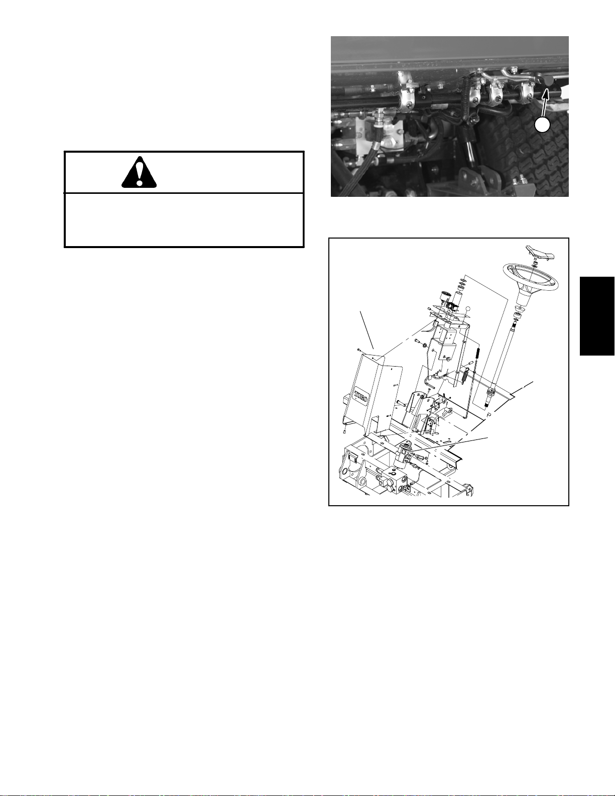
Procedure for Steering Circuit Relief Pressure Test
1. Make sure hydraulic oil is at normal operating temperatureby operatingthe machine for approximately 10
minutes. Make sure the hydraulic tank is full.
2. Park machine on a level surface with the cutting
decks lowered and off. Make sure engine is off and the
parking brake is applied.
CAUTION
1
Prevent personal injury and/or damage to equipment. Read all WARNINGS, CAUTIONS and Precautions for Hydraulic Testing at the beginning
of this section.
3. Connect a 5000 PSI (350 bar) pressure gauge onto
steering pressure test port.
4. Start the engine and move throttle to full engine
speed (2870 RPM).
IMPORTANT: Hold steering wheel at full lock only
long enough to get a system pressure reading.
Holding the steering wheel against the stop for an
extended period can damage the steering valve.
5. Turn steering all the way in one direction and momentarily hold the steering wheel against resistance.
GAUGEREADINGTOBE1300 to 1400 PSI (90 to
96 bar).
6. Stop the engine and record test results.
7. If pressure is incorrect, inspect steering relief valve
incontrol valve (Fig. 40). Ifreliefvalveisoperatingproperly and if lift/lower problems also exist, gear pump
shouldbe suspected ofwearandinefficiency.Ifsteering
wheel continues to turn at end of cylinder travel (with
lower than normal effort), steering cylinder or steering
valve should be suspected of wear or damage.
Figure 39
1. Steering circuit pressure test port
1
2
Figure 40
1. Steering tower 2. Steering relief valve
System
Hydraulic
8. When testing is completed, disconnect pressure
gauge from test port.
Groundsmaster 4000--D Hydraulic SystemPage 4 -- 51
Page 86
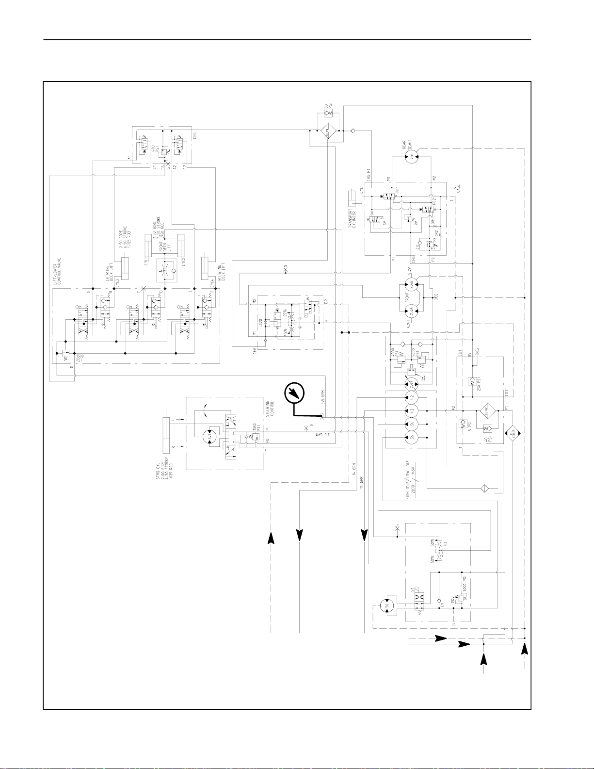
Lift/Lower Circuit Relief Pressure (Using Pressure Gauge)
COUNTERBALANCE
MANIFOLD
4WD
MANIFOLD
PRESSURE
GAUGE
FROM PTO MANIFOLDS
TO PTO (MOW) CIRCUIT
TRACTION
MANIFOLD
FILTER
MANIFOLD
MANIFOLD
FAN DRIVE
TO PTO (MOW) CIRCUIT
M1 M2 ST L
P1 P2T
FROM DECK MOTORS
FROM FRONT PTO MANIFOLD
CIRCUIT
MANIFOLD
FROM RH PTO
FROM RH PTO
Groundsmaster 4000--DHydraulic System Page 4 -- 52
Page 87

Procedure for Lift/Lower Circuit Relief Pressure
Test
NOTE: Before attempting to check or adjust lift pres-
sure, make sure that counterbalance pressure is correctly adjusted.
1. Make sure hydraulic oil is at normal operating temperatureby operatingthe machine for approximately 10
minutes. Make sure the hydraulic tank is full.
2. Park machine on a level surface with the cutting
decks lowered and off. Make sure engine is off and the
parking brake is applied.
CAUTION
Prevent personal injury and/or damage to equipment. Read all WARNINGS, CAUTIONS and Precautions for Hydraulic Testing at the beginning
of this section.
3. Raiseseatto gain access tolift circuit test port at the
fan drive manifold (Fig. 41). Connect a 5,000 PSI (345
bar) gauge with hydraulic hose attached to test port.
Route gauge hose to allow seat to be safely lowered.
4. Sit on the seat and start the engine. Move throttle to
full speed (2870 RPM).
3
4
1. Fan drive manifold
2. Lift circuit test port
2
Figure 41
3. Lift control valve
4. Relief valve
1
2
System
3
4
5
Hydraulic
5. While sitting on the seat, pull lift lever back to raise
thecutting decks. Momentarily hold the lever with the lift
cylinder at full extension while looking at the gauge.
GAUGEREADING TOBE 1500 to 1600 PSI (104 to
110 bar).
6. Stop the engine and record test results.
7. Ifpressure is too high, adjust reliefvalveinliftcontrol
valve by rotating counterclockwise (Figure 42). If pressure is too low, check for restriction in pump intake line.
Check the lift cylinder for internal leakage. If cylinder is
notleaking,adjustthe relief valve by rotatingclockwise.
Repeatsteps 4 through6 after makinga relief valve adjustment. If pressure is still too low, pump or lift cylinder(s) should be suspected of wear, damage or
inefficiency.
8. When testing is completed, disconnect pressure
gauge from test port.
Figure 42
1. Control valve assembly
2. Relief valve assembly
3. Washers
1
4. Spring
5. Poppet
Groundsmaster 4000--D Hydraulic SystemPage 4 -- 53
Page 88

Steering and Lift/Lower Gear Pump Flow (Using Tester with Pressure Gauges and Flow
Meter)
COUNTERBALANCE
MANIFOLD
4WD
MANIFOLD
FROM PTO MANIFOLDS
TO PTO (MOW) CIRCUIT
TRACTION
MANIFOLD
FILTER
MANIFOLD
TESTER
MANIFOLD
FAN DRIVE
TO PTO (MOW) CIRCUIT
FROM DECK MOTORS
FROM FRONT PTO MANIFOLD
Groundsmaster 4000--DHydraulic System Page 4 -- 54
MANIFOLD
FROM RH PTO
CIRCUIT
FROM RH PTO
Page 89

Procedure for Steering and Lift/Lower Gear Pump
Flow Test
1. Make sure hydraulic oil is at normal operating temperatureby operatingthe machine for approximately 10
minutes. Make sure the hydraulic tank is full.
2
3
2. Park machine on a level surface with the cutting
decks lowered and off. Make sure engine is off and the
parking brake is applied.
CAUTION
Prevent personal injury and/or damage to equipment. Read all WARNINGS, CAUTIONS and Precautions for Hydraulic Testing at the beginning
of this section.
IMPORTANT: Make sure that the oil flow indicator
arrow on the flow gauge is showing that the oil will
flow from the pump section, through the tester and
into the hydraulic hose.
3. With the engine off and cutting decks lowered, disconnect the hydraulic hose from the 90
thirdgear pumpsection which supplies the steering and
lift/lower circuits (Fig. 43).
4. Installtester in seriesbetweenthefittingand the disconnectedhose. Make sure the tester flow control valve
is OPEN.
o
fitting in the
4
1. Gear pump
2. Fan drive manifold
1
Figure 43
3. Steering/lift hose
4. 90
o
fitting
System
Hydraulic
IMPORTANT: The pump is a positive displacement
type. If pump flow is completely restricted or
stopped, damage to the pump, tester or other components could occur.
5. Starttheengine andmovethrottle tofullspeed(2870
RPM). DO NOT engage the cutting decks.
6. While watching pressure gauges, slowly close flow
control valve until 1000 PSI (69 bar) is obtained on
gauge. Verifyengine speed continues to be 2870 RPM.
GAUGE READING TO BE: Flow approximately 7
GPM (26.3 LPM) at 1000 PSI (69 bar).
7. Stop engine and record test results.
8. If a pressure of 1000 PSI (69 bar) could not be obtained or flow is lower than 6GPM(22.3LPM)(85% of
expectedflow),check for restriction in pump intakeline.
Ifintakeline is not restricted, consider thatgear pump is
worn or damaged.
9. Whentesting is complete, remove tester and reconnect hose to pump fitting.
Groundsmaster 4000--D Hydraulic SystemPage 4 -- 55
Page 90

Engine Cooling Fan Circuit (Using Pressure Gauge and Phototac)
COUNTERBALANCE
MANIFOLD
4WD
MANIFOLD
MANIFOLD
TRACTION
FROM PTO MANIFOLDS
TO PTO (MOW) CIRCUIT
TO PTO (MOW) CIRCUIT
FROM DECK MOTORS
FROM FRONT PTO MANIFOLD
MANIFOLD
FAN DRIVE
FILTER
MANIFOLD
CIRCUIT
MANIFOLD
FROM RH PTO
FROM RH PTO
Groundsmaster 4000--DHydraulic System Page 4 -- 56
Page 91

Procedure for Engine Cooling Fan Circuit Test
1. Make sure hydraulic oil is at normal operating temperatureby operatingthe machine for approximately 10
minutes. Make sure the hydraulic tank is full.
2. Park machine on a level surface with the cutting
decks lowered and off. Make sure engine is off and the
parking brake is applied. Raise and support hood.
CAUTION
Prevent personal injury and/or damage to equipment. Read all WARNINGS, CAUTIONS and Precautions for Hydraulic Testing at the beginning
of this section.
3. Raise seat to gain access to cooling fan circuit test
port at the fan drive manifold (Fig. 44). Connect a 5,000
PSI(345 bar)gaugewithhydraulic hoseattachedtotest
port on top of manifold.
2
1
1. Fan drive manifold
2. PRV solenoid
3
Figure 44
3. Test port
4. Start the engine. Move throttle to full speed (2870
RPM).
5. While monitoring the pressure gauge and using a
phototac to identify the cooling fan speed, disconnect
the wire harness connector (white/green and black
wires)fromthePRVsolenoidonfandrivemanifold.Both
fan speed and pressure should increase and stabilize
after the solenoid is disconnected.
PRESSURE GAUGE READING TO BE approxi-
mately 3000 PSI (207 bar).
PHOTOTAC READING TO BE: fan speed approxi-
mately 2800 RPM.
6. Stop engine and record test results.
7. If pressure rises to approximately 3000 PSI (207
bar) but fan speed is low, consider that the fan motor is
worn or damaged. If pressure and fan speed are both
low, consider that the gear pump is worn or damaged
(see Engine Cooling Circuit Gear Pump Flow Test).
NOTE: Ifpressureandfanspeed are bothlowand gear
pumpflow proves tobec orrect, suspect thatsealsinfan
drivemanifold are leaking or faulty(see Fan Drive Manifold Service in the Service and Repairs section of this
chapter).
System
Hydraulic
8. When testing is complete, remove pressure gauge
and reconnect wire harness to PRV solenoid.
Groundsmaster 4000--D Hydraulic SystemPage 4 -- 57
Page 92

Engine Cooling Fan Circuit Gear Pump Flow (Using Tester with Pressure Gauges and
Flow Meter)
COUNTERBALANCE
MANIFOLD
4WD
MANIFOLD
FROM PTO MANIFOLDS
TO PTO (MOW) CIRCUIT
TRACTION
MANIFOLD
FILTER
MANIFOLD
TESTER
MANIFOLD
FAN DRIVE
TO PTO (MOW) CIRCUIT
FROM DECK MOTORS
FROM FRONT PTO MANIFOLD
Groundsmaster 4000--DHydraulic System Page 4 -- 58
MANIFOLD
FROM RH PTO
CIRCUIT
FROM RH PTO
Page 93

Procedure for Engine Cooling Fan Circuit Gear
Pump Flow Test
1. Make sure hydraulic oil is at normal operating temperatureby operatingthe machine for approximately 10
minutes. Make sure the hydraulic tank is full.
2. Park machine on a level surface with the cutting
decks lowered and off. Make sure engine is off and the
parking brake is applied.
CAUTION
2
4
1
Prevent personal injury and/or damage to equipment. Read all WARNINGS, CAUTIONS and Precautions for Hydraulic Testing at the beginning
of this section.
IMPORTANT: Make sure that the oil flow indicator
arrow on the flow gauge is showing that the oil will
flow from the pump section, through the tester and
into the hydraulic hose.
3. With the engine off and cutting decks lowered, dis-
o
connectthe hydraulic hose from the90
fittingin the last
gear pump section which supplies the engine cooling
circuit (Fig. 43).
4. Installtester in seriesbetweenthefittingand the disconnectedhose. Make sure the tester flow control valve
is OPEN.
IMPORTANT: The pump is a positive displacement
type. If pump flow is completely restricted or
stopped, damage to the pump, tester or other components could occur.
5. Starttheengine andmovethrottle tofullspeed(2870
RPM). DO NOT engage the cutting decks.
1. Gear pump
2. Fan drive manifold
3
Figure 45
3. Engine cooling hose
o
4. 90
fitting
System
Hydraulic
6. Whilewatchingtesterpressuregauges, slowlyclose
flow control valve until 1000 PSI (69 bar) is obtained on
gauge. Verifyengine speed continues to be 2870 RPM.
GAUGE READING TO BE: Flow approximately 7
GPM (26.3 LPM) at 1000 PSI (69 bar).
7. Stop engine and record test results.
8. If a pressure of 1000 PSI (69 bar) could not be obtained or flow is lower than 6GPM(22.3LPM)(85% of
expectedflow),check for restriction in pump intakeline.
Ifintakeline is not restricted, consider thatgear pump is
worn or damaged.
9. Whentesting is complete, remove tester and reconnect hose to pump fitting.
Groundsmaster 4000--D Hydraulic SystemPage 4 -- 59
Page 94

Adjustments
Adjust Front Cutting Deck Lift Flow Control
The front cutting deck lift circuit is equipped with an adjustable flow control valve used to adjust the rate at
which the front cutting deck lowers. Adjust flow control
valve as follows:
1. Runmachinetogethydraulicoilatoperatingtemperatures.Parkmachine on a level surface, shut engineoff
and lower cutting decks to the ground.
2. Locateflowcontrolvalveunderfrontofmachine(Fig.
46).
3. Loosen set screw on valve and rotate valve clockwise to slow down drop rate of front cutting deck.
4. Verify adjustment by raising and lowering cutting
deck several times. Readjust as required.
5. After desired drop rate is attained, tighten set screw
on flow control valve to secure adjustment.
1
2
1
Figure 46
1. Front lift cylinder 2. Flow control valve
Groundsmaster 4000--DHydraulic System Page 4 -- 60
Page 95

Service and Repairs
General Precautions for Removing and Installing Hydraulic System Components
Before Repair or Replacement of Components
1. Before removing any parts from the hydraulic system, park machine on a level surface, apply parking
brake, lower cutting decks or attachments and stop engine. Remove key from the ignition switch.
2. Clean machine before disconnecting, removing or
disassembling any hydraulic components. Make sure
hydraulic components, hoses connections and fittings
are cleaned thoroughly. Always keep in mind the need
for cleanliness when working on hydraulic equipment.
CAUTION
Operate all hydraulic controls to relieve system
pressure and avoid injury from pressurized hydraulic oil.
3. Putcapsor plugsonanyhydrauliclines, hydraulicfittings and components left open or exposed to prevent
contamination.
4. Put labels on disconnected hydraulic lines and
hosesforproperinstallationafterrepairs arecompleted.
5. Note the position of hydraulic fittings (especially elbow fittings) on hydraulic components before removal.
Markpartsifnecessarytomake suretheywillbealigned
properly when installing hydraulic hoses and tubes.
After Repair or Replacement of Components
1. Checkoillevelinthehydraulic reservoirandadd correct oil if necessary. Drain and refill hydraulic system
reservoir and change oil filter if component failure was
severe or system is contaminated (see Flush Hydraulic
System in this section).
2. Lubricate O--rings and seals with clean hydraulic oil
before installing hydraulic components.
3. Make sure caps or plugs are removed from the hydraulic tubes, hydraulic fittings and components before
reconnecting.
4. Use proper tightening methods when installing hydraulichoses and fittings (seeHydraulic Fitting Installation in the General Information section of this chapter).
5. After repairs, check control linkages or cables for
proper adjustment, binding or broken parts.
6. After disconnecting or replacing any hydraulic components, operate machine functions slowly until air is
outof system(seeChargeHydraulic System inthissection).
7. Checkforhydraulicoilleaks.Shutoffengineandcorrectleaksifnecessary.Checkoillevelin hydraulicreservoir and add correct oil if necessary.
System
Hydraulic
Check Hydraulic Lines and Hoses
IMPORTANT: Checkhydraulic lines andhoses daily
WARNING
Keep body and hands away from pin hole leaks
or nozzles that eject hydraulic fluid under high
pressure. Use paper or cardboard, not hands, to
search for leaks. Hydraulic fluid escaping under
pressure can have sufficient force to penetrate
the skin and cause serious injury. If fluid is injected into the skin, it must be surgically removed within a few hours by a doctor familiar
withthistypeof injury.Gangrenemayresultfrom
such an injury.
Groundsmaster 4000--D Hydraulic SystemPage 4 -- 61
for leaks, kinked lines, loose mounting supports,
wear,loose fittings or any hose deterioration. Make
all necessary repairs before operating.
Page 96

Flush Hydraulic System
IMPORTANT: Flush the hydraulic system any time
thereis a severe component failure orthe system is
contaminated (oil appears milky, black or contains
metal particles).
1. Park machine on a level surface. Lower cutting
decks to the ground, stop engine and apply parking
brake. Remove key from the ignition switch.
CAUTION
Operate all hydraulic controls to relieve system
pressure and avoid injury from pressurized hydraulic oil.
IMPORTANT: Make sure to clean around any hydraulic connections that will be disconnected for
draining.
2. Drain hydraulic reservoir.
3. Drain hydraulic system. Drain all hoses, tubes and
components while the system is warm.
4. Change and replace both hydraulic oil filters.
9. Turn ignition key switch and engage starter for ten
(10) seconds to prime hydraulic pumps. Repeat this
step again.
10.Connect electrical connector to engine runsolenoid.
11.Start engine and let it idle at low speed (1450 RPM)
for a minimum of two (2) minutes. Increase engine
speed to high idle (2870 RPM) for minimum of one (1)
minute under no load.
12.Raise and lower cutting decks several times. Turn
steering wheel fully left and right several times.
13.Shut off engine and check for hydraulic oil leaks.
Check oil level in hydraulic reservoir and add correct
amount of oil if necessary.
14.Operate machine for two(2) hours under normal operating conditions.
15.Check condition of hydraulic oil. If the new fluid
shows any signs of contamination, repeat steps 1
through 14 again until oil is clean.
16.Assume normaloperation and followrecommended
maintenance intervals.
5. Inspectand cleanhydraulicreservoir (see Hydraulic
Reservoir Inspection in this section).
6. Connect all hydraulic hoses, lines and components
that were disconnected while draining system.
NOTE: Useonlyhydraulicfluids specifiedinthe Operator’s Manual. Other fluids may cause system damage.
7. Fill hydraulic reservoir with new hydraulic fluid.
8. Disconnectelectrical connector from engine run solenoid.
Groundsmaster 4000--DHydraulic System Page 4 -- 62
Page 97

Charge Hydraulic System
NOTE: Wheninitially starting the hydraulic systemwith
newor rebuilt components such as motors, pumps or lift
cylinders, it is important that the hydraulic system be
charged properly. Air must be purged from the system
to reduce the chance of component damage.
IMPORTANT: Change hydraulic oil filters whenever
hydraulic components are repaired or replaced.
1. Park machine on a level surface. Lower cutting
decks, stop engine and apply parking brake. Remove
key from the ignition switch.
2. Makesure all hydraulic connections, lines and components are secured tightly.
3. Ifcomponentfailurewassevereorthesystemiscontaminated, flush and refill hydraulic system and tank
(see Flush Hydraulic System in this section).
4. Makesure hydraulic reservoir is full. Add correct hydraulic oil if necessary.
5. Check control rod to the piston ( traction) pump for
proper adjustment, binding or broken parts.
11.After the hydraulicsystem starts to showsigns of fill,
actuate lift control lever until the lift cylinder rod moves
in and out several times. If the cylinder rod does not
moveafter10 to 15 seconds, or the pump e mits abnormal sounds, shut the engine off immediately and determine cause or problem. Inspect for the following:
A. Loose filter or suction lines.
B. Blocked suction line.
C. Faulty charge relief valve.
D. Faulty gear pump.
12.If cylinder does move in 10 to 15 seconds, proceed
to step 13.
13.Operatethetractionpedalin theforward andreverse
directions. The wheels off the ground should rotate in
the proper direction.
A. If the wheels rotate in the wrong direction, stop
engine and check for proper hose connections at
traction pump and motors. Correct as needed.
System
Hydraulic
6. Disconnect engine run solenoid lead to prevent the
engine from starting.
7. Make sure traction pedal and lift control lever are in
the neutral position. Turn ignition key switch and engage starter for ten (10) seconds to prime the traction
and gear pumps. Repeat this step again.
8. Reconnect engine run solenoid lead.
WARNING
Beforejacking upthe machine,review andfollow
Jacking Instructions in Chapter 1 -- Safety.
9. Raise one front and one rear wheel off the ground
and place support blocks under the frame. Chock remaining wheels to prevent movement of the machine.
10.Make sure traction pedal and lift control lever are in
neutral. Start engine and run it at low idle (1450 rpm).
Thecharge pump should pick up oil andfillthehydraulic
system. If there is no indication of fill in thirty (30) seconds, stop the engine and determine the cause.
B. If the wheels rotate in the proper direction, stop
engine.
14.Adjust traction pedal to the neutral position.
15.Check operation of the traction interlock switch (see
Check Interlock System in Chapter 5 -- Electrical System).
16.Remove blocks from frame and lower machine. Remove chocks from remaining wheels.
17.If the piston (traction) pump or a traction motor was
replaced or rebuilt, run the machine so all wheels turn
slowly for ten (10) minutes.
18.Operate machine by gradually increasing its work
load to full over a ten (10) minute period.
19.Stop the machine. Check hydraulic reservoir and fill
ifnecessary.Checkhydrauliccomponents for leaksand
tighten any loose connections.
Groundsmaster 4000--D Hydraulic SystemPage 4 -- 63
Page 98

Hydraulic Reservoir
23
9
18
19
25
7
12
13
11
27
15
14
9
10
1
6
5
24
17
16
3
21
2
30 to 40 in--lb
(3.4 to 4.5 N--m)
(minimum)
4
8
20
31
28
30
22
26
RIGHT
FRONT
1. Hydraulic reservoir
2. Petcock
3. O--ring
4. Strap
5. Felt strap (2 used)
6. Bushing (2 used)
7. Bushing
8. Strap
9. Stand pipe (2 used)
10. Hose clamp (2 used)
11. Screen filter
29
Figure 47
12. Dipstick
13. O--ring
14. Reservoir cap
15. Suction hose
16. Tank strainer
17. Hose clamp
18. Hose
19. Hose clamp
20. Cap screw
21. Socket head screw (3 used)
NOTE: HYDRAULIC COMPONENTS
ATTACHED TO FRONT FRAME ARE
NOT SHOWN IN ILLUSTRATION
22. Lock nut (3 used)
23. Hose
24. Hose
25. Elbow fitting
26. Flange nut
27. O--ring
28. Flat washer (4 used)
29. Front frame
30. Flange nut (4 used)
31. Cap screw (4 used)
Groundsmaster 4000--DHydraulic System Page 4 -- 64
Page 99

NOTE: The front frame needs to be lowered from the
main frame to allow clearance to remove the hydraulic
reservoir from the machine.
Removal (Fig. 47)
1. Park machine on a level surface, lower cutting
decks, stop engine, apply parking brake and remove
key from the ignition switch.
2. Remove front cutting deck (see Front Cutting Deck
Removal in the Service and Repairs section of Chapter
8 -- Cutting Decks).
Inspection
1. Clean hydraulic reservoir and suction strainer with
solvent.
2. Inspect reservoir for leaks, cracks or other damage.
Installation (Fig. 47)
1. Using a wrench, turn tank strainer into port at least
1--1/2 to 2 full turns beyond finger tight.
2. Position reservoir to machine.
3. Read the General Precautions for Removing and
Installing Hydraulic System Components at the beginning of the Service and Repairs section of this chapter.
4. Drain reservoir into a suitable container.
5. Disconnect hydraulic hoses from reservoir. Label
disconnected hydraulic lines for proper installation.
6. Removestraps(items 4 and 8)that secure reservoir
tofront frame. Remove felt straps(item3)frombetween
straps and reservoir.
7. To allow front frame to be lowered for reservoir removal, remove hydraulic tubes that connect hydraulic
components on front frame (wheel motors, front deck
PTO manifold and traction manifold) to components on
main frame. Put caps or plugs on open hydraulic lines
and fittings.
8. Chockrearwheelstopreventthemachinefrommoving. Use jack or hoist to raise front of machine and support machine with jackstands.
9. Support front frame to prevent it from moving.
3. Carefully raise front frame assembly to main frame.
Align frame mounting holes and support front frame to
prevent it from moving.
4. Secure front frame to main frame with cap screws
(item 35), flat washers (item 28) and flange nuts (item
30).
5. Lower machine to ground.
6. Position felt straps (item 3) between straps and reservoir.Securereservoir to front frame with straps (items
4 and 8).
7. Removecaps and plugs from hydraulic lines and fittings that were placed during the removal process. Using labels placed during removal, connect hydraulic
hoses and tubes to fittings on reservoir, wheel motors
and hydraulic manifolds (see Hydraulic Hose and Tube
Installation in the General Information section of this
chapter).
8. Install front cutting deck (see Front Cutting Deck
Installation in the Service and Repairs section of Chapter 8 -- Cutting Decks).
System
Hydraulic
10.Remove capscrews(item35), flatwashers(item 28)
9. Fill reservoir with new hydraulic fluid to proper level.
andflange nuts (item 30) thatsecurefrontframe to main
frame.
10.Properly fillhydraulic system (see Charge Hydraulic
System in this section).
11.Carefully lower front frame assembly to allow clearanceforreservoirremoval.Once lowered, support front
frame to prevent it from shifting.
11.Stop engine and check for hydraulic oilleaks.Check
hydraulic reservoir oil level.
12.Carefully remove hydraulic reservoir from machine.
Groundsmaster 4000--D Hydraulic SystemPage 4 -- 65
Page 100

Hydraulic Oil Cooler
RIGHT
FRONT
8
9
4
3
10
5
6
7
8
9
10
2
1
11
12
13
14
15
16
12
17
18
1. Radiator
2. RH radiator support
3. Top radiator support
4. Knob (2 used)
5. Oil cooler bracket
6. Retaining ring (2 used)
Figure 48
7. Carriage screw (2 used)
8. O--ring
o
9. 90
10. O--ring
11. Cap screw (2 used)
12. Lock washer (6 used)
hydraulic fitting (2 used)
12 ft--lb
(16 N--m)
13. Oil cooler
14. Flange nut (2 used)
15. Cap screw(2 used)
16. Oil cooler mount plate (2 used)
17. Cap screw (4 used)
18. LH radiator support
Groundsmaster 4000--DHydraulic System Page 4 -- 66
 Loading...