

Page 1
PART NO. 02097SL (Rev. F)
Service Manual
(Model 30410)
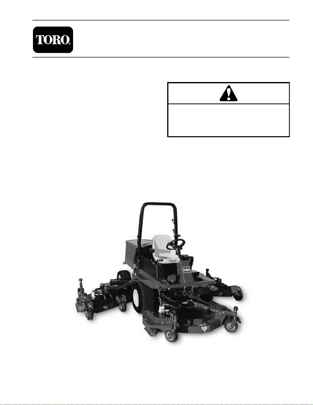
Groundsmaster
Preface
The purpose of this publication is to provide the service
technician with information for troubleshooting, testing,
and repair of major systems and components on the
Groundsmaster 4000--D.
REFER TO THE TRACTION UNIT AND CUTTING
UNIT OPERATOR’S MANUALS FOR OPERATING,
MAINTENANCE, AND ADJUSTMENT INSTRUCTIONS. Space is provided in Chapter 2 of this book to
insert the Operator’s Manuals and Parts Catalogs for
your machine. Replacement Operator’s Manuals and
Parts Catalogs are available on the internet at www.Toro.com.
TheToroCompanyreserves therighttochangeproduct
specifications or this publication without notice.
R
4000--D
This safety symbol means DANGER, WARNING,
or CAUTION, PERSONAL SAFETY INSTRUCTION. When you see this symbol, carefully read
the instructions that follow. Failure to obey the
instructions may result in personal injury.
NOTE: ANOTE will give generalinformation about the
correct operation, maintenance, service, testing, or repair of the machine.
IMPORTANT: The IMPORTANT notice will give importantinstructionswhichmustbefollowed toprevent damage to systems or components on the
machine.
E The Toro Company -- 2002, 2003, 2004, 2006, 2007, 2012
Page 2

This page is intentionally blank.
Groundsmaster 4000−D
Page 3

Table Of Contents
Chapter 1 − Safety
General Safety Instructions 1 − 2. . . . . . . . . . . . . . . . . .
Jacking Instructions 1 − 4. . . . . . . . . . . . . . . . . . . . . . . . .
Safety and Instruction Decals 1 − 5. . . . . . . . . . . . . . . .
Chapter 2 − Product Records and Maintenance
Product Records 2 − 1. . . . . . . . . . . . . . . . . . . . . . . . . . .
Maintenance 2 − 1. . . . . . . . . . . . . . . . . . . . . . . . . . . . . . .
Equivalents and Conversions 2 − 2. . . . . . . . . . . . . . . .
Torque Specifications 2 − 3. . . . . . . . . . . . . . . . . . . . . . .
Chapter 3 − Kubota Diesel Engine
General Information 3 − 2. . . . . . . . . . . . . . . . . . . . . . . .
Specifications 3 − 3. . . . . . . . . . . . . . . . . . . . . . . . . . . . . .
Adjustments 3 − 4. . . . . . . . . . . . . . . . . . . . . . . . . . . . . . .
Service and Repairs 3 − 6. . . . . . . . . . . . . . . . . . . . . . . .
KUBOTA WORKSHOP MANUAL, DIESEL ENGINE,
V2003−T SERIES
Chapter 4 − Hydraulic System
Specifications 4 − 2. . . . . . . . . . . . . . . . . . . . . . . . . . . . . .
General Information 4 − 3. . . . . . . . . . . . . . . . . . . . . . . .
Hydraulic Schematic 4 − 6. . . . . . . . . . . . . . . . . . . . . . . .
Hydraulic Flow Diagrams 4 − 8. . . . . . . . . . . . . . . . . . . .
Special Tools 4 − 18. . . . . . . . . . . . . . . . . . . . . . . . . . . . .
Troubleshooting 4 − 20. . . . . . . . . . . . . . . . . . . . . . . . . . .
Testing 4 − 23. . . . . . . . . . . . . . . . . . . . . . . . . . . . . . . . . . .
Adjustments 4 − 48. . . . . . . . . . . . . . . . . . . . . . . . . . . . . .
Service and Repairs 4 − 49. . . . . . . . . . . . . . . . . . . . . . .
Chapter 5 − Electrical System
Electrical Schematic, Circuit Diagrams, and
Wire Harness Drawings 5 − 2. . . . . . . . . . . . . . . . . . . .
Special Tools 5 − 3. . . . . . . . . . . . . . . . . . . . . . . . . . . . . .
Troubleshooting 5 − 4. . . . . . . . . . . . . . . . . . . . . . . . . . . .
Electrical System Quick Checks 5 − 7. . . . . . . . . . . . . .
Component Testing 5 − 8. . . . . . . . . . . . . . . . . . . . . . . . .
Service and Repairs 5 − 28. . . . . . . . . . . . . . . . . . . . . . .
Chapter 6 − Axles, Planetaries, and Brakes
Specifications 6 − 2. . . . . . . . . . . . . . . . . . . . . . . . . . . . . .
Adjustments 6 − 3. . . . . . . . . . . . . . . . . . . . . . . . . . . . . . .
Service and Repairs 6 − 4. . . . . . . . . . . . . . . . . . . . . . . .
Chapter 7 − Chassis
Service and Repairs 7 − 2. . . . . . . . . . . . . . . . . . . . . . . .
Chapter 8 − Cutting Units
Specifications 8 − 2. . . . . . . . . . . . . . . . . . . . . . . . . . . . . .
Troubleshooting 8 − 3. . . . . . . . . . . . . . . . . . . . . . . . . . . .
Adjustments 8 − 4. . . . . . . . . . . . . . . . . . . . . . . . . . . . . . .
Service and Repairs 8 − 6. . . . . . . . . . . . . . . . . . . . . . . .
Chapter 9 − Electrical Diagrams
Electrical Schematic 9 − 3. . . . . . . . . . . . . . . . . . . . . . . .
Circuit Diagrams 9 − 5. . . . . . . . . . . . . . . . . . . . . . . . . . .
Wire Harness Drawings 9 − 9. . . . . . . . . . . . . . . . . . . . .
SafetyProduct Records
and Maintenance
Kubota
Diesel Engine
System
Hydraulic
System
Electrical
Groundsmaster 4000−D
Rev. E
and Brakes
Axles, Planetaries,
Cutting Units Chassis
Electrical
Diagrams
Page 4

This page is intentionally blank.
Groundsmaster 4000−D
Page 5

Table of Contents
Chapter 1
Safety
Safety
GENERAL SAFETY INSTRUCTIONS 2. . . . . . . . . . . .
Before Operating 2. . . . . . . . . . . . . . . . . . . . . . . . . . . .
While Operating 2. . . . . . . . . . . . . . . . . . . . . . . . . . . .
Maintenance and Service 3. . . . . . . . . . . . . . . . . . . .
JACKING INSTRUCTIONS 4. . . . . . . . . . . . . . . . . . . . .
SAFETY AND INSTRUCTION DECALS 5. . . . . . . . . .
Groundsmaster 4000−D
Page 1 − 1
Safety
Page 6
General Safety Instructions
The GROUNDSMASTER 4000-D was tested and certified by T ORO for compliance with the B71.4-1999 specifications of the American National Standards Institute.
Although hazard control and accident prevention partially are dependent upon the design and configuration
of the machine, these factors are also dependent upon
the awareness, concern, and proper training of the personnel involved in the operation, transport, maintenance, and storage of the machine. Improper use or
maintenance of the machine can result in injury or
Before Operating
1. Read and understand the contents of the Operator’s
Manual before starting and operating the machine. Become familiar with the controls and know how to stop the
machine and engine quickly . A replacement Operator’s
Manual is available on the Internet at www.Toro.com or
by sending the complete model and serial number to:
The Toro Company
Attn. Technical Publications
8111 Lyndale Avenue South
Bloomington, Minnesota 55420−1196
2. Keep all shields, safety devices, and decals in place.
If a shield, safety device, or decal is defective, illegible
or damaged, repair or replace it before operating the
machine. Also tighten any loose nuts, bolts or screws to
ensure machine is in safe operating condition.
death. To reduce the potential for injury or death, comply
with the following safety instructions.
WARNING
To reduce the potential for injury or death,
comply with the following safety instructions.
3. Assure interlock switches are adjusted correctly so
engine cannot be started unless traction pedal is in
NEUTRAL and cutting units are DISENGAGED.
4. Since diesel fuel is highly flammable, handle it carefully:
A. Use an approved fuel container.
B. Do not remove fuel tank cap while engine is hot or
running.
C. Do not smoke while handling fuel.
D. Fill fuel tank outdoors and only to within an inch of
the top of the tank, not the filler neck. Do not overfill.
E. Wipe up any spilled fuel.
While Operating
1. Sit on the seat when starting and operating the machine.
2. Before starting the engine:
A. Engage the parking brake.
B. Make sure traction pedal is in neutral and the
PTO switch is OFF (disengaged).
C. After engine is started, release parking brake and
keep foot off traction pedal. Machine must not move.
If movement is evident, the traction pedal linkage is
adjusted incorrectly; therefore, shut engine off and
adjust until machine does not move when traction
pedal is released.
3. Do not run engine in a confined area without ade-
quate ventilation. Exhaust fumes are hazardous and
could possibly be deadly.
4. Do not touch engine, muffler or exhaust pipe while
engine is running or soon after it is stopped. These areas
could be hot enough to cause burns.
Safety
Page 1 − 2
5. Before getting off the seat:
A. Ensure that traction pedal is in neutral.
B. Set parking brake.
C. Disengage cutting units and wait for blades to
stop.
D. Stop engine and remove key from switch.
E. Toro recommends that anytime the machine is
parked (short or long term), the cutting units should
be lowered to the ground. This relieves pressure
from the lift circuit and eliminates the risk of cutting
units accidentally lowering to the ground.
F. Do not park on slopes unless wheels are chocked
or blocked.
Groundsmaster 4000−D
Page 7

Maintenance and Service
1. Before servicing or making adjustments, lower
decks, stop engine, set parking brake, and remove key
from the switch.
2. Make sure machine is in safe operating condition by
keeping all nuts, bolts and screws tight.
3. Never store the machine or fuel container inside
where there is an open flame, such as near a water heater or furnace.
4. Make sure all hydraulic line connectors are tight, and
all hydraulic hoses and lines are in good condition before applying pressure to the system.
5. Keep body and hands away from pin hole leaks in hydraulic lines t h a t e j e c t h i gh p r essure hydraulic fluid. Use
cardboard or paper to find hydraulic leaks. Hydraulic
fluid escaping under pressure can penetrate skin and
cause injury. Fluid accidentally injected into the skin
must be surgically removed within a few hours by a doctor familiar with this form of injury or gangrene may result.
6. Before disconnecting or performing any work on the
hydraulic system, all pressure in system must be relieved by stopping engine and lowering cutting units to
the ground.
10.Do not overspeed the engine by changing governor
setting. To assure safety and accuracy, check maximum
engine speed.
11.Shut engine off before checking or adding oil to the
crankcase.
12.Disconnect battery before servicing the machine.
Disconnect negative cable first and positive cable last.
If battery voltage is required for troubleshooting or test
procedures, temporarily connect the battery. Reconnect
positive cable first and negative cable last.
13.Battery acid is poisonous and can cause burns.
Avoid cont a c t with skin, eyes, and clothing. Protect your
face, eyes, and clothing when working with a battery.
14.Battery gases can explode. Keep cigarettes, sparks,
and flames away from the battery.
15.At the time of manufacture, the machine conformed
to the safety standards for riding mowers. To assure optimum performance and continued safety certification of
the machine, use genuine Toro replacement parts and
accessories. Replacement parts and accessories made
by other manufacturers may result in non-conformance
with the safety standards, and the warranty may be
voided.
Safety
7. If major repairs are ever needed or assistance is desired, contact an Authorized Toro Distributor.
8. To reduce potential fire hazard, keep engine area
free of excessive grease, grass, leaves and dirt. Clean
protective screen on machine frequently.
9. If engine must be running to perform maintenance or
an adjustment, keep hands, feet, clothing and other
parts of the body away from cutting units and other moving parts. Keep bystanders away.
16.When changing attachments, tires, or performing
other service, use correct blocks, hoists, and jacks.
Make sure machine is parked on a solid level surface
such as a concrete floor. Prior to raising the machine, remove any attachments that may interfere with the safe
and proper raising of the machine. Always chock or
block wheels. Use jack stands or solid wood blocks to
support the raised machine. If the machine is not properly supported by blocks or jack stands, the machine may
move or fall, which may result in personal injury (see
Jacking Instructions).
Groundsmaster 4000−D
Page 1 − 3
Safety
Page 8
Jacking Instructions
CAUTION
When changing attachments, tires, or performing other service, use correct blocks, hoists,
and jacks. Make sure machine is parked on a
solid level surface such as a concrete floor.
Prior to raising machine, remove any attachments that may interfere with the safe and proper raising of the machine. Always chock or block
wheels. Use jack stands or solid wood blocks to
support the raised machine. If the machine is
not properly supported by blocks or jack
stands, the machine may move or fall, which
may result in personal injury.
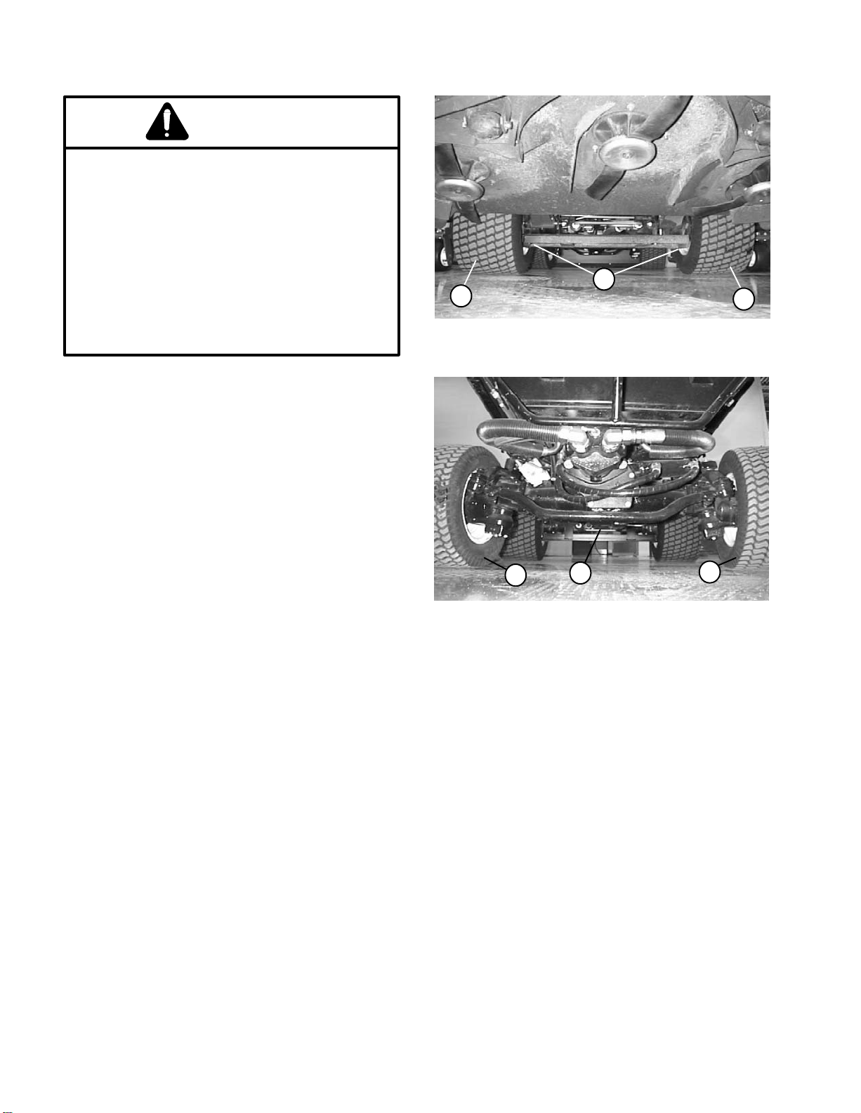
Jacking the Front End (Fig. 1)
1. Set parking brake and chock both rear tires to prevent the machine from moving.
2. Position jack securely under the frame, just to the inside of the front tire.
1
2
Figure 1
1. Frame jacking point 2. Front tire
2
3. Position jack stands or hardwood blocks under the
frame as close to the wheels as possible to support the
machine.
Jacking the Rear End (Fig. 2)
1. Place jack securely under the center of rear axle.
2. Chock both front tires. Jack rear of machine off the
ground.
3. Use jack stands or blocks under the axle to support
the machine.
2
1. Rear axle jacking point 2. Rear tire
1
Figure 2
2
Safety
Page 1 − 4
Groundsmaster 4000−D
Page 9

Safety and Instruction Decals
Numerous safety and instruction decals are affixed to the Groundsmaster 4000−D. If any decal becomes illegible or
damaged, install a new decal. Part numbers are listed in your Parts Catalog.
Safety
Groundsmaster 4000−D
Page 1 − 5
Safety
Page 10

This page is intentionally blank.
Safety
Page 1 − 6
Groundsmaster 4000−D
Page 11

Product Records and Maintenance
Table of Contents
Chapter 2
PRODUCT RECORDS 1. . . . . . . . . . . . . . . . . . . . . . . . .
MAINTENANCE 1. . . . . . . . . . . . . . . . . . . . . . . . . . . . . .
EQUIVALENTS AND CONVERSIONS 2. . . . . . . . . . .
Decimal and Millimeter Equivalents 2. . . . . . . . . . . .
U.S. to Metric Conversions 2. . . . . . . . . . . . . . . . . . .
TORQUE SPECIFICATIONS 3. . . . . . . . . . . . . . . . . . .
Fastener Identification 3. . . . . . . . . . . . . . . . . . . . . . .
Product Records
Insert Operator’s Manual and Parts Catalog for your
Groundsmaster 4000−D at the end of this chapter . Additionally, if any optional equipment or accessories have
been installed to your machine, insert the Installation Instructions, Operator’s Manuals and Parts Catalogs for
those options at the end of this chapter.
Maintenance
Maintenance procedures and recommended service intervals for the Groundsmaster 4000−D are covered in
the Operator’s Manual. Refer to that publication when
performing regular equipment maintenance.
Standard Torque for Dry, Zinc Plated, and
Steel Fasteners (Inch Series) 4. . . . . . . . . . . . . . .
Standard Torque for Dry, Zinc Plated, and
Steel Fasteners (Metric Fasteners) 5. . . . . . . . . .
Other Torque Specifications 6. . . . . . . . . . . . . . . . . .
Conversion Factors 6. . . . . . . . . . . . . . . . . . . . . . . . .
Product Records
and Maintenance
Groundsmaster 4000−D Page 2 − 1 Product Records and Maintenance
Rev. E
Page 12
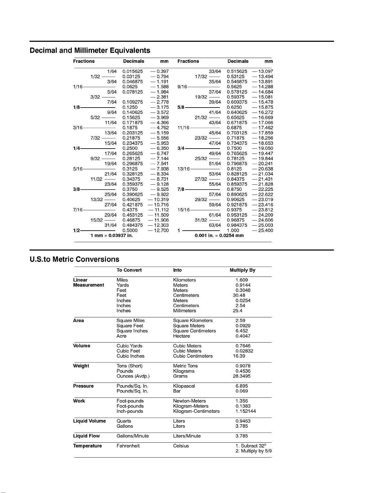
Equivalents and Conversions
0.09375
Rev. E
Groundsmaster 4000−DPage 2 − 2Product Records and Maintenance
Page 13
Torque Specifications
Recommended fastener torque values are listed in the
following tables. For critical applications, as determined
by Toro, either the recommended torque or a torque that
is unique to the application is clearly identified and specified in this Service Manual.
These Torque Specifications for the installation and
tightening of fasteners shall apply to all fasteners which
do not have a specific requirement identified in this Service Manual. The following factors shall be considered
when applying torque: cleanliness of the fastener, use
of a thread sealant (e.g. Loctite), degree of lubrication
on the fastener, presence of a prevailing torque feature,
hardness of the surface underneath the fastener’s head,
or similar condition which affects the installation.
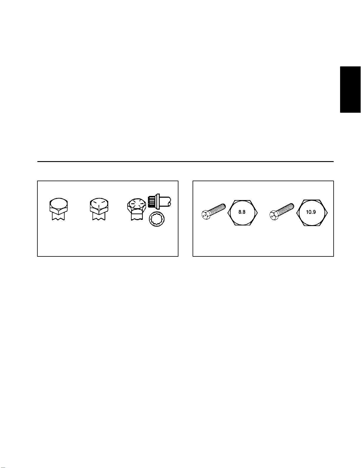
Fastener Identification
As noted in the following tables, torque values should be
reduced by 25% for lubricated fasteners to achieve
the similar stress as a dry fastener. Torque values may
also have to be reduced when the fastener is threaded
into aluminum or brass. The specific torque value
should be determined based on the aluminum or brass
material strength, fastener size, length of thread engagement, etc.
The standard method of verifying torque shall be performed by marking a line on the fastener (head or nut)
and mating part, then back off fastener 1/4 of a turn.
Measure the torque required to tighten the fastener until
the lines match up.
Product Records
and Maintenance
Grade 1 Grade 5 Grade 8
Inch Series Bolts and Screws
Figure 1
Class 8.8 Class 10.9
Metric Bolts and Screws
Figure 2
Groundsmaster 4000−D Page 2 − 3 Product Records and Maintenance
Page 14
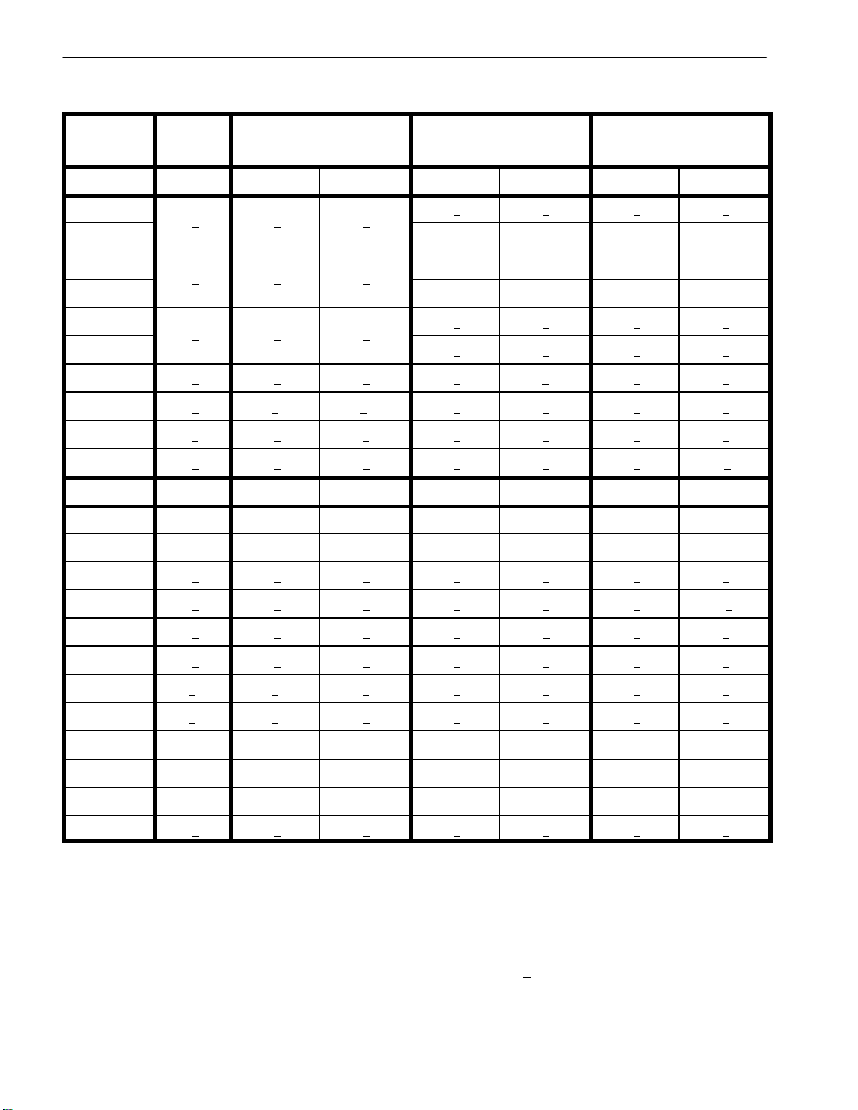
Standard Torque for Dry, Zinc Plated, and Steel Fasteners (Inch Series)
10 + 2
13 + 2
147 + 23
13 + 2
25 + 5
282 + 30
18 + 2
30 + 5
339 + 56
Grade 1, 5, &
Thread Size
# 6 − 32 UNC
# 6 − 40 UNF
# 8 − 32 UNC
# 8 − 36 UNF
# 10 − 24 UNC
# 10 − 32 UNF
1/4 − 20 UNC 48 + 7 53 + 7 599 + 79 100 + 10 1125 + 100 140 + 15 1580 + 170
1/4 − 28 UNF 53 + 7 65 + 10 734 + 113 115 + 10 1300 + 100 160 + 15 1800 + 170
5/16 − 18 UNC 115 + 15 105 + 17 1186 + 169 200 + 25 2250 + 280 300 + 30 3390 + 340
5/16 − 24 UNF 138 + 17 128 + 17 1446 + 192 225 + 25 2540 + 280 325 + 30 3670 + 340
3/8 − 16 UNC 16 + 2 16 + 2 22 + 3 30 + 3 41 + 4 43 + 4 58 + 5
8 with Thin
Height Nuts
in−lb in−lb N−cm in−lb N−cm in−lb N−cm
ft−lb ft−lb N−m ft−lb N−m ft−lb N−m
SAE Grade 1 Bolts, Screws, Studs, &
Sems with Regular Height Nuts
(SAE J995 Grade 2 or Stronger Nuts)
SAE Grade 5 Bolts, Screws, Studs, &
Sems with Regular Height Nuts
(SAE J995 Grade 2 or Stronger Nuts)
15 + 2 170 + 20 23 + 2 260 + 20
17 + 2 190 + 20 25 + 2 280 + 20
29 + 3 330 + 30 41 + 4 460 + 45
31 + 3 350 + 30 43 + 4 485 + 45
42 + 4 475 + 45 60 + 6 675 + 70
48 + 4 540 + 45 68 + 6 765 + 70
SAE Grade 8 Bolts, Screws, Studs, &
Sems with Regular Height Nuts
(SAE J995 Grade 5 or Stronger Nuts)
3/8 − 24 UNF 17 + 2 18 + 2 24 + 3 35 + 3 47 + 4 50 + 4 68 + 5
7/16 − 14 UNC 27 + 3 27 + 3 37 + 4 50 + 5 68 + 7 70 + 7 95 + 9
7/16 − 20 UNF 29 + 3 29 + 3 39 + 4 55 + 5 75 + 7 77 + 7 104 + 9
1/2 − 13 UNC 30 + 3 48 + 7 65 + 9 75 + 8 102 + 11 105 + 10 142 + 14
1/2 − 20 UNF 32 + 3 53 + 7 72 + 9 85 + 8 115 + 11 120 + 10 163 + 14
5/8 − 11 UNC 65 + 10 88 + 12 119 + 16 150 + 15 203 + 20 210 + 20 285 + 27
5/8 − 18 UNF 75 + 10 95 + 15 129 + 20 170 + 15 230 + 20 240 + 20 325 + 27
3/4 − 10 UNC 93 + 12 140 + 20 190 + 27 265 + 25 359 + 34 375 + 35 508 + 47
3/4 − 16 UNF 115 + 15 165 + 25 224 + 34 300 + 25 407 + 34 420 + 35 569 + 47
7/8 − 9 UNC 140 + 20 225 + 25 305 + 34 430 + 45 583 + 61 600 + 60 813 + 81
7/8 − 14 UNF 155 + 25 260 + 30 353 + 41 475 + 45 644 + 61 660 + 60 895 + 81
Note: Reduce torque values listed in the table above
by 25% for lubricated fasteners. Lubricated fasteners
on the fastener size, the aluminum or base material
strength, length of thread engagement, etc.
are defined as threads coated with a lubricant such as
oil, graphite, or thread sealant such as Loctite.
Note: The nominal torque values listed above for
Grade 5 and 8 fasteners are based on 75% of the miniNote: Torque values may have to be reduced when
installing fasteners into threaded aluminum or brass.
The specific torque value should be determined based
mum proof load specified in SAE J429. The tolerance is
approximately +
10% of the nominal torque value. Thin
height nuts include jam nuts.
Groundsmaster 4000−DPage 2 − 4Product Records and Maintenance
Page 15
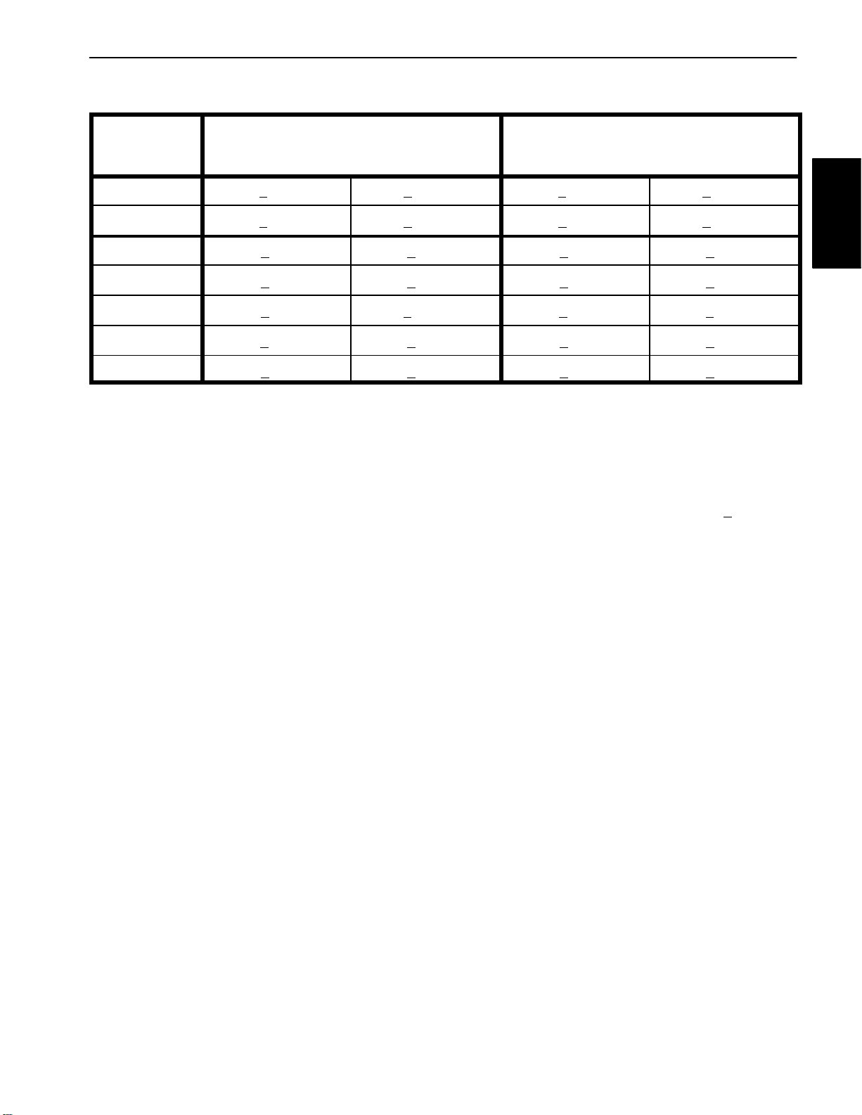
Standard Torque for Dry, Zinc Plated, and Steel Fasteners (Metric Fasteners)
Thread Size
Regular Height Nuts
Regular Height Nuts
Class 8.8 Bolts, Screws, and Studs with
(Class 8 or Stronger Nuts)
M5 X 0.8 57 + 5 in−lb 640 + 60 N−cm 78 + 7 in−lb 885 + 80 N−cm
M6 X 1.0 96 + 9 in−lb 1018 + 100 N−cm 133 + 13 in−lb 1500 + 150 N−cm
M8 X 1.25 19 + 2 ft−lb 26 + 3 N−m 27 + 2 ft−lb 36 + 3 N−m
M10 X 1.5 38 + 4 ft−lb 52 + 5 N−m 53 + 5 ft−lb 72 + 7 N−m
M12 X 1.75 66 + 7 ft−lb 90 + 10 N−m 92 + 9 ft−lb 125 + 12 N−m
M16 X 2.0 166 + 15 ft−lb 225 + 20 N−m 229 + 22 ft−lb 310 + 30 N−m
M20 X 2.5 325 + 33 ft−lb 440 + 45 N−m 450 + 37 ft−lb 610 + 50 N−m
Note: Reduce torque values listed in the table above
by 25% for lubricated fasteners. Lubricated fasteners
are defined as threads coated with a lubricant such as
oil, graphite, or thread sealant such as Loctite.
Note: Torque values may have to be reduced when
installing fasteners into threaded aluminum or brass.
The specific torque value should be determined based
on the fastener size, the aluminum or base material
strength, length of thread engagement, etc.
Note: The nominal torque values listed above are
based on 75% of the minimum proof load specified in
SAE J1199. The tolerance is approximately +
nominal torque value.
Class 10.9 Bolts, Screws, and Studs with
(Class 10 or Stronger Nuts)
10% of the
Product Records
and Maintenance
Groundsmaster 4000−D Page 2 − 5 Product Records and Maintenance
Page 16
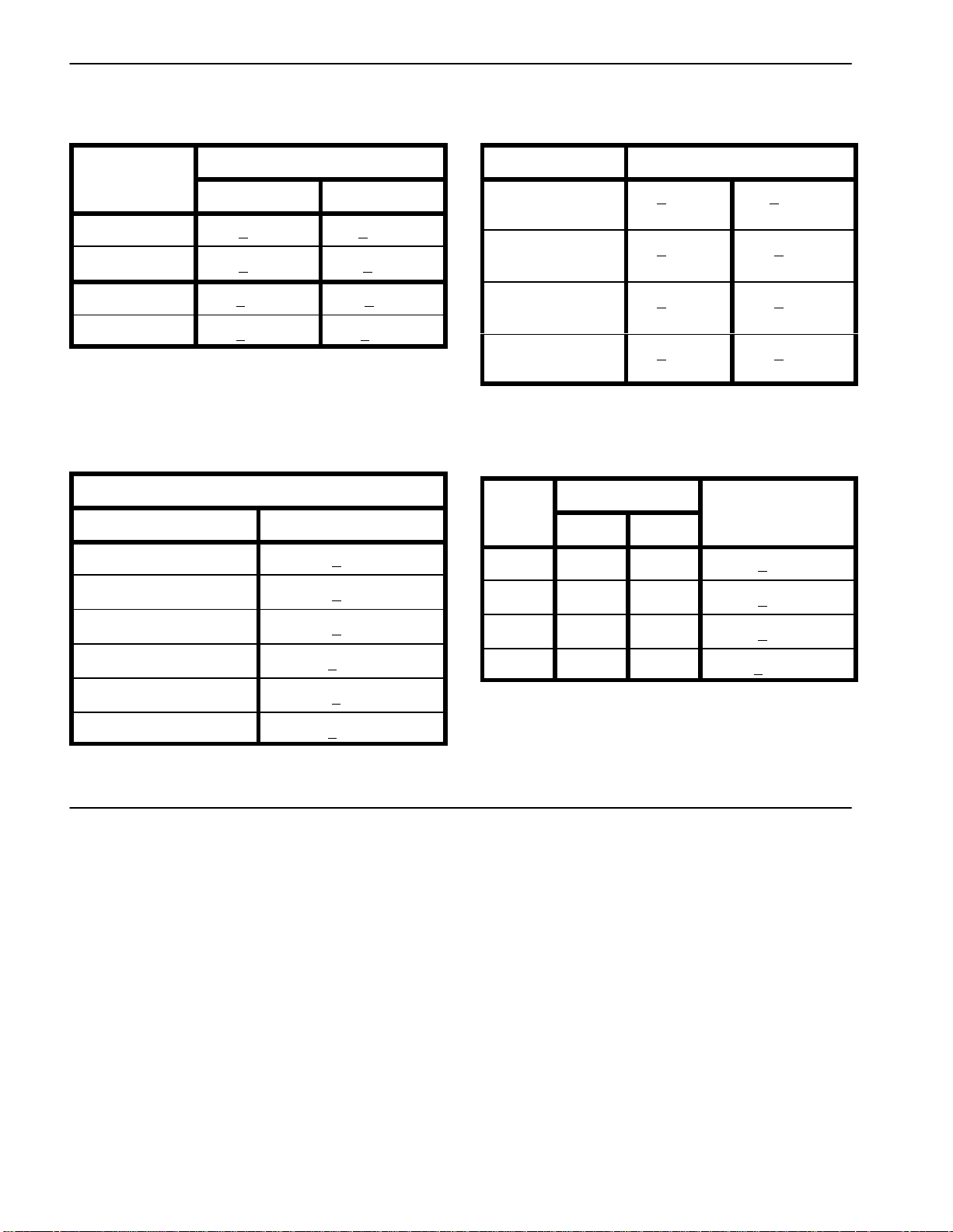
Other Torque Specifications
Thread Size
Size
Baseline Torque*
SAE Grade 8 Steel Set Screws
Recommended Torque
Square Head Hex Socket
1/4 − 20 UNC 140 + 20 in−lb 73 + 12 in−lb
5/16 − 18 UNC 215 + 35 in−lb 145 + 20 in−lb
3/8 − 16 UNC 35 + 10 ft−lb 18 + 3 ft−lb
1/2 − 13 UNC 75 + 15 ft−lb 50 + 10 ft−lb
Thread Cutting Screws
(Zinc Plated Steel)
Type 1, Type 23, or Type F
Thread Size Baseline Torque*
No. 6 − 32 UNC 20 + 5 in−lb
Wheel Bolts and Lug Nuts
Thread Size
7/16 − 20 UNF
Grade 5
1/2 − 20 UNF
Grade 5
M12 X 1.25
Class 8.8
M12 X 1.5
Class 8.8
** For steel wheels and non−lubricated fasteners.
Thread Cutting Screws
(Zinc Plated Steel)
Thread
No. 6 18 20 20 + 5 in−lb
Threads per Inch
Type A Type B
Recommended Torque**
65 + 10 ft−lb 88 + 14 N−m
80 + 10 ft−lb 108 + 14 N−m
80 + 10 ft−lb 108 + 14 N−m
80 + 10 ft−lb 108 + 14 N−m
No. 8 − 32 UNC 30 + 5 in−lb
No. 10 − 24 UNC 38 + 7 in−lb
1/4 − 20 UNC 85 + 15 in−lb
5/16 − 18 UNC 110 + 20 in−lb
3/8 − 16 UNC 200 + 100 in−lb
Conversion Factors
in−lb X 11.2985 = N−cm N−cm X 0.08851 = in−lb
ft−lb X 1.3558 = N−m N−m X 0.7376 = ft−lb
No. 8 15 18 30 + 5 in−lb
No. 10 12 16 38 + 7 in−lb
No. 12 11 14 85 + 15 in−lb
* Hole size, material strength, material thickness & finish
must be considered when determining specific torque
values. All torque values are based on non−lubricated
fasteners.
Groundsmaster 4000−DPage 2 − 6Product Records and Maintenance
Page 17

Table of Contents
GENERAL INFORMATION 2. . . . . . . . . . . . . . . . . . . . .
Stopping the Engine 2. . . . . . . . . . . . . . . . . . . . . . . . .
SPECIFICATIONS 3. . . . . . . . . . . . . . . . . . . . . . . . . . . .
ADJUSTMENTS 4. . . . . . . . . . . . . . . . . . . . . . . . . . . . . .
Run Solenoid 4. . . . . . . . . . . . . . . . . . . . . . . . . . . . . . .
SERVICE AND REPAIRS 6. . . . . . . . . . . . . . . . . . . . . .
Air Filter System 6. . . . . . . . . . . . . . . . . . . . . . . . . . . .
Exhaust System 8. . . . . . . . . . . . . . . . . . . . . . . . . . . .
Fuel System 10. . . . . . . . . . . . . . . . . . . . . . . . . . . . . . .
Check Fuel Lines and Connections 11. . . . . . . . . .
Drain and Clean Fuel Tank 11. . . . . . . . . . . . . . . . . .
Fuel Tank Removal 11. . . . . . . . . . . . . . . . . . . . . . . .
Fuel Tank Installation 11. . . . . . . . . . . . . . . . . . . . . . .
Chapter 3
Kubota Diesel Engine
Radiator 12. . . . . . . . . . . . . . . . . . . . . . . . . . . . . . . . . .
Engine 14. . . . . . . . . . . . . . . . . . . . . . . . . . . . . . . . . . . .
Engine Removal 15. . . . . . . . . . . . . . . . . . . . . . . . . .
Coupling Disassembly 17. . . . . . . . . . . . . . . . . . . . .
Coupling Assembly 17. . . . . . . . . . . . . . . . . . . . . . .
Engine Installation 17. . . . . . . . . . . . . . . . . . . . . . . .
KUBOTA WORKSHOP MANUAL, DIESEL ENGINE,
V2003−T SERIES
Kubota
Diesel Engine
Groundsmaster 4000−D Page 3 − 1 Kubota Diesel Engine (Rev. B)
Page 18

General Information
This Chapter gives information about specifications and
repair of the diesel engine used in the Groundsmaster
4000−D.
General maintenance procedures are described in your
Operator’s Manual. Information on engine troubleshooting, testing, disassembly and reassembly is identified in
the Kubota Workshop Manual, Diesel Engine, V2003−T
that is included at the end of this section.
Most repairs and adjustments require tools which are
commonly available in many service shops. Special
Stopping the Engine
IMPORTANT: Before stopping the engine after
mowing or full load operation, cool the turbo-charger by allowing the engine to idle at low speed for 5
minutes. Failure to do so may lead to turbo-charger
trouble.
tools are described in the Kubota Workshop Manual,
Diesel Engine, V2003−T. The use of some specialized
test equipment is explained. However, the cost of the
test equipment and the specialized nature of some repairs may dictate that the work be done at an engine repair facility.
Service and repair parts for Kubota engines are supplied through your Authorized Toro Distributor. If no
parts list is available, be prepared to provide your distributor with the Toro model and serial number.
Groundsmaster 4000−DPage 3 − 2Kubota Diesel Engine (Rev. B)
Page 19

Specifications
Item Description
Make / Designation Kubota, 4−Cycle, 4 Cylinder,
Water Cooled, Turbocharged, Diesel Engine
Horse Power 58 HP (43.3 kW) @ 2600 RPM
Bore mm (in.) 83.0 (3.27)
Stroke mm (in.) 92.4 (3.64)
Total Displacement cc (cu. in.) 1999 (122.12)
Firing Order 1−3−4−2
Combustion Chamber Spherical Type
Fuel No. 2 Diesel Fuel (ASTM D975)
Fuel Capacity liters (U.S. gallons) 72 (19.0)
Fuel Injection Pump Bosch Type Mini Pump (PFR)
Governor Centrifugal Mechanical
Low Idle (no load) 1450 + 50 RPM
High Idle (no load) 2730 + 30 RPM
Kubota
Diesel Engine
Direction of Rotation Counterclockwise (Viewed from Flywheel)
Compression Ratio 22.0:1
Injection Nozzle Bosch Throttle Type
Engine Oil SAE 10W30 or 10W40 Detergent (API CD, or higher)
Oil Pump Trochoid Type
Crankcase Oil Capacity liters (U.S. quarts) 7.6 (8.0) with Filter
Starter 12 VDC, 1.4 kW
Alternator/Regulator 12 VDC, 40 AMP
Coolant Capacity liters (U.S. quarts) 10.4 (11) with 0.9 (1.0) Reservoir
Engine Dry Weight kilograms (U.S. pounds) 184 (406)
Groundsmaster 4000−D Page 3 − 3 Kubota Diesel Engine (Rev. B)
Page 20
Adjustments
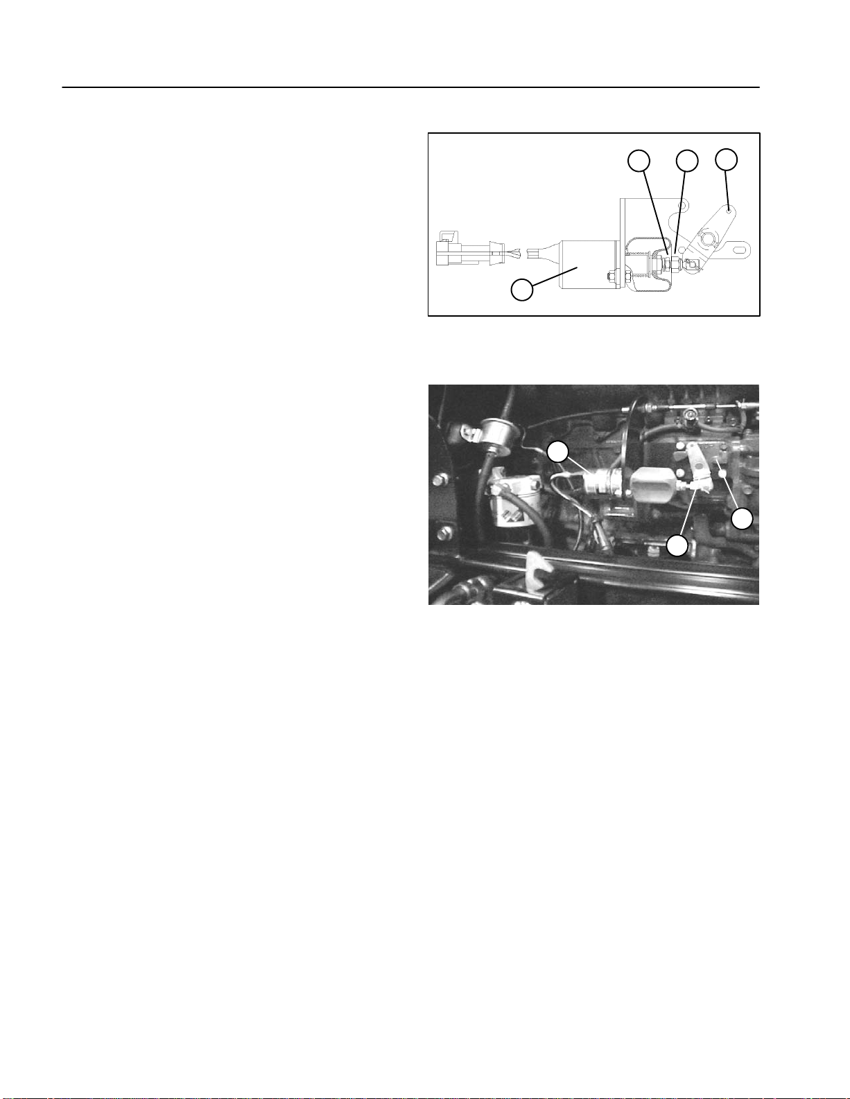
Run Solenoid
1. When ignition switch is in the RUN position, the run
solenoid should energize and position the fuel stop lever
to within 1/16” (1.6 mm) of stop on the injection pump.
2. If adjustment is needed, loosen lock nut and rotate
the threaded end of the swivel until the lever is properly
positioned.
3. Tighten lock nut. Recheck adjustment.
1
1. Run solenoid
2. Solenoid lever (run)
Figure 1
1
4
3. Swivel
4. Lock nut
2
3
1. Run solenoid
2. Solenoid lever (off)
3
2
Figure 2
3. Injection pump stop
Groundsmaster 4000−DPage 3 − 4Kubota Diesel Engine (Rev. B)
Page 21

This page is intentionally blank.
Kubota
Diesel Engine
Groundsmaster 4000−D Page 3 − 5 Kubota Diesel Engine (Rev. B)
Page 22
Service and Repairs
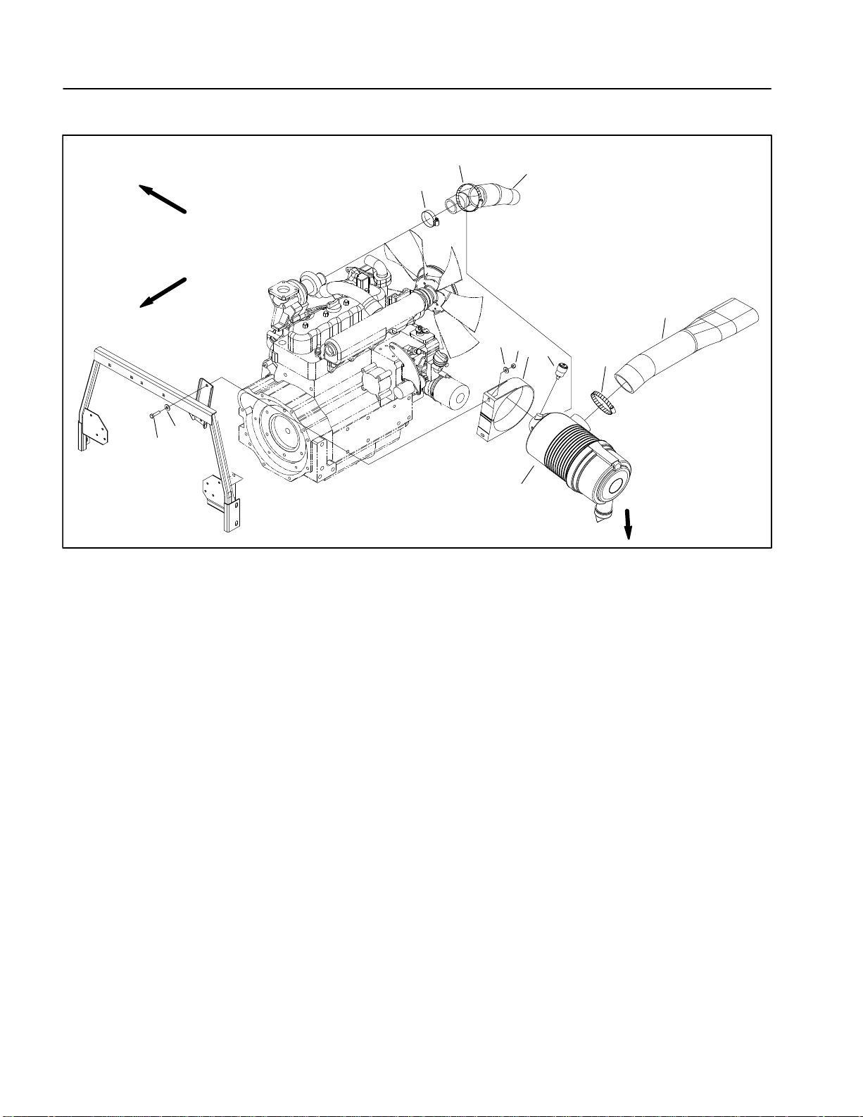
Air Filter System
RIGHT
FRONT
11
10
1. Air cleaner hose
2. Hose clamp
3. Air cleaner assembly
4. Indicator
Figure 3
5. Air cleaner strap
6. Lock nut
7. Hose clamp
8. Air cleaner hose
9
7
11
8
1
6
5
4
3
2
EVACUATOR
DIRECTION
9. Hose clamp
10. Cap screw
11. Flat washer
Groundsmaster 4000−DPage 3 − 6Kubota Diesel Engine (Rev. B)
Page 23
Removal
1. Remove air cleaner components as needed using
Figure 3 as a guide.
Installation
4
1
IMPORTANT: Any leaks in the air filter system will
cause serious engine damage. Make sure daily that
all air cleaner components are in good condition
and are properly secured during reassembly.
1. Reassemble air cleaner system using Figure 3 as a
guide.
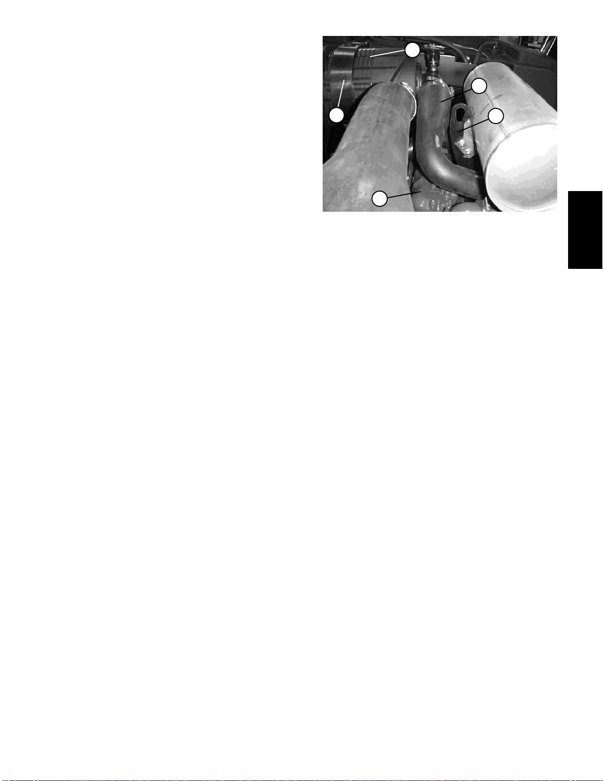
2. When installing air cleaner hose (8) between air
cleaner and turbo−charger (Fig. 4):
A. Make sure that hose does not contact engine
valve cover . To modify clearance, move and/or rotate
air cleaner body in air cleaner strap. Verify that tabs
in strap mesh fully with slots in air cleaner body.
B. Position hose to allow maximum clearance between air cleaner hose and muffler bracket.
3
2
1. Air cleaner hose
2. Engine valve cover
3. Air cleaner strap
Figure 4
4. Air cleaner body
5. Muffler bracket
5
Kubota
Diesel Engine
Groundsmaster 4000−D Page 3 − 7 Kubota Diesel Engine (Rev. B)
Page 24
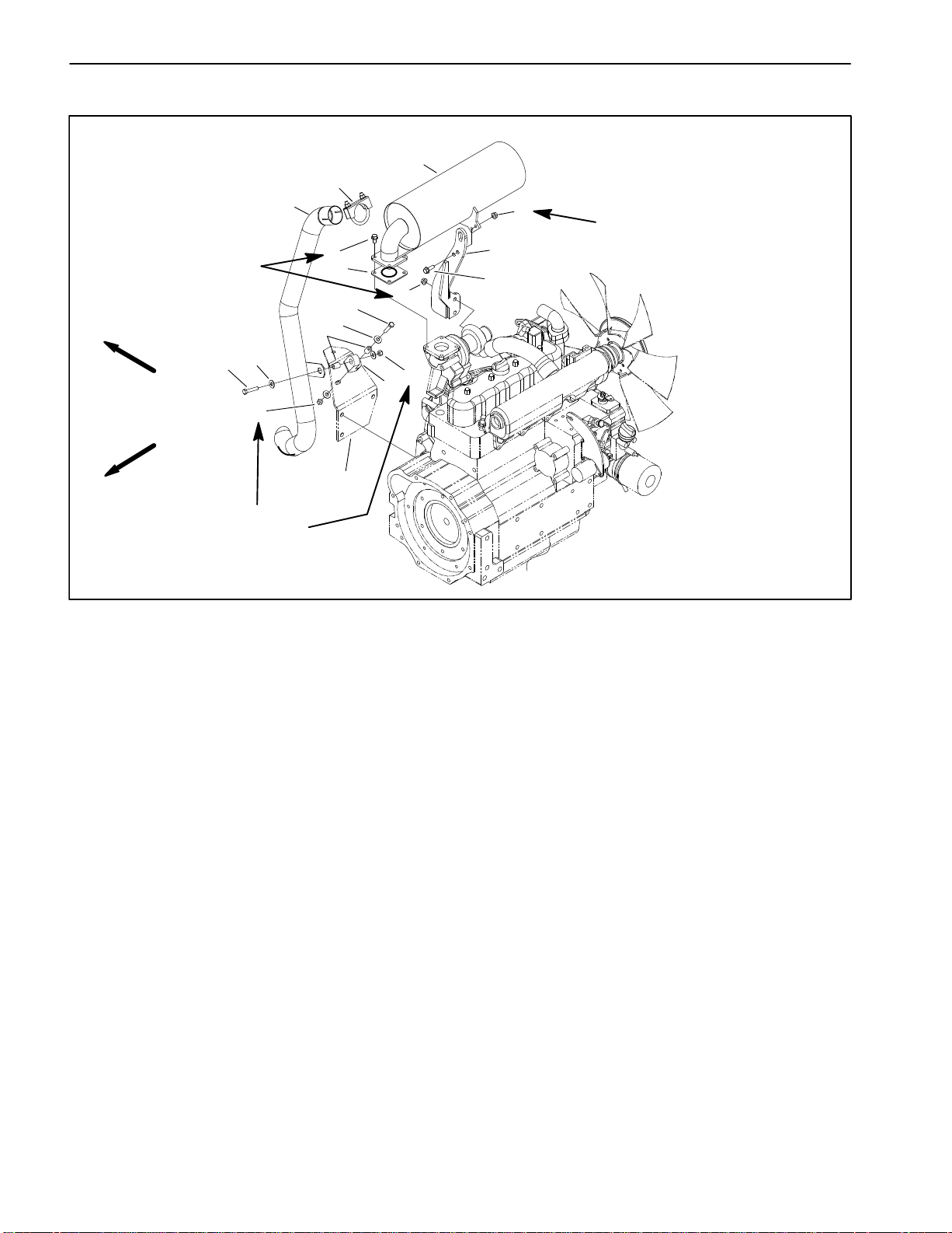
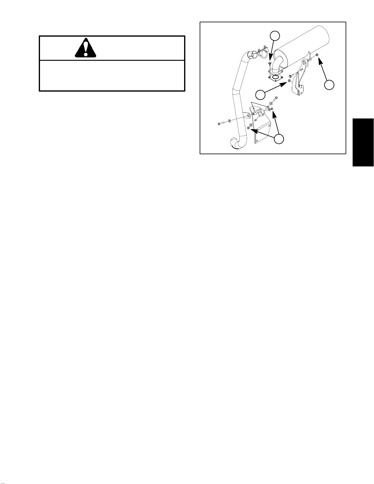
Exhaust System
16 to 22 ft−lb
(21 to 29 N−m)
RIGHT
FRONT
3
8
7
6
16 to 22 ft−lb
(21 to 29 N−m)
1
14
11
4
2
16 to 22 ft−lb
(21 to 29 N−m)
5
12
11
7
8
9
6
10
13
1. Muffler
2. Muffler bracket
3. Exhaust pipe
4. Flange head screw
5. Exhaust gasket
6. Lock nut
Figure 5
7. Cap screw
8. Flat washer
9. Spacer
10. Rubber hanger
11. Flange nut
12. Flange head screw
13. Engine mount
14. Muffler clamp
Groundsmaster 4000−DPage 3 − 8Kubota Diesel Engine (Rev. B)
Page 25
Removal
CAUTION
The muffler and exhaust pipe may be hot. To
avoid possible burns, allow the engine and exhaust system to cool before working on the muffler.
1. Park machine on alevel surface, lower cutting units,
stop engine, engage parking brake, and remove key
from the ignition switch.
2. Remove muffler and/or muffler bracket from the engine as necessary using Figure 5 as a guide.
3
2
4
1
Installation
IMPORTANT: If exhaust studs were removed from
engine cylinder head, thoroughly clean threads in
head and apply Loctite #277 (or equivalent) to stud
threads before installing studs into head.
Note: Makesure muffler flange and exhaust manifold
sealing surfaces are free of debris or damage that may
prevent a tight seal.
1. Install new gasket if original gasket is damaged or
torn.
IMPORTANT: Failure to follow the suggested mufflerfastener sequence mayresultin premature muffler failure.
2. Install muffler and/or muffler bracket to the engine
usingFigure5 as a guide. Hand tighten andthentorque
thefollowingfastenersfrom 16to22ft--lb(21to 29N--m)
in the sequence listed (Fig. 6):
A. Locknuts used on rubber hanger cap screws.
B. Flange nuts that secure muffler to muffler brack-
et.
Figure 6
Kubota
Diesel Engine
C. Flange head screws that securemufflerflangeto
engine.
D. Flange nuts that secure muffler bracket to engine.
3. Tailpipeshouldhaveequalclearancebetweenframe
and engine after installation.
Groundsmaster 4000--D Page 3 -- 9 Kubota Diesel Engine (Rev. B)
Rev. F
Page 26
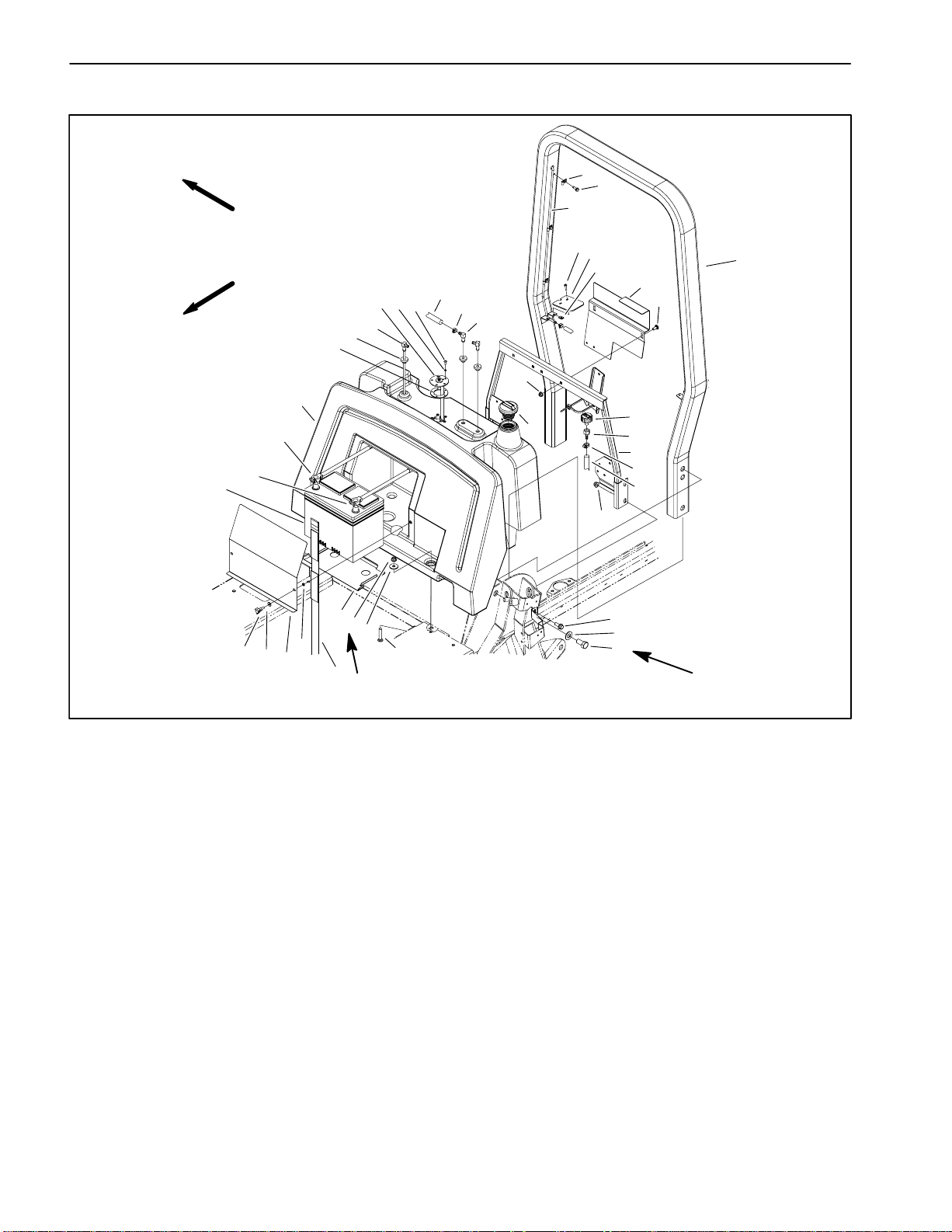
Fuel System
RIGHT
FRONT
14
20
21
38
39
37
36
24
25
26
27
28
29
30
35
34
2
22
31
41
23
33
1
3
32
4
5
40
6
7
1. Fuel tank
2. Fuel tank bracket
3. Air breather
4. Female hose barb
5. Tank support assembly
6. Fuel hose
7. Locking flange nut
8. Cap screw
9. Flat washer
10. Cap screw
11. Carriage screw
12. Washer
13. Battery strap
14. Battery
18
17
16
15
19
7
12
11
13
60 to 80 in−lb
(6.8 to 9 N−m)
15. Retaining ring
16. Battery cover
17. Flat washer
18. Knob
19. Battery plate
20. Negative cable
21. Positive cable
22. Carriage screw
23. Gasket
24. Bushing
25. Stand pipe
26. Fuel sender
27. Lock washer
28. Phillips head screw
8
9
10
135 to 165 ft−lb
(183 to 223 N−m)
Figure 7
29. Fuel hose
30. Hose clamp
31. Elbow fitting
32. Fuel cap
33. Locking flange nut
34. Speed nut
35. Tank cover
36. Phillips head screw
37. Vent tube
38. Insulated clip
39. Washer head screw
40. Hose clamp
41. ROPS assembly
Groundsmaster 4000−DPage 3 − 10Kubota Diesel Engine (Rev. B)
Page 27
Fuel Tank Installation
DANGER
Because diesel fuel is highly flammable, use caution when storing or handling it. Do not smoke
while filling the fuel tank. Do not fill fuel tank
while engine is running, hot, or when machine is
in an enclosed area. Always fill fuel tank outside
and wipe up any spilled diesel fuel before starting the engine. Store fuel in a clean, safety−approved container and keep cap in place. Use diesel fuel for the engine only; not for any other
purpose.
Check Fuel Lines and Connections
Check fuel lines and connections periodically as recommended in the O p erator’s Manual. Check lines for deterioration, damage, leaking, or loose connections.
Replace hoses, clamps, and connections as necessary.
Drain and Clean Fuel Tank
Drain and clean the fuel tank periodically as recommended in the Operator’s Manual. Also, drain and clean
the fuel tank if the fuel system becomes contaminated
or if the machine is to be stored for an extended period.
1. Install fuel tank using Figure 7 as a guide.
A. Torque two locking flange nuts that secure the
fuel tank to the frame from 60 to 80 in−lb (7 to 9 N−m).
2. Install two (2) tank covers to ROPS assembly.
3. Connect fuel hose to the standpipe and venting
hoses to the elbow fittings.
4. Connect electrical wiring to the sending unit.
A. Connect white wire to the center terminal and
black wire to any of the screws that secure the fuel
sender to the fuel tank.
B. Apply skin−over grease to the wire terminal connections.
CAUTION
Connecting battery cables to the wrong battery
post could result in personal injury and/or damage to the electrical system.
Kubota
Diesel Engine
To clean fuel tank, flush tank out with clean diesel fuel.
Make sure tank is free of contaminates and debris.
Fuel Tank Removal (Fig. 7)
1. Park machine on a level surface, lower cutting units,
stop engine, engage parking brake, and remove key
from the ignition switch.
2. Raise seat and hood.
3. Remove battery cover and strap. Disconnect negative battery cable first and then positive battery cable.
Remove battery from machine.
4. Use a fuel transfer pump to remove fuel from the fuel
tank and into a suitable container.
5. Disconnect electrical wiring from the sending unit.
6. Disconnect fuel hose from the standpipe and venting
hoses from elbow fittings in top of tank.
7. Remove phillips head screws that secure two (2)
tank covers to ROPS assembly. Remove tank covers.
5. Position battery in machine. Connect positive battery
cable first and then negative battery cable. Install battery strap and cover.
6. Lower seat and hood.
7. Fill fuel tank (see Operator’s Manual).
8. Remove fuel tank using Figure 7 as a guide.
Groundsmaster 4000−D Page 3 − 11 Kubota Diesel Engine (Rev. B)
Rev. E
Page 28
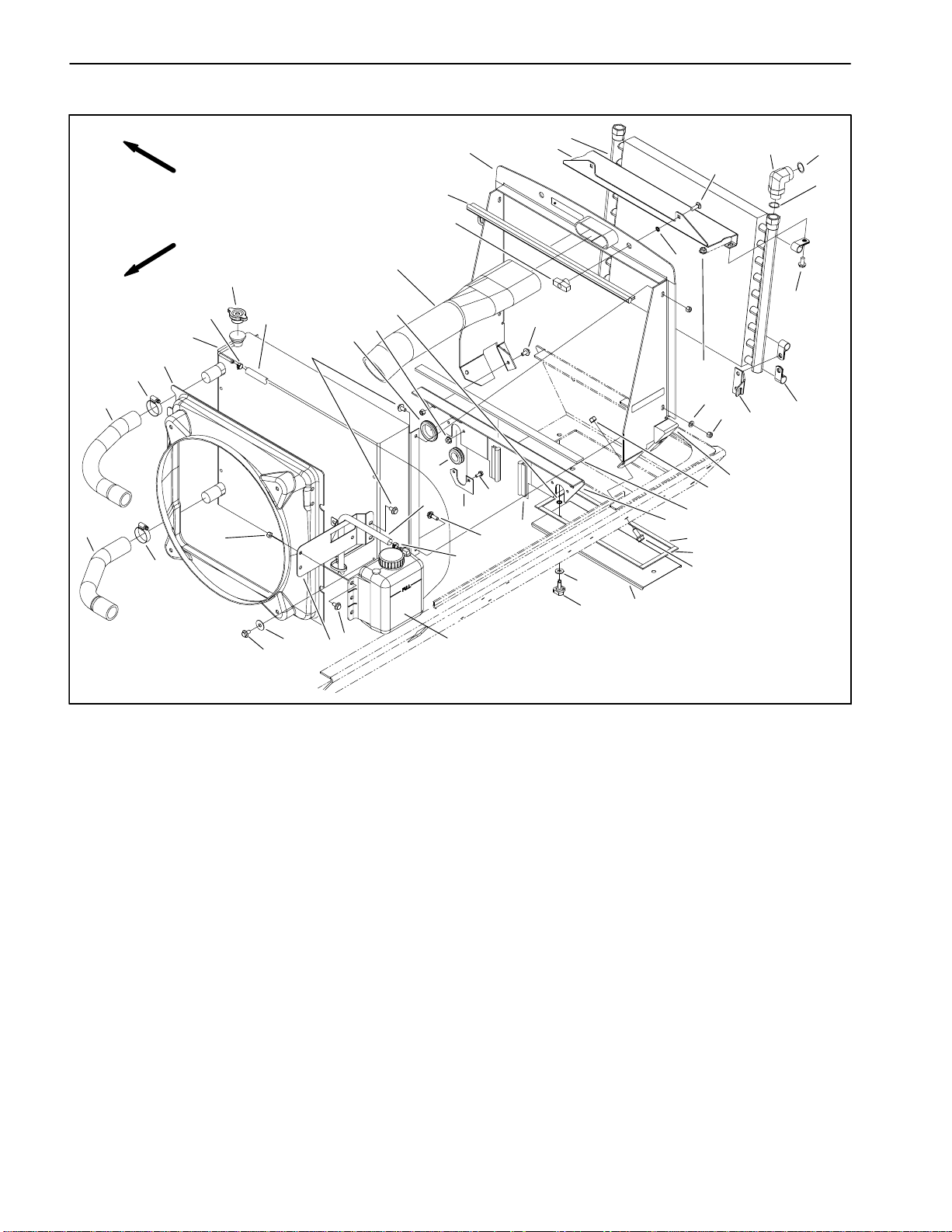
Radiator
18
20
21
23
46
22
RIGHT
FRONT
47
17
16
19
45
1
27
24
25
13
14
15
35
11
38
10
37
41
34
12
32
31
2
26
3
33
28
30
8
29
10
11
9
7
6
12
5
4
8
6
39
40
36
1. Radiator cap
2. Foam strip
3. Foam strip
4. Lower radiator hose
5. Upper radiator hose
6. Hose clamp
7. Radiator shroud
8. Lock nut
9. Radiator
10. Hose clamp
11. Reservoir hose
12. Flange head screw
13. Grommet
14. Flange nut
15. Retaining ring
16. Knob
12
42
12
44
17. Bulb seal
18. Radiator support assembly
19. Retaining ring
20. Oil cooler bracket
21. Oil cooler
22. Carriage screw
23. Hydraulic fitting
24. Flange head screw
25. Clamp
26. Flange nut
27. Oil cooler bracket (RH shown)
28. Flat washer
29. Foam plug
30. Lock nut
31. Foam strip
32. Lower radiator support
43
Figure 8
33. Flange head screw
34. Bulb seal
35. Grommet
36. Frame cover
37. Flange head screw
38. Plate
39. Flat washer
40. Knob
41. Shoulder bolt
42. Flat washer
43. Coolant reservoir
44. Coolant reservoir bracket
45. O−ring
46. O−ring
47. Air cleaner hose
Groundsmaster 4000−DPage 3 − 12Kubota Diesel Engine (Rev. B)
Page 29
Removal
Installation
1. Park machine on a level surface, lower cutting units,
stop engine, engage parking brake, and remove key
from the ignition switch.
2. Open engine hood on the machine.
CAUTION
Do not open radiator cap or drain coolant if the
radiator or engine is hot. Pressurized, hot coolant can escape and cause burns.
Ethylene−glycol antifreeze is poisonous. Dispose of coolant properly , or store it in a properly
labeled container away from children and pets.
3. Drain radiator into a suitable container using the radiator drain. The radiator drain hose is located near the
engine oil filter.
4. Disconnect hoses (upper and lower) from the radiator.
5. Remove air cleaner hose.
1. Remove any plugs used during the removal proce-
dure.
2. Position radiator to the support frame. Secure radia-
tor to the support frame with lock nuts, flat washers, and
screws.
3. Attach radiator shroud to the radiator with flange
screws and flat washers. Make sure that clearance between shroud and fan is at least .180” (4.6 mm) at all
points.
4. Connect reservoir hose to the vent tube.
5. Connect hoses (upper and lower) to the radiator.
6. Reinstall air cleaner hose.
7. Make sure radiator drain is closed. Fill radiator with
coolant (see Operator’s Manual).
8. Close and secure engine hood on the machine.
Kubota
Diesel Engine
6. Disconnect reservoir hose from the vent tube.
7. Detach radiator shroud from the radiator by removing four flange head screws and flat washers. Position
shroud away from radiator.
8. Remove screws, flat washers and lock nuts securing
the radiator to the support frame. Pull radiator from the
machine.
9. Plug any radiator or hose openings to prevent contamination.
Groundsmaster 4000−D Page 3 − 13 Kubota Diesel Engine (Rev. B)
Page 30

Engine
12
10
5
17 to 21 ft−lb
(23 to 28.5 N−m)
47
45
46
42
40
43
44
RIGHT
FRONT
49
40
41
39
42
31
38
48
37
(47.5 to 58.3 N−m)
6
29
35
36
35 to 43 ft−lb
26
10
30
32
33
34
10 to 12 ft−lb
(13.6 to 16.3 N−m)
29
27
28
6
7
8
9
10
13
11
25
16
14
17
18
12
10
15
19
20
21
22
3
2
4
1
23
24
23
1. Engine
2. Engine mount bracket (RH shown)
3. Lock washer
4. Cap screw
5. Barb fitting
6. Hose clamp
7. Hose
8. Fuel line
9. Fuel filter
10. Fuel line
11. Coolant drain hose
12. Hose clamp
13. Cap screw
14. Barb fitting (female)
15. Coolant drain cock fitting
16. Engine mount bracket (RH shown)
17. Lock washer
18. Cap screw
Figure 9
19. Lock washer
20. Cap screw
21. Cap screw
22. Rubber engine mount
23. Flange head locking nut
24. Rebound washer
25. Hose clamp
26. Fuel line
27. Coupler spacer
28. Dowel
29. Lock washer
30. Shoulder bolt
31. Cap screw
32. Spring center coupling
33. Plate pin
34. Cap screw
35. Pump adapter plate
36. Lock washer
37. Cap screw
38. Traction cylinder assembly
39. Cap screw
40. O−ring
41. Cylinder piston
42. Back−up ring
43. Retaining ring
44. Seal
45. Hydraulic fitting
46. O−ring
47. O−ring
48. Shim plate
49. Hydraulic hose
Groundsmaster 4000−DPage 3 − 14Kubota Diesel Engine (Rev. B)
Page 31

Engine Removal
1. Park machine on a level surface, lower cutting units,
stop engine, engage parking brake, and remove key
from the ignition switch.
2. Remove battery cover and strap. Disconnect negative battery cable first and then positive battery cable.
Remove battery from machine.
1
3
3. Open engine hood.
CAUTION
Do not open radiator cap or drain coolant if the
radiator or engine is hot. Pressurized, hot coolant can escape and cause burns.
Ethylene−glycol antifreeze is poisonous. Dispose of coolant properly , or store it in a properly
labeled container away from children and pets.
4. Drain coolant from the radiator into a suitable container (see Radiator Removal). Disconnect coolant
hoses from the radiator.
CAUTION
The muffler and exhaust pipe may be hot. To
avoid possible burns, allow the exhaust system
to cool before working on or near the muffler.
3
1. Temperature sender
2. Alternator
3
2
1
1. Run solenoid
2. Fuel line
3. Throttle cable
2
Figure 10
3. Coolant hose
Kubota
Diesel Engine
4
5
Figure 11
4. Cable jam nut
5. Cable washer/lock nut
5. Remove exhaust system from engine (see Muffler
Removal).
6. Remove air cleaner system from engine (see Air
Cleaner Removal).
7. Note location of cable ties used to secure wires. Disconnect wires and/or electrical connections from the following electrical components:
A. The temperature sender and alternator (Fig 10).
Note: red wire attached to alternator with washer,
nut, and boot does not have to be removed.
B. The engine run solenoid and fuel pump (Fig. 12).
C. The high temperature shutdown switch and glow
plug (Fig. 13).
D. Battery, frame, and wire harness ground at the
engine block (Fig. 14).
E. The electric starter (Fig. 14) and low oil pressure
switch (near electric starter).
3
2
1. Run solenoid
2. Fuel pump
1
Figure 12
3. Fuel filter
Groundsmaster 4000−D Page 3 − 15 Kubota Diesel Engine (Rev. B)
Page 32

8. Disconnect fuel line from injection pump (Fig. 11).
9. Disconnect throttle cable from the speed control lever by removing the washer and lock nut. Loosen jam
nut and take cable from mounting bracket (Fig. 11).
10.Remove coolant reservoir and bracket from fan
shroud.
11.Remove four flange head screws and flat washers
securing the fan shroud to the radiator.
12.Remove traction cylinder assembly from engine
adapter plate. It is not necessary to remove the hydraulic hose from the cylinder. Locate and remove shim plate
from between traction cylinder and adapter plate.
13.Disconnect two wires from neutral switch on hydraulic traction pump.
IMPORTANT: Support hydraulic pump assembly to
prevent it from falling and being damaged.
14.Remove hydraulic pump assembly from engine (see
Pump Assembly in Chapter 4 − Hydraulic Systems).
15.Make sure all cable ties securing the wiring harness,
fuel lines, or hydraulic hoses to the engine are removed.
16.Connect hoist or lift to the front and rear lift tabs on
engine.
3
1. Glow plug wire
2. High temp shutdown
1
2
Figure 13
3. Engine lift tab
7
4
5
6
7
1
2
17.Remove flange head locking nuts, rebound washers,
and cap screws securing the engine brackets to the engine mounts.
CAUTION
One person should operate lift or hoist while the
other person guides the engine out of the machine.
IMPORTANT: Make sure not to damage the engine,
fuel and hydraulic lines, electrical harness, or other
parts while removing the engine.
18.Slowly remove engine from the machine.
19.If necessary, remove engine mount brackets from
the engine using Figure 9 as a guide.
Figure 14
1. Battery cable (+)
2. Battery cable (−)
3. Engine to frame ground
4. Engine wire harness
3
5. Alternator wire
6. Fusible link harness
7. Cable tie
Groundsmaster 4000−DPage 3 − 16Kubota Diesel Engine (Rev. B)
Page 33

Coupling Disassembly
.
1. Remove adapter plate, spring coupling, and coupling spacer from engine using Figure 9 as a guide.
Coupling Assembly
1. Position coupling spacer to engine and align mounting holes. Use two shoulder bolts and lockwashers in the
positions shown in Figure 15 to secure the spacer to the
half threaded holes in engine flywheel. Torque shoulder
bolts from 10 to 12 ft−lb (13.6 to 16.3 N−m).
2. Install four cap screws and lockwashers to coupling
spacer and flywheel. Torque cap screws from 17 to 21
ft−lb (23 to 28.5 N−m).
3. Place dowels in locating holes of coupling spacer
(Fig. 15).
4. Position spring center coupling (coil springs toward
engine (Fig. 16)) over dowels. Secure coupling to coupling spacer with cap screws and lockwashers. Torque
cap screws from 35 to 43 ft−lb (47.5 to 58.3 N−m).
4
2
1
1. Coupling spacer
2. Shoulder bolt position
3
3
Figure 15
3. Cap screw position
4. Dowel position
2
4
Kubota
Diesel Engine
5. Install plate pins into engine casting. Position pump
adaptor plate to engine using plate pins as alignment
points. Secure adaptor plate with cap screws and lock
washers using a star pattern tightening procedure.
Engine Installation
1. If removed, install engine mount brackets to the engine using Figure 9 as a guide.
2. Connect hoist or lift to the front and rear lift tabs on
engine.
3. Position fan shroud around the engine fan.
CAUTION
One person should operate lift or hoist while the
other person guides the engine into the machine
IMPORTANT: Make sure not to damage the engine,
fuel and hydraulic lines, electrical harness, or other
parts while installing the engine.
Hydraulic
Pump Side
Spring Center
Coupling
Engine Side
Figure 16
7. Install coolant reservoir bracket and reservoir to fan
shroud.
8. Connect throttle cable to the speed control lever with
washer and lock nut. Install cable to mounting bracket
(Fig. 11). Adjust throttle cable (see Operator’s Manual).
9. Connect fuel line to the injection pump (Fig. 11).
10.Install traction cylinder assembly to engine adapter
plate.
4. Slowly lower engine into the machine.
5. Align engine to the rubber engine mounts and secure
with cap screws, rebound washers, and flange head
locking nuts.
6. Secure fan shroud to the radiator with four cap
screws, flat washers, and locknuts. Make sure that
IMPORTANT: Support hydraulic pump assembly to
prevent it from falling and being damaged.
11.Install hydraulic pump assembly to engine (see
Pump Assembly in Chapter 4 − Hydraulic Systems).
12.Connect two wires to neutral switch on traction
pump.
clearance between shroud and fan is at least .180” (4.6
mm) at all points.
13.Connect wires and/or electrical connections to the
Groundsmaster 4000−D Page 3 − 17 Kubota Diesel Engine (Rev. B)
Page 34

following electrical components:
A. The temperature sender and alternator (Fig 10).
17.Check position of wires, fuel lines, hydraulic hoses,
and cables for proper clearance with rotating, high temperature, and moving components.
B. The engine run solenoid and fuel pump (Fig. 12).
C. The high temperature shutdown switch and glow
plug (Fig. 13).
D. Battery, frame, and wire harness ground to the
engine block (Fig. 14).
E. The starter (Fig. 14) and low oil pressure switch
(near starter).
14.Install air cleaner assembly to the engine (see Air
Cleaner Installation).
15.Install exhaust system to machine (see Muffler
Installation).
16.Connect coolant hoses to the radiator. Make sure radiator drain is shut. Fill radiator and reservoir with coolant (see Operator’s Manual).
18.Position battery to machine. Connect positive battery cable first and then negative battery cable. Secure
battery to machine with strap and cover.
19.Check and adjust engine oil as needed (see Operator’s Manual).
20.Check and adjust hydraulic oil as needed (see Operator’s Manual).
21.Bleed fuel system (see Operator’s Manual).
22.Operate hydraulic controls to properly fill hydraulic
system (see Charge Hydraulic System in Chapter 4 −
Hydraulic Systems).
Groundsmaster 4000−DPage 3 − 18Kubota Diesel Engine (Rev. B)
Page 35

Table of Contents
Chapter 4
Hydraulic System
SPECIFICATIONS 2.............................
GENERAL INFORMATION 3.....................
Hydraulic Hoses 3............................
Hydraulic Fitting Installation 3...................
Towing Traction Unit 5.........................
Check Hydraulic Fluid 5.......................
HYDRAULIC SCHEMATICS 6....................
Hydraulic Schematic (S/N below 220999999) 6...
Hydraulic Schematic (S/N above 230000000) 7...
HYDRAULIC FLOW DIAGRAMS 8................
Traction Circuit 8..............................
Lower Cutting Unit 10..........................
Raise Cutting Unit 12..........................
Mow 14......................................
Steering Circuit 16............................
SPECIAL TOOLS 18............................
Hydraulic Pressure Test Kit 18..................
Hydraulic Tester (Pressure and Flow) 18.........
Hydraulic Test Fitting Kit 19.....................
Measuring Container 19.......................
TROUBLESHOOTING 20........................
TESTING 23...................................
Test No. 1: Traction Circuit Charge Pressure 24...
Test No. 2: Traction Circuit Relief Pressure 26....
Test No. 3: Cutting Deck Circuit Pressure 28......
Test No. 4: Cutting Deck Gear Pump Flow 30.....
Test No. 5: Cutting Deck Manifold
Relief Pressure 32...........................
Test No. 6: Cutting Deck Motor Case
Drain Leakage 34...........................
Test No. 7: Steering Circuit Relief Pressure 36....
Test No. 8: Lift/Lower Circuit Relief Pressure 38...
Test No. 9: Steering and Lift/Lower
Gear Pump Flow 40.........................
Test No. 10: Counterbalance Pressure 42........
Test No. 11: Rear Traction Circuit (RV5)
Relief Pressure 44...........................
Test No. 12: Traction Circuit Reducing
Valve (PR) Pressure 46......................
ADJUSTMENTS 48.............................
Adjust Front Cutting Unit Lift Flow Control 48.....
SERVICE AND REPAIRS 49.....................
General Precautions for Removing and
Installing Hydraulic System Components 49....
Check Hydraulic Lines and Hoses 49............
Flush Hydraulic System 50.....................
Charge Hydraulic System 51...................
Gear Pump 52................................
Gear Pump Service 54.........................
Piston (Traction) Pump 58......................
Piston (Traction) Pump Service 60..............
Piston Pump Control Assembly 64..............
Hydraulic Control Manifold: 4 Wheel Drive 66.....
Hydraulic Control Manifold Service:
4 Wheel Drive 68............................
Hydraulic
Hydraulic Control Manifold Service: Deck Drive 71
Hydraulic Control Manifold: Cutting Deck
Lift/Lower 72................................
Hydraulic Control Manifold Service: Cutting
Deck Lift/Lower 73..........................
Hydraulic Control Manifold: Filter Manifold 74.....
Hydraulic Control Manifold Service:
Filter Manifold 75............................
Hydraulic Control Manifold: Flow Divider 76......
Hydraulic Control Manifold Service:
Flow Divider 77.............................
Rear Axle Motor 78...........................
Front Wheel Motors 80........................
Rear Axle/Front Wheel Motor Service 82.........
Cutting Deck Motor 85.........................
Cutting Deck Motor Service 86..................
Lift/Lower Control Valve 90.....................
Lift/Lower Control Valve Service 92..............
Steering Valve 94.............................
Steering Valve Service 96......................
Side Deck Lift Cylinder 98......................
Front Deck Lift Cylinder 100....................
Lift Cylinder Service 102.......................
Steering Cylinder 104..........................
Steering Cylinder Service 106..................
Hydraulic Reservoir 108.......................
Hydraulic Oil Cooler 110.......................
Control Manifold: Deck Drive 70........
System
Hydraulic
Groundsmaster 4000--D Hydraulic System (Rev. B)Page 4 -- 1
Page 36

Specifications
Item Description
Piston (Traction) Pump Variable displacement piston pump
System Relief Pressure: Forward 4000 PSI (274 bar)
System Relief Pressure: Reverse 5000 PSI (343 bar)
Charge Pressure 250 PSI (17 bar)
Gear Pump 3 section, positive displacement gear type pump
Steering Relief Pressure 1350 PSI (93 bar)
Lift/Lower Relief Pressure 1500 PSI (103 bar)
Front Wheel Motors Fixed displacement piston motors
Rear Axle Motor Fixed displacement piston motor
Cutting Deck Motors Gear motor
Relief Pressure (front and left side) 3000 PSI (207 bar)
Relief Pressure (right side) 2000 PSI (137 bar)
Hydraulic Filters 10 Micron spin--on cartridge type
In--line Suction Strainer 100 mesh (in reservoir)
Hydraulic Reservoir 8 gal. (30.3 l)
Hydraulic Oil See Operator’s Manual
Groundsmaster 4000--DHydraulic System (Rev. B) Page 4 -- 2
Page 37

General Information
Hydraulic Hoses
Hydraulic hoses are subject to extreme conditions such
as pressure differentials during operation and exposure
to weather, sun, chemicals, very warm storage conditions, or mishandling during operation or maintenance.
These conditions can cause damage or premature deterioration. Some hoses are more susceptible to these
conditions than others. Inspect the hoses frequently for
signs of deterioration or damage.
WARNING
Before disconnecting or performing any work
on hydraulic system, relieve all pressure in
system. Stop engine; lower or support box
and/or other attachment(s).
When replacing a hydraulic hose, be sure that the hose
is straight (not twisted) before tightening the fittings.
This can be done by observing the imprint on the hose.
Use two wrenches; hold the hose straight with one and
tighten the hose swivel nut onto the fitting with the other.
Hydraulic Fitting Installation
O--Ring Face Seal
1. Make sure both threads and sealing surfaces are
free of burrs, nicks, scratches, or any foreign material.
2. Make sure the O--ring is installed and properly
seated in the groove. It is recommended that the O--ring
be replaced any time the connection is opened.
3. Lubricate the O--ring with a light coating of oil.
4. Put the tube and nut squarely into position on the
face seal end of the fitting and tighten the nut until finger
tight.
Keep body and hands away from pin hole leaks
or nozzles that eject hydraulic fluid under high
pressure. Use paper or cardboard, not hands,
to search for leaks. Hydraulic fluid escaping
under pressure can have sufficient force to
penetrate the skin and cause serious injury. If
fluid is injected into the skin, it must be surgically removed within a few hours by a doctor
familiar with this type of injury. Gangrene may
result from such an injury.
Nut
Sleeve
Seal
Body
Figure 1
System
Hydraulic
5. Mark the nut and fitting body. Hold the body with a
wrench. Use another wrench to tighten the nut to the correct Flats From Finger Tight (F.F.F.T.). The markings on
the nut and fitting body will verify that the connection has
been tightened.
Siz e F.F.F. T.
4 (1/4 in. nominal hose or tubing) 0.75 +
6(3/8in.) 0.75+
8(1/2in.) 0.75+
10 (5/8 in.) 1.00 +
12 (3/4 in.) 0.75 +
16 (1 in.) 0.75 +
0.25
0.25
0.25
0.25
0.25
0.25
Groundsmaster 4000--D Hydraulic System (Rev. B)Page 4 -- 3
Final
Position
Mark Nut
and Body
Extend Line
Initial
Position
Finger Tight After Proper Tightening
Figure 2
Page 38

SAE Straight Thread O--Ring Port -- Non--adjustable
1. Make sure both threads and sealing surfaces are
free of burrs, nicks, scratches, or any foreign material.
2. Always replace the O--ring seal when this type of fitting shows signs of leakage.
3. Lubricate the O--ring with a light coating of oil.
O--Ring
4. Install the fitting into the port and tighten it down full
length until finger tight.
5. Tighten the fitting to the correct Flats From Finger
Tight (F.F.F.T.).
Siz e F.F.F. T.
4 (1/4 in. nominal hose or tubing) 1.00 +
6(3/8in.) 1.50+
8(1/2in.) 1.50+
10 (5/8 in.) 1.50 +
12 (3/4 in.) 1.50 +
16 (1 in.) 1.50 +
0.25
0.25
0.25
0.25
0.25
0.25
SAE Straight Thread O--Ring Port -- Adjustable
1. Make sure both threads and sealing surfaces are
free of burrs, nicks, scratches, or any foreign material.
2. Always replace the O--ring seal when this type of fitting shows signs of leakage.
3. Lubricate the O--ring with a light coating of oil.
4. Turn back the jam nut as far as possible. Make sure
the back up washer is not loose and is pushed up as far
as possible (Step 1).
Figure 3
Lock Nut
Back--up Washer
O--Ring
5. Install the fitting into the port and tighten finger tight
until the washer contacts the face of the port (Step 2).
6. To put the fitting in the desired position, unscrew it by
the required amount, but no more than one full turn
(Step 3).
7. Hold the fitting in the desired position with a wrench
and turn the jam nut with another wrench to the correct
Flats From Finger Tight (F.F.F.T.) (Step 4).
Siz e F.F.F. T.
4 (1/4 in. nominal hose or tubing) 1.00 +
6(3/8in.) 1.50+
8(1/2in.) 1.50+
10 (5/8 in.) 1.50 +
12 (3/4 in.) 1.50 +
16 (1 in.) 1.50 +
0.25
0.25
0.25
0.25
0.25
0.25
Figure 4
Step 3Step 1
Step 2 Step 4
Figure 5
Groundsmaster 4000--DHydraulic System (Rev. B) Page 4 -- 4
Page 39

Towing Traction Unit
IMPORTANT: If towing limits are exceeded, severe
damage to the piston pump may occur.
If it becomes necessary to tow (or push) the machine,
tow (or push) in a forward direction only and at a
speed below 3 mph. The piston (traction) pump is
equipped with a by--pass valve that needs to be turned
o
for towing. See Operator ’s Manual for Towing Pro-
90
cedures.
See Operator’s Manual for towing instructions in reverse.
Check Hydraulic Fluid
The Groundsmaster 4000--D hydraulic system is designed to operate on anti--wear hydraulic fluid. The reservoir holds about 8 gallons (30.3 liters) of hydraulic
fluid. Check level of hydraulic fluid daily. See Operator’s Manual for fluid level checking procedure and oil
recommendations.
1
Figure 6
1. By--pass valve location
1
System
Hydraulic
Figure 7
1. Hydraulic reservoir cap
Groundsmaster 4000--D Hydraulic System (Rev. B)Page 4 -- 5
Page 40

Hydraulic Schematics
470
PSI
A1
C1
G
CB
A2
1.50 BORE
4.00 STROKE
.750 ROD
2.50 BORE
6.50 STROKE
LIFT/LOWER
1.125 ROD
LH WING
CONTROL VALVE
DECK LIFT
CYL3
B
A
C
CYL1
DECK
FRONT
D
LIFT
C2
CYL2
REAR
50
PSI
CHG M1
CHG
E
CYL4
F
RH WING
DECK LIFT
FILTER
PD1
CYL
SV
2
CYLINDER
TRANSPORT
12.6:1
2.01
M1
5A
RV5
7
P1
CHG
G
FRONT
5.2:1
2.48
2.48
5.2:1
M2
GAGE
T
PD2
5B
PR
CV
3
8
P2
G
de--energized
All solenoids are shown as
Hydraulic Schematic
(Serial Numbers below 220999999)
Groundsmaster 4000--D
G
600
CD
RV
250 PSI
P2
BY1
PSI
FILTER
5 PSI
T
SV1
BR1
CD
P1
40
PSI
OIL
COOLER
P2
CD
OR1
.063
5000
PSI
PROPORTIONAL
FLOW DIVIDER
2.48
1.2
1.2
.58
G
PSI
VALV E
TOW
P1
PSI
2000
R1BY
R1BR
1500
PSI
O
I
3.5 GPM
P1
R1BY
G
3000
R1BR
G
3.5 GPM
14 GPM
P2
BY1
SV1
PSI
BR1
PSI
600
L
P
1350
PSI
OR1
.063
PB
T
6.1 CU IN
STEERING CONTROL
G
CD
R
.625 ROD
STEERING CYL
2.00 BORE
4.20 STROKE
P1
R1BY
3000
R1BR
BY1
PSI
600
PSI
G
P2
SV1
BR1
4000
14 GPM
CD
OR1
.063
MP
FRONT DECK
1.17
MR
MOTOR
MP
LH DECK
1.17
MR
MOTOR
MP
RH DECK
1.17
MR
MOTOR
Groundsmaster 4000--DHydraulic System (Rev. B) Page 4 -- 6
Page 41

Hydraulic Schematic
(Serial Numbers above
Groundsmaster 4000--D
de--energized
All solenoids are shown as
230000000)
System
Hydraulic
Groundsmaster 4000--D Hydraulic System (Rev. B)Page 4 -- 7
Page 42

Hydraulic Flow Diagrams
CHG
470
PSI
A1
C1
G
CB
A2
C2
1.50 BORE
4.00 STROKE
.750 ROD
2.50 BORE
6.50 STROKE
LIFT/LOWER
1.125 ROD
LH WING
CONTROL VALVE
DECK LIFT
CYL3
B
A
C
CYL1
DECK
FRONT
D
LIFT
CYL2
E
CYL4
F
50
PSI
RH WING
DECK LIFT
REAR
12.6:1
2.01
CHG M1
FILTER
CYL
CYLINDER
TRANSPORT
M1
5A
PD1
SV
2
RV5
7
P1
CHG
G
FRONT
5.2:1
2.48
2.48
5.2:1
M2
GAGE
T
PD2
5B
PR
CV
3
8
P2
Flow
Return or Suction
Working Pressure
Low Pressure (Charge)
G
Traction Circuit (Forward/Mow Shown)
Groundsmaster 4000--D
5000
PSI
PROPORTIONAL
FLOW DIVIDER
2.48
1.2
1.2
.58
G
PSI
VALV E
TOW
P1
BY1
PSI
2000
R1BY
PSI
600
R1BR
1500
PSI
O
I
3.5 GPM
L
P
1350
PSI
OR1
.063
PB
T
6.1 CU IN
STEERING CONTROL
G
CD
R
.625 ROD
STEERING CYL
2.00 BORE
4.20 STROKE
P1
R1BY
3000
R1BR
BY1
PSI
PSI
600
G
P2
SV1
BR1
G
P1
3000
R1BY
PSI
R1BR
600
G
3.5 GPM
14 GPM
P2
BY1
SV1
BR1
PSI
4000
14 GPM
CD
OR1
.063
G
CD
RV
250 PSI
P2
FILTER
5 PSI
T
SV1
BR1
CD
P1
40
PSI
OIL
COOLER
P2
CD
OR1
.063
MP
FRONT DECK
1.17
MR
MOTOR
MP
LH DECK
1.17
MR
MOTOR
MP
RH DECK
1.17
MR
MOTOR
Groundsmaster 4000--DHydraulic System (Rev. B) Page 4 -- 8
Page 43

Traction Circuit
The traction circuit piston pump is a variable displacement pump that is directly coupled to the engine flywheel. Pushing the top of the traction pedal engages a
hydraulic servo valve which controls the variable displacement piston pump swash plate to create a flow of
oil. This oil is directed to the front wheel and rear axle
motors. Operating pressure on the high pressure side of
the closed traction circuit loop is determined by the
amount of load developed at the fixed displacement
wheel and axle motors. As the load increases, circuit
pressure can increase to relief valve settings: 4000 PSI
in forward and 5000 PSI in reverse. If pressure exceeds
the relief setting, oil flows through the relief valve to the
low pressure side of the closed loop circuit. The traction
circuit provides operation in either four wheel drive
(mowing) or two wheel drive (transport).
Traction circuit pressure (forward and reverse) can be
measured at test ports on the sides of the machine.
The traction pump uses a small amount of hydraulic fluid
for internal lubrication. Fluid is designed to leak across
pump parts into the case drain. This leakage results in
the loss of hydraulic fluid from the closed loop traction
circuit that must be replaced.
The gear pump that supplies oil to the steering and lift/
lower circuits also provides charge oil for the traction circuit. This gear pump is driven directly off the traction
pump. It provides a constant supply of charge oil to the
traction circuit to make up for oil that is lost due to internal leakage in the traction pump and motors.
Charge pump flow is directed through the oil filter and to
the low pressure side of the closed loop traction circuit.
A filter bypass valve allows charge oil flow to the closed
loop if the filter becomes plugged. Charge pressure is
limited by a relief valve located in the oil filter manifold.
Charge pressure can be measured at the charge circuit
pressure test port on the oil filter manifold.
Two wheel drive (transport) operation is controlled by a
solenoid valve. When in transport, hydraulic flow to the
rear axle motor is blocked in both forward and reverse
directions. A transport cylinder is included in the traction
circuit to reduce control arm movement on the piston
pump when operating in two wheel drive (transport).
This reduced arm movement limits swash plate rotation
to prevent excessive transport speed.
On machines with serial numbers above 230000000, a
flow divider is incorporated into the traction circuit.
When in four wheel drive, the operator can momentarily
engage the traction flow divider when low traction situations could lead to wheel spin. The engaged flow divider
splits traction pump flow to the front wheel motors
(approximately 45%) and rear axle motor (55%) to reduce the chance that excessive flow goes to a spinning
wheel.
System
Hydraulic
Groundsmaster 4000--D Hydraulic System (Rev. B)Page 4 -- 9
Rev. E
Page 44

LIFT/LOWER
I
REAR
50
PSI
CHG M1
CHG
470
PSI
A1
C1
G
CB
A2
C2
1.50 BORE
4.00 STROKE
.750 ROD
2.50 BORE
6.50 STROKE
1.125 ROD
LH WING
CONTROL VALVE
1500
PSI
O
L
R
DECK LIFT
CYL3
B
A
C
CYL1
1350
DECK
FRONT
LIFT
CYL2
D
P
PSI
PB
T
E
G
CYL4
F
3.5 GPM
G
RH WING
DECK LIFT
3.5 GPM
FILTER
PD1
CYL
SV
2
CYLINDER
TRANSPORT
12.6:1
2.01
M1
5A
RV5
7
P1
CHG
G
FRONT
4000
PSI
5.2:1
2.48
2.48
5.2:1
2.48
1.2
1.2
.58
5000
M2
GAGE
T
PD2
5B
PR
CV
3
8
P2
Flow
Return or Suction
Working Pressure
Low Pressure (Charge)
G
Lower Cutting Unit (LH Deck Shown)
Groundsmaster 4000--D
G
PSI
VALV E
TOW
CD
RV
250 PSI
P2
FILTER
5 PSI
T
CD
P1
40
PSI
OIL
COOLER
PROPORTIONAL
OR1
.063
CD
FLOW DIVIDER
SV1
BR1
P2
CD
OR1
.063
MR
P1
2000
R1BY
MP
PSI
600
R1BR
BY1
PSI
RH DECK
MOTOR
1.17
G
14 GPM
.625 ROD
STEERING CYL
2.00 BORE
4.20 STROKE
P1
R1BY
MP
3000
R1BR
BY1
PSI
PSI
600
FRONT DECK
MOTOR
1.17
G
P2
SV1
BR1
MR
OR1
.063
6.1 CU IN
STEERING CONTROL
P1
3000
R1BY
MP
PSI
R1BR
600
BY1
PSI
LH DECK
MOTOR
1.17
G
CD
14 GPM
P2
SV1
BR1
MR
Groundsmaster 4000--DHydraulic System (Rev. B) Page 4 -- 10
Page 45

Lower Cutting Unit
A three section gear pump is coupled to the piston (traction) pump. The gear pump section farthest from the piston pump supplies hydraulic flow to both the lift/lower
control valve and the steering control valve. Hydraulic
flow from this pump section is delivered to the circuits
through a proportional flow divider. This pump section
takes its suction from the hydraulic reservoir.
When the cutting units are in a stationary position, flow
from the gear pump is by--passed through the lift/lower
control valve, counterbalance manifold, oil filter, and
traction charge circuit.
To lower a side cutting unit, the appropriate lift lever on
the lift/lower control valve is pushed to allow valve shift
in the lift/lower control. This valve change causes a
valve shift in the counterbalance manifold and oil flow to
the rod end of the lift cylinder. Higher hydraulic pressure
against the rod end of the cylinder causes the shaft to
retract, and lower the cutting unit. Oil from the piston end
of the cylinder returns to the traction charge circuit.
When the lift lever is released, the lift cylinder is held in
position.
To lower the front cutting unit, the center lift lever on the
lift/lower control valveis pushed to allow valve shiftinthe
lift/lower control. This valve change allows a passage for
oil flow from the rod end of the front deck lift cylinder. The
weight of the cutting deck causes the lift cylinder to extend, and lower the cutting unit. Oil from the rod end of
the cylinder is allowed to return to the traction charge circuit. When the lift lever is released, the lift cylinder is held
in position.
The drop speed of the front cutting units is regulated by
an adjustable flow control valve that is located in the hydraulic lines between the lift/lower control valve and the
front deck lift cylinders.
An adjustable counterbalance valve maintains back
pressure on the side deck lift cylinders. A relief valve located in the lift/lower control valve limits circuit pressure.
Excess circuit flow is routed to the oil filter and then to
the traction charge circuit.
System
Hydraulic
Groundsmaster 4000--D Hydraulic System (Rev. B)Page 4 -- 11
Page 46

LIFT/LOWER
I
REAR
50
PSI
CHG M1
CHG
470
PSI
A1
C1
G
CB
A2
C2
1.50 BORE
4.00 STROKE
.750 ROD
2.50 BORE
6.50 STROKE
1.125 ROD
LH WING
CONTROL VALVE
1500
PSI
O
L
R
DECK LIFT
CYL3
B
A
C
CYL1
1350
DECK
FRONT
LIFT
CYL2
D
P
PSI
PB
T
E
G
CYL4
F
3.5 GPM
G
RH WING
DECK LIFT
3.5 GPM
FILTER
PD1
CYL
SV
2
CYLINDER
TRANSPORT
12.6:1
2.01
M1
5A
RV5
7
P1
CHG
G
FRONT
4000
PSI
5.2:1
2.48
2.48
5.2:1
2.48
1.2
1.2
.58
5000
M2
GAGE
T
PD2
5B
PR
CV
3
8
P2
Flow
Return or Suction
Working Pressure
Low Pressure (Charge)
G
Raise Cutting Unit (LH Deck Shown)
Groundsmaster 4000--D
G
PSI
VALV E
TOW
CD
RV
250 PSI
P2
FILTER
5 PSI
T
CD
P1
40
PSI
OIL
COOLER
PROPORTIONAL
OR1
.063
CD
FLOW DIVIDER
SV1
BR1
P2
CD
OR1
.063
MR
P1
2000
R1BY
MP
PSI
600
R1BR
BY1
PSI
RH DECK
MOTOR
1.17
G
14 GPM
.625 ROD
STEERING CYL
2.00 BORE
4.20 STROKE
P1
R1BY
MP
3000
R1BR
BY1
PSI
PSI
600
FRONT DECK
MOTOR
1.17
G
P2
SV1
BR1
MR
OR1
.063
6.1 CU IN
STEERING CONTROL
P1
3000
R1BY
MP
PSI
R1BR
600
BY1
PSI
LH DECK
MOTOR
1.17
G
CD
14 GPM
P2
SV1
BR1
MR
Groundsmaster 4000--DHydraulic System (Rev. B) Page 4 -- 12
Page 47

Raise Cutting Unit
A three section gear pump is coupled to the piston (traction) pump. The gear pump section farthest from the piston pump supplies hydraulic flow to the lift/lower control
valve and the steering control valve. Hydraulic flow from
this pump section is delivered to the two circuits through
a proportional flow divider. The gear pump takes its suction from the hydraulic reservoir.
When the cutting units are in a stationary position, flow
from the gear pump is by--passed through the lift/lower
control valve, counterbalance manifold, oil filter, and
traction charge circuit.
To raise a side cutting unit, the appropriate lift lever on
the lift/lower control valve is pulled to allow valve shift in
the lift/lower control. This valve change allows hydraulic
pressure to the piston end of the lift cylinder and causes
the shaft to extend, raising the cutting unit. Oil from the
rod end of the cylinder flows to the traction charge circuit. When the lift lever is released, the lift cylinder is held
in position.
To raise the front cutting unit, the center lift lever on the
lift/lower control valve is pulled to allow valve shift in the
lift/lower control. This valve change allows hydraulic
pressure to the rod end of the front deck lift cylinders,
causing the cylinders to retract. As the cylinders retract,
the front deck raises. Oil from the piston end of the cylinder returns to the hydraulic reservoir. When the lift lever
is released, the lift cylinder is held in position.
An adjustable counterbalance valve maintains back
pressure on the lift cylinders. A relief valve located in the
lift/lower control valve limits circuit pressure. Excess circuit flow is routed to the oil filter and then to the traction
charge circuit.
System
Hydraulic
Groundsmaster 4000--D Hydraulic System (Rev. B)Page 4 -- 13
Page 48

LIFT/LOWER
I
REAR
50
PSI
CHG M1
CHG
470
PSI
A1
C1
G
CB
A2
C2
1.50 BORE
4.00 STROKE
.750 ROD
2.50 BORE
6.50 STROKE
1.125 ROD
LH WING
CONTROL VALVE
1500
PSI
O
L
R
DECK LIFT
CYL3
B
A
C
CYL1
1350
DECK
FRONT
LIFT
CYL2
D
P
PSI
PB
T
E
G
CYL4
F
3.5 GPM
G
RH WING
DECK LIFT
3.5 GPM
FILTER
PD1
CYL
SV
2
CYLINDER
TRANSPORT
12.6:1
2.01
M1
5A
RV5
7
P1
CHG
G
FRONT
4000
PSI
5.2:1
2.48
2.48
5.2:1
2.48
1.2
1.2
.58
5000
M2
GAGE
T
PD2
5B
PR
CV
3
8
P2
Flow
Return or Suction
Working Pressure
Low Pressure (Charge)
G
Mow (Front Deck Shown)
Groundsmaster 4000--D
G
PSI
VALV E
TOW
CD
RV
250 PSI
P2
FILTER
5 PSI
T
CD
P1
40
PSI
OIL
COOLER
PROPORTIONAL
OR1
.063
CD
FLOW DIVIDER
SV1
BR1
P2
CD
OR1
.063
MR
P1
2000
R1BY
MP
PSI
600
R1BR
BY1
PSI
RH DECK
MOTOR
1.17
G
14 GPM
.625 ROD
STEERING CYL
2.00 BORE
4.20 STROKE
P1
R1BY
MP
3000
R1BR
BY1
PSI
PSI
600
FRONT DECK
MOTOR
1.17
G
P2
SV1
BR1
MR
OR1
.063
6.1 CU IN
STEERING CONTROL
P1
3000
R1BY
MP
PSI
R1BR
600
BY1
PSI
LH DECK
MOTOR
1.17
G
CD
14 GPM
P2
SV1
BR1
MR
Groundsmaster 4000--DHydraulic System (Rev. B) Page 4 -- 14
Page 49

Mow
Hydraulic flow for the mow c ircuit is supplied by two sections of the gear pump. The gear pump section closest
to the piston (traction) pump supplies hydraulic flow to
the side cutting units, while the next gear pump section
supplies the front cutting unit.
Each cutting deck is controlled by a hydraulic manifold
equipped with a solenoid control valve (SV1), bypass
cartridge (BY1), brake cartridge (BR1) and relief cartridge (R1BR). When the the deck solenoid valve (SV1)
is not energized (PTO switch OFF), hydraulic flow by-passes the deck motor through the bypass cartridge
(BY1). When the PTO switch is turned ON, the solenoid
valve (SV1) energizes, causing a shift of the by--pass
cartridge (BY1) and allowing hydraulic flow to the deck
motor. Brake cartridge (BR1) and relief cartridge
(R1BR) control the stopping rate of the blade when the
solenoid control valve is de--energized as the PTO
switch is turned OFF.
Return oil from the deck motors is directed to the oil cooler and oil filter. Deck motor case drain leakage returns
to the hydraulic reservoir.
Maximum mow circuit pressure is limited at each deck
by a r elief valve (R1BY) in the hydraulic manifold. The
front and left deck relief valves are set at 3000 PSI and
the right deck relief valve is set at 2000 PSI.
Circuit pressure can be measured at port (G) of the hydraulic manifold for each cutting deck.
System
Hydraulic
Groundsmaster 4000--D Hydraulic System (Rev. B)Page 4 -- 15
Page 50

PISTON MOVEMENT
LIFT/LOWER
I
REAR
50
PSI
CHG M1
CHG
470
PSI
A1
C1
G
CB
A2
C2
1.50 BORE
4.00 STROKE
.750 ROD
2.50 BORE
6.50 STROKE
1.125 ROD
LH WING
CONTROL VALVE
1500
PSI
O
L
R
DECK LIFT
CYL3
B
A
C
CYL1
1350
DECK
FRONT
LIFT
CYL2
D
P
PSI
PB
T
E
G
CYL4
F
3.5 GPM
G
RH WING
DECK LIFT
3.5 GPM
FILTER
PD1
CYL
SV
2
CYLINDER
TRANSPORT
12.6:1
2.01
M1
5A
RV5
7
P1
CHG
G
FRONT
4000
PSI
5.2:1
2.48
2.48
5.2:1
2.48
1.2
1.2
.58
5000
M2
GAGE
T
PD2
5B
PR
CV
3
8
P2
Flow
Return or Suction
Working Pressure
Low Pressure (Charge)
G
Steering Circuit (Left Turn Shown)
Groundsmaster 4000--D
G
PSI
VALV E
TOW
CD
RV
250 PSI
P2
FILTER
5 PSI
T
CD
P1
40
PSI
OIL
COOLER
PROPORTIONAL
OR1
.063
CD
FLOW DIVIDER
SV1
BR1
P2
CD
OR1
.063
MR
P1
2000
R1BY
MP
PSI
600
R1BR
BY1
PSI
RH DECK
MOTOR
1.17
G
14 GPM
.625 ROD
STEERING CYL
2.00 BORE
4.20 STROKE
P1
R1BY
MP
3000
R1BR
BY1
PSI
PSI
600
FRONT DECK
MOTOR
1.17
G
P2
SV1
BR1
MR
OR1
.063
6.1 CU IN
STEERING CONTROL
P1
3000
R1BY
MP
PSI
R1BR
600
BY1
PSI
LH DECK
MOTOR
1.17
G
CD
14 GPM
P2
SV1
BR1
MR
Groundsmaster 4000--DHydraulic System (Rev. B) Page 4 -- 16
Page 51

Steering Circuit
A three section gear pump is coupled to the piston (traction) pump. The gear pump section farthest from the piston pump supplies hydraulic flow to the steering control
valve and the lift/lower control valve. Pump hydraulic
flow is delivered to the two circuits through a proportional flow divider. The gear pump takes its suction from the
hydraulic reservoir. Steering circuit pressure is limited
by a relief valve located in the steering control.
With the steering wheel in the neutral position (rear
wheels positioned straight ahead) and the engine running, flow enters the steering control valve at the P port
and goes through the steering control spool valve, by-passing the rotary meter (V1) and steering cylinder.
Flow leaves the control valve through the PB port to the
oil filter and traction charge circuit.
Left Turn
When a left turn is made with the engine running, the
turning of the steering wheel positions the spool valve so
that flow goes through the top of the spool. Flow entering
the steering control valve at the P port goes through the
spool and is routed to two places. First, most of the flow
through the valve is by--passed out the PB port back to
the oil filter and traction charge circuit. Second, the remainder of the flow is drawn through the rotary meter
(V1) and out the L port. Pressure contracts the piston for
a left turn. The rotary meter ensures that the oil flow to
the cylinder is proportional to the amount of the turning
on the steering wheel. Fluid leaving the cylinder flows
back through the spool valve then through the T port and
to the hydraulic reservoir.
The steering wheel and steering control valve return to
the neutral position when turning is completed.
Right Turn
When a right turn is made with the engine running, the
turning of the steering wheel positions the spool valve so
that flow goes through the bottom of the spool. Flow entering the steering control valve at the P port goes
through the spool and is routed to two places. As in a left
turn, most of the flow through the valve is by--passedout
the PB port back to the oil filter and traction charge circuit. Also like a left turn, the remainder of the flow is
drawn through rotary meter (V1) but goes out port R.
Pressure extends the piston for a right turn. The rotary
meter ensures that the oil flow to the cylinder is proportional to the amount of the turning on the steering wheel.
Fluid leaving the cylinder flows back through the spool
valve then through the T port and to the hydraulic reservoir.
The steering wheel and steering control valve return to
the neutral position when turning is completed.
System
Hydraulic
STEERING CYLINDER
NO PISTON MOVEMENT
R
T
NEUTRAL POSITION
L
1350
PSI
PB
P
STEERING
CONTROL
STEERING CYLINDER
PISTON MOVEMENT
R
T
LEFT TURN
L
1350
PSI
PB
P
Figure 8
STEERING
CONTROL
STEERING CYLINDER
PISTON MOVEMENT
R
1350
PSI
T
PB
P
RIGHT TURN
L
STEERING
CONTROL
Groundsmaster 4000--D Hydraulic System (Rev. B)Page 4 -- 17
Page 52

Special Tools
Order these tools from your Toro Distributor.
Hydraulic Pressure Test Kit -- TOR47009
Use to take various pressure readings for diagnostic
tests. Quick disconnect fittings provided attach directly
to mating fittings on machine test ports without tools. A
high pressure hose is provided for remote readings.
Contains one each: 1000 PSI (70 Bar), 5000 PSI (350
Bar) and 10000 PSI (700 Bar) gauges. Use gauges as
recommended in Testing section of this chapter.
Hydraulic Tester (Pressure and Flow) -- TOR214678
Figure 9
Figure 10
This tester requires O--ring Face Seal (ORFS) adapter
fittings for use on this machine.
1. INLET H OSE: Hose connected from the system circuit to the inlet side of the hydraulic tester.
2. LOAD VALVE: A simulated working load is created
in the circuit by turning the valve to restrict flow.
3. LOW PRESSURE GAUGE: Low range gauge to provide accurate reading at low pressure: 0 to 1000 PSI.
A protector valve cuts out when pressure is about to
exceed the normal range for the gauge. The cutout
pressure is adjustable.
4. HIGH PRESSURE GAUGE: High range gauge
which accommodates pressures beyond the capacity of
the low pressure gauge: 0 to 5,000 PSI.
5. FLOW METER: This meter measures actual oil flow
in the operating circuit with a gauge rated at 15 GPM.
6. OUTLET HOSE: A hose from the outlet side of the
hydraulic tester connects to the hydraulic system circuit.
Rev. E
Groundsmaster 4000--DHydraulic System (Rev. B) Page 4 -- 18
Page 53

Hydraulic Test Fitting Kit -- TOR4079
This kit includes a variety of O--ring Face Seal fittings to
enable you to connect test gauges into the system.
The kit includes: tee’s, unions, r educers, plugs, caps,
and male test fittings.
Measuring Container -- TOR4077
Use this container for doing hydraulic motor efficiency
testing (motors with case drain lines only). Measure efficiency of a hydraulic motor by restricting the outlet flow
from the motor and measuring leakage from the case
drain line while the motor is pressurized by the hydraulic
system.
TORO TEST FITTING KIT (NO. TOR4079)
Figure 11
System
Hydraulic
The table in Figure 13 provides gallons per minute
(GPM) conversion for measured milliliter or ounce motor
case drain leakage.
Figure 12
Figure 13
Groundsmaster 4000--D Hydraulic System (Rev. B)Page 4 -- 19
Page 54

Troubleshooting
The charts that follow contain information to assist in
troubleshooting. There may possibly be more than one
cause for a machine malfunction.
Problem Possible Cause
Hydraulic system operates hot. Engine RPM is too low.
Hydraulic reservoir oil level is low.
Hydraulic oil is contaminated or the wrong type.
Brakes are engaged or sticking.
Piston pump by--pass valve is open or damaged.
Cooling system is not operating properly.
Charge pressure is low.
Traction circuit pressure is incorrect.
Pump(s) or motor(s) are damaged.
Hydraulic oil in reservoir foams. Hydraulic reservoir oil level is low.
Refer to the Testing section of this Chapter for precautions and specific test procedures.
Wrong type of oil is in the hydraulic system.
Air is leaking in suction line.
Machine operates in one direction
only.
Traction pedal is sluggish. Traction control linkage is stuck or binding.
Machine travels too far before stopping when the traction pedal is released.
Traction power is lost or unit will not
operate in either direction.
Traction control linkage is faulty.
System charge check valve and/or system relief valve is defective.
Pilot direction valve in 4WD manifold is damaged or sticking.
Piston pump servo control valve is damaged.
Charge pressure is low.
Traction linkage is out of adjustment.
Piston pump servo control valve is damaged.
Traction pedal does not return to neutral.
Brakes are engaged or sticking.
Traction control linkage is damaged or disconnected.
Hydraulic reservoir oil level is low.
Piston pump by--pass valve is open or damaged.
Charge pressure is low.
Traction circuit pressure is low.
Front wheel motor couplers are damaged.
Groundsmaster 4000--DHydraulic System (Rev. B) Page 4 -- 20
Page 55

Problem Possible Causes
Four wheel drive will not engage. Electrical problem exists (see Chapter 5 -- Electrical System).
Solenoid valve on 4WD hydraulic manifold is faulty.
Cartridge valve in 4WD manifold is damaged or sticking.
Rear axle motor is damaged.
Four wheel drive will not disengage. Electrical problem exists (see Chapter 5 -- Electrical System).
Solenoid valve on 4WD hydraulic manifold is faulty.
Cartridge valve in 4WD manifold is damaged or sticking.
No cutting units will operate. Electrical problem exists (see Chapter 5 -- Electrical System).
Gear pump or its coupler is damaged.
One cutting unit will not operate. Electrical problem exists (see Chapter 5 -- Electrical System).
System pressure to the affected deck is low.
Key on affected deck motor is damaged.
Solenoid valve in deck manifold is faulty.
Cartridge valve in deck manifold is damaged or sticking.
Deck motor or gear pump section is damaged.
All cutting decks operate slowly. Engine RPM is low.
Deck motor or gear pump section is damaged.
Cutting deck stops under load. Relief valve in deck manifold is by--passing.
Deck motor has internal leakage (by --passing oil).
Cutting deck gear pump section is inefficient.
Cutting units will not raise. Engine RPM is too low.
Hydraulic oil level in reservoir is low.
Lift cylinder(s) is (are) damaged.
Lift arm pivots are binding.
Relief valve in lift/lower control valve is stuck.
Pilot valve in lift/lower manifold is damaged or sticking.
System
Hydraulic
Gear pump section for lift/lower control valve is inefficient.
Cutting units raise, but will not stay
Lift circuit lines or fittings are leaking.
up.
Lift cylinder is damaged.
Detents in lift/lower control valve are worn.
Groundsmaster 4000--D Hydraulic System (Rev. B)Page 4 -- 21
Rev. E
Page 56

Problem Possible Causes
Front cutting unit drops too fast or
Flow control valve is not adjusted properly.
too slow.
Cutting units will not lower. Lift arm pivots are binding.
Lift cylinder is damaged.
Counterbalance pressure is excessive.
Lift/lower control valve is worn or damaged.
Pilot valve in lift/lower manifold is damaged or sticking.
Groundsmaster 4000--DHydraulic System (Rev. B) Page 4 -- 22
Page 57

Testing
The most effective method for isolating problems in the
hydraulic system is by using hydraulic test equipment
such as pressure gauges and flow meters in the circuits
during various operational checks (See the Special
Tools section in this Chapter).
Before Performing Hydraulic Tests
IMPORTANT: All obvious areas such as oil supply,
filter,binding linkages, loose fasteners, or improper
adjustments must be checked before assuming that
a hydraulic component is the source of the problem.
Precautions for Hydraulic Testing
WARNING
Before disconnecting or performing any work
on the hydraulic system, all pressure in the
system must be relieved and all rotating machine parts must be stopped. Stop engine;
lower or support attachments.
1. Clean machine thoroughly before disconnecting or
disassembling any hydraulic components. Always keep
in mind the need for cleanliness when working on hydraulic equipment. Contamination will cause excessive
wear of components.
CAUTION
Failure to use gauges with recommended pressure (PSI) rating as listed in test procedures
could result in damage to the gauge and possible
personal injury from leaking hot oil.
CAUTION
All testing should be performed by two (2)
people. One person should be in the seat to operate the machine, and the other should read and
record test results.
CAUTION
Operate all hydraulic controls to relieve system
pressure and avoid injury from pressurized hydraulic oil. Controls must be operated with the
ignition switch in OFF. Remove key from the ignition switch.
2. Put metal caps or plugs on any hydraulic lines left
open or exposed during testing or removal of components.
3. The engine must be in good operating condition. Use
a phototac when performing a hydraulic test. Engine
speed can affect the accuracy of the tester readings.
Check actual speed of the pump when performing flow
testing.
4. The inlet and the outlet hoses must be properly connected and not reversed (tester with pressure and flow
capabilities) to prevent damage to the hydraulic tester or
components.
5. When using hydraulic tester with pressure and flow
capabilities, open load valve completely in the tester to
minimize the possibility of damaging components.
6. Install fittings finger tight and far enough to make
sure that they are not cross--threaded before tightening
them with a wrench.
7. Position tester hoses to prevent rotating machine
parts from contacting and damaging the hoses or tester.
8. Check oil level in the hydraulic reservoir. After connecting test equipment, make sure tank is full.
System
Hydraulic
WARNING
Keep body and hands away from pin hole leaks
or nozzles that eject hydraulic fluid under high
pressure. Do not use hands to search for
leaks; use paper or cardboard. Hydraulic fluid
escaping under pressure can have sufficient
force to penetrate the skin and cause serious
injury. If fluid is injected into the skin, it must
be surgically removed within a few hours by a
doctor familiar with this type of injury. Gangrene may result from such an injury.
Groundsmaster 4000--D Hydraulic System (Rev. B)Page 4 -- 23
9. Check control linkages for improper adjustment,
binding, or broken parts.
10.All hydraulic tests should be made with the hydraulic
oil at normal operating temperature.
11. Before returning machine to use, make sure that hydraulic reservoir has correct fluid level.
Page 58

TEST NO. 1: Traction Circuit Charge Pressure (Using Pressure Gauge)
REAR
12.6:1
2.01
M1
RV5
7
M2
GAGE
T
PD2
5B
PR
CV
3
8
CHARGE OIL FROM
LIFT CIRCUIT
CHARGE OIL FROM
STEERING CIRCUIT
CHG
50
PSI
CHG M1
FILTER
5A
CYL
PD1
SV
2
TO PTO (MOW) CIRCUIT
TO LIFT/LOWER CIRCUIT
TO STEERING CIRCUIT
5000
P2
G
PSI
VALV E
TOW
CD
G
RV
250 PSI
CD
CASE DRAIN FROM
PTO (MOW) CIRCUIT
P2
FILTER
5 PSI
T
P1
40
PSI
OIL
COOLER
P1
CHG
5.2:1
2.48
G
FRONT
2.48
5.2:1
4000
PSI
2.48
1.2
1.2
.58
RETURN FROM
PTO (MOW) CIRCUIT
High Pressure
Low Pressure
Return or Suction
Flow
Groundsmaster 4000--DHydraulic System (Rev. B) Page 4 -- 24
Page 59

Procedure for Traction Circuit Charge Pressure Test
1. Make sure hydraulic oil is at normal operating temperature by operating the machine for approximately 10
minutes. Make sure the hydraulic tank is full.
2. Park machine on a level surface with the cutting units
lowered and off. Make sure engine is off and the parking
brake is engaged.
CAUTION
Prevent personal injury and/or damage to equipment. Read all WARNINGS, CAUTIONS, and Precautions for Hydraulic Testing at the beginning
of this section.
3. Connect a 1000 PSI gauge onto charge pressure
test port (Fig. 14) under operator seat.
4. Start the engine and put throttle at full engine speed
(2730 +
30 RPM) with no load on the hydraulic system.
2
1
Figure 14
1. Charge pressure port 2. Hydraulic reservoir cap
GAUGEREADINGTOBE200 to 300 PSI.
5. If there is no pressure, or pressure is low, check for
restriction in pump intake line. Also, inspect charge relief
valve located in filter manifold (see Hydraulic Manifold
Service: Filter Manifold in this chapter). If necessary,
check for internal damage or worn parts in gear pump.
6. Also, with the pressure gauge still connected to the
charge pressure test port, take a gauge reading while
operating the machine in forward and reverse. Start the
engine and put throttle at full engine speed (2730 +
RPM). Apply the brakes and push the traction pedal forward, then reverse.
GAUGEREADINGTOBE200 to 300 PSI.
7. If pressure is good under no load, but drops below
specification when under traction load, the piston pump
and/or traction motor(s) should be suspected of wear
and inefficiency. When the pump and/or traction motor(s) are worn or damaged, the charge pump is not able
to keep up with internal leakage in traction circuit components.
30
System
Hydraulic
Groundsmaster 4000--D Hydraulic System (Rev. B)Page 4 -- 25
Page 60

TEST NO. 2: Traction Circuit Relief Pressure (Forward Shown)
(Using Pressure Gauge)
REAR
2.01
CHARGE
CIRCUIT
CHG M1
CYL
SV
2
PD1
5A
G
P1
M1
RV5
CHG
7
FRONT
2.48
M2
GAGE
T
PD2
5B
8
P2
G
PR
TO
CHARGE
CIRCUIT
CV
3
TO RESERVOIR
CASE DRAIN
TO RESERVOIR
TO PTO (MOW) CIRCUIT
TO LIFT/LOWER CIRCUIT
TO STEERING CIRCUIT
PSI
4000
2.48
5000
2.48
1.2
1.2
.58
PSI
CHARGE
CIRCUIT
TOW
VALV E
FROM OIL
FILTER
FROM
RESERVOIR
Working Pressure
Low Pressure
Return or Suction
Flow
Groundsmaster 4000--DHydraulic System (Rev. B) Page 4 -- 26
Page 61

Procedure for Traction Circuit Relief Pressure Test
1. Make sure hydraulic oil is at normal operating temperature by operating the machine for approximately 10
minutes. Make sure the hydraulic tank is full.
CAUTION
Move machine to an open area, away from people
and obstructions.
2. Drive machine to an open area, lower cutting units,
turn the engine off and engage the parking brake.
CAUTION
Prevent personal injury and/or damage to equipment. Read all WARNINGS, CAUTIONS, and Precautions for Hydraulic Testing at the beginning
of this section.
3. Connect a 10,000 psi gauge to traction circuit test
port for function to be checked (Fig. 16).
2
1
Figure 15
1. Forward traction port 2. Left front wheel
2
1
Figure 16
1. Reverse traction port 2. Right front wheel
System
Hydraulic
4. Start the engine and move throttle to full speed (2730
30 RPM). Release parking brake.
+
5. Sit on seat, apply brakes fully,and slowly depress the
traction pedal in the appropriate direction. While pushing traction pedal, look at pressure reading on gauge:
GAUGE READING TO BE:
Forward: 4000 PSI
Reverse: 5000 PSI
6. If traction pressure is too low, inspect traction pump
relief valves (Fig. 17). Clean or replace valves as necessary. These cartridge type valves are factory set, and
are not adjustable. If relief valves are in good condition,
traction pump or wheel motors should be suspected of
wear and inefficiency.
2
1. Forward relief valve
2. Reverse relief valve
1
Figure 17
3. Traction pump
3
Groundsmaster 4000--D Hydraulic System (Rev. B)Page 4 -- 27
Page 62

TEST NO. 3: Cutting Deck Circuit Pressure (Front Deck Shown)
(Using Pressure Gauge)
TRACTION
CIRCUIT
2.48
1.2
TO LIFT/LOWER CIRCUIT
TO STEERING CIRCUIT
1.2
.58
FROM
RESERVOIR
CD
P2
FILTER
5 PSI
T
P1
40
PSI
OIL
COOLER
SV1
BR1
P2
CD
OR1
.063
MR
P1
R1BY
MP
3000
R1BR
BY1
PSI
PSI
600
LH DECK
MOTOR
1.17
G
P1
R1BY
MP
3000
R1BR
BY1
PSI
PSI
600
FRONT DECK
MOTOR
1.17
G
SV1
BR1
P2
CD
OR1
.063
MR
P1
R1BY
MP
2000
PSI
R1BR
600
BY1
PSI
RH DECK
MOTOR
1.17
G
SV1
BR1
P2
CD
OR1
.063
MR
Working Pressure
Low Pressure
Return or Suction
Flow
Groundsmaster 4000--DHydraulic System (Rev. B) Page 4 -- 28
Page 63

Procedure for Cutting Deck Circuit Pressure Test
1. Make sure hydraulic oil is at normal operating tem-
perature by operating the machine for approximately 10
minutes. Make sure the hydraulic tank is full.
2. Park machine on a level surface with the cutting units
lowered and off. Make sure engine is off and the parking
brake is engaged.
CAUTION
1
Prevent personal injury and/or damage to equipment. Read all WARNINGS, CAUTIONS, and Precautions for Hydraulic Testing at the beginning
of this section.
3. Install test gauge with hydraulic hose attached to
manifold test port for the deck to be tested (Fig. 18, 19,
and 20).
CAUTION
Keep away from decks during test to prevent personal injury from the cutting blades.
4. Start engine and move throttle to full speed (2730 +
30 RPM). Engage the cutting units.
5. Watch pressure gauge carefully while mowing with
the machine.
6. Cutting deck circuit pressure should be from 1000 to
3000 PSI and will vary depending on mowing conditions.
1. Front deck circuit pressure test port
Figure 18
1
Figure 19
1. Right deck circuit pressure test port
System
Hydraulic
7. Disengage cutting units. Shut off engine.
8. Disconnect test gauge with hose from manifold test
port.
Groundsmaster 4000--D Hydraulic System (Rev. B)Page 4 -- 29
1
Figure 20
1. Left deck circuit pressure test port
Page 64

TEST NO. 4: Cutting Deck Gear Pump Flow (Front Deck Shown)
(Using Tester with Pressure Gauges and Flow Meter)
TRACTION
CIRCUIT
2.48
1.2
TO LIFT/LOWER CIRCUIT
TO STEERING CIRCUIT
1.2
.58
FROM
RESERVOIR
CD
P2
FILTER
5 PSI
T
P1
40
PSI
OIL
COOLER
P1
3000
R1BY
MP
PSI
R1BR
600
BY1
PSI
FRONT DECK
MOTOR
1.17
G
SV1
BR1
P2
CD
OR1
.063
MR
P1
3000
R1BY
MP
PSI
R1BR
600
BY1
PSI
LH DECK
MOTOR
1.17
G
SV1
BR1
P2
CD
OR1
.063
MR
P1
2000
R1BY
MP
PSI
R1BR
600
BY1
PSI
RH DECK
MOTOR
1.17
G
SV1
BR1
P2
CD
OR1
.063
MR
Working Pressure
Low Pressure
Return or Suction
Flow
Groundsmaster 4000--DHydraulic System (Rev. B) Page 4 -- 30
Page 65

Procedure for Cutting Deck Gear Pump Flow Test
8. Flow indication should be approximately 14 GPM.
NOTE: Over a period of time, the gears and wear plates
in the pump can wear. A worn pump will by pass oil and
make the pump less efficient. Eventually, enough oil loss
will occur to cause the cutting unit motors to stall under
heavy cutting conditions. Continued operation with a
worn, inefficient pump can generate excessive heat and
cause damage to the seals and other components in the
hydraulic system.
1. Make sure hydraulic oil is at normal operating tem-
perature by operating the machine for approximately 10
minutes. Make sure the hydraulic tank is full.
2. Park machine on a level surface with the cutting units
lowered and off. Make sure engine is off and the parking
brake is engaged.
CAUTION
Prevent personal injury and/or damage to equipment. Read all WARNINGS, CAUTIONS, and Precautions for Hydraulic Testing at the beginning
of this section.
9. Shut off engine.
10.Disconnect flow tester from hydraulic hose and manifold port. Reconnect hose to the manifold.
11. If flow was less than 14 GPM or a pressure of 2000
PSI cannot be obtained, check for restriction in the pump
intake line. If line is not restricted, remove gear pump
and repair or replace as necessary.
RIGHT
FRONT
3
2
4
1
System
Hydraulic
3. Locate deck manifold for gear pump section to be
tested. Disconnect hydraulic hose at deck manifold port
(P1) (Fig. 21).
4. Install tester in series with the the disconnected hose
and hydraulic manifold port (P1).
5. Make sure the flow control valve on the tester is fully
open.
6. Start engine and move throttle to full speed (2730 +
30 RPM). Do not engage the cutting units.
IMPORTANT: Do not fully restrict oil flow through
tester. In this test, the flow tester is positioned before the relief valve. Pump damage can occur if the
oil flow is fully restricted.
7. Watch pressure gauge carefully while slowly closing
the flow control valve until 2000 PSI is obtained. Verify
with a phototac that the engine speed is 2730 +
30
RPM.
1. Front deck manifold
2. Hyd. hose to front P1
Figure 21
3. Side deck manifold
4. Hyd. hose to side P1
Groundsmaster 4000--D Hydraulic System (Rev. B)Page 4 -- 31
Page 66

TEST NO. 5: Cutting Deck Manifold Relief Pressure (Front Deck Shown)
(Using Tester with Pressure Gauges and Flow Meter)
TRACTION
CIRCUIT
2.48
1.2
P2
T
TO LIFT/LOWER CIRCUIT
TO STEERING CIRCUIT
1.2
.58
FROM
RESERVOIR
CD
FILTER
5 PSI
P1
40
PSI
OIL
COOLER
P1
2000
R1BY
MP
PSI
R1BR
600
BY1
PSI
RH DECK
MOTOR
1.17
G
SV1
BR1
P2
CD
OR1
.063
MR
P1
R1BY
3000
R1BR
BY1
PSI
PSI
600
FRONT DECK
MOTOR
1.17
G
MP
SV1
BR1
P2
CD
OR1
.063
MR
P1
R1BY
3000
MP
PSI
R1BR
600
BY1
PSI
LH DECK
MOTOR
1.17
G
SV1
BR1
P2
CD
OR1
.063
MR
Working Pressure
Low Pressure
Return or Suction
Flow
Groundsmaster 4000--DHydraulic System (Rev. B) Page 4 -- 32
Page 67

Procedure for Cutting Deck Manifold Relief
Pressure Test
1. Make sure hydraulic oil is at normal operating tem-
perature by operating the machine for approximately 10
minutes. Make sure the hydraulic tank is full.
10.Disengage cutting units. Shut off engine. If specification is not met, adjust or clean relief valve in deck manifold port (R1BY). Adjust relief valve as follows:
NOTE: Do not remove valve from the hydraulic manifold for adjustment.
2. Park machine on a level surface with the cutting units
lowered and off. Make sure engine is off and the parking
brake is engaged.
CAUTION
Prevent personal injury and/or damage to equipment. Read all WARNINGS, CAUTIONS, and Precautions for Hydraulic Testing at the beginning
of this section.
3. Locate deck manifold to be tested (Fig. 22). Discon-
nect hydraulic hose at deck manifold port (MP).
NOTE: An alternative to using manifold port (MP)
would be to disconnect the inlet hydraulic hose to the
deck motor.
4. Install tester in series with the the disconnected hose
and hydraulic manifold port (MP) (or motor inlet if hose
was disconnected at deck motor).
5. Make sure the flow control valve on the tester is fully
open.
6. Install tester in series with the hose and hydraulic fit-
ting. Make sure the flow control valve on tester is fully
open.
A. Remove cap on relief valve with an allen wrench.
B. To increase pressure setting, turn the adjustment screw on the valve in a clockwise direction. A
1/8 turn on the screw will make a measurable c hange
in relief pressure.
C. To decrease pressure setting, turn the adjustment screw on the valve in a counterclockwise direction. A 1/8 turn on the screw will make a measurable
change in relief pressure.
D. Reinstall and tighten cap to secure adjustment.
Recheck relief pressure and readjust as needed.
11. Disconnect tester from manifold and hose. Reconnect hydraulic hose that was disconnected for test procedure.
RIGHT
FRONT
3
2
System
Hydraulic
CAUTION
Keep away from decks during test to prevent personal injury from the cutting blades.
7. Start engine and move throttle to full speed (2730 +
30 RPM). Engage the cutting units.
8. Watch pressure gauge carefully while slowly closing
the flow control valve to fully closed.
9. As the relief valve lifts, system pressure should be
approximately:
3000 PSI for the front and left decks
2000 PSI for the right deck
Groundsmaster 4000--D Hydraulic System (Rev. B)Page 4 -- 33
1. Front deck manifold
2. LH deck manifold
1. Deck manifold
2. Relief valve
1
Figure 22
3. RH deck manifold
3
1
2
Figure 23
3. Relief valve cap
Page 68

TEST NO. 6: Cutting Deck Motor Case Drain Leakage
(Using Tester with Pressure Gauges and Flow Meter)
TO LIFT/LOWER CIRCUIT
TO STEERING CIRCUIT
TRACTION
CIRCUIT
2.48
1.2
1.2
.58
FROM
RESERVOIR
CD
P2
FILTER
5 PSI
T
P1
40
PSI
OIL
COOLER
P1
R1BY
MP
2000
R1BR
BY1
PSI
PSI
600
RH DECK
MOTOR
1.17
G
SV1
BR1
P2
CD
OR1
.063
MR
P1
R1BY
MP
3000
R1BR
BY1
PSI
PSI
600
FRONT DECK
MOTOR
1.17
G
SV1
BR1
MR
P2
CD
OR1
.063
P1
R1BY
MP
3000
R1BR
BY1
PSI
PSI
600
LH DECK
MOTOR
1.17
G
SV1
BR1
P2
CD
OR1
.063
MR
MEASURING
CONTAINER
Working Pressure
Low Pressure
Return or Suction
Flow
Groundsmaster 4000--DHydraulic System (Rev. B) Page 4 -- 34
Page 69

Procedure for Cutting Deck Motor Case Drain
Leakage Test
5. Sit on seat and start the engine. Move throttle to full
speed (2730 +
30 RPM). Move PTO switch to ON.
NOTE: Overaperiodoftime, adeckmotorcan wearin-
ternally. A worn motor may by--pass oil to its case drain
causing the motor to be less efficient. Eventually,
enough oil loss will cause the deck motor to stall under
heavy cutting conditions. Continued operation with a
worn, inefficient motor can generate excessive heat,
causedamage tosealsand othercomponentsinthe hydraulic system, and affect quality of cut.
NOTE: One method to find a failing or malfunctioning
deck motor is to have another person observe the machine while mowing in dense turf. A bad motor will run
slower,producefewerclippings,andmaycausea different appearance on the turf.
1. Make sure hydraulic oil is at normal operating tem-
peratureby operating the machine for approximately 10
minutes. Make sure the hydraulic tank is full.
2. Parkmachine onalevelsurfacewiththecuttingunits
loweredand off. Make sure engine is offand the parking
brake is engaged.
CAUTION
6. While watching pressure gauge, slowly close flow
controlvalve ontesteruntil apressureof 1200 PSI isobtained.
NOTE: Use a graduated container, special tool
TOR4077, to measure case drain leakage (Fig. 25).
7. Have another person measure flow from the case
drainline for 15 seconds, then move the PTO switch to
OFF and stop the engine.
TESTRESULTS:Flow less than 0.7 GPM (lessthan
22.4 ounces (662 ml) of hydraulic fluid in 15 seconds).
8. Disconnect tester from motor and hose. Reconnect
hose to the deck motor. Remove cap from tee--fitting
and reconnect case drain hose.
9. If flow is more than 0.7 GPM, the motor is worn or
damaged and should be repaired or replaced.
3
System
Hydraulic
Prevent personal injury and/or damage to equipment. Read all WARNINGS,CAUTIONS, and Precautions for Hydraulic Testing at the beginning
of this section.
NOTE: The side deck motors are connected in series.
To isolate a faulty motor, both motors in the circuit may
havetobetestedbystartingwiththeleftsidemotorfirst.
3. Disconnect hose from return of the motor to be
tested (Fig. 24). Install flow tester in series with the motor and disconnected return hose. Make sure the flow
control valve on tester is fully open. (Fig. 25).
4. Disconnectthe motor case drain hose (small diame-
terhose) whereitconnectstohydraulic manifoldtee--fitting(not at the motor).Putasteel cap on thefittingatthe
tee--fitting; leave the case drain hose open (Fig. 25).
CAUTION
Cuttingunitblades will rotate when lowered with
PTO switch in ON position. Keep away from cutting units during test to prevent personal injury
from rotating blades. Do not stand in front of the
machine.
2
Figure 24
1. Deck motor (RH shown)
2. Return hose
Figure 25
1
3. Case drain hose
Groundsmaster 4000--D Hydraulic System (Rev. B)Page 4 -- 35
Rev. F
Page 70

TEST NO. 7: Steering Circuit Relief Pressure (Using Pressure Gauge)
STEERING CYL
1350
PSI
L
NOTE: LEFT TURN SHOWN
R
STEERING CONTROL
TO PTO (MOW) CIRCUIT
T
FROM
RESERVOIR
PB
P
G
TO LIFT/LOWER CIRCUIT
CHARGE CIRCUIT
TO
RESERVOIR
1.2 1.2
.58
2.48
TRACTION
CIRCUIT
FROM OIL
FILTER
High Pressure
Low Pressure
Return or Suction
Flow
Groundsmaster 4000--DHydraulic System (Rev. B) Page 4 -- 36
Page 71

Procedure for Steering Circuit Relief Pressure Test
1. Make sure hydraulic oil is at normal operating tem-
perature by operating the machine for approximately 10
minutes. Make sure the hydraulic tank is full.
2. Park machine on a level surface with the cutting units
lowered and off. Make sure engine is off and the parking
brake is engaged.
CAUTION
1
Prevent personal injury and/or damage to equipment. Read all WARNINGS, CAUTIONS, and Precautions for Hydraulic Testing at the beginning
of this section.
3. Connect a 5000 PSI gauge onto steering pressure
test port.
4. Start the engine and move throttle to full engine
speed (2730 +
IMPORTANT: Hold steering wheel at full lock only
long enough to get a system pressure reading.
Holding the steering wheel against the stop for an
extended period will damage the steering motor.
5. Turn steering all the way in one direction and mo-
mentarily hold the steering wheel against resistance.
GAUGEREADINGTOBE1350 +
6. Stop the engine.
7. If pressure is incorrect, inspect steering relief valve
(Fig. 27). If relief valve is operating properly and if lift/
lower problems also exist, gear pump should be suspected of wear and inefficiency. If steering wheel
continues to turn at end of cylinder travel (with lower
than normal effort), steering cylinder or steering valve
should be suspected of wear or damage.
30 RPM).
50 PSI.
1. Steering circuit pressure test port
Figure 26
1
2
Figure 27
1. Steering tower 2. Steering relief valve
System
Hydraulic
Groundsmaster 4000--D Hydraulic System (Rev. B)Page 4 -- 37
Page 72

TEST NO. 8: Lift/Lower Circuit Relief Pressure (Using Pressure Gauge)
NOTE: LH DECK RAISE SHOWN
I
O
1500
PSI
G
LIFT/LOWER
CONTROL VALVE
A
LH WING
B
DECK LIFT
CYL3
C
D
E
CYL4
F
RH WING
DECK LIFT
CYL1
CYL2
FRONT
DECK
LIFT
TO
RESERVOIR
A1
C1
470
PSI
CB
G
A2
C2
CHG
CHARGE
CIRCUIT
FROM
RESERVOIR
TO STEERING CIRCUIT
.58
TO PTO (MOW) CIRCUIT
1.2
FROM OIL
FILTER
1.2
CIRCUIT
TRACTION
2.48
High Pressure
Low Pressure
Return or Suction
Flow
Groundsmaster 4000--DHydraulic System (Rev. B) Page 4 -- 38
Page 73

Procedure for Lift/Lower Circuit Relief Pressure
Test
NOTE: Before attempting to check or adjust lift pres-
sure, make sure that counterbalance pressure is correctly adjusted.
1. Make sure hydraulic oil is at normal operating tem-
perature by operating the machine for approximately 10
minutes. Make sure the hydraulic tank is full.
2. Park machine on a level surface with the cutting units
lowered and off. Make sure engine is off and the parking
brake is engaged.
2
1
CAUTION
Prevent personal injury and/or damage to equipment. Read all WARNINGS, CAUTIONS, and Precautions for Hydraulic Testing at the beginning
of this section.
3. Raise seat to gain access to hydraulic test fitting.
Connect a 5,000 psi gauge to lift circuit test port (Fig.
28). Route gauge hose to allow seat to be safely low-
ered.
4. Sit on the seat and start the engine. Move throttle to
full speed (2730 +
5. While sitting on the seat, pull lift lever back to raise
the cutting units. Momentarily hold the lever with the lift
cylinder at full extension while looking at the gauge.
GAUGEREADINGTOBE1525 to 1575 PSI.
6. Stop the engine. If pressure is too high, adjust relief
valve in lift control valve by rotating counterclockwise
(Figure 29). If pressure is too low, check for restriction
in pump intake line. Check the lift cylinder for internal
leakage. If cylinder is not leaking, adjust the relief valve
by rotating clockwise. If pressure is still too low, pump or
lift cylinder(s) should be suspected of w ear, damage or
inefficiency.
30 RPM).
1. Lift circuit port 2. Hydraulic reservoir cap
2
3
4
5
1
Figure 29
Figure 28
1. Control valve assembly
2. Relief valve assembly
3. Washers
4. Spring
5. Poppet
System
Hydraulic
Groundsmaster 4000--D Hydraulic System (Rev. B)Page 4 -- 39
Page 74

TEST NO. 9: Steering and Lift/Lower Gear Pump Flow
(Using Tester with Pressure Gauges and Flow Meter)
NOTE: LIFT/LOWER GEAR PUMP FLOW TEST SHOWN
TO STEERING CIRCUIT
FROM
RESERVOIR
.58
TO LIFT/LOWER CIRCUIT
TO PTO (MOW) CIRCUIT
1.2 1.2
TO PTO (MOW) CIRCUIT
2.48
TRACTION
CIRCUIT
FROM OIL
FILTER
High Pressure
Low Pressure
Return or Suction
Flow
Groundsmaster 4000--DHydraulic System (Rev. B) Page 4 -- 40
Page 75

Procedure for Steering and Lift/Lower Gear Pump
Flow Test
Output from the steering and lift/lower gear pump section is equally divided by a proportional valve to provide
flow to the steering circuit and the lift circuit. To test gear
pump flow, testing of both circuits is required. Total gear
pump flow is the combined flow from the two circuits.
1. Make sure hydraulic oil is at normal operating tem-
perature by operating the machine for approximately 10
minutes. Make sure the hydraulic tank is full.
2. Park machine on a level surface with the cutting units
lowered and off. Make sure engine is off and the parking
brake is engaged.
7. If the total of the two flows is lower than 7GPMor a
pressure of 1000 PSI could not be obtained, check for
restriction in pump intake line. If intake line is not restricted, remove gear pump and repair or replace as
necessary.
If the total of the two flows is 7GPMbut individual circuit
flow is less than 3.5 GPM (e.g.. steering circuit has 2
GPM and lift circuit has 5 GPM), suspect a problem with
the proportional valve in the gear pump.
2
1
CAUTION
Prevent personal injury and/or damage to equipment. Read all WARNINGS, CAUTIONS, and Precautions for Hydraulic Testing at the beginning
of this section.
IMPORTANT: Make sure that the oil flow indicator
arrow on the flow gauge is showing that the oil will
flow from the pump, through the tester, and into the
hydraulic hose.
3. With the engine off and cutting units lowered, install
tester in series between the last gear pump section and
one of the circuit hoses (Fig. 30). Make sure the tester
flow control valve is OPEN.
IMPORTANT: The pump is a positive displacement
type. If pump flow is completely restricted or
stopped, damage to the pump, tester, or other components could occur.
4. Start the engine and move throttle to full speed (2730
30 RPM). DO NOT engage the cutting units.
+
1. Hydraulic tank cap
2. Lift circuit hose
1
4
Figure 30
3. Steering circuit hose
3
System
Hydraulic
2
3
5. While watching pressure gauges, slowly close flow
control valve until 1000 PSI is obtained on gauge. Verify
engine speed continues to be correct (2730 +
30 RPM).
1. Gear pump backplate
2. Lift circuit
GAUGE READING TO BE: Flow approximately 3.5
GPM at 1000 PSI.
6. Stop engine. Remove tester and reinstall hose.
Complete steps 3 through 6 for other circuit hose.
Groundsmaster 4000--D Hydraulic System (Rev. B)Page 4 -- 41
Figure 31
3. Steering circuit
4. Proportional valve
Page 76

TEST NO. 10: Counterbalance Pressure (Using Pressure Gauge)
I
O
1500
PSI
G
LIFT/LOWER
CONTROL VALVE
A
LH WING
B
DECK LIFT
CYL3
C
D
E
CYL4
F
RH WING
DECK LIFT
CYL1
CYL2
FRONT
DECK
LIFT
A1
C1
470
PSI
CB
G
A2
C2
CHG
FROM
RESERVOIR
TO STEERING CIRCUIT
.58
FROM OIL
1.2
FILTER
TO PTO (MOW) CIRCUIT
2.48
1.2
TRACTION
CIRCUIT
TO
RESERVOIR
CHARGE
CIRCUIT
High Pressure
Low Pressure
Return or Suction
Flow
Groundsmaster 4000--DHydraulic System (Rev. B) Page 4 -- 42
Page 77

Procedure for Counterbalance Pressure Test
1. Make sure hydraulic oil is at normal operating tem-
perature by operating the machine for approximately 10
minutes. Make sure the hydraulic tank is full.
2. Park machine on a level surface with the cutting units
lowered and off. Make sure engine is off and the parking
brake is engaged.
4
3
2
CAUTION
Prevent personal injury and/or damage to equipment. Read all WARNINGS, CAUTIONS, and Precautions for Hydraulic Testing at the beginning
of this section.
3. Determine system charge pressure (see TEST NO.
1: Traction Circuit Charge Pressure in this chapter).
4. Connect a 1000 PSI gauge to counterbalance test
port on manifold under console (Fig. 32).
5. Start the engine and put throttle at full engine speed
(2730 +
gage the cutting units.
6. Adjustment of the counterbalance valve can be per-
formed as follows:
30 RPM) with no load on the system. Do not en-
GAUGEREADINGTOBE220 PSI (15.2 bar) over
system charge pressure (e.g. if charge pressure is
250 PSI, counterbalance pressure should be 470
PSI).
1
Figure 32
1. Counterbalance test port
2. Counterbalance valve
3. Locknut
4. Adjusting screw
System
Hydraulic
NOTE: Do not remove the valve from the hydraulic
manifold for adjustment.
A. Loosen locknut on counterbalance valve (Fig.
32).
B. To increase pressure setting, turn the adjustment screw on the valve in a clockwise direction. A
1/8 turn on the screw will make a measurable c hange
in counterbalance pressure.
C. To decrease pressure setting, turn the adjustment screw on the valve in a counterclockwise direction. A 1/8 turn on the screw will make a measurable
change in counterbalance pressure.
D. Tighten locknut to secure adjustment. Check
counterbalance pressure and readjust as needed.
Groundsmaster 4000--D Hydraulic System (Rev. B)Page 4 -- 43
Page 78

TEST NO. 11: Rear Traction Circuit (RV5) Relief Pressure (Using Pressure Gauge)
REAR
2.01
CHARGE
CIRCUIT
CHG M1
CYL
SV
2
PD1
5A
G
P1
M1
RV5
CHG
7
FRONT
2.48
M2
PD2
5B
CV
3
PR
8
P2
G
GAUGE
T
TO
CHARGE
CIRCUIT
TO RESERVOIR
CASE DRAIN
TO RESERVOIR
TO PTO (MOW) CIRCUIT
TO LIFT/LOWER CIRCUIT
TO STEERING CIRCUIT
PSI
4000
2.48
5000
2.48
1.2
1.2
.58
PSI
CHARGE
CIRCUIT
TOW
VALV E
FROM OIL
FILTER
FROM
RESERVOIR
Working Pressure
Low Pressure
Return or Suction
Flow
Groundsmaster 4000--DHydraulic System (Rev. B) Page 4 -- 44
Page 79

Procedure for Rear Traction Circuit (RV5) Relief
Pressure Test
1. Make sure hydraulic oil is at normal operating tem-
perature by operating the machine for approximately 10
minutes. Make sure the hydraulic tank is full.
2. Park machine on a level surface with the cutting units
lowered and off. Make sure engine is off and the parking
brake is engaged.
1
2
CAUTION
Prevent personal injury and/or damage to equipment. Read all WARNINGS, CAUTIONS, and Precautions for Hydraulic Testing at the beginning
of this section.
3. Connect a 1000 PSI gauge to test port on 2WD/4WD
control manifold under radiator (Fig. 33).
4. Start the engine and put throttle at full engine speed
(2730 +
5. Operate the machine in 4WD with the cutting units
lowered. Drive down a slope in a forward direction, decrease pressure on the traction pedal, and monitor the
pressure gauge. Pressure should increase until the relief valve lifts.
6. Relief valve (RV5) is located on the lower, front side
of the 2WD/4WD control manifold (Fig. 34). Adjustment
of the relief valve can be performed as follows:
30 RPM).
GAUGEREADINGTOBE750 PSI (approximate).
Figure 33
1. 2WD/4WD control manifold
2. Relief valve test port
2
1
Figure 34
1. Manifold: lower side 2. Relief valve (RV5)
System
Hydraulic
NOTE: Do not remove the valve from the hydraulic
manifold for adjustment.
A. To increase relief pressure setting, remove cap
on relief valve and turn the adjustment socket on the
relief valve in a clockwise direction. A 1/8 turn on the
socket will make a measurable change in relief pressure (Fig. 35).
B. To decrease pressure setting, remove cap on relief valve and turn the adjustment socket on the relief
valve in a counterclockwise direction. A 1/8 turn on
the socket will make a measurable change in relief
pressure (Fig. 35).
C. Recheck relief pressure and readjust as needed.
Groundsmaster 4000--D Hydraulic System (Rev. B)Page 4 -- 45
1
2
Figure 35
1. Relief valve cap 2. Adjustment socket
Page 80

TEST NO. 12: Traction Circuit Reducing Valve (PR) Pressure (Using Pressure Gauge)
REAR
2.01
CHARGE
CIRCUIT
CHG M1
CYL
SV
2
PD1
5A
G
P1
M1
RV5
CHG
7
FRONT
2.48
M2
PD2
5B
CV
3
PR
8
P2
G
GAGE
T
TO
CHARGE
CIRCUIT
TO RESERVOIR
CASE DRAIN
TO RESERVOIR
TO PTO (MOW) CIRCUIT
TO LIFT/LOWER CIRCUIT
TO STEERING CIRCUIT
PSI
4000
2.48
5000
2.48
1.2
1.2
.58
PSI
CHARGE
CIRCUIT
TOW
VALV E
FROM OIL
FILTER
FROM
RESERVOIR
Working Pressure
Low Pressure
Return or Suction
Flow
Groundsmaster 4000--DHydraulic System (Rev. B) Page 4 -- 46
Page 81

Procedure for Traction Circuit Reducing Valve (PR)
Pressure Test
1. Make sure hydraulic oil is at normal operating tem-
perature by operating the machine for approximately 10
minutes. Make sure the hydraulic tank is full.
2. Park machine on a level surface with the cutting units
lowered and off. Make sure engine is off and the parking
brake is engaged.
1
2
CAUTION
Prevent personal injury and/or damage to equipment. Read all WARNINGS, CAUTIONS, and Precautions for Hydraulic Testing at the beginning
of this section.
3. Connect a 1000 PSI gauge to test port on 2WD/4WD
control manifold under radiator (Fig. 36).
4. Start the engine and put throttle at full engine speed
(2730 +
5. Sit on seat, apply brakes fully,and slowly depress the
traction pedal in the reverse direction. While pushing
traction pedal, look at pressure reading on gauge:
6. Pressure reducing valve (PR) is located on the lower,
front side of the 2WD/4WD control manifold (Fig. 37).
Adjustment of this valve can be performed as follows:
NOTE: Do not remove the valve from the hydraulic
manifold for adjustment.
30 RPM).
GAUGEREADINGTOBE650 PSI (approximate).
Figure 36
1. 2WD/4WD control manifold
2. Pressure test port
1
1. Manifold: lower side 2. Reducing valve (PR)
2
Figure 37
System
Hydraulic
A. To increase pressure setting, remove cap on reducing valve and turn the adjustment socket on the
valveinaclockwisedirection.A1/8turnonthesocket will make a measurable change in pressure setting.
B. To decrease pressure setting, remove cap on reducing valve and turn the adjustment socket on the
valve in a counterclockwise direction. A 1/8 turn on
the socket will make a measurable change in pressure setting.
C. Recheck pressure setting and readjust as needed.
Groundsmaster 4000--D Hydraulic System (Rev. B)Page 4 -- 47
Page 82

Adjustments
Adjust Front Cutting Unit Lift Flow Control
The front cutting unit lift circuit is equipped with an adjustable flow control valve used to adjust the rate at
which the front deck lowers. Adjust flow control valve as
follows:
1. Run machine to get hydraulic oil at operating temperatures. Park machine on a level surface, shut engine off
and lower cutting units to the ground.
2. Locate valve under front of machine (Fig. 38).
1
1
3. Loosen setscrew on valve and rotate valve clockwise to slow down drop rate of front cutting unit.
4. Verify adjustment by raising and lowering cutting unit
several times. Readjust as required.
5. After desired drop rate is attained, tighten setscrew
on valve to lock adjustment.
Figure 38
1. Front cutting unit flow control valve
Groundsmaster 4000--DHydraulic System (Rev. B) Page 4 -- 48
Page 83

Service and Repairs
General Precautions for Removing and Installing Hydraulic System Components
Before Repair or Replacement of Components
1. Before removing any parts from the hydraulic sys-
tem, park machine on a level surface, engage parking
brake, lower cutting units or attachments, and stop engine. Remove key from the ignition switch.
2. Clean machine before disconnecting, removing, or
disassembling any hydraulic components. Make sure
hydraulic components, hoses connections, and fittings
are cleaned thoroughly. Always keep in mind the need
for cleanliness when working on hydraulic equipment.
CAUTION
Operate all hydraulic controls to relieve system
pressure and avoid injury from pressurized hydraulic oil. Controls must be operated with the
ignition switch in RUN and the engine OFF. Make
sure all electrically operated control valves are
actuated. Return ignition switch to OFF when
pressure has been relieved. Remove key from
the ignition switch.
After Repair or Replacement of Components
1. Check oil level in the hydraulic reservoir and add correct oil if necessary. Drain and refill hydraulic system
reservoir, and change oil filter if component failure was
severe or system is contaminated (see Flush Hydraulic
System).
2. Lubricate O--rings and seals with c lean hydraulic oil
before installing hydraulic components.
3. Make sure caps or plugs are removed from the hydraulic tubes, hydraulic fittings, and components before
reconnecting.
4. Use proper tightening methods when installing hydraulic hoses and fittings (see Hydraulic Fitting Installation).
5. After repairs, check control linkages or cables for
proper adjustment, binding, or broken parts.
6. After disconnecting or replacing any hydraulic components, operate machine functions slowly until air is
out of system (see Charge Hydraulic System).
System
Hydraulic
3. Put caps or plugs on any hydraulic lines, hydraulic fit-
tings, and components left open or exposed to prevent
contamination.
4. Put labels on disconnected hydraulic lines and
hoses for proper installation after repairs are completed.
5. Note the position of hydraulic fittings (especially el-
bow fittings) on hydraulic components before removal.
Mark parts if necessary to make sure they will be aligned
properly when reinstalling hydraulic hoses and tubes.
Check Hydraulic Lines and Hoses
WARNING
Keep body and hands away from pin hole leaks
or nozzles that eject hydraulic fluid under high
pressure. Use paper or cardboard, not hands, to
search for leaks. Hydraulic fluid escaping under
pressure can have sufficient force to penetrate
the skin and cause serious injury. If fluid is injected into the skin, it must be surgically removed within a few hours by a doctor familiar
with this type of injury.Gangrene may result from
such an injury.
7. Check for hydraulic oil leaks. Shut off engine and correct leaks if necessary.Check oil level in hydraulic reservoir and add correct oil if necessary.
IMPORTANT: Check hydraulic lines and hoses daily
for leaks, kinked lines, loose mounting supports,
wear, loose fittings, weather deterioration and
chemical deterioration. Make all necessary repairs
before operating.
Groundsmaster 4000--D Hydraulic System (Rev. B)Page 4 -- 49
Page 84

Flush Hydraulic System
IMPORTANT: Flush the hydraulic system any time
there is a severe component failure or the system is
contaminated (oil appears milky, black, or contains
metal particles).
IMPORTANT: Flush hydraulic system when changIng from petroleum base hydraulic fluid to a biodegradable fluid such as Mobil EAL 224H. Operate
machine under normal operating conditions for at
least four (4) hours before draining.
1. Park machine on a level surface. Lower cutting units,
stop engine, and engage parking brake. Remove key
from the ignition switch.
CAUTION
Operate all hydraulic controls to relieve system
pressure and avoid injury from pressurized hydraulic oil. Controls must be operated with the
ignition switch in OFF. Remove key from the ignition switch.
IMPORTANT: Make sure to clean around any hydraulic connections that will be disconnected for
draining.
2. Drain hydraulic reservoir (see Operator’s Manual).
6. Reconnect all hydraulic hoses, lines, and components that were disconnected while draining system.
NOTE: Use only hydraulic fluids specified in the Operator’s Manual. Other fluids may cause system damage.
7. Fill hydraulic reservoir with new hydraulic fluid (see
Operator’s Manual).
8. Disconnect electrical connector from engine run solenoid.
9. Turn ignition key switch; engage starter for 10 seconds to prime pump. Repeat this step again.
10.Connect electrical connector to engine run solenoid.
11. Start engine and let it idle at low speed (1450 RPM)
for a minimum of 2 minutes. Increase engine speed to
high idle (2730 +
der no load.
12.Raise and lower cutting units several times. Turn
steering wheel fully left and right several times.
13.Shut off engine and check for hydraulic oil leaks.
Check oil level in hydraulic reservoir and add correct
amount of oil if necessary.
14.Operate machine for 2 hours under normal operating
conditions.
30 RPM) for minimum of 1 minute un-
3. Drain hydraulic system. Drain all hoses, tubes, and
components while the system is warm.
4. Change and replace both hydraulic oil filters (see
Operator’s Manual).
5. Inspect and clean hydraulic reservoir (see Hydraulic
Reservoir Inspection).
15.Check condition of hydraulic oil. If the new fluid
shows any signs of contamination, repeat steps 1
through 14 again until oil is clean. If changing to biodegradable fluid, repeat steps 1 through 14 again at least
once and until the oil is clean.
16.Assume normal operation and follow recommended
maintenance intervals.
Groundsmaster 4000--DHydraulic System (Rev. B) Page 4 -- 50
Page 85

Charge Hydraulic System
NOTE: When initially starting the hydraulic system with
new or rebuilt components such as motors, pumps, or
lift cylinders, it is important that the hydraulic system be
charged properly. Air must be purged from the system
and its components to reduce the chance of damage.
IMPORTANT: Change hydraulic oil filter whenever
hydraulic components are repaired or replaced.
1. Park machine on a level surface. Lower cutting units,
stop engine, and engage parking brake. Remove key
from the ignition switch.
2. Make sure all hydraulic connections, lines, and com-
ponents are secured tightly.
3. If component failure was severe or the system is con-
taminated, flush and refill hydraulic system and tank
(see Flush Hydraulic System).
4. Make sure hydraulic reservoir is full. Add correct hy-
draulic oil if necessary (see Operator’s Manual).
5. Disconnect engine run solenoid lead to prevent the
engine from starting.
11. After the hydraulic system starts to show signs of fill,
actuate lift control lever until the lift cylinder rod moves
in and out several times. If the cylinder rod does not
move after 10 to 15 seconds, or the pump emits abnormal sounds, shut the engine off immediately and determine cause or problem. Inspect for the following:
A. Loose filter or suction lines.
B. Blocked suction line.
C. Faulty charge relief valve.
D. Faulty gear pump.
12.If cylinder does move in 10 to 15 seconds, proceed
to step 13.
13.Operate the traction pedal in the forward and reverse
directions. The wheels off the ground should rotate in
the proper direction.
A. If the wheels rotate in the wrong direction, stop
engine, remove lines from bottom of piston (traction)
pump, and reverse the connections.
System
Hydraulic
6. Check control rod to the piston (traction) pump for
proper adjustment, binding, or broken parts.
7. Make sure traction pedal and lift control lever are in
the neutral position. Turn ignition key switch; engage
starter for fifteen (15) seconds to prime the traction and
gear pumps.
8. Reconnect engine run solenoid lead.
WARNING
Before jacking up the machine, review and follow
Jacking Instructions in Chapter 1 -- Safety.
9. Raise one front and one rear wheel off the ground,
and place support blocks under the frame. Chock remaining wheels to prevent movement of the machine.
10.Make sure traction pedal and lift control lever are in
neutral. Start engine and run it at low idle (1450 rpm).
The charge pump should pick up oil and fill the hydraulic
system. If there is no indication of fill in 30 seconds,stop
the engine and determine the cause.
B. If the wheels rotate in the proper direction, stop
engine.
14.Adjust traction pedal to the neutral position (see Operator’s Manual).
15.Check operation of the traction interlock switch (see
Check Interlock System in Chapter -- 5, Electrical Systems).
16.Remove blocks from frame and lower machine. Remove chocks from remaining wheels.
17.If the piston ( traction) pump or a traction motor was
replaced or rebuilt, run the machine so all wheels turn
slowly for 10 minutes.
18.Operate machine by gradually increasing its work
load to full over a 10 minute period.
19.Stop the machine. Check hydraulic reservoir and fill
if necessary. Check hydraulic components for leaks and
tighten any loose connections.
Groundsmaster 4000--D Hydraulic System (Rev. B)Page 4 -- 51
Page 86

Gear Pump
17
3
16
6
RIGHT
FRONT
12
13
14
11
15
20
4
1
2
3
5
8
10
7
9
18
19
25
27
11
21
26
22
23
24
1. 90ohydraulic fitting
2. O--ring
3. O--ring
o
4. 90
5. O--ring
6. O--ring
7. Hydraulic fitting
8. O--ring
9. Hydraulic fitting
hydraulic fitting
Figure 39
10. O--ring
11. Clamp
12. Hydraulic T fitting
13. O--ring
14. Hydraulic fitting
15. Fitting cap
16. Hydraulic fitting
17. O--ring
18. Cap screw
19. Flat washer
20. Engine
21. Piston pump
22. O--ring
23. Coupler
24. Gear pump
25. Spacer
26. Cap screw
27. Washer
Groundsmaster 4000--DHydraulic System (Rev. B) Page 4 -- 52
Page 87

Removal
Installation
1. Park machine on a level surface, lower cutting units,
stop engine, engage parking brake, and remove key
from the ignition switch.
2. Raise seat and secure it with prop rod to gain access
to gear pump.
3. Drain the hydraulic reservoir (see Operator’s Manu-
al).
4. To prevent contamination of hydraulic system during
removal, thoroughly clean exterior of pump and fittings.
5. Read the General Precautions for Removing and
Installing Hydraulic System Components at the beginning of the Service and Repairs section of this chapter.
6. Disconnect hydraulic lines from pump and put caps
or plugs on open hydraulic lines and fittings. Label disconnected hydraulic lines for proper reassembly.
7. Support gear pump assembly to prevent it from fal-
ling.
8. Remove two (2) cap screws and washers securing
gear pump to piston pump. Remove gear pump, coupler, spacer, and o--rings from machine.
1. Lubricate new o--rings with clean hydraulic oil and
position on pump.
2. Slide coupler onto the piston pump output shaft.
3. Position o--rings and spacer to gear pump. Align
gear teeth and slide gear pump input shaft into coupler.
Secure gear pump to piston pump with two (2) cap
screws and washers.
4. Remove caps or plugs from hydraulic lines and fittings. Install lines to gear pump.
5. Replace hydraulic filter and fill hydraulic reservoir
with new hydraulic oil.
6. Disconnect engine run solenoid electrical connector
to prevent engine from starting. Prime the hydraulic
pump by turning the ignition key switch to start and crank
the engine for 10 seconds. Repeat cranking procedure
again.
7. Connect engine run solenoid electrical connector,
start the engine and check for proper operation.
8. Properly fill hydraulic system (see Charge Hydraulic
System).
System
Hydraulic
9. Stop engine and check for hydraulic oil leaks. Check
hydraulic reservoir oil level.
Groundsmaster 4000--D Hydraulic System (Rev. B)Page 4 -- 53
Page 88

Gear Pump Service
10
11
13
12
14
5
4
8
3
1
2
25 to 28 ft--lb
(34to38N--m)
15
21 to 24 ft--lb
(29to33N--m)
21 to 24 ft--lb
(29to33N--m)
1. Shaft seal
2. Washer
3. Cap screw
4. O--ring
5. Washer
6. Proportional valve
7. Plug
8. Plug
9. O--ring
10. Front body
4
27
29
28
4
16
23
17
18
19
14
13
21
22
12
4
20
24
9
7
4
25
26
4
6
Figure 40
11. Drive gear assembly
12. Wear plate
13. Pressure seal
14. Backup gasket
15. Front plate assembly
16. Idler gear
17. Key
18. Gear
19. Middle body
20. Gear
21. Idler gear
22. Key
23. Front adapter plate
24. Rear adapter plate
25. Idler gear
26. Rear body
27. Backplate assembly
28. Plug
29. O--ring
Disassembly
Work in a clean area as cleanliness is extremely important when repairing hydraulic pumps. Thoroughly clean
the outside of pump. After cleaning, remove port plugs
and drain oil from pump.
1. Scribe a line, at an angle, across front plate (15), bodies (10, 19, 26), adapter plates (23, 24) and backplate
(27). This will assure proper reassembly.
NOTE: To maintain maximum pump efficiency, keep
body, gears and wear plates for each section together.
DO NOT mix parts between different sections.
IMPORTANT: Avoid using excessive clamping
pressure on the pump housing to prevent distorting
the housing.
2. Clamp pump in vise, shaft end up and remove the
eight cap screws (3).
Groundsmaster 4000--DHydraulic System (Rev. B) Page 4 -- 54
Page 89

3. Remove pump from vise, hold pump in hands and
bump shaft against wooden block to separate front
pump sections. Front body (10) will remain with either
front plate (15) or front adapter plate ( 23).
Inspection
1. Clean and dry all pump components. Remove nicks
and burrs from all parts with emery cloth.
4. Place front idler gear (16) into gear pocket and tap
with soft face hammer until the front body separates.
Remove idler gear from front plate or adapter plate.
5. Remove plug (8) from front plate (15).
6. Remove front adapter plate (23) from front body (10)
by tapping on the adapter plate with a soft face hammer.
7. Remove idler gear (21), slip fit gear (18), and key
(17).
8. Remove backplate (27) from rear body (26) by tap-
ping on backplate with soft face hammer.
9. Remove rear idler gear (25), slip fit gear (20) and key
(22).
10.Remove drive gear assembly (11) from rear adapter
plate (24).
11. Place rear idler gear assembly (25) back into gear
pocket and tap protruding end with soft face hammer to
remove rear body (26) from the backplate assembly (27)
or the rear adapter plate (24).
IMPORTANT: Note position of the open and closed
side of the wear plates before removing.
12.Remove the wear plates (12) and o--rings (4) from
front plate (15), front adapter plate (23), and rear adapter plate (24).
13.Remove backup gaskets (14) and pressure seals
(13) from wear plates (15) by carefully prying out with a
sharp tool.
2. Check spline drive shaft for twisted or broken teeth.
Also check for damaged keyway, on drive shaft, that
drives the slip fit gears of the pump.
3. Inspect both the drive gear and idler gear shafts at
bushing points and seal area for rough surfaces and excessive wear.
4. Replace gear assembly if shaft measures less than
.873 inch (22.17mm) in bushing area. (One gear assembly may be replaced separately; shafts and gears are
available as assemblies only. The slip fit gear is available separately).
5. Inspect gear faces for scoring or excessive wear.
6. Replace gear assembly if gear width is below
1.181 inch (30.00 mm).
7. Assure that snap rings are in grooves on either side
of drive and idler gears.
8. If any edge of gear teeth is sharp, break edge with
emery cloth.
9. Oil groove in bushings in front plate, backplate and
adapter plates should be in line with dowel pin holes and
180 degrees apart. This positions the oil grooves closest
to respective dowel pin holes.
10.Replace the backplate, front plate or adapter plates
if l.D. of bushings exceed .879 inch (22.33mm) (Bushings are not available as separate items).
11. Bushings in front plate and backup gasket side of
adapter plates should be flush with face of plate.
System
Hydraulic
IMPORTANT: Do not damage the seal bore in the
front plate during seal removal.
14.Remove shaft s eal (1) and washer (2) from front
plate (15).
15.Remove plug (7) and washer (9) from rear adapter
plate (24).
12.Check for scoring on face of backplate and adapter
plates. Replace if wear exceeds .0015 inch (.038mm).
13.Check bodies inside gear pockets for excessive
scoring or wear.
14.Replace bodies if l.D. of gear pockets exceeds
2.100 inch (53.34mm).
16.Remove proportional valve (6) from backplate as-
sembly (27).
Groundsmaster 4000--D Hydraulic System (Rev. B)Page 4 -- 55
Page 90

Reassembly
It is important that the relationship of the backplate,
adapter plates, bodies, wear plates and front plate is
correct. The two half moon cavities in the bodies must
face away from the front plate or adapter plate. The
smaller half moon port cavity must be on the pressure
side of the pump. The side of the wear plate with mid
section cut out must be on suction side of pump. Suction
side of backplate or adapter plate is always the side with
larger port boss.
1. Replace the wear plates, pressure seals, backup
gaskets, shaft seal and o--rings as new parts. During reassembly, check the scribe mark on each part to make
sure the parts are properly aligned.
2. Install o--rings (4) in groove of front plate (15), adapter plates (23, 24), and backplate (27) with a small
amount of petroleum jelly to hold in place.
3. Install new pressure seals (13) and backup gaskets
(14) into new wear plates (12). The flat section in the
middle of the backup gasket must face away from the
wear plate inside the seal.
11. Dip idler gear (21) in clean hydraulic oil and install in
gear pocket of middle body.
12.Install rear adapter plate (24) in place on middle body
(19). Check positioning mark on all sections of pump.
13.Position rear body (26) onto rear adapter plate (24).
Place wear plate (12) into the gear pocket with the pressure seal and backup gasket against the rear adapter
plate.
14.Install key (22) in slot of drive gear shaft. Dip slip fit
gear (20) in clean hydraulic oil and slide on shaft and into
gear pocket of rear body (26). Check key for proper
alignment.
15.Dip rear idler gear (25) in clean hydraulic oil and
install in gear pocket of rear body.
16.Position backplate (27) over shafts until dowel pins
in body are engaged.
17.Secure pump components with cap screws (3).
Torque cap screws evenly in a crisscross pattern from
25 to 28 ft--Ib (34 to 38 N--m).
4. Place plug (8) into pocket of front plate (15).
5. Apply a thin coat of petroleum jelly to both milled gear
pockets of front body (10). Position body onto front plate
(15) with half moon port cavities in body facing away
from front plate.
NOTE: The small half moon port c avity must be on the
pressure side of pump.
6. Place w ear plate (12) into the gear pocket with the
pressure seal and backup gasket against the front plate.
The side with the mid section cut away must be on suction side of pump.
7. Dip drive gear assembly (11) and idler gear assembly (16) into clean hydraulic oil. Slip both gear assemblies into gear pocket of front body (10) and into front
plate bushings.
8. Install front adapter plate (23) in place on front body
(10). Check positioning marks for correct orientation.
9. Install middle body (19) onto front adapter plate (23).
Place wear plate (12) into the gear pocket with the pressure seal and backup gasket against the front adapter
plate.
18.Place washer (2) over drive shaft into housing. Liberally oil shaft seal (1) and install over drive shaft carefully
so that rubber sealing lips are not cut.
19.Place 1--3/8” O.D. sleeve over shaft and press in
shaft seal .200 in. (5.08mm) below surface of front plate.
20.Install plug (7) and washer (9) into rear adapter plate.
21.If removed, install plug (28) with o--ring into backplate and torque from 21 to 24 ft--lb (29 to 33 N--m).
22.Install proportional valve (6) into backplate. Torque
plug from 21 to 24 ft--lb (29 to 33 N--m).
10.Install key (17) in slot of drive gear shaft. Dip slip fit
gear (18) in clean hydraulic oil and slide on shaft and into
gear pocket of middle body (19). Check key for proper
alignment.
Groundsmaster 4000--DHydraulic System (Rev. B) Page 4 -- 56
Page 91

This page is intentionally blank.
System
Hydraulic
Groundsmaster 4000--D Hydraulic System (Rev. B)Page 4 -- 57
Page 92

Piston (Traction) Pump
15
3
18
2
5
1
17
16
3
13
4
3
85 to 95 ft--lb
(115 to 128 N--m)
2
6
5
22
RIGHT
FRONT
1. Hydraulic T fitting
2. O--ring
3. O--ring
o
4. 90
5. O--ring
6. O--ring
7. Hydraulic fitting
8. O--ring
9. O--ring
10. Hydraulic fitting
hydraulic fitting
21
12
14
11
8
10
21
28
20
19
8
7
29
9
27
23
26
25
24
Figure 41
11. O -- ring
12. Hose connector
o
13. 90
14. O--ring
15. Hydraulic T fitting
16. Hydraulic fitting
17. Fitting cap
18. Hydraulic fitting
19. Cap screw
20. Flat washer
hydraulic fitting
21. Clamp
22. Roll pin
23. Piston pump
24. Gear pump
25. Coupler
26. O--ring
27. Spacer
28. Cap screw
29. Washer
Groundsmaster 4000--DHydraulic System (Rev. B) Page 4 -- 58
Page 93

Removal
Installation
1. Park machine on a level surface, lower cutting units,
stop engine, engage parking brake, and remove key
from the ignition switch.
2. To prevent contamination of hydraulic system during
removal, thoroughly clean exterior of pump assembly.
3. Remove traction rod from control arm on piston
pump by removing lock nut, spacer and cap screw.
4. Disconnect two wires from neutral switch on traction
pump.
5. Read the General Precautions for Removing and
Installing Hydraulic System Components at the beginning of the Service and Repairs section of this chapter.
6. Put a drain pan below the pump assembly. Remove
hydraulic hoses and fittings connected to piston and
gear pumps. Put plugs or caps on disconnected hydraulic hoses to prevent contamination of the system. Put
plugs in open ports of pumps.
7. Remove gear pump from machine (see Gear Pump
Removal). Note: If fuel tank is loosened and raised from
the machine, the gear pump and piston pump can be removed as a complete assembly.
8. Support the piston pump to prevent it from falling
while removing two (2) cap screws and washers retaining pump assembly to engine adapter plate. Carefully
pull pump assembly from adapter plate and raise it out
of the machine.
1. Carefully lower piston pump into the machine and
position it to the engine adapter plate. Support pump to
prevent it from falling while installing two (2) cap screws
and washers securing piston pump to engine adapter
plate. Torque screws from 85 to 95 ft-- lb (115 to 128
N--m).
2. Install gear pump to piston pump (see Gear Pump
Installation).
3. Position traction rod to control arm on piston pump
by installing cap screw, spacer and lock nut.
4. Connect two wires to neutral switch on traction
pump.
5. Remove plugs or caps from disconnected hydraulic
hoses and open ports of the pump assembly. Install fittings and hoses to correct location on gear and piston
pumps.
6. Install new filter and fill hydraulic reservoir with correct oil.
7. Disconnect engine run solenoid electrical connector
to prevent engine from starting. Prime pumps by turning
ignition key switch to crank engine for 10 seconds. Repeat cranking procedure again.
8. Connect engine run solenoid electrical connector,
start the engine, and check for proper operation.
9. Properly fill hydraulic system (see Charge Hydraulic
System).
System
Hydraulic
10.Stop engine and check for hydraulic oil leaks. Check
hydraulic reservoir oil level.
Groundsmaster 4000--D Hydraulic System (Rev. B)Page 4 -- 59
Page 94

Piston (Traction) Pump Service
100 to 110 ft--lb
(136 to 149 N--m)
150 to 160 in--lb
(17to18N--m)
1
29
4
5
31
40 to 48 in--lb
(4.5 to 5.4 N--m)
10
18
33
21
39
20
38
19
2
7
37
16
45
35
36
34
3
12
30
(37to42N--m)
26
23
28
24
25
27 to 31 ft--lb
15
14
22
44
40
37
33
3
13
100 to 110 ft--lb
(136 to 149 N--m)
27
17
43
41
9
4to6ft--lb
(5 to 8 N--m)
40 to 48 in--lb
(4.5 to 5.4 N--m)
8
32
6
11
25 to 28 ft--lb
42
(34to38N--m)
31
5
40 to 48 in--lb
(4.5 to 5.4 N--m)
1. Jam nut
2. Retaining ring
3. Retaining ring
4. Seal washer
5. Socket head screw
6. Rotating kit assembly
7. Servo piston assembly
8. Piston follower
9. Cover plate
10. Cover plate
11. Camplate assembly
12. Thrust race
13. Thrust bearing
14. Bypass valve
15. Cap screw
Figure 42
16. Relief valve (Reverse)
17. Socket head screw
18. Valve plate
19. Pump housing
20. Backplate assembly
21. Drive shaft
22. Nut
23. Lock washer
24. Washer
25. Shaft seal
26. Relief valve (Forward)
27. Control arm
28. Servo control assembly
29. Washer
30. Orifice plate (3 used)
31. Flat washer
32. Housing gasket
33. Cover plate gasket
34. Control assembly gasket
35. Plug
36. O--ring
37. Seal sub--assembly
38. Roll pin
39. Bearing
40. Dowel bushing
41. Cradle sub--assembly
42. Cap screw
43. Button head cap screw
44. Bushing
45. Bearing
Groundsmaster 4000--DHydraulic System (Rev. B) Page 4 -- 60
Page 95

Disassembly
1. Position the pump into a protected jaw vise, clamp-
ing onto the outer portion of the flange, with the cap
screws up. Mark the relationship of the working ports
(for reassembly identification) to the servo control assembly with a scribe. Remove the four cap screws (15)
retaining backplate (20).
2. Lift backplate (20) straight up off drive shaft (21) and
housing (19). Remove valve plate (18) from backplate
(20) or from rotating kit assembly (6), still in housing
(19).
12.Remove the two cap screws (42) that secure cradle
sub--assembly inside housing. Move the cradle sub--assembly back--and--forth to release dowel bushings (40)
and remove cradle sub--assembly from housing.
13.Remove button head cap screw (43) to remove
bushing (44) from cradle.
14.Remove remaining plugs from housing.
15.Discard the shaft seal (25), gaskets (32, 33, 34), and
o--rings from all assemblies. Replace with new seals
upon reassembly.
3. From backplate (20), remove bypass valve (14), for-
ward relief valve (26), and reverse relief valve (16).
Note: Mark the valves in relationship to the cavity it was
removed, for reassembly purposes.
4. Remove housing gasket (32) from housing (19) or
backplate (20).
5. With pump still in vise, remove the six socket head
screws (17) retaining the servo control assembly (28).
Remove the control assembly and control housing gasket (34) from the housing. Remove orifice plates (30),
noting location for reassembly. Remove nut (22), lock
washer (23), and control arm (27) from servo control input shaft. Note position of control arm for reassembly.
6. To remove rotating kit assembly (6) from housing,
first remove pump from vise holding the rotating kit assembly in position. Lower pump so that the shaft end
(flange end) is up. Set the rear of housing onto table with
housing flat and rotating kit assembly at rest on table.
(Hole in table, for protruding shaft, is required.) Lift and
remove the housing (19) and drive shaft (21) from rotating kit assembly (6) and camplate assembly(11).
Inspection
1. Inspect backplate assembly:
A. Check the bearing (45) (press fit) in backplate
(20). If needles remain in cage, move freely, and setting is at the dimension shown in Figure 43, bearing
removal is not required.
B. Check roll pin (38) in backplate (20). If tight and
set to the dimension s hown in Figure 43, removal not
required.
Numbered end
.090 inch
(2.29 mm)
.173 inch
(4.39 mm)
Figure 43
System
Hydraulic
7. Remove camplate (11) from rotating kit assembly (6)
and servo piston follower (8) from camplate (11).
2. Check the bearing (39) (press fit) in pump housing
(19). If needles remain in cage, move freely, and setting
at the dimension shown in Figure 44, bearing removal
8. Remove the four socket head screws (5) and wash-
is not required.
ers (31) retaining each cover plate (9 & 10).
9. Remove jam nut (1), washer (29), and seal washer
(4). Hold the servo piston bolt with hex key and unscrew
cover plate (10) from bolt.
10.Remove servo piston assembly (7) and seal sub--as-
semblies (two sets) (37) from housing. Note: Disassembly of servo piston assembly is not required.
11. Remove retaining ring (2) from the front of pump
housing (19). Press the drive shaft (21), shaft seal (25),
and washer (24) from housing. Remove retaining ring
(3), thrust race (12), thrust bearing (13), second thrust
race (12), and second retaining ring (3) from drive shaft
(21).
Groundsmaster 4000--D Hydraulic System (Rev. B)Page 4 -- 61
Flange end of housing
Numbered end
.070 inch
(1.78 mm)
Figure 44
Page 96

3. Inspect camplate assembly:
A. The finish on the piston shoe surfaces of the camplate (11) should show no signs of scoring.
B. Inspect camplate (11) bushing surface for wear.
Also inspect s urface for coating transfer from bushing.
4. Inspect bushing (44) for contamination embedment
within coating of bushing surface coming in contact with
camplate (11).
5. Inspect rotating kit (Fig. 45):
A. The pistons should move freely in the rotating kit
piston block bore. If they are sticky in the bore, examine the bore for scoring or contamination.
B. Examine the O.D. of the pistons for finish condition. They should not show wear or deep scratches.
Inspect the shoes for a snug fit on the ball end of the
pistons and a flat smooth surface that comes in contact with the camplate. Do not lap piston shoes.
C. Examine the spider for wear in the pivot area.
2
1
1. Piston assemblies
2. Spider
3. Spider pivot
Right Side
3
4
5
Figure 45
4. Piston block
5. Retainer
.500 inch
(12.7 mm)
Left Side
D. Examine the spider pivot to insure smoothness
and no signs of wear.
Reassembly
1. All parts should be cleaned and internal pump parts
lubricated with clean hydraulic oil before reassembly.
2. If necessary, press new bearing into pump housing
to dimension shown in Figure 44 with the numbered end
of bearing outward.
3. Install the two new seal sub--assemblies (37) into the
servo piston cavity of pump housing (19).
4. Screw the cover plate (10) onto the servo piston assembly (7). Install new cover plate gasket (33) in place
on pump housing. Install servo piston assembly (7) and
cover plate (10) into servo piston bore in right side of
housing (Fig. 46). Retain cover plate with four washers
(31) and socket head screws (5). Torque screws from 40
to 48 in--lb (4.5 to 5.4 N--m). To obtain neutral, centering
the servo piston assembly is required. Measure in from
the left side and set servo piston .500 in. (12.7 mm) from
surface of housing servo bore as shown in Figure 46.
NOTE: Re--adjustment may be required for neutral at
unit start--up.
Front flange -- Drive shaft end of pump
Adjust to center piston
Install servo piston
in this direction
Figure 46
5. Install new seal washer (4), washer (29), and jam nut
(1) to servo piston bolt. Holding servo piston bolt with
hex key wrench, torque jam nut from 150 to 160 in--lb (17
to 18 N--m). Check the centering of servo piston assembly (7). Install new cover plate gasket (33) and cover
plate (9) to open side of servo piston and retain with four
washers (31) and socket head screws (5). Torque
screwsfrom40to48in--lb(4.5to5.4N--m).
6. Press dowel bushings (40) into cradle and secure
bushing (44) onto cradle with button head cap screw
(43). Torque button head cap screw from 14 to 16 in--lb
(1.6 to 1.8 N--m).
7. Place cradle sub--assembly (41) into housing (19)
making sure dowel bushings (40) and cradle (41) are
completely seated into housing. Retain cradle sub--assembly with two cap screws (42) after applying Loctite
#277 (or equivalent) to the end of threads. Torque cap
screwsfrom25to28ft--lb(34to38N--m).
Groundsmaster 4000--DHydraulic System (Rev. B) Page 4 -- 62
Page 97

8. Place exterior retaining ring (3), thrust race (12),
thrust bearing (13), second thrust race (12), and second
retaining ring (3) onto drive shaft (21). Position washer
(24) and shaft seal (25) onto shaft.
9. Install shaft assembly into front of housing. Seat seal
(25) into position with seal driver and retain with interior
retaining ring (2).
10.Install servo piston follower (8) onto camplate dowel
pin. Install camplate (11) carefully onto bushing (44)
(coat bushing surface with hydraulic oil), aligning servo
piston follower (8) with slot in servo piston assembly (7).
11. Position housing in a horizontal position. Holding
camplate (11) in position with screw driver through controller linkage passageway at the top of housing, place
rotating kit assembly (6) over shaft and into housing until
pistons are against camplate (11). Make sure all parts
are in housing completely and are properly positioned.
Return the pump to the vise with open end of housing up,
clamping housing on the outer portion of the flange.
12.Install gasket (32) onto housing.
20.Secure control assembly with six socket head
screws (17). Torque screws from 40 to 48 in-- lb (4.5 to
5.4 N--m).
21.Install control arm (27) onto control assembly input
shaft. Retain with lock washer (23) and nut (22). Torque
nutfrom4to6ft--lb(5to8N--m).
22.Install remaining plugs that were removed from
pump. Torque 3/4 in. plug from 21 to 24 ft--lb (28 to 32
N--m).Torque1--1/4in.plugfrom40to45ft--lb(54to61
N--m).
13.If necessary, press new bearing (45) and roll pin (38)
in backplate (20) to dimension shown in Figure 43. Note:
Bearing should be installed with the numbered end outward. Roll pin should be installed with split oriented
away from bearing.
14.Install new o--ring on relief valves (16 & 26). Install
relief valve in the cavity in backplate that it was removed
and torque from 100 to 110 ft--lb (136 to 149 N--m).
15.Install new o--ring on bypass valve (14). Install by-
pass valve (14) into backplate (20). Note: Make sure
paddle of bypass valve is perpendicular to relief valve
axis prior to installing or damage could r esult.
16.Apply a small amount of petroleum jelly to the steel
side of valve plate (18) to hold in place for installation.
Aligning the index pin, place the valve plate (18) in position onto the backplate (20), with steel side against
backplate.
17.Install backplate assembly (20) onto housing assem-
bly (19). Make sure ports are positioned correctly, and
that valve plate (18) and gasket (32) stay in place.
18.Retain backplate (20) with four cap screws (15).
Torque cap screws from 27 to 31 (37 to 42 N--m).
System
Hydraulic
19.Install control housing gasket (34) onto housing.
Install orifices (30) into servo control assembly (28) and
retain in position with petroleum jelly. Position the feedback link at 90 degrees from control housing. Install
manual servo control assembly (28) onto housing making sure feedback link entered small groove in servo piston assembly (7).
Groundsmaster 4000--D Hydraulic System (Rev. B)Page 4 -- 63
Page 98

Piston Pump Control Assembly
1
2
3
4
5
4
6
44 to 52 ft--lb
(60to70N--m)
10
9
7
8
13
12
15
14
16
24
17 to 26 in--lb
(2 to 3 N--m)
21
23
22
Figure 47
1. Plug
2. O--ring
3. Retaining ring
4. Spring retainer
5. Spring
6. Spool valve
7. Control housing
8. Input shaft
9. O--ring
10. Wiper seal
11. O -- ring
12. Adaptor
13. Ball
14. Pin
15. Neutral switch
16. O--ring
Disassembly -- Manual Servo Control Assembly
1. Remove wiper seal with screw driver. Remove set
screw (18) that retains input shaft and remove input
shaft from control housing. Remove o--ring from shaft.
20
17
11
28 to 34 in--lb
(3.2 to 3.8 N--m)
18
19
17. Set screw
18. Set screw
19. Pin
20. Retaining ring
21. Feedback link
22. Dowel pin
23. Bell crank
24. Set screw
Reassembly -- Manual Servo Control Assembly
1. Install spring retainer, spring, and second spring retainer onto spool valve. Compress spring to allow retaining ring (3) to be installed onto spool valve.
2. Remove set screw (24) from plug that retains valve
spool. Remove plug from control housing and o--ring
from plug.
3. Remove retaining ring (20) from pin that retains feedback link and spool valve. Remove pin, feedback link,
spool valve, and bell crank from control housing.
4. Compress spring and remove retaining ring (3). Remove spring retainer,spring, and second spring retainer
from spool valve.
5. Clean all parts and lubricate in clean hydraulic oil for
reassembly.
2. Install spool valve into control housing making sure
that metering notches on spool valve can be seen in the
metering ports.
3. Position bell crank in housing. Slide feedback link
into position between clevis on valve s pool, aligning
holes, and install dowel pin and retaining ring (20).
4. Install new o --ring(9) onto input shaft. Hold bell crank
in position with feedback link slot and align splined hole
of bell crank with input shaft cavity.Install input shaft into
control housing and bell crank.
Groundsmaster 4000--DHydraulic System (Rev. B) Page 4 -- 64
Page 99

5. Apply Loctite #242 or equivalent to set screw (18)
and install into control housing. Adjust set screw until it
bottoms out on input shaft and back out one--quarter
turn.
6. Install wiper seal on input shaft.
7. Install new o--ring (2) onto plug and install plug. Ad-
just plug until there is no end play in the valve spool with
input shaft held stationary. Secure plug in place with s et
screw (24). Torque set screw from 17 to 26 in--lb (2 to 3
N--m).
Disassembly -- Neutral Switch
1. Loosen set screw (17) in adapter and remove neutral
switch from adapter.
2. Remove adapter from control housing.
3. Remove pin, ball, and o--rings (11 & 16) from adapt-
er.
Reassembly -- Neutral Switch
5. Test the switch by moving the control arm to the detent position, the light should be on. Move the control arm
out of detent, the light should go off.
6. Remove test light and put servo control assembly
into operation.
Reassembly
Step 4--C
Reassembly
Step 4--D
“A”
“B”
1. Install new o--ring (11) onto adapter and new o--ring
(16) onto pin.
2. Install ball and pin into adapter. Lubricate with petro-
leum jelly to hold in place during installation.
3. Install adapter into control housing. Torque from 44
to52ft--lb(60to70N--m).
4. Apply Loctite #222 or equivalent to threads of neutral
switch and install switch into adapter. The adjustment
procedure for the switch are as follows.
A. Install switch, while moving link back and forth,
until “detent” action is detected. Back out the switch
until the “detent” action is very slight.
B. Attach the leads from a test light to the switch terminals. Note: A multimeter could be used instead of
a test light.
C. Move the link out of the detent position. The test
light will go on. Screw in the switch until the light goes
off. Mark this as position “A” (Fig. 48). Move the link
to the detent position and the test light should come
back on.
Reassembly
Step 4--E
“B”
“A”
Figure 48
System
Hydraulic
D. Leaving the link in the detent position, the light will
remain on. Screw in the switch until the light goes off.
Mark this position “B”.
E. Unscrew the switch one third of the distance between “B” and “A”. Install and tighten the set screw
(17) in one of the upper quadrants of the hex of the
switch adapter (Fig. 48). Torqueset screw from 28 to
34 in--lb (3.2 to 3.8 N--m).
Groundsmaster 4000--D Hydraulic System (Rev. B)Page 4 -- 65
Page 100

Hydraulic Control Manifold: 4 Wheel Drive
RIGHT
FRONT
12
9
17
16
18
5
4
6
3
8
9
11
7
10
2
13
12
7
4
15
14
5
10
19
1. Frame assembly
2. Manifold
o
3. 90
4. O--ring
5. O--ring
6. Quick fitting
7. O--ring
hydraulic fitting
1
Figure 49
8. Fitting cap
9. Hydraulic fitting
10. O--ring
11. O -- ring
o
12. 90
13. O--ring
hydraulic fitting
14. Hydraulic fitting
15. Adapter
16. Hydraulic fitting
17. O--ring
18. Cap screw
19. Flange nut
Groundsmaster 4000--DHydraulic System (Rev. B) Page 4 -- 66
 Loading...