

Page 1

Base62inand72inMower
FormNo.3425-822RevA
Groundsmaster
ModelNo.30403—SerialNo.403330001andUp
ModelNo.30404—SerialNo.403330001andUp
®
3320/3280-DTractionUnit
Registeratwww.T oro.com.
OriginalInstructions(EN)
*3425-822*A
Page 2
ThisproductcomplieswithallrelevantEuropean
directives.Fordetails,pleaseseetheDeclarationof
Incorporation(DOI)atthebackofthispublication.
WARNING
CALIFORNIA
Proposition65Warning
Useofthisproductmaycauseexposure
tochemicalsknowntotheStateof
Californiatocausecancer,birthdefects,
orotherreproductiveharm.
g243406
Figure1
Introduction
Thisrotary-bladelawncuttingunitismountedto
aride-onmachineandisintendedtobeused
byprofessional,hiredoperatorsincommercial
applications.Itisprimarilydesignedforcuttinggrass
onwell-maintainedlawnsinparks,sportselds,
andoncommercialgrounds.Usingthisproductfor
purposesotherthanitsintendedusecouldprove
dangeroustoyouandbystanders.
Readthisinformationcarefullytolearnhowtooperate
andmaintainyourproductproperlyandtoavoid
injuryandproductdamage.Youareresponsiblefor
operatingtheproductproperlyandsafely .
Visitwww.T oro.comforproductsafetyandoperation
trainingmaterials,accessoryinformation,helpnding
adealer,ortoregisteryourproduct.
Wheneveryouneedservice,genuineToroparts,or
additionalinformation,contactanAuthorizedService
DealerorToroCustomerServiceandhavethemodel
andserialnumbersofyourproductready.Figure1
identiesthelocationofthemodelandserialnumbers
ontheproduct.Writethenumbersinthespace
provided.
ModelNo.
SerialNo.
Thismanualidentiespotentialhazardsandhas
safetymessagesidentiedbythesafety-alertsymbol
(Figure2),whichsignalsahazardthatmaycause
seriousinjuryordeathifyoudonotfollowthe
recommendedprecautions.
g000502
Figure2
1.Safety-alertsymbol
Thismanualuses2wordstohighlightinformation.
Importantcallsattentiontospecialmechanical
informationandNoteemphasizesgeneralinformation
worthyofspecialattention.
Important:Withyourmobiledevice,youcan
scantheQRcodeontheserialnumberdecal(if
equipped)toaccesswarranty,parts,andother
productinformation.
©2018—TheToro®Company
8111LyndaleAvenueSouth
Bloomington,MN55420
Contactusatwww.Toro.com.
2
PrintedintheUSA
AllRightsReserved
Page 3

Contents
Safety
Safety.......................................................................3
GeneralSafety...................................................3
CuttingUnitSafety..............................................3
SafetyandInstructionalDecals..........................5
Setup........................................................................7
1PreparingtheMachine.....................................7
2InstallingaCompletionKit................................7
3InstallingtheCastorWheelAssemblies............8
4InstallingtheLiftArms......................................8
5InstallingtheCuttingUnitsontheLift
Arms...............................................................9
6ConnectingthePTOShafttotheCutting
UnitGearbox.................................................10
7GreasingtheMachine....................................10
ProductOverview....................................................11
Specications...................................................11
Attachments/Accessories..................................11
Operation.................................................................11
AdjustingtheHeight-of-Cut................................11
AdjustingtheCuttingUnitPitch.........................13
AdjustingtheSkids...........................................13
AdjustingtheRollers.........................................14
CorrectingCuttingUnitMismatch.....................14
OperatingTips.................................................15
Maintenance...........................................................16
RecommendedMaintenanceSchedule(s)...........16
DailyMaintenanceChecklist.............................16
Lubrication........................................................17
CheckingtheLubricantintheGearbox..............17
SeparatingtheCuttingUnitfromtheTraction
Unit...............................................................18
MountingtheCuttingUnittotheTraction
Unit...............................................................19
ServicingtheBushingsintheCastor
Arms.............................................................19
ServicingtheCastorWheelsand
Bearings........................................................20
ServicingtheCuttingBlades.............................20
CheckingandCorrectingMismatchof
Blades...........................................................22
ReplacingtheDriveBelt...................................22
CleaningUndertheCuttingUnit........................23
Storage...................................................................23
Thismachinehasbeendesignedinaccordancewith
ENISO5395:2013andANSIB71.4-2017.
GeneralSafety
Thisproductiscapableofamputatinghandsand
feetandofthrowingobjects.Alwaysfollowallsafety
instructionstoavoidseriouspersonalinjury.
•Readandunderstandthecontentsofthis
Operator’sManualbeforestartingtheengine.
•Useyourfullattentionwhileoperatingthe
machine.Donotengageinanyactivitythat
causesdistractions;otherwise,injuryorproperty
damagemayoccur.
•Donotputyourhandsorfeetnearmoving
componentsofthemachine.
•Donotoperatethemachinewithoutallguards
andothersafetyprotectivedevicesinplaceand
workingonthemachine.
•Keepclearofanydischargeopening.Keep
bystandersandpetsawayfromthemachine.
•Keepchildrenoutoftheoperatingarea.Never
allowchildrentooperatethemachine.
•Parkthemachineonalevelsurface,lowerthe
cuttingunits,disengagethedrives,engagethe
parkingbrake(ifprovided),shutofftheengine,
andremovethekeybeforeleavingtheoperator's
positionforanyreason.
Improperlyusingormaintainingthismachinecan
resultininjury .Toreducethepotentialforinjury,
complywiththesesafetyinstructionsandalways
payattentiontothesafety-alertsymbol
meansCaution,Warning,orDanger—personalsafety
instruction.Failuretocomplywiththeseinstructions
mayresultinpersonalinjuryordeath.
Youcanndadditionalsafetyinformationwhere
neededthroughoutthisOperator’sManual.
,which
CuttingUnitSafety
•Thecuttingunitisonlyapartofacomplete
machinewheninstalledonatractionunit.Read
thetractionunitOperator’sManualcarefully
forcompleteinstructionsonthesafeuseofthe
machine.
•Stopthemachine,removethekey ,andwaitfor
allmovingpartstostopbeforeinspectingthe
attachmentafterstrikinganobjectorifthereis
anabnormalvibrationinthemachine.Makeall
necessaryrepairsbeforeresumingoperation.
3
Page 4

•Keepallpartsingoodworkingconditionandall
hardwaretightened.Replaceallwornordamaged
decals.
•Useonlyaccessories,attachments,and
replacementpartsapprovedbyT oro.
4
Page 5

SafetyandInstructionalDecals
Safetydecalsandinstructionsareeasilyvisibletotheoperatorandarelocatednearanyarea
ofpotentialdanger.Replaceanydecalthatisdamagedormissing.
decal117-4979
117–4979
1.Entanglementhazard,belt—stayawayfrommovingparts,
keepallguardsandshieldsinplace.
120-6604
1.Thrownobjecthazard—keepbystandersawayfromthe
machine.
2.Cutting/dismembermenthazardofhand,mower
blade—stayawayfrommovingparts,keepallguardsand
shieldsinplace.
3.Cutting/dismembermenthazardoffoot,mowerblade—stay
awayfrommovingparts,keepallguardsandshieldsin
place.
93-6697
1.ReadtheOperator's
Manual.
2.AddSAE80w-90(API
GL-5)oilevery50hours.
decal120-6604
decal108-1988
108-1988
1.Beltrouting
decal93-6697
decal100-5622
100-5622
1.Height-of-cutadjustment
93-7818
1.Warning—readtheOperator'sManualforinstructionson
torquingthebladebolt/nutto1 15to149N∙m(85to110
ft-lb).
decal93-7818
5
Page 6
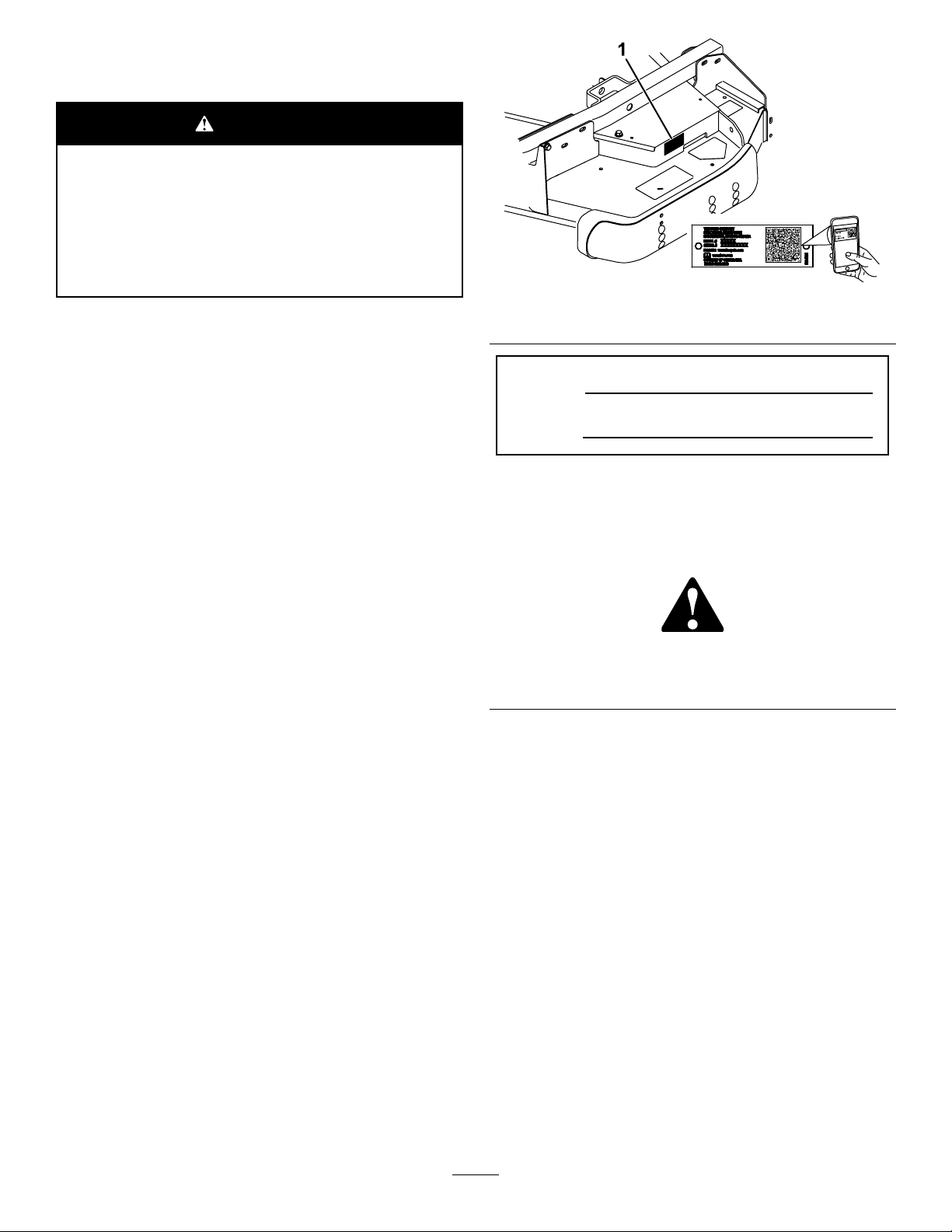
108-1986
1.Heightofcut
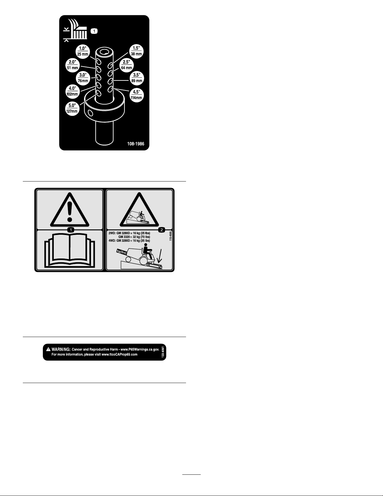
115-4505
1.Warning—readtheOperator'sManual.
2.Tippinghazard—lowerthecuttingunitwhendrivingdown
slopes.For2wheeldriveunits,adda16kg(35lb)rear
weighttoGM3280Dunitsanda32kg(70lb)rearweightto
GM3320units.For4wheeldrive3280Dunits,adda16
kg(35lb)rearweight.
decal108-1986
decal115-4505
decal133-8061
133-8061
6
Page 7

Setup
LooseParts
Usethechartbelowtoverifythatallpartshavebeenshipped.
ProcedureDescription
1
2
3
4
5
6
Nopartsrequired
Completionkit(soldseparately)
Castorwheelassembly
Rightliftarm
Leftliftarm
Pivotpin2
Cotterpin
Thrustwasher4
Clevispin
Hairpincotter2
Height-of-cutcollar
Clevispin
Hairpincotter2
Bolt(1/2x3/4inch)
Washer2
Nopartsrequired
Qty.
–
1Installacompletionkit.
2Installthecastorwheelassemblies.
1
1
2
4
2
2
2
–
Preparethemachine.
Installtheliftarms.
Installthecuttingunits
ConnectthePTOshafttothecutting
unitgearbox.
Use
7
Nopartsrequired
MediaandAdditionalParts
Description
PartsCatalog
Operator'sManual
WARNING
Ifyouleavethekeyintheignitionswitch,
someonecouldaccidentallystarttheengine
andseriouslyinjureyouorotherbystanders.
Removethekeyfromtheignitionswitch
beforeyoudoanymaintenance.
DANGER
IftheengineisstartedandthePTOshaftis
allowedtorotate,seriousinjurycouldresult.
DonotstarttheengineandengagethePTO
leverwhenthePTOshaftisnotconnectedto
thegearboxonthecuttingunit.
Qty.
–
1
1
Readmaterialbeforeoperation
Note:Determinetheleftandrightsidesofthe
machinefromthenormaloperatingposition.
Greasethemachine.
Use
1
PreparingtheMachine
NoPartsRequired
Procedure
1.Parkthemachineonalevelsurface.
2.Engagetheparkingbrake.
3.Shutofftheengineandremovethekey.
7
Page 8
2
InstallingaCompletionKit
Partsneededforthisprocedure:
1
Completionkit(soldseparately)
Procedure
Install1ofthefollowing62-inchor72-inchcompletion
kitstothebasedeckusingtheinstructionprovided
inthekit:
•Model30303,72-inchRearDischarge
•Model30304,72-inchGuardian
•Model30305,62-inchRearDischarge
•Model30306,62-inchGuardian
3
InstallingtheCastorWheel Assemblies
Partsneededforthisprocedure:
2
Castorwheelassembly
Procedure
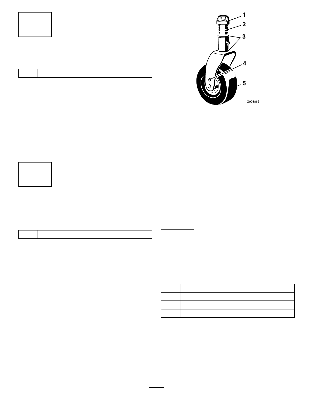
g008866
Figure3
1.Tensioningcap4.Axlemountingholes
2.Spacers5.Castorwheel
3.Thrustwashers
2.Slidethespacersontothecastorspindleto
getthedesiredheight-of-cut;refertoFigure7
andFigure8todeterminethecombinationsof
spacersforthesetting.Slideathrustwasher
ontothespindle,pushthecastorthroughthe
castorarm.Installanotherthrustwasherand
theremainingspacersontothespindleand
installthetensioningcaptosecuretheassembly
(Figure3).
Important:Thethrustwashers,notthe
spacers,mustcontactthetopandbottom
ofthecastorarm.
4
Thethrustwashers,spacers,andtensioningcaps
havebeeninstalledonthecastorwheelspindlesfor
shipping.
1.Removethetensioningcapsfromthespindle
shaftsandslideoffthespacersandthrust
washers(Figure3).
InstallingtheLiftArms
Partsneededforthisprocedure:
1
Rightliftarm
1
Leftliftarm
2Pivotpin
2
Cotterpin
Procedure
1.On1sideofthetractionunit,loosen(donot
remove)thewheelnutssecuringthewheeland
tireassemblytothefrontwheelstuds.
2.Jackupthemachineuntilthefrontwheelisoffof
theoor.Usejackstandsorblockthemachine
topreventitfromaccidentallyfalling.
8
Page 9

3.Removethewheelnutsandslidethewheeland
tireassemblyoffofthestuds.
4.Mountaliftarmtothepivotbracketwithapivot
pinandacotterpin(Figure4).Mounttheliftarm
withthebendpositionedoutward.
Figure4
1.Pivotpin3.Pivotbracket
2.Liftarm
4.Brakereturnspring
5.Hookthebrakereturnspringtothetabonthe
liftarm(Figure4).
2.MovetheliftlevertotheFLOATposition.Push
aliftarmdownuntiltheholesintheliftarmline
upwiththeholesinthecastorarmbracketand
theheightofcutrodcanbeinsertedintothelift
armpads(Figure5).
3.Securetheliftarmtothecastorarmwith2
thrustwashers,aclevispinandahairpincotter.
Positionthethrustwashersbetweentheliftarm
andthecastorarmbracket(Figure5).Insert
endofcotterpinintotheslotinthecastorarm
tabtoretaincotterpin.
g012393
6.Installthewheelandtireassembly.T orquethe
wheelnutsto102to108N·m(75to80ft-lb).
7.Repeattheprocedureontheoppositesideof
themachine.
5
InstallingtheCuttingUnits ontheLiftArms
Partsneededforthisprocedure:
4Thrustwasher
4
Clevispin
2Hairpincotter
2
Height-of-cutcollar
2
Clevispin
2Hairpincotter
2
Bolt(1/2x3/4inch)
2Washer
Figure5
1.Liftarm
2.Castorarmbracket8.Height-of-cutcollar
3.Height-of-cutrod
4.Liftarmpads
5.Thrustwashers11.Bolt
6.Clevispin
7.Hairpincotter
9.Clevispin
10.Hairpincotter
4.Repeattheprocedureontheoppositeliftarm.
g012229
Procedure
1.Movethecuttingunitintopositioninfrontofthe
tractionunit.
5.Startthetractionunitandraisethecuttingunit.
6.Pushdownontherearofthecuttingunitand
inserttheheightofcutrodsthroughtheliftarm
pads.
9
Page 10

7.Installtheheightofcutcollarsontotheheight
ofcutrodsandsecurewiththeclevispinsand
hairpincotters(Figure5).Positiontheheadof
theclevispintowardthefrontofthedeck,if
possible.
8.Installabolt(1/2x3/4inch)andawashertotop
ofeachheightofcutrod(Figure5).
6
ConnectingthePTOShaft totheCuttingUnitGearbox
NoPartsRequired
Procedure
1.SlidethemalePTOshaftintothefemalePTO
shaft(Figure6).Alignthemountingholesinthe
gearcaseinputshaftwiththeholesinthePTO
shaftandslidethemtogether.
7
GreasingtheMachine
NoPartsRequired
Procedure
Beforeoperatingthemachine,itmustbegreasedto
ensureproperlubricatingcharacteristics;referto7
GreasingtheMachine(page10).Failuretoproperly
greasethemachinewillresultinprematurefailureof
criticalparts.
Figure6
1.PTOshaft3.Gearcase
2.Boltsandlocknuts4.Rollpin
2.Securethemwitharollpin(Figure6).
3.Tightentheboltsandnuts(Figure6).
g012230
10
Page 11

ProductOverview
Operation
Specications
Note:Specicationsanddesignaresubjectto
changewithoutnotice.
Width
ofCut
Height
ofCut
Net
Weight
Attachments/Accessories
AselectionofT oroapprovedattachmentsand
accessoriesisavailableforusewiththemachine
toenhanceandexpanditscapabilities.Contact
yourAuthorizedServiceDealerorauthorizedT oro
distributororgotowww.Toro.comforalistofall
approvedattachmentsandaccessories.
Toensureoptimumperformanceandcontinuedsafety
certicationofthemachine,useonlygenuineT oro
replacementpartsandaccessories.Replacement
partsandaccessoriesmadebyothermanufacturers
couldbedangerous,andsuchusecouldvoidthe
productwarranty.
1.575m(62inches)or1.829m(72inches)
Adjustablefrom25to127mm(1to5inches)in13
mm(1/2inch)increments
Model30403–190kg(420lbs.)
Model30404–231kg(510lbs.)
Note:Determinetheleftandrightsidesofthe
machinefromthenormaloperatingposition.
CAUTION
Ifyouleavethekeyintheignitionswitch,
someonecouldaccidentlystarttheengine
andseriouslyinjureyouorotherbystanders.
Removethekeyfromtheignitionbeforeyou
doanymaintenance.
AdjustingtheHeight-of-Cut
Theheight-of-cutisadjustablefrom25to127mm(1
to5inches)in13mm(1/2inch)increments.Toadjust
theheight-of-cut,positionthecastorwheelaxlesin
theupperorlowerholesofthecastorforks,addor
removeanequalnumberofspacersfromthecastor
forksandsecuretheheightofcutcollartothedesired
holesintheheightofcutrod.
1.Starttheengineandraisethecuttingunitoffthe
oorsothatyoucanchangetheheight-of-cut.
Shutofftheengineandremovethekeyafter
youraisethecuttingunit.
2.Positionthecastorwheelaxlesinthesame
holesinbothcastorforks.RefertoFigure7and
Figure8todeterminethecorrectholesforthe
setting.
Note:Whenoperatingin64mm(2–1/2inches)
heightofcutorhigher,installtheaxleboltinthe
lowercastorforkholetopreventgrassbuildup
betweenthewheelandthefork.Whenoperating
inheightofcutslowerthan64mm(2–1/2
inches)andthereisgrassbuildup,reversethe
machinesdirectiontopullanyclippingsaway
fromthewheel/forkarea.
3.Removethetensioningcapfromthespindle
shaft(Figure7)andslidethespindleoutofthe
castorarm.Putthe2shims(1/8inch)ontothe
spindleshaftastheywereoriginallyinstalled.
Theseshimsarerequiredtoachievealevel
acrosstheentirewidthofthecuttingunits.Slide
theappropriatenumberof1/2inchspacersonto
thespindleshafttogetthedesiredheight-of-cut;
thenslidethewasherontotheshaft.
RefertoFigure7andFigure8todeterminethe
combinationsofspacersforthesetting.
11
Page 12

Figure9
g012231
Figure7
1.Tensioningcap4.Axlemountingholes
2.Spacers5.Castorwheel
3.Shims
Figure8
4.Pushthecastorspindlethroughthecastor
arm.Installtheshims(astheywereoriginally
installed)andtheremainingspacersontothe
spindleshaft.Installthetensioningcapto
securetheassembly.
5.Removethehairpinandclevispinsecuringthe
heightofcutcollartotheheightofcutrodonthe
rearofthecuttingunit(Figure9).
1.Height-of-cutrod3.Clevispinandhairpin
g008866
2.Height-of-cutcollar
cotter
6.Aligntheheight-of-cutcollartothedesired
height-of-cutholesontheheight-of-cutrod
(Figure10).
decal100-5622
decal108-1986
Figure10
7.Securetheadjustmentwiththeclevispinand
hairpin.
Note:Positiontheheadoftheclevispintoward
thefrontofthedeck,ifpossible.
Note:Whenusing25mm(1inch),38mm
(1-1/2inch),oroccasionally51mm(2inch)
height-of-cut,movetheskidsandrollertothe
highestholes.
12
Page 13

AdjustingtheCuttingUnit
AdjustingtheSkids
Pitch
Cuttingunitpitchisthedifferenceinheight-of-cutfrom
thefrontofthebladeplanetothebackoftheblade
plane.Useabladepitchof6mm(1/4inch).Thatis
thebackofthebladeplaneis6mm(1/4inch)higher
thanthefront.
1.Parkthemachineonalevelsurface.
2.Engagetheparkingbrake.
3.Shutofftheengineandremovethekey.
4.Setthecuttingunittothedesiredheight-of-cut.
5.Rotate1bladesothatitpointsstraightforward.
6.Usingashortruler,measurefromtheoorto
thefronttipoftheblade.Rotatethebladetipto
therearandmeasurefromtheoortothetip
oftheblade.
7.Subtractthefrontdimensionfromtherear
dimensiontocalculatethebladepitch.
8.Loosenthejamnutsonthebottomofthe
height-of-cutrods(Figure11).
Mounttheskidsinthelowerpositionwhenoperating
inheightofcutshigherthan64mm(2-1/2inches)and
inthehigherpositionwhenoperatinginheightofcuts
lowerthan64mm(2-1/2inches).
Note:Whentheskidsbecomeworn,youcanswitch
theskidtotheoppositesidesofthemower,ipping
themover.Thiswillallowyoutousetheskidslonger
beforereplacingthem.
1.DisengagethePTOandengagetheparking
brake.
2.Shutofftheengine,removethekey,andwait
forallmovingpartstostopbeforeleavingthe
operatingposition.
3.Loosenthescrewatthefrontofeachskid
(Figure12).
4.Removetheange-headboltsandnutsfrom
eachskid.
5.Moveeachskidtothedesiredpositionand
securethemwiththeange-headboltsandnuts
(Figure12).
Note:Onlyusethetoporcentersetsofholes
toadjusttheskids.Thebottomholesareused
whenswitchingsidesonaGuardianmower,at
whichtimetheybecomethetopholesonthe
othersideofthemower.
Figure11
1.Height-of-cut
9.Rotatetheheight-of-cutrodstoraiseorlower
therearofthecuttingunitandattainthecorrect
cuttingunitpitch.
10.Tightenthejamnuts.
2.Jamnut
g012232
g268888
Figure12
1.Screw3.Skid
2.Flange-headbolt4.Nut
6.Torquethescrewatthefrontofeachskidto9to
11N⋅m(80to100in-lb).
13
Page 14

AdjustingtheRollers
Note:Ifthecuttingunitistobeusedinthe25or38
mm(1or1-1/2inch)height-of-cutsetting,positionthe
cuttingunitrollersinthetopbracketholes.
1.Removethescrewandnutsecuringtheroller
shafttothedeckbracket(Figure13).
Figure13
8.Lowercuttingunitontotheatsurface.Remove
thecoversfromthetopofthecuttingunits.
9.Rotatethebladeoneachspindleuntiltheends
faceforwardandbackward.
10.Measurefromtheoortothefronttipofthe
cuttingedge.
11.Adjust1/8inchshimsoncastorfork(s)tomatch
heightofcuttodecal(Figure14);referto
AdjustingtheCuttingUnitPitch(page13).
g004487
1.Roller
2.Slidetheshaftoutofthelowerbracketholes,
aligntherollerwiththetopholes,andinstallthe
shaft.
3.Installthescrewandnuttosecurethe
assemblies.
2.Rollershaft
CorrectingCuttingUnit Mismatch
Duetodifferencesingrassconditionsandthe
counterbalancesettingofthetractionunit,itisadvised
thatgrassbecutandappearancecheckedbefore
formalcuttingisstarted.
1.Setthecuttingunittothedesiredheightofcut;
refertoAdjustingtheHeight-of-Cut(page1 1).
2.Checkandadjustfrontandreartractortire
pressureto172to207kPa(25to30psi).
3.Checkandadjustallcastortirepressuresto345
kPa(50psi).
4.Checkforbentblades;refertoCheckingfora
BentBlade(page20).
5.Cutgrassinatestareatodetermineifallcutting
unitsarecuttingatthesameheight.
6.Ifcuttingunitadjustmentsarestillneeded,nda
atsurfaceusinga2m(6ft)orlongerstraight
edge.
7.Toeasemeasuringbladeplane,raisetheheight
ofcuttothehighestposition;refertoAdjusting
theHeight-of-Cut(page1 1).
g008866
Figure14
1.Tensioningcap4.Axlemountingholes
2.Spacers5.Castorwheel
3.Shims
14
Page 15

OperatingTips
insidethecuttingunit,cuttingqualitywilleventually
becomeunsatisfactory.
FastThrottleSetting/Ground
Speed
Tomaintainenoughpowerforthemachineanddeck
whilemowing,operatetheengineatthefastthrottle
positionandadjustyourgroundspeedforconditions.
Decreasethegroundspeedastheloadonthecutting
bladesincreases.Increasethegroundspeedasthe
loadonthebladesdecreases.
MowingDirection
Alternatemowingdirectiontoavoidmakingrutsin
theturfovertime.Thisalsohelpsdisperseclippings
whichenhancesdecompositionandfertilization.
CuttingSpeed
Toimprovecutquality ,useaslowergroundspeed.
AvoidCuttingTooLow
Ifthecuttingwidthofthecuttingunitiswiderthanthe
moweryoupreviouslyused,raisethecuttingheightto
ensurethatuneventurfisnotcuttooshort.
Toreducetheriskofrehazard,keeptheengine,
mufer,batterycompartment,parkingbrake,cutting
units,andfuelstoragecompartmentfreeofgrass,
leaves,orexcessivegrease.Cleanupanyspilledoil
orfuel.
BladeMaintenance
Maintainasharpbladethroughoutthecuttingseason
becauseasharpbladecutscleanlywithouttearingor
shreddingthegrassblades.Tearingandshredding
turnsgrassbrownattheedges,whichslowsgrowth
andincreasesthechanceofdisease.Checkthe
bladesdailyforsharpness,andforanywearor
damage.Sharpenthebladesasnecessary.Ifablade
isdamagedorworn,replaceitimmediatelywitha
genuineT ororeplacementblade.RefertoServicing
theCuttingBlades(page20).
SettingtheCuttingUnitPitch
Werecommendabladepitchof8mm(5/16inch).A
pitchlargerthan8mm(5/16inch)willresultinless
powerrequired,largerclippings,andapoorerquality
ofcut.Apitchlessthan8mm(5/16inch)willresultin
morepowerrequired,smallerclippingsandabetter
qualityofcut.
SelecttheProperHeight-of-Cut
SettingtoSuitConditions
Removeapproximately1inch(25mm)orno
morethan1/3ofthegrassbladewhencutting.In
exceptionallylushanddensegrass,youmayhave
toslowdowntheforwardspeedand/orraisethe
height-of-cuttothenexthighersetting.
Important:Ifcuttingmorethan1/3ofthe
grassbladeoff,orinsparselonggrassor
dryconditions,theuseofatsailbladesis
recommendedtoreduceair-bornechaff,debris,
anddeckdrivecomponentstrain.
LongGrass
Ifthegrassiseverallowedtogrowslightlylongerthan
normal,orifitcontainsahighdegreeofmoisture,
raisethecuttingheighthigherthanusualandcutthe
grassatthissetting.Thencutthegrassagainusing
thelower,normalsetting.
KeeptheCuttingUnitClean
Cleanclippingsanddirtfromtheundersideofthe
cuttingunitaftereachuse.Ifgrassanddirtbuildup
15
Page 16

Maintenance
Note:Determinetheleftandrightsidesofthe
machinefromthenormaloperatingposition.
RecommendedMaintenanceSchedule(s)
MaintenanceService
Interval
Aftertherst2hours
Aftertherst10hours
Beforeeachuseordaily
Every50hours
Every400hours
DailyMaintenanceChecklist
Duplicatethispageforroutineuse.
MaintenanceProcedure
•Tightenthecastorwheelnuts.
•Tightenthecastorwheelnuts.
•T orquethebladebolts.
•Lubricatethecastorarmbushings.
•Lubricatethecastorwheelbearings.
•Checktheblades.
•Cleanthecuttingunit.
•Lubricatethegreasettings.Lubricatethegreasettingsimmediatelyafterevery
washing.
•Checkthegearboxlubricant.
•Tightenthecastorwheelnuts.
•T orquethebladebolts.
•Checkthebladedrivebeltadjustment.
•Cleanunderthecuttingunitbeltcovers.
•Changethegearboxlubricant.
Fortheweekof: MaintenanceCheckItem
Mon.Tues.Wed.Thurs.Fri.
CheckGrassDeectorin
DownPosition(ifapplicable)
CheckTirePressure
CheckConditionofBlades
LubricateAllGreaseFittings
Touch-upDamagedPaint
1.Immediatelyaftereverywashing,regardlessoftheintervallisted.
NotationforAreasofConcern
Inspectionperformedby:
ItemDate
1
Sat.Sun.
Information
16
Page 17

CAUTION
Ifyouleavethekeyintheignitionswitch,someonecouldaccidentlystarttheengineand
seriouslyinjureyouorotherbystanders.
Removethekeyfromtheignitionbeforeyoudoanymaintenance.
Important:Thefastenersonthecoversofthismachinearedesignedtoremainonthecoverafter
removal.Loosenallthefastenersoneachcoverafewturnssothatthecoverisloosebutstillattached,
thengobackandloosenthemuntilthecovercomesfree.Thispreventsyoufromaccidentallystripping
theboltsfreeoftheretainers.
Lubrication
ServiceInterval:Every50hoursLubricatethe
greasettingsimmediatelyafter
everywashing.
Themachinehasgreasettingsthatyoumust
lubricateregularlywithNo.2lithiumgrease.
Lubricatethefollowingareas:
•Castorforkshaftbushings(4)(Figure15).
Figure17
g012235
Figure15
•Spindleshaftbearings(3)(locatedunderthe
pulley)(Figure16)
1.Liftarm
2.Clevispin
3.Hairpincotter
4.Pivotsupport
•Liftarmpivots,rear(2)(Figure18)
g011557
g010550
Figure18
CheckingtheLubricantin
Figure16
•Idlerarmshaftbearings(Figure16)
•Liftarmpivots,front(2)(Figure17)
theGearbox
ServiceInterval:Every50hours
ThegearboxindesignedtooperateonSAE80–90
g012234
weightgearlube.Althoughthegearboxcomeswith
lubricantfromthefactory,checkthelevelbefore
operatingthecuttingunit.Thegearboxcapacityis
283ml(12oz).
1.Parkthemachineandcuttingunitonalevel
surface.
17
Page 18

2.Removethedipstick/llplugfromthetopof
thegearbox(Figure19)andensurethatthe
lubricantisbetweenthemarksonthedipstick.If
thelubricantlevelislow,addenoughlubricant
untilthelevelisbetweenthemarks.
therearofthecuttingunit(Figure20).Remove
theheightofcutcollar.
4.Removethehairpincottersandclevispins
securingtheliftarmstothecastorarmbrackets
(Figure21).
g012237
Figure21
Figure19
1.Dipstick/llplug
SeparatingtheCuttingUnit fromtheTractionUnit
1.Positionthemachineonlevelsurface,lowerthe
cuttingunittotheoor,movetheliftlevertothe
Floatposition,shuttheengineoff,andengage
theparkingbrake.
2.Removetheboltandwashermountedtothetop
ofeachheightofcutrod(Figure20).
1.Liftarm
g010548
2.Clevispin4.Castorarmbracket
3.Hairpincotter
5.Rollthecuttingunitawayfromthetractionunit,
separatingthemaleandfemalesectionsofthe
PTOshaft(Figure22).
g010552
Figure22
1.PTOshaft
Figure20
1.Height-of-cutrod3.Height-of-cutcollar
2.Boltandwasher4.Hairpincotterandclevis
pin
3.Removethehairpinandclevispinsecuringthe
heightofcutcollartotheheightofcutrodon
DANGER
IftheengineisstartedandthePTOshaft
isallowedtorotate,seriousinjurycould
result.
g012236
18
Donotstarttheengineandengagethe
PTOleverwhenthePTOshaftisnot
connectedtothegearboxonthecutting
unit.
Page 19

MountingtheCuttingUnit totheTractionUnit
1.Positionthemachineonalevelsurfaceandshut
theengineoff.
2.Movethecuttingunitintopositioninfrontofthe
tractionunit.
3.SlidethemalePTOshaftintothefemalePTO
shaft(Figure22).
4.MovetheliftlevertotheFLOA Tposition.Push
aliftarmdownuntiltheholesintheliftarmline
upwiththeholesinthecastorarmbracketand
youcaninserttheheight-of-cutrodintothelift
armpads(Figure23).
andthecastorarmbracket(Figure23).Insert
endofcotterpinintotheslotinthecastorarm
tabtoretaincotterpin.
6.Repeattheprocedureontheoppositeliftarm.
7.Startthetractionunitandraisethecuttingunit.
8.Pushdownontherearofthecuttingunitand
inserttheheightofcutrodsthroughtheliftarm
pads.
9.Installtheheight-of-cutcollarsontothe
height-of-cutrodsandsecurewiththeclevis
pinsandhairpincotters(Figure23).
Positiontheheadoftheclevispintowardthe
frontofthedeck.
10.Installabolt(1/2x3/4inch)andawashertothe
topofeachheight-of-cutrod(Figure23).
ServicingtheBushingsin theCastorArms
Thecastorarmshavebushingspressedintothe
topandbottomofthetube,andaftermanyhours
ofoperation,thebushingswillwear.Tocheckthe
bushings,movethecastorforkbackandforthand
fromsidetoside.Ifthecastorspindleislooseinside
thebushings,thebushingsarewornandmustbe
replaced.
Figure23
1.Liftarm
2.Castorarmbracket8.Height-of-cutcollar
3.Height-of-cutrod9.Clevispin
4.Liftarmpads
5.Thrustwashers11.Bolt
6.Clevispin
5.Securetheliftarmtothecastorarmwith2
thrustwashers,aclevispinandahairpincotter.
Positionthethrustwashersbetweentheliftarm
7.Hairpincotter
10.Hairpincotter
1.Raisethecuttingunitsothatthewheelsare
offoftheoor.Blockthecuttingunitsothatit
cannotaccidentallyfall.
2.Removethetensioningcap,spacer(s),and
thrustwasherfromthetopofthecastorspindle.
3.Pullthecastorspindleoutofthemountingtube.
Allowthethrustwasherandspacer(s)toremain
onthebottomofthespindle.
4.Insertapinpunchintothetoporbottomofthe
mountingtubeanddrivethebushingoutofthe
tube(Figure24).Also,drivetheotherbushing
outofthetube.Cleantheinsideofthetubes
toremovedirt.
g012229
g004737
Figure24
1.Castorarmtube
2.Bushings
19
Page 20

5.Applygreasetotheinsideandoutsideofthe
newbushings.Usingahammerandatplate,
drivethebushingsintothemountingtube.
6.Inspectthecastorspindleforwearandreplace
itifdamaged.
7.Pushthecastorspindlethroughthebushings
andmountingtube,slidethethrustwasher
andspacer(s)ontothespindle,andinstallthe
tensioningcaponthecastorspindle.
ServicingtheCutting Blades
BladeSafety
Awornordamagedbladecanbreak,andapieceof
thebladecouldbethrowntowardyouorbystanders,
resultinginseriouspersonalinjuryordeath.
•Inspectthebladeperiodicallyforwearordamage.
ServicingtheCastor WheelsandBearings
1.Removethelocknutfromtheboltholdingthe
castorwheelassemblybetweenthecastorfork
().Graspthecastorwheelandslidetheboltout
oftheforkorpivotarm.
Figure25
1.Castorwheel3.Bearing(2)
2.Castorfork
2.Removethebearingfromthewheelhuband
allowthebearingspacertofallout().Remove
thebearingfromtheoppositesideofthewheel
hub.
3.Checkthebearings,spacer,andinsideofthe
wheelhubforwear.Replaceanydamaged
parts.
4.T oassemblethecastorwheel,pushthebearing
intothewheelhub.Wheninstallingthebearings,
pressontheouterraceofthebearing.
5.Slidethebearingspacerintothewheelhub.
Pushtheotherbearingintotheopenendofthe
wheelhubtocaptivatethebearingspacerinside
thewheelhub.
6.Installthecastorwheelassemblybetweenthe
castorforkandsecureitinplacewiththebolt
andlocknut.
4.Bearingspacer
•Usecarewhencheckingtheblades.Wrapthe
bladesorweargloves,andusecautionwhen
servicingtheblades.Onlyreplaceorsharpenthe
blades;neverstraightenorweldthem.
•Onmulti-bladedmachines,takecareasrotating1
bladecancauseotherbladestorotate.
CheckingforaBentBlade
1.Positionthemachineonalevelsurface.Raise
thecuttingunit,engagetheparkingbrake,put
thetractionpedalinneutral,putthePTOlever
intheOFFposition,shutofftheengine,and
removetheignitionkey.Blockthecuttingunitto
preventitfromaccidentallyfalling.
2.Rotatethebladeuntiltheendsfaceforward
andbackward.Measurefromtheinsideofthe
cuttingunittothecuttingedgeatthefrontofthe
blade(Figure26),andrememberthisdimension.
g004738
g010549
Figure26
3.Rotatetheoppositeendofthebladeforward.
Measurebetweenthecuttingunitandcutting
edgeofthebladeatthesamepositionasin
step2Thedifferencebetweenthedimensions
obtainedinsteps2and3mustnotexceed3
mm(1/8inch).Ifthedimensionexceeds3mm
(1/8inch),replacethebladebecauseitisbent;
refertoRemovingandInstallingtheBlade(s)
(page20).
RemovingandInstallingthe Blade(s)
Theblademustbereplacedifasolidobjectishit,
thebladeisout-of-balance,worn,orbent.Always
usegenuineT ororeplacementbladestoensure
safetyandoptimumperformance.Neveruseblades
madebyothermanufacturersbecausetheycouldbe
dangerous.
20
Page 21

1.Raisethecuttingunittothehighestposition,
engagetheparkingbrake,stoptheengine,and
removetheignitionkey.Blockthecuttingunitto
preventitfromaccidentallyfalling.
2.Grasptheendofthebladeusingaragorthickly
paddedglove.Removethebladebolt,anti-scalp
cup,andbladefromthespindleshaft(Figure
27).
Figure27
1.Bladebolt2.Anti-scalpcup
goodquality-of-cut.Thesailisimportantbecauseit
pullsgrassupstraight,therebyproducinganeven
cut.However,thesailwillgraduallyweardown
duringoperation,andthisconditionisnormal.As
thesailwearsdown,thequality-of-cutwilldegrade
somewhat,althoughthecuttingedgesaresharp.
Thecuttingedgeoftheblademustbesharpsothat
thegrassiscutratherthantorn.Adullcuttingedge
isevidentwhenthetipsofthegrassappearbrown
andshredded.Sharpenthecuttingedgestocorrect
thiscondition.
1.Parkthemachineonalevelsurface.Raisethe
cuttingunit,engagetheparkingbrake,putthe
tractionpedalinneutral,putthePTOleverinthe
OFFposition,shutofftheengine,andremove
thekey .
2.Examinethecuttingendsofthebladecarefully,
especiallywheretheatandcurvedpartsof
theblademeet(Figure28).Sincesandand
abrasivematerialcanwearawaythemetalthat
g010555
connectstheatandcurvedpartsoftheblade,
checkthebladebeforeusingthemachine.Ifyou
seewear(Figure28),replacetheblade;referto
RemovingandInstallingtheBlade(s)(page20).
3.Installtheblade-sailfacingtowardthecutting
unit-withtheanti-scalpcupandbladebolt.
Tightenthebladeboltto115to149N∙m(85to
110ft-lb).
Important:Thecurvedpartoftheblade
mustpointtowardtheinsideofthecutting
unittoensurepropercutting.
InspectingandSharpeningthe Blade(s)
ServiceInterval:Beforeeachuseordaily
Every50hours
DANGER
Awornordamagedbladecanbreak,anda
pieceofthebladecouldbethrowntowardyou
orbystanders,resultinginseriouspersonal
injuryordeath.
•Inspectthebladeperiodicallyforwearor
damage.
•Donottrytostraightenabladethatisbent.
•Donotweldabrokenorcrackedblade.
•Replaceawornordamagedbladewitha
newTorobladetoensurecontinuedsafety
certicationoftheproduct.
g006530
Figure28
1.Cuttingedge3.Wear/slotforming
2.Curvedarea/sail4.Crack
WARNING
Ifthebladeisallowedtowear,aslot
willformbetweenthesailandatpart
oftheblade(Figure28).Eventually,a
pieceoftheblademaybreakoffandbe
thrownfromunderthehousing,possibly
resultinginseriousinjurytoyourselfor
bystanders.
•Inspectthebladeperiodicallyforwear
ordamage.
•Replaceawornordamagedbladewith
anewTorobladetoensurecontinued
safetycerticationoftheproduct.
Bothcuttingedgesandthesail,whichistheturned
upportionoppositethecuttingedge,contributetoa
3.Examinethecuttingedgesofallblades.
Sharpenthecuttingedgesiftheyaredullor
21
Page 22

nicked.Sharpenonlythetopsideofthecutting
edgeandmaintaintheoriginalcuttingangleto
ensuresharpness(Figure29).Thebladewill
remainbalancedifthesameamountofmetalis
removedfrombothcuttingedges.
Figure29
1.Sharpenatoriginalangle
Note:Removethebladesandsharpenthemon
agrinder;refertoRemovingtheCuttingBlades.
Aftersharpeningthecuttingedges,installthe
bladewiththeanti-scalpcupandbladebolt.The
bladesailsmustbeontopoftheblade.Tighten
thebladeboltto115to149N·m(85to110ft-lb).
CheckingandCorrecting MismatchofBlades
Ifthereismismatchbetweentheblades,thegrasswill
appearstreakedwhenitiscut.Thisproblemcanbe
correctedbymakingsurethatthebladesarestraight
andallofthebladesarecuttingonthesameplane.
1.Usinga1m(3ft)longcarpenterslevel,nda
levelsurfaceontheshopoor.
2.Raisetheheight-of-cuttothehighestposition;
refertoAdjustingtheHeight-of-Cut(page1 1).
3.Lowerthecuttingunitontotheatsurface.
Removethecoversfromthetopofthecutting
unit.
4.Rotatethebladesuntiltheendsfaceforward
andbackward.Measurefromtheoortothe
fronttipofthecuttingedge.Rememberthis
dimension.Thenrotatethesamebladesothat
theoppositeendisforward,andmeasureagain.
Thedifferencebetweenthedimensionsmust
notexceed1m(3ft).Ifthedimensionexceeds
1m(3ft),replacethebladebecauseitisbent.
Measurealloftheblades.
5.Comparethemeasurementsoftheouterblades
withthecenterblade.Thecenterblademust
notbemorethan1m(3ft)lowerthantheouter
blades.Ifthecenterbladeismorethan1m(3
ft)lowerthantheouterblades,proceedtostep
6andaddshimsbetweenthespindlehousing
andthebottomofthecuttingunit.
6.Removethebolts,atwashers,lockwashers,
andnutsfromtheouterspindleinthearea
wheretheshimsmustbeadded.Toraiseor
lowertheblade,addashim,PartNo.3256-24,
betweenthespindlehousingandthebottomof
thecuttingunit.Continuetocheckthealignment
ofthebladesandaddshimsuntilthetipsofthe
bladesarewithintherequireddimension.
Important:Donotusemorethan3shimsat
any1holelocation.Usedecreasingnumbers
ofshimsinadjacentholesifmorethan1
shimisaddedtoany1holelocation.
7.Installthebeltcovers.
g000276
ReplacingtheDriveBelt
Thebladedrivebelt,tensionedbythespringloaded
idlerpulley,isverydurable.However,aftermany
hoursofuse,thebeltwillshowsignsofwear.Signs
ofawornbeltaresquealingwhenbeltisrotating,
bladesslippingwhencuttinggrass,frayededges,
burnmarks,andcracks.Replacethebeltifanyof
theseconditionsoccur.
1.Lowerthecuttingunittotheshopoor.Remove
thebeltcoversfromthetopofthecuttingunit
andsetthecoversaside.
2.Usingatorquewrenchorsimilartool,movethe
idlerpulley(Figure30)awayfromthedrivebelt
toreleasethebelttensionandallowthebeltto
beslippedoffthegearboxpulley(Figure31).
g012238
Figure30
1.Idlerpulley
g012239
Figure31
1.Gearbox
22
Page 23

3.Removetheoldbeltfromaroundthespindle
pulleysandidlerpulley.
Storage
4.Routethenewbeltaroundthespindlepulleys
andidlerpulleyassemblyasshowninFigure32.
Figure32
1.Beltrouting
5.Installthebeltcovers.
CleaningUndertheCutting Unit
ServiceInterval:Beforeeachuseordaily
1.DisengagethePTO,releasethetractionpedal
totheneutralposition,andengagetheparking
brake.
2.Shutofftheengine,removethekey,andwait
forallmovingpartstostopbeforeleavingthe
operator’sposition.
3.Allowtheenginetocoolbeforeadjusting,
cleaning,storing,orrepairingthemachine.
4.Thoroughlycleanthecuttingunit,payingspecial
attentiontotheseareas:
•Underneaththecuttingunit
•Underthecuttingunitbeltcovers
decal108-1988
•PTOshaftassembly
•Allgreasettingsandpivotpoints
5.Checkandadjustthetraction-unitfrontandrear
tirepressure;refertothetraction-unitOperator’s
Manual.
6.Remove,sharpen,andbalancethecuttingunit
blades.Installthebladesandtorquetheblade
fastenersto85to1 10ft-lb(115to149N∙m).
7.Checkallfastenersforloosenessandtighten
themasnecessary.
Removethegrassbuildupunderthecuttingunitdaily .
1.DisengagethePTO,releasethetractionpedal
totheneutralposition,andengagetheparking
brake.
2.MovethethrottlelevertotheSLOWposition,
shutofftheengine,removethekey,andwait
forallmovingpartstostopbeforeleavingthe
operator’sposition.
3.RaisethecuttingunittotheTRANSPORTposition.
4.Useajacktoraisethefrontofthemachineand
supportitwithjackstands.
5.Thoroughlycleantheundersideofthecutting
unitwithwater.
8.Greaseoroilallgreasettingsandpivotpoints.
Wipeoffanyexcesslubricant.
9.Lightlysandandusetouchuppaintonpainted
areasthatarescratched,chippedorrusted.
Repairanydents.
23
Page 24

Notes:
Page 25

DeclarationofIncorporation
TheT oroCompany,8111LyndaleAve.South,Bloomington,MN,USAdeclaresthatthefollowingunit(s)
conform(s)tothedirectiveslisted,wheninstalledinaccordancewiththeaccompanyinginstructionsontocertain
ToromodelsasindicatedontherelevantDeclarationsofConformity.
ModelNo.
30403315000001andUpBase62inMower
30404315000001andUpBase72inMower
SerialNo.
ProductDescriptionInvoiceDescription
GeneralDescription
62”BASEDECK-GM3280
72”BASEDECK-GM3280
Base62inMower
Base72inMower
Directive
2006/42/EC,
2000/14/EC
2006/42/EC,
2000/14/EC
RelevanttechnicaldocumentationhasbeencompiledasrequiredperPartBofAnnexVIIof2006/42/EC.
Wewillundertaketotransmit,inresponsetorequestsbynationalauthorities,relevantinformationonthispartly
completedmachinery.Themethodoftransmissionshallbeelectronictransmittal.
ThismachineryshallnotbeputintoserviceuntilincorporatedintoapprovedT oromodelsasindicatedonthe
associatedDeclarationofConformityandinaccordancewithallinstructions,wherebyitcanbedeclaredin
conformitywithallrelevantDirectives.
Certied:
JohnHeckel
Sr.EngineeringManager
811 1LyndaleAve.South
Bloomington,MN55420,USA
September20,2018
AuthorizedRepresentative:
MarcelDutrieux
ManagerEuropeanProductIntegrity
ToroEuropeNV
Nijverheidsstraat5
2260Oevel
Belgium
Tel.+3216386659
Page 26

CaliforniaProposition65WarningInformation
Whatisthiswarning?
Youmayseeaproductforsalethathasawarninglabellikethefollowing:
WARNING:CancerandReproductiveHarm—www.p65Warnings.ca.gov.
WhatisProp65?
Prop65appliestoanycompanyoperatinginCalifornia,sellingproductsinCalifornia,ormanufacturingproductsthatmaybesoldinorbroughtinto
California.ItmandatesthattheGovernorofCaliforniamaintainandpublishalistofchemicalsknowntocausecancer,birthdefects,and/orother
reproductiveharm.Thelist,whichisupdatedannually,includeshundredsofchemicalsfoundinmanyeverydayitems.ThepurposeofProp65isto
informthepublicaboutexposuretothesechemicals.
Prop65doesnotbanthesaleofproductscontainingthesechemicalsbutinsteadrequireswarningsonanyproduct,productpackaging,orliteraturewith
theproduct.Moreover,aProp65warningdoesnotmeanthataproductisinviolationofanyproductsafetystandardsorrequirements.Infact,the
CaliforniagovernmenthasclariedthataProp65warning“isnotthesameasaregulatorydecisionthataproductis‘safe’or‘unsafe.’”Manyofthese
chemicalshavebeenusedineverydayproductsforyearswithoutdocumentedharm.Formoreinformation,gotohttps://oag.ca.gov/prop65/faqs-view-all
AProp65warningmeansthatacompanyhaseither(1)evaluatedtheexposureandhasconcludedthatitexceedsthe“nosignicantrisklevel”;or(2)
haschosentoprovideawarningbasedonitsunderstandingaboutthepresenceofalistedchemicalwithoutattemptingtoevaluatetheexposure.
Doesthislawapplyeverywhere?
Prop65warningsarerequiredunderCalifornialawonly.ThesewarningsareseenthroughoutCaliforniainawiderangeofsettings,includingbutnot
limitedtorestaurants,grocerystores,hotels,schools,andhospitals,andonawidevarietyofproducts.Additionally,someonlineandmailorder
retailersprovideProp65warningsontheirwebsitesorincatalogs.
.
HowdotheCaliforniawarningscomparetofederallimits?
Prop65standardsareoftenmorestringentthanfederalandinternationalstandards.TherearevarioussubstancesthatrequireaProp65warning
atlevelsthatarefarlowerthanfederalactionlimits.Forexample,theProp65standardforwarningsforleadis0.5μg/day,whichiswellbelow
thefederalandinternationalstandards.
Whydon’tallsimilarproductscarrythewarning?
•ProductssoldinCaliforniarequireProp65labellingwhilesimilarproductssoldelsewheredonot.
•AcompanyinvolvedinaProp65lawsuitreachingasettlementmayberequiredtouseProp65warningsforitsproducts,butothercompanies
makingsimilarproductsmayhavenosuchrequirement.
•TheenforcementofProp65isinconsistent.
•CompaniesmayelectnottoprovidewarningsbecausetheyconcludethattheyarenotrequiredtodosounderProp65;alackofwarningsfora
productdoesnotmeanthattheproductisfreeoflistedchemicalsatsimilarlevels.
WhydoesToroincludethiswarning?
Torohaschosentoprovideconsumerswithasmuchinformationaspossiblesothattheycanmakeinformeddecisionsabouttheproductstheybuyand
use.T oroprovideswarningsincertaincasesbasedonitsknowledgeofthepresenceofoneormorelistedchemicalswithoutevaluatingthelevelof
exposure,asnotallthelistedchemicalsprovideexposurelimitrequirements.WhiletheexposurefromToroproductsmaybenegligibleorwellwithinthe
“nosignicantrisk”range,outofanabundanceofcaution,TorohaselectedtoprovidetheProp65warnings.Moreover ,ifT orodoesnotprovidethese
warnings,itcouldbesuedbytheStateofCaliforniaorbyprivatepartiesseekingtoenforceProp65andsubjecttosubstantialpenalties.
RevA
Page 27

EEA/UKPrivacyNotice
Toro’sUseofY ourPersonalInformation
TheT oroCompany(“T oro”)respectsyourprivacy.Whenyoupurchaseourproducts,wemaycollectcertainpersonalinformationaboutyou,eitherdirectly
fromyouorthroughyourlocalT orocompanyordealer.T orousesthisinformationtofullcontractualobligations-suchastoregisteryourwarranty,
processyourwarrantyclaimortocontactyouintheeventofaproductrecall-andforlegitimatebusinesspurposes-suchastogaugecustomer
satisfaction,improveourproductsorprovideyouwithproductinformationwhichmaybeofinterest.Toromayshareyourinformationwithoursubsidiaries,
afliates,dealersorotherbusinesspartnersinconnectiontheseactivities.Wemayalsodisclosepersonalinformationwhenrequiredbylaworin
connectionwiththesale,purchaseormergerofabusiness.Wewillneversellyourpersonalinformationtoanyothercompanyformarketingpurposes.
RetentionofyourPersonalInformation
Torowillkeepyourpersonalinformationaslongasitisrelevantfortheabovepurposesandinaccordancewithlegalrequirements.Formoreinformation
aboutapplicableretentionperiodspleasecontactlegal@toro.com.
Toro’sCommitmenttoSecurity
YourpersonalinformationmaybeprocessedintheUSoranothercountrywhichmayhavelessstrictdataprotectionlawsthanyourcountryofresidence.
Wheneverwetransferyourinformationoutsideofyourcountryofresidence,wewilltakelegallyrequiredstepstoensurethatappropriatesafeguardsare
inplacetoprotectyourinformationandtomakesureitistreatedsecurely.
AccessandCorrection
Youmayhavetherighttocorrectorreviewyourpersonaldata,orobjecttoorrestricttheprocessingofyourdata.T odoso,pleasecontactusbyemail
atlegal@toro.com.IfyouhaveconcernsaboutthewayinwhichT orohashandledyourinformation,weencourageyoutoraisethisdirectlywithus.
PleasenotethatEuropeanresidentshavetherighttocomplaintoyourDataProtectionAuthority.
374-0282RevC
Page 28

TheToroWarranty
ATwo-YearLimitedWarranty
ConditionsandProductsCovered
TheToroCompanyanditsafliate,ToroWarrantyCompany,pursuant
toanagreementbetweenthem,jointlywarrantyourT oroCommercial
product(“Product”)tobefreefromdefectsinmaterialsorworkmanship
fortwoyearsor1500operationalhours*,whicheveroccursrst.This
warrantyisapplicabletoallproductswiththeexceptionofAerators
(refertoseparatewarrantystatementsfortheseproducts).Wherea
warrantableconditionexists,wewillrepairtheProductatnocosttoyou
includingdiagnostics,labor,parts,andtransportation.Thiswarranty
beginsonthedatetheProductisdeliveredtotheoriginalretailpurchaser.
*Productequippedwithanhourmeter.
InstructionsforObtainingWarrantyService
YouareresponsiblefornotifyingtheCommercialProductsDistributoror
AuthorizedCommercialProductsDealerfromwhomyoupurchasedthe
Productassoonasyoubelieveawarrantableconditionexists.Ifyouneed
helplocatingaCommercialProductsDistributororAuthorizedDealer,or
ifyouhavequestionsregardingyourwarrantyrightsorresponsibilities,
youmaycontactusat:
ToroCommercialProductsServiceDepartment
ToroWarrantyCompany
811 1LyndaleAvenueSouth
Bloomington,MN55420-1196
952–888–8801or800–952–2740
E-mail:commercial.warranty@toro.com
OwnerResponsibilities
AstheProductowner,youareresponsibleforrequiredmaintenanceand
adjustmentsstatedinyourOperator'sManual.Failuretoperformrequired
maintenanceandadjustmentscanbegroundsfordisallowingawarranty
claim.
ItemsandConditionsNotCovered
Notallproductfailuresormalfunctionsthatoccurduringthewarranty
periodaredefectsinmaterialsorworkmanship.Thiswarrantydoesnot
coverthefollowing:
•Productfailureswhichresultfromtheuseofnon-T ororeplacement
parts,orfrominstallationanduseofadd-on,ormodiednon-Toro
brandedaccessoriesandproducts.Aseparatewarrantymaybe
providedbythemanufactureroftheseitems.
•Productfailureswhichresultfromfailuretoperformrecommended
maintenanceand/oradjustments.Failuretoproperlymaintainyour
ToroproductpertheRecommendedMaintenancelistedinthe
Operator’sManualcanresultinclaimsforwarrantybeingdenied.
•ProductfailureswhichresultfromoperatingtheProductinanabusive,
negligent,orrecklessmanner.
•Partssubjecttoconsumptionthroughuseunlessfoundtobedefective.
Examplesofpartswhichareconsumed,orusedup,duringnormal
Productoperationinclude,butarenotlimitedto,brakepadsand
linings,clutchlinings,blades,reels,rollersandbearings(sealedor
greasable),bedknives,sparkplugs,castorwheelsandbearings,tires,
lters,belts,andcertainsprayercomponentssuchasdiaphragms,
nozzles,andcheckvalves,etc.
•Failurescausedbyoutsideinuence.Conditionsconsideredtobe
outsideinuenceinclude,butarenotlimitedto,weather,storage
practices,contamination,useofunapprovedfuels,coolants,lubricants,
additives,fertilizers,water,orchemicals,etc.
•Failureorperformanceissuesduetotheuseoffuels(e.g.gasoline,
diesel,orbiodiesel)thatdonotconformtotheirrespectiveindustry
standards.
•Normalnoise,vibration,wearandtear,anddeterioration.
•Normal“wearandtear”includes,butisnotlimitedto,damagetoseats
duetowearorabrasion,wornpaintedsurfaces,scratcheddecalsor
windows,etc.
Parts
Partsscheduledforreplacementasrequiredmaintenancearewarranted
fortheperiodoftimeuptothescheduledreplacementtimeforthatpart.
Partsreplacedunderthiswarrantyarecoveredforthedurationofthe
originalproductwarrantyandbecomethepropertyofT oro.Torowillmake
thenaldecisionwhethertorepairanyexistingpartorassemblyorreplace
it.T oromayuseremanufacturedpartsforwarrantyrepairs.
DeepCycleandLithium-IonBatteryWarranty:
DeepcycleandLithium-Ionbatterieshaveaspeciedtotalnumberof
kilowatt-hourstheycandeliverduringtheirlifetime.Operating,recharging,
andmaintenancetechniquescanextendorreducetotalbatterylife.Asthe
batteriesinthisproductareconsumed,theamountofusefulworkbetween
chargingintervalswillslowlydecreaseuntilthebatteryiscompletelyworn
out.Replacementofwornoutbatteries,duetonormalconsumption,
istheresponsibilityoftheproductowner.Batteryreplacementmaybe
requiredduringthenormalproductwarrantyperiodatowner’sexpense.
Note:(Lithium-Ionbatteryonly):ALithium-Ionbatteryhasapartonly
proratedwarrantybeginningyear3throughyear5basedonthetime
inserviceandkilowatthoursused.RefertotheOperator'sManualfor
additionalinformation.
MaintenanceisatOwner’sExpense
Enginetune-up,lubrication,cleaningandpolishing,replacementoflters,
coolant,andcompletingrecommendedmaintenancearesomeofthe
normalservicesT oroproductsrequirethatareattheowner’sexpense.
GeneralConditions
RepairbyanAuthorizedToroDistributororDealerisyoursoleremedy
underthiswarranty.
NeitherTheToroCompanynorToroWarrantyCompanyisliablefor
indirect,incidentalorconsequentialdamagesinconnectionwiththe
useoftheToroProductscoveredbythiswarranty,includingany
costorexpenseofprovidingsubstituteequipmentorserviceduring
reasonableperiodsofmalfunctionornon-usependingcompletion
ofrepairsunderthiswarranty.ExceptfortheEmissionswarranty
referencedbelow,ifapplicable,thereisnootherexpresswarranty.All
impliedwarrantiesofmerchantabilityandtnessforusearelimitedto
thedurationofthisexpresswarranty.
Somestatesdonotallowexclusionsofincidentalorconsequential
damages,orlimitationsonhowlonganimpliedwarrantylasts,sotheabove
exclusionsandlimitationsmaynotapplytoyou.Thiswarrantygivesyou
speciclegalrights,andyoumayalsohaveotherrightswhichvaryfrom
statetostate.
Noteregardingenginewarranty:
TheEmissionsControlSystemonyourProductmaybecoveredby
aseparatewarrantymeetingrequirementsestablishedbytheU.S.
EnvironmentalProtectionAgency(EP A)and/ortheCaliforniaAirResources
Board(CARB).Thehourlimitationssetforthabovedonotapplytothe
EmissionsControlSystemWarranty.RefertotheEngineEmissionControl
WarrantyStatementsuppliedwithyourproductorcontainedintheengine
manufacturer’sdocumentationfordetails
CountriesOtherthantheUnitedStatesorCanada
CustomerswhohavepurchasedT oroproductsexportedfromtheUnitedStatesorCanadashouldcontacttheirT oroDistributor(Dealer)toobtain
guaranteepoliciesforyourcountry ,province,orstate.IfforanyreasonyouaredissatisedwithyourDistributor'sserviceorhavedifcultyobtaining
guaranteeinformation,contacttheT oroimporter.
374-0253RevD
 Loading...