

Page 1

Base62inand72inMower
FormNo.3383-247RevA
Groundsmaster
ModelNo.30403—SerialNo.314000001andUp
ModelNo.30404—SerialNo.314000001andUp
®
3320/3280-DTractionUnit
Registeratwww.T oro.com.
OriginalInstructions(EN)
*3383-247*A
Page 2

WARNING
CALIFORNIA
Proposition65Warning
Thisproductcontainsachemicalorchemicals
knowntotheStateofCaliforniatocausecancer,
birthdefects,orreproductiveharm.
Introduction
ThisproductcomplieswithallrelevantEuropeandirectives,
fordetailspleaseseetheseparateproductspecicDeclaration
ofConformity(DOC)sheet.
Thisrotary-bladelawncuttingdeckismountedtoaride-on
machineandisintendedtobeusedbyprofessional,hired
operatorsincommercialapplications.Itisprimarilydesigned
forcuttinggrassonwell-maintainedlawnsinparks,sports
elds,andoncommercialgrounds.Itisnotdesignedfor
cuttingbrush,mowinggrassandothergrowthalongside
highways,orforagriculturaluses.
Figure1
1.Safetyalertsymbol
Thismanualuses2otherwordstohighlightinformation.
Importantcallsattentiontospecialmechanicalinformation
andNoteemphasizesgeneralinformationworthyofspecial
attention.
Readthisinformationcarefullytolearnhowtooperateand
maintainyourproductproperlyandtoavoidinjuryand
productdamage.Youareresponsibleforoperatingthe
productproperlyandsafely.
YoumaycontactTorodirectlyatwww .Toro.comforproduct
andaccessoryinformation,helpndingadealer,ortoregister
yourproduct.
Wheneveryouneedservice,genuineT oroparts,oradditional
information,contactanAuthorizedServiceDealerorToro
CustomerServiceandhavethemodelandserialnumbers
ofyourproductready .Themodelandserialnumbersare
stampedintoaplatethatismountedonthemowerhousing.
Writethenumbersinthespaceprovided.
ModelNo.
SerialNo.
Thismanualidentiespotentialhazardsandhassafety
messagesidentiedbythesafetyalertsymbol(Figure1),
whichsignalsahazardthatmaycauseseriousinjuryordeath
ifyoudonotfollowtherecommendedprecautions.
©2014—TheToro®Company
8111LyndaleAvenueSouth
Bloomington,MN55420
Contactusatwww.Toro.com.
2
PrintedintheUSA.
AllRightsReserved
Page 3

Contents
Safety
Introduction..................................................................2
Safety...........................................................................3
SafeOperatingPractices...........................................3
ToroMowerSafety..................................................5
SafetyandInstructionalDecals.................................6
Setup............................................................................8
1InstallingaCompletionKit....................................8
2InstallingtheCastorWheelAssemblies....................8
3InstallingtheLiftArms..........................................9
4InstallingtheCuttingUnitsontheLift
Arms.................................................................9
5ConnectingthePTOShafttotheCuttingUnit
GearBox...........................................................10
6GreasingtheMachine...........................................11
ProductOverview.........................................................11
Specications........................................................11
Attachments/Accessories........................................11
Operation....................................................................12
CheckingtheLubricantintheGearBox.....................12
AdjustingtheHeight-of-Cut....................................12
AdjustingtheCuttingUnitPitch...............................13
AdjustingtheSkids.................................................13
AdjustingtheRollers...............................................14
CorrectingCuttingUnitMismatch............................14
OperatingTips......................................................14
Maintenance.................................................................16
RecommendedMaintenanceSchedule(s)......................16
Lubrication............................................................16
SeparatingtheCuttingUnitfromtheTraction
Unit..................................................................17
MountingtheCuttingUnittotheTraction
Unit..................................................................18
ServicingtheBushingsintheCastorArms.................19
ServicingtheCastorWheelsandBearings..................19
CheckingforaBentBlade........................................19
RemovingandInstallingtheBlade(s).........................20
InspectingandSharpeningtheBlade(s)......................20
CheckingandCorrectingMismatchof
Blades...............................................................21
ReplacingtheDriveBelt..........................................21
ThismachinemeetsorexceedsCENstandardEN836:1997,
ISOstandard5395:1990,andANSIB71.4-2004specications
ineffectatthetimeofproduction,whenequippedwith
properballast.Refertothetractionunitoperatorsmanual
fortheballastrequirements.
Improperuseormaintenancebytheoperatororownercan
resultininjury.Toreducethepotentialforinjury,comply
withthesesafetyinstructionsandalwayspayattentiontothe
safetyalertsymbol,whichmeansCAUTION,WARNING,or
DANGER-"personalsafetyinstruction."Failuretocomply
withtheinstructionmayresultinpersonalinjuryordeath.
SafeOperatingPractices
ThefollowinginstructionsareadaptedfromtheCEN
standardEN836:1997,ISOstandard5395:1990,andANSI
B71.4-2012.
Training
•Readtheoperator'smanualandothertrainingmaterial
carefully.Befamiliarwiththecontrols,safetysigns,and
theproperuseoftheequipment.Iftheoperatoror
mechaniccannotreadthelanguageofthismanual,itis
theowner'sresponsibilitytoexplainthismaterialtothem.
•Becomefamiliarwiththesafeoperationoftheequipment,
operatorcontrols,andsafetysigns.
•Alloperatorsandmechanicsshouldbetrained.The
ownerisresponsiblefortrainingtheusers
•Neverletchildrenoruntrainedpeopleoperateorservice
theequipment.Localregulationsmayrestricttheageof
theoperator.
•Theowner/usercanpreventandisresponsiblefor
accidentsorinjuriesoccurringtohimselforherself,other
people,orproperty.
Preparation
•Evaluatetheterraintodeterminewhataccessoriesand
attachmentsareneededtoproperlyandsafelyperform
thejob.Onlyuseaccessoriesandattachmentsapproved
bythemanufacturer.
•Wearappropriateclothingincludinghardhat,safety
glassesandearprotection.Longhair,looseclothingor
jewelrymaygettangledinmovingparts.
•Inspecttheareawheretheequipmentistobeusedand
removeallobjectssuchasrocks,toysandwirewhichcan
bethrownbythemachine.
•Checkthatoperator'spresencecontrols,safetyswitches
andshieldsareattachedandfunctioningproperly .Donot
operateunlesstheyarefunctioningproperly.
3
Page 4

SafeHandlingofFuels
•Toavoidpersonalinjuryorpropertydamage,use
extremecareinhandlinggasoline.Gasolineisextremely
ammableandthevaporsareexplosive.
•Extinguishallcigarettes,cigars,pipes,andothersources
ofignition.
•Useonlyanapprovedfuelcontainer.
•Neverremovefuelcaporaddfuelwiththeengine
running.
•Allowenginetocoolbeforerefueling.
•Neverrefuelthemachineindoors.
•Neverstorethemachineorfuelcontainerwherethereis
anopename,spark,orpilotlightsuchasonawater
heateroronotherappliances.
•Neverllcontainersinsideavehicleoronatruckor
trailerbedwithaplasticliner.Alwaysplacecontainerson
thegroundawayfromyourvehiclebeforelling.
•Removeequipmentfromthetruckortrailerandrefuelit
ontheground.Ifthisisnotpossible,thenrefuelsuch
equipmentwithaportablecontainer,ratherthanfroma
fueldispensernozzle.
•Keepthenozzleincontactwiththerimofthefueltank
orcontaineropeningatalltimesuntilfuelingiscomplete.
Donotuseanozzlelockopendevice.
•Iffuelisspilledonclothing,changeclothingimmediately.
•Neveroverllfueltank.Replacefuelcapandtighten
securely.
Operation
•Neverrunanengineinanenclosedarea.
•Onlyoperateingoodlight,keepingawayfromholesand
hiddenhazards.
•Besurealldrivesareinneutralandparkingbrakeis
engagedbeforestartingengine.Onlystartenginefrom
theoperator'sposition.Useseatbeltsifprovided.
•Slowdownanduseextracareonhillsides.Besureto
travelintherecommendeddirectiononhillsides.Turf
conditionscanaffectthemachine'sstability .Usecaution
whileoperatingneardrop-offs.
•Slowdownandusecautionwhenmakingturnsandwhen
changingdirectionsonslopes.
•Neverraisedeckwiththebladesrunning.
•Neveroperatewithguardsnotsecurelyinplace.Be
sureallinterlocksareattached,adjustedproperly ,and
functioningproperty.
•Donotchangetheenginegovernorsettingoroverspeed
theengine.
•Stoponlevelground,lowerthecuttingunits,disengage
drives,engageparkingbrake(ifprovided),shutoffengine
beforeleavingtheoperator'spositionforanyreason.
•Stopequipmentandinspectthebladesafterstriking
objectsorifanabnormalvibrationoccurs.Make
necessaryrepairsbeforeresumingoperations.
•Keephandsandfeetawayfromthecuttingunits.
•Lookbehindanddownbeforebackinguptobesureof
aclearpath.
•Nevercarrypassengersandkeeppetsandbystanders
away.
•Slowdownandusecautionwhenmakingturnsand
crossingroadsandsidewalks.Stopbladesifnotmowing.
•Donotoperatethemowerundertheinuenceofalcohol
ordrugs.
•Lightningcancausesevereinjuryordeath.Iflightning
isseenorthunderisheardinthearea,donotoperate
themachine;seekshelter.
•Usecarewhenloadingorunloadingthemachineintoa
trailerortruck.
•Usecarewhenapproachingblindcorners,shrubs,trees,
orotherobjectsthatmayobscurevision.
•Theoperatorshallturnonashingwarninglights,if
provided,whenevertravelingonapublicroad,except
wheresuchuseisprohibitedbylaw.
MaintenanceandStorage
•Disengagedrives,lowerthecuttingunits,movetraction
pedaltoNeutral,setparkingbrake,stopengineand
removekey .Waitforallmovementtostopbefore
adjusting,cleaningorrepairing.
•Cleangrassanddebrisfromcuttingunits,drives,and
mufer.Cleanupoilorfuelspillage.
•Letenginecoolbeforestoringanddonotstorenear
ame.
•Shutofffuelwhilestoringortransporting.Donotstore
fuelnearamesordrainindoors.
•Parkmachineonlevelground.Neverallowuntrained
personneltoservicemachine.
•Usejackstandstosupportcomponentswhenrequired.
•Carefullyreleasepressurefromcomponentswithstored
energy.
•Disconnectbatterybeforemakinganyrepairs.Disconnect
thenegativeterminalrstandthepositivelast.Reconnect
positiverstandnegativelast.
•Usecarewhencheckingblades.Wrapthebladesor
weargloves,andusecautionwhenservicingthem.Only
replaceblades.Neverstraightenorweldthem.
•Keephandsandfeetawayfrommovingparts.Ifpossible,
donotmakeadjustmentswiththeenginerunning.
•Chargebatteriesinanopenwellventilatedarea,away
fromsparkandames.Unplugchargerbeforeconnecting
ordisconnectingfrombattery.W earprotectiveclothing
anduseinsulatedtools.
•Keepallpartsingoodworkingconditionandallhardware
tightened.Replaceallwornordamageddecals.
4
Page 5

Hauling
•Usecarewhenloadingorunloadingthemachineintoa
trailerortruck.
•Usefullwidthrampsforloadingmachineintotraileror
truck.
•Tiethemachinedownsecurelyusingstraps,chains,cable,
orropes.Bothfrontandrearstrapsshouldbedirected
downandoutwardfromthemachine
•Makesurethatallhydrauliclineconnectorsaretightand
allhydraulichosesandlinesareingoodconditionbefore
applyingpressuretothesystem.
•Keepyourbodyandhandsawayfrompinholeleaksor
nozzlesthatejecthydraulicuidunderhighpressure.
Usepaperorcardboard,notyourhands,tosearchfor
leaks.Hydraulicuidescapingunderpressurecanhave
sufcientforcetopenetratetheskinandcauseserious
injury.
ToroMowerSafety
ThefollowinglistcontainssafetyinformationspecictoToro
productsorothersafetyinformationthatyoumustknowthat
isnotincludedintheCEN,ISO,orANSIstandards.
Thisproductiscapableofamputatinghandsandfeetand
throwingobjects.Alwaysfollowallsafetyinstructionsto
avoidseriousinjuryordeath.
Useofthisproductforpurposesotherthanitsintendeduse
couldprovedangeroustouserandbystanders.
•Knowhowtostoptheenginequickly.
•Donotoperatethemachinewhilewearingtennisshoes
orsneakers.
•Wearingsafetyshoesandlongpantsisadvisableand
requiredbysomelocalordinancesandinsurance
regulations.
•Handlefuelcarefully.Wipeupanyspills.
•Checkthesafetyinterlockswitchesdailyforproper
operation.Ifaswitchshouldfail,replacetheswitch
beforeoperatingthemachine.
•Usingthemachinedemandsattention.Topreventloss
ofcontrol:
–Donotdriveclosetosandtraps,ditches,creeks,
embankments,orotherhazards.
–Avoidsuddenstopsandstarts.
–Whennearorcrossingroads,alwaysyieldthe
right-of-way.
–Lowerthecuttingunitwhengoingdownslopes.
•Thegrassdeectormustalwaysbeinstalledandinthe
lowestpositiononthesidedischargecuttingunit.Never
operatethemowerwithoutthedeectororentiregrass
collector.
•Ifthecuttingunitdischargeareaeverplugs,shutthe
engineoffbeforeremovingtheobstruction.
•Cutgrassslopescarefully.Donotstart,stop,orturn
suddenly.
•Donottouchtheengineormuferwhiletheengineis
runningorsoonafterithasstoppedbecausetheseareas
couldbehotenoughtocauseburns.
•Beforedisconnectingorperforminganyworkonthe
hydraulicsystem,allpressureinthesystemmustbe
relievedbystoppingtheengineandloweringthecutting
unitstotheground.
•Iftheenginemustberunningtoperformamaintenance
adjustment,keephands,feet,clothing,andanypartsof
thebodyawayfromthecuttingunits,attachments,and
anymovingparts.Keepeveryoneaway.
•Donotoverspeedtheenginebychanginggovernor
settings.Toensuresafetyandaccuracy,havean
AuthorizedToroDistributorcheckthemaximumengine
speedwithatachometer.
•Theenginemustbeshutoffbeforecheckingtheoilor
addingoiltothecrankcase.
•Makesurethatthemowerfueltankisemptyifthe
machineistobestoredinexcessof30days.Donotstore
themowernearanyopenameorwheregasolinefumes
maybeignitedbyaspark.
•Performonlythosemaintenanceinstructionsdescribed
inthismanual.Ifmajorrepairsareeverneededor
ifassistanceisdesired,contactanAuthorizedToro
Distributor.
•Tomakesureofoptimumperformanceandcontinued
safetycerticationofthemachine,useonlygenuineToro
replacementpartsandaccessories.Replacementparts
andaccessoriesmadebyothermanufacturerscouldbe
dangerous,andsuchusecouldvoidtheproductwarranty.
MaintenanceandStorage
•Checktheblademountingboltsfrequentlytobesurethat
theyaretightenedtospecication.
5
Page 6
SafetyandInstructionalDecals
Safetydecalsandinstructionsareeasilyvisibletotheoperatorandarelocatednearanyareaofpotential
danger.Replaceanydecalthatisdamagedorlost.
117–4979
1.Entanglementhazard,belt—stayawayfrommovingparts,
keepallguardsandshieldsinplace.
120-6604
1.Thrownobjecthazard—keepbystandersawayfromthe
machine.
2.Cutting/dismembermenthazardofhand,mower
blade—stayawayfrommovingparts,keepallguardsand
shieldsinplace.
3.Cutting/dismembermenthazardoffoot,mowerblade—stay
awayfrommovingparts,keepallguardsandshieldsin
place.
93-6697
1.ReadtheOperator's
Manual.
2.AddSAE80w-90(API
GL-5)oilevery50hours.
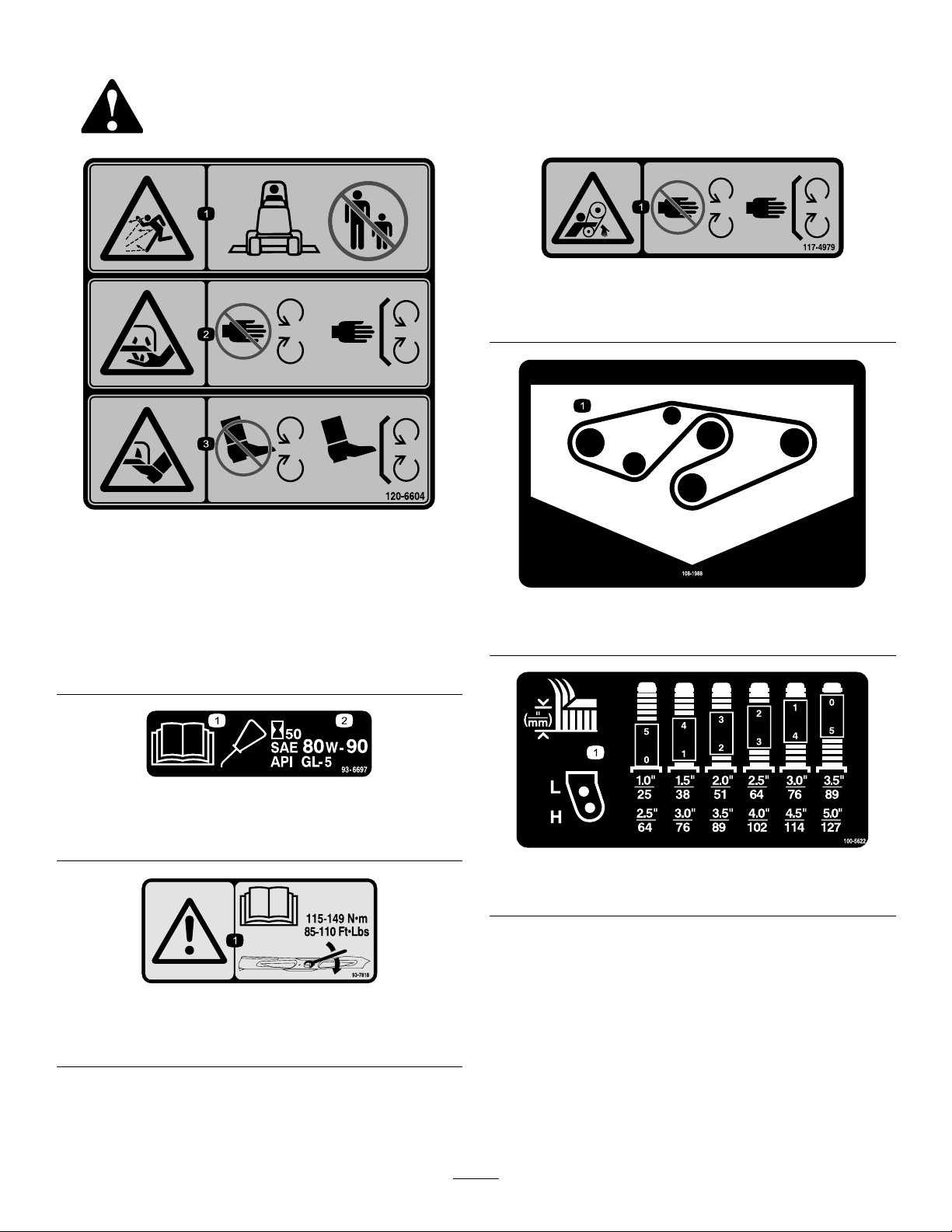
108-1988
1.Beltrouting
100-5622
1.Heightofcutadjustment
93-7818
1.Warning—readtheOperator'sManualforinstructionson
torquingthebladebolt/nutto115-149N-m(85-110ft-lb).
6
Page 7
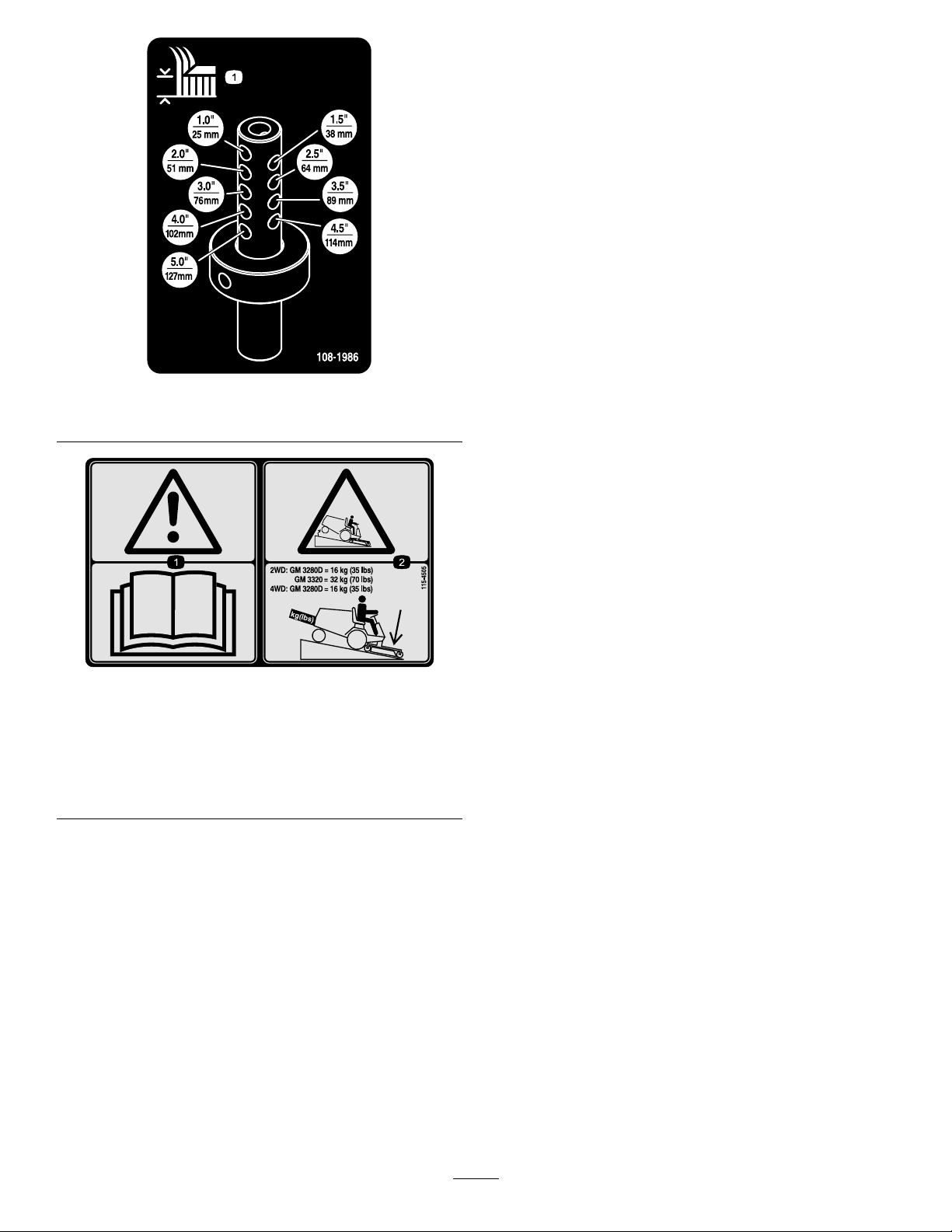
108-1986
1.Heightofcut
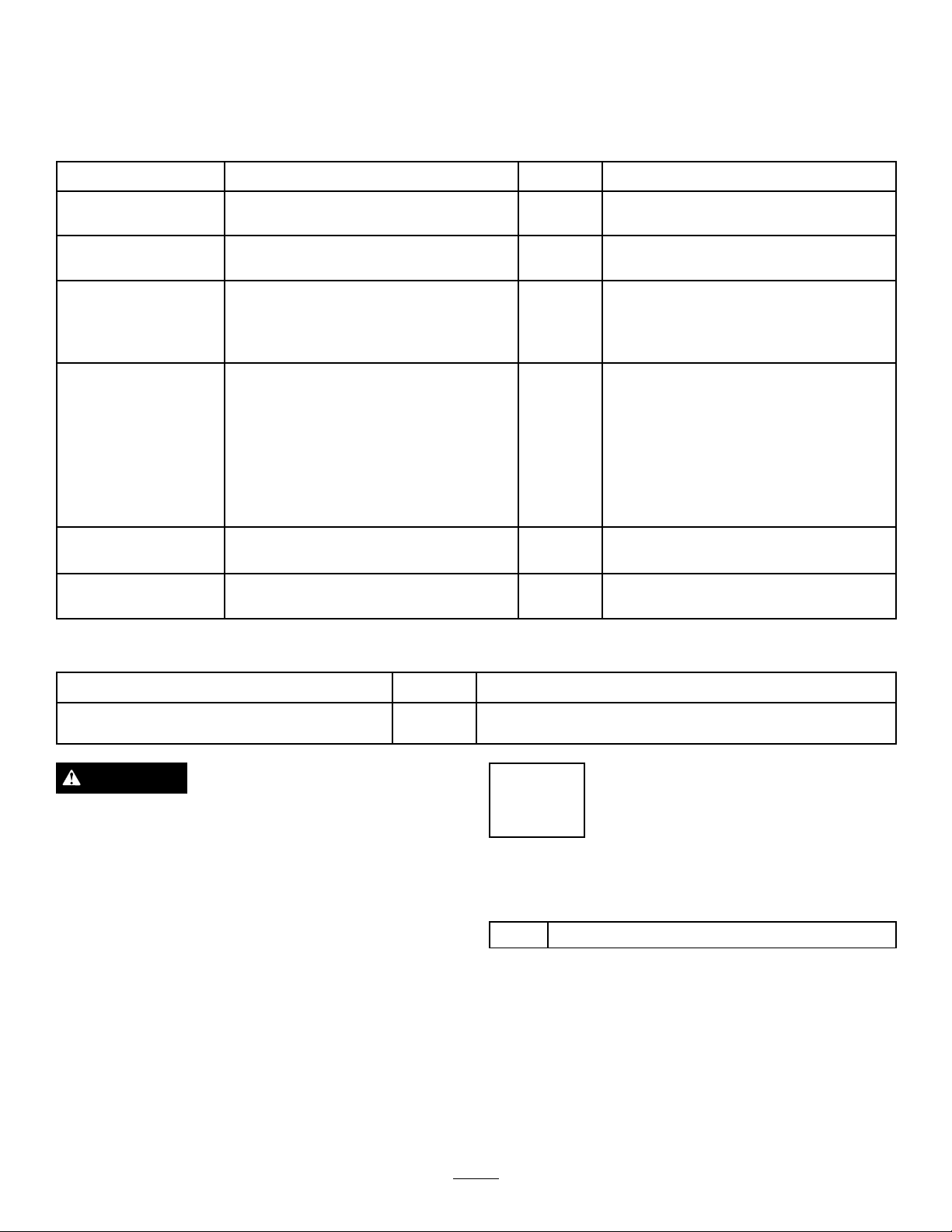
115-4505
1.Warning—readtheOperator'sManual.
2.Tippinghazard—lowerthecuttingunitwhendrivingdown
slopes.For2wheeldriveunits,adda16kg(35lb)rear
weighttoGM3280Dunitsanda32kg(70lb)rearweightto
GM3320units.For4wheeldrive3280Dunits,adda16
kg(35lb)rearweight.
7
Page 8
Setup
LooseParts
Usethechartbelowtoverifythatallpartshavebeenshipped.
ProcedureDescription
1
2
3
4
5
6
Completionkit(soldseparately)
Castorwheelassembly
Liftarm,right
Liftarm,left
Pivotpinassembly2
Cotterpin
Thrustwasher4
Clevispin
Hairpincotter2
Height-of-cutcollar
Clevispin
Hairpincotter2
Bolt(1/2x3/4inch)
Washer2
Nopartsrequired
Nopartsrequired
Qty.
1Installacompletionkit.
2Installthecastorwheelassemblies.
1
1
2
4
2
2
2
–
–
Installtheliftarms.
Installthecuttingunits
ConnectthePTOshafttothecutting
unitgearbox.
Greasethemachine.
Use
MediaandAdditionalParts
Description
PartsCatalog
Operator'sManual
DANGER
IftheengineisstartedandthePTOshaftisallowed
torotate,seriousinjurycouldresult.
DonotstarttheengineandengagethePTOlever
whenthePTOshaftisnotconnectedtothegear
boxonthecuttingunit.
Note:Determinetheleftandrightsidesofthemachine
fromthenormaloperatingposition.
Qty.
Use
1
1
1
InstallingaCompletionKit
Partsneededforthisprocedure:
1
Completionkit(soldseparately)
Procedure
Installoneofthefollowing62inchor72inchcompletionkits
tothebasedeckusingtheinstructionprovidedinthekit:
•Model30303,72inchRearDischarge
•Model30304,72inchGuardian
•Model30305,62inchRearDischarge
•Model30306,62inchGuardian
8
Page 9

2
3
InstallingtheCastorWheel
Assemblies
Partsneededforthisprocedure:
2
Castorwheelassembly
Procedure
Thethrustwashers,spacers,andtensioningcapshavebeen
installedonthecastorwheelspindlesforshipping.
1.Removethetensioningcapsfromthespindleshafts
andslideoffthespacersandthrustwashers(Figure2).
InstallingtheLiftArms
Partsneededforthisprocedure:
1
Liftarm,right
1
Liftarm,left
2Pivotpinassembly
2
Cotterpin
Procedure
1.Ononesideofthetractionunit,loosen(donot
remove)thewheelnutssecuringthewheelandtire
assemblytothefrontwheelstuds.
2.Jackupthemachineuntilthefrontwheelisoffofthe
oor.Usejackstandsorblockthemachinetoprevent
itfromaccidentallyfalling.
3.Removethewheelnutsandslidethewheelandtire
assemblyoffofthestuds.
4.Mountaliftarmtothepivotbracketwithapivotpin
andacotterpin(
bendpositionedoutward.
Figure3).Mounttheliftarmwiththe
Figure2
1.Tensioningcap4.Axlemountingholes
2.Spacers5.Castorwheel
3.Thrustwashers
2.Slidethespacersontothecastorspindletogetthe
desiredheight-of-cut;refertoFigure7&Figure8to
determinethecombinationsofspacersforthesetting.
Slideathrustwasherontothespindle,pushthecastor
throughthecastorarm.Installanotherthrustwasher
andtheremainingspacersontothespindleandinstall
thetensioningcaptosecuretheassembly(
Important:Thethrustwashers,notthespacers,
mustcontactthetopandbottomofthecastorarm.
Figure2).
Figure3
1.Pivotpin3.Pivotbracket
2.Liftarm
5.Hookthebrakereturnspringtothetabonthelift
arm(Figure3).
6.Installthewheelandtireassembly.Torquethewheel
nutsto102–108N-m(75–80ft-lb).
7.Repeattheprocedureontheoppositesideofthe
machine.
4.Brakereturnspring
9
Page 10

4
InstallingtheCuttingUnitson
theLiftArms
Partsneededforthisprocedure:
4Thrustwasher
4
Clevispin
2Hairpincotter
2
Height-of-cutcollar
2
Clevispin
2Hairpincotter
2
Bolt(1/2x3/4inch)
2Washer
Procedure
1.Movethecuttingunitintopositioninfrontofthe
tractionunit.
2.MovetheliftlevertotheFloatposition.Pushaliftarm
downuntiltheholesintheliftarmlineupwiththe
holesinthecastorarmbracketandtheheightofcut
rodcanbeinsertedintotheliftarmpads(Figure4).
Figure4
1.Liftarm
2.Castorarmbracket8.Height-of-cutcollar
3.Height-of-cutrod9.Clevispin
4.Liftarmpads
5.Thrustwashers11.Bolt
6.Clevispin
3.Securetheliftarmtothecastorarmwith2thrust
washers,aclevispinandahairpincotter.Positionthe
thrustwashersbetweentheliftarmandthecastorarm
bracket(Figure4).Insertendofcotterpinintotheslot
inthecastorarmtabtoretaincotterpin.
4.Repeattheprocedureontheoppositeliftarm.
5.Startthetractionunitandraisethecuttingunit.
6.Pushdownontherearofthecuttingunitandinsert
theheightofcutrodsthroughtheliftarmpads.
7.Installtheheightofcutcollarsontotheheightofcut
rodsandsecurewiththeclevispinsandhairpincotters
(Figure4).Positiontheheadoftheclevispintoward
thefrontofthedeck,ifpossible.
7.Hairpincotter
10.Hairpincotter
8.Installabolt(1/2x3/4inch)andawashertotopof
eachheightofcutrod(
10
Figure4).
Page 11

ProductOverview
5
ConnectingthePTOShaftto
theCuttingUnitGearBox
NoPartsRequired
Procedure
1.SlidethemalePTOshaftintothefemalePTOshaft
(Figure5).Alignthemountingholesinthegearcase
inputshaftwiththeholesinthePTOshaftandslide
themtogether.
Specications
Note:Specicationsanddesignaresubjecttochange
withoutnotice.
Widthof
Cut
Height
ofCut
Net
Weight
Attachments/Accessories
AselectionofToroapprovedattachmentsandaccessoriesis
availableforusewiththemachinetoenhanceandexpand
itscapabilities.ContactyourAuthorizedServiceDealeror
Distributororgotowww .Toro.comforalistofallapproved
attachmentsandaccessories.
1.575m(62inches)or1.829m(72inches)
Adjustablefrom25to127mm(1to5inches)in13
mm(1/2inch)increments
Model30403–190kg(420lbs.)
Model30404–231kg(510lbs.)
Figure5
1.PTOshaft3.Gearcase
2.Boltsandlocknuts4.Rollpin
2.Securethemwitharollpin(Figure5).
3.Tightentheboltsandnuts(Figure5).
6
GreasingtheMachine
NoPartsRequired
Procedure
Beforeoperatingthemachine,itmustbegreasedtoensure
properlubricatingcharacteristics;refertoGreasingthe
BearingsandBushings.Failuretoproperlygreasethemachine
willresultinprematurefailureofcriticalparts.
11
Page 12

Operation
engineandremovethekeyafterthecuttingunitis
raised.
Note:Determinetheleftandrightsidesofthemachine
fromthenormaloperatingposition.
CAUTION
Ifyouleavethekeyintheignitionswitch,someone
couldaccidentlystarttheengineandseriously
injureyouorotherbystanders.
Removethekeyfromtheignitionbeforeyoudoany
maintenance.
CheckingtheLubricantinthe GearBox
ThegearboxindesignedtooperateonSAE80–90wt.gear
lube.Althoughthegearboxisshippedwithlubricantfrom
thefactory,checkthelevelbeforeoperatingthecuttingunit.
1.Positionthemachineandcuttingunitonalevelsurface.
2.Removethedipstick/llplugfromthetopofthegear
box(Figure6)andmakesurethatthelubricantis
betweenthemarksonthedipstick.Ifthelubricant
levelislow,addenoughlubricantuntilthelevelis
betweenthemarks.
2.Positionthecastorwheelaxlesinthesameholesin
bothcastorforks.Referto
determinethecorrectholesforthesetting.
Note:Whenoperatingin64mm(2–1/2inch)height
ofcutorhigher,theaxleboltmustbeinstalledinthe
lowercastorforkholetopreventgrassbuildupbetween
thewheelandthefork.Whenoperatinginheightof
cutslowerthan64mm(2–1/2inch)andgrassbuildup
isdetected,reversethemachinesdirectiontopullany
clippingsawayfromthewheel/forkarea.
3.Removethetensioningcapfromthespindleshaft
(Figure7)andslidethespindleoutofthecastorarm.
Putthe2shims(1/8inch)ontothespindleshaftas
theywereoriginallyinstalled.Theseshimsarerequired
toachievealevelacrosstheentirewidthofthecutting
units.Slidetheappropriatenumberof1/2inchspacers
ontothespindleshafttogetthedesiredheight-of-cut;
thenslidethewasherontotheshaft.
RefertoFigure7&Figure8todeterminethe
combinationsofspacersforthesetting.
Figure7&Figure8to
Figure6
1.Dipstick/llplug
AdjustingtheHeight-of-Cut
Theheight-of-cutisadjustablefrom25to127mm(1to
5inches)in13mm(1/2inch)increments.Toadjustthe
height-of-cut,positionthecastorwheelaxlesintheupper
orlowerholesofthecastorforks,addorremoveanequal
numberofspacersfromthecastorforksandsecuretheheight
ofcutcollartothedesiredholesintheheightofcutrod.
1.Starttheengineandraisethecuttingunitofftheoor
sothattheheight-of-cutcanbechanged.Stopthe
Figure7
1.Tensioningcap4.Axlemountingholes
2.Spacers5.CastorWheel
3.Shims
Figure8
12
Page 13

4.Pushthecastorspindlethroughthecastorarm.Install
theshims(astheywereoriginallyinstalled)andthe
remainingspacersontothespindleshaft.Installthe
tensioningcaptosecuretheassembly.
5.Removethehairpinandclevispinsecuringtheheight
ofcutcollartotheheightofcutrodontherearofthe
cuttingunit(Figure9).
Figure9
1.Height-of-cutrod3.Clevispinandhairpin
cotter
2.Height-of-cutcollar
AdjustingtheCuttingUnit Pitch
Cuttingunitpitchisthedifferenceinheight-of-cutfromthe
frontofthebladeplanetothebackofthebladeplane.T oro
recommendsabladepitchof6mm(1/4inch).Thatisthe
backofthebladeplaneis6mm(1/4inch)higherthanthe
front.
1.Positionthemachineonalevelsurfaceontheshop
oor.
2.Setthecuttingunittothedesiredheight-of-cut.
3.Rotate1bladesothatitpointsstraightforward.
4.Usingashortruler,measurefromtheoortothefront
tipoftheblade.Rotatethebladetiptotherearand
measurefromtheoortothetipoftheblade.
5.Subtractthefrontdimensionfromthereardimension
tocalculatethebladepitch.
6.Loosenthejamnutsonthebottomoftheheight-of-cut
Figure11).
rods(
6.Aligntheheight-of-cutcollartothedesired
height-of-cutholesontheheightofcutrod(
Figure10
7.Securetheadjustmentwiththeclevispinandhairpin.
Figure10).
Figure11
1.Height-of-cut
7.Rotatetheheight-of-cutrodstoraiseorlowertherear
ofthecuttingunitandattainthecorrectcuttingunit
pitch.
8.Tightenthejamnuts.
2.Jamnut
AdjustingtheSkids
Theskidsshouldbemountedinthelowerpositionwhen
operatinginheightofcutsgreaterthan64mm(2-1/2inches)
andinthehigherpositionwhenoperatinginheightofcuts
lowerthan64mm(2-1/2inches).
Note:Positiontheheadoftheclevispintowardthe
frontofthedeck,ifpossible.
Note:Whenusing25mm(1inch),38mm(1-1/2
inch),oroccasionally51mm(2inch)height–of–cut,
movetheskidsandrollertothehighestholes.
Adjusttheskidsbyremovingtheangeboltandnuts,
positioningthemasdesired,andinstallingthefasteners
(
Figure12).
13
Page 14

4.Checkforbentblades;refertoCheckingforaBent
Blade.
5.Cutgrassinatestareatodetermineifallcuttingunits
arecuttingatthesameheight.
6.Ifcuttingunitadjustmentsarestillneeded,ndaat
surfaceusinga2m(6foot)orlongerstraightedge.
7.Toeasemeasuringbladeplane,raisetheheightofcut
tothehighestposition;refertoAdjustingtheHeight
ofCut.
Figure12
1.Skid
AdjustingtheRollers
Note:Ifthecuttingunitistobeusedinthe25or38mm(1
or1-1/2inch)height-of-cutsetting,thecuttingunitrollers
mustberepositionedinthetopbracketholes.
1.Removethescrewandnutsecuringtherollershaftto
thedeckbracket(Figure13).
8.Lowercuttingunitontotheatsurface.Removethe
coversfromthetopofthecuttingunits.
9.Rotatethebladeoneachspindleuntiltheendsface
forwardandbackward.
10.Measurefromtheoortothefronttipofthecutting
edge.
11.Adjust1/8inchshimsoncastorfork(s)tomatch
heightofcuttodecal(
CuttingUnitPitch.
Figure14);refertoAdjustingthe
Figure13
1.Roller
2.Slidetheshaftoutofthelowerbracketholes,alignthe
rollerwiththetopholes,andinstalltheshaft.
3.Installthescrewandnuttosecuretheassemblies.
2.Rollershaft
CorrectingCuttingUnit Mismatch
Duetodifferencesingrassconditionsandthecounterbalance
settingofthetractionunit,itisadvisedthatgrassbecutand
appearancecheckedbeforeformalcuttingisstarted.
1.Setthecuttingunittothedesiredheightofcut;referto
AdjustingtheHeightofCut.
2.Checkandadjustfrontandreartractortirepressureto
172–207kPa(25–30psi).
3.Checkandadjustallcastortirepressuresto345kPa
(50psi).
Figure14
1.Tensioningcap4.Axlemountingholes
2.Spacers5.Castorwheel
3.Shims
OperatingTips
MowWhenGrassisDry
Moweitherinthelatemorningtoavoidthedew ,whichcauses
grassclumping,orinlateafternoontoavoidthedamage
thatcanbecausedbydirectsunlightonthesensitive,freshly
mowedgrass.
SelecttheProperHeight-of-CutSetting
toSuitConditions
Removeapproximately25mm(1inch)ornomorethan1/3
ofthegrassbladewhencutting.Inexceptionallylushand
14
Page 15

densegrass,youmayhavetoraisetheheight-of-cuttothe
nextsetting.
MowatProperIntervals
Undermostnormalconditionsyouwillneedtomow
approximatelyevery4–5days.Butremember,grassgrowsat
differentratesatdifferenttimes.Thismeansthatinorderto
maintainthesameheight-of-cut,whichisagoodpractice,
youwillneedtocutmorefrequentlyinearlyspring;asthe
grassgrowthrateslowsinmidsummer,cutonlyevery8–10
days.Ifyouareunabletomowforanextendedperioddue
toweatherconditionsorotherreasons,mowrstwiththe
height-of-cutatahighlevel;thenmowagain2–3dayslater
withalowerheightsetting.
AlwaysMowwithSharpBlades
Asharpbladecutscleanlyandwithouttearingorshredding
thegrassbladeslikeadullblade.Tearingandshredding
causesthegrasstoturnbrownattheedgeswhichimpairs
growthandincreasessusceptibilitytodiseases.
AfterOperating
Toensureoptimumperformance,cleantheundersideofthe
mowerhousingaftereachuse.Ifresidueisallowedtobuild
upinthemowerhousing,cuttingperformancewilldecrease.
CuttingUnitPitch
Werecommendabladepitchof6mm(1/4inch).Apitch
largerthan6mm(1/4inch)willresultinlesspowerrequired,
largerclippings,andapoorerqualityofcut.Apitchlessthan
6mm(1/4inch)willresultinmorepowerrequired,smaller
clippingsandabetterqualityofcut.
15
Page 16

Maintenance
RecommendedMaintenanceSchedule(s)
MaintenanceService
Interval
Aftertherst2hours
Aftertherst10hours
Beforeeachuseordaily
Every50hours
Every400hours
1
Immediatelyaftereverywashing,regardlessoftheintervallisted
MaintenanceProcedure
•Tightenthecastorwheelnuts
•Tightenthecastorwheelnuts
•T orquethebladebolts
•Checktheblades
•Lubricatethegreasettings1
•Checkthegearboxoillevel
•Tightenthecastorwheelnuts
•T orquethebladebolts
•Checkthebladedrivebeltadjustment
•Cleanunderthecuttingunitbeltcovers
•Changethegearboxoil
CAUTION
Ifyouleavethekeyintheignitionswitch,someonecouldaccidentallystarttheengineandseriously
injureyouorotherbystanders.
Removethekeyfromtheignitionswitchbeforeyoudoanymaintenance.
Important:Thefastenersonthecoversofthismachinearedesignedtoremainonthecoverafterremoval.Loosen
allofthefastenersoneachcoverafewturnssothatthecoverisloosebutstillattached,thengobackandloosen
themuntilthecovercomesfree.Thiswillpreventyoufromaccidentallystrippingtheboltsfreeoftheretainers.
Lubrication
Themachinehasgreasettingsthatmustbelubricated
regularlywithNo.2GeneralPurposeLithiumBaseGrease.
Ifthemachineisoperatedundernormalconditions,lubricate
allbearingsandbushingsafterevery50hoursofoperationor
immediatelyaftereverywashing.
1.Lubricatethefollowingareas:
•Castorforkshaftbushings(2)(
Figure15)
Figure15
•Spindleshaftbearings(3)(locatedunderthepulley)
(Figure16)
16
Page 17

Figure16
•Idlerarmshaftbearings(Figure16)
•Liftarmpivots,front(2)(Figure17)
Figure17
•Liftarmpivots,rear(2)(Figure18)
Figure19
1.Dipstick/llplug
SeparatingtheCuttingUnit fromtheTractionUnit
1.Positionthemachineonlevelsurface,lowerthecutting
unittotheoor,movetheliftlevertotheFloat
position,shuttheengineoff,andengagetheparking
brake.
2.Removetheboltandwashermountedtothetopof
eachheightofcutrod(Figure20).
Figure18
2.Positionthemachineandcuttingunitonalevelsurface
andlowerthecuttingunit.Removethedipstick/ll
plugfromthetopofthegearbox(Figure19)andmake
surethatthelubricantisbetweenthemarksonthe
dipstick.Ifthelubricantlevelislow,addSAE80-90
wt.gearlubeuntilthelevelisbetweenthemarks.
Figure20
1.Height-of-cutrod3.Height-of-cutcollar
2.Boltandwasher4.Hairpincotterandclevis
pin
3.Removethehairpinandclevispinsecuringtheheight
ofcutcollartotheheightofcutrodontherearof
thecuttingunit(Figure20).Removetheheightofcut
collar.
4.Removethehairpincottersandclevispinssecuring
theliftarmstothecastorarmbrackets(
17
Figure21).
Page 18

Figure21
holesinthecastorarmbracketandtheheightofcut
rodcanbeinsertedintotheliftarmpads(
Figure23).
1.Liftarm
2.Clevispin4.Castorarmbracket
3.Hairpincotter
5.Rollthecuttingunitawayfromthetractionunit,
separatingthemaleandfemalesectionsofthePTO
shaft(Figure22).
Figure22
1.PTOshaft
DANGER
IftheengineisstartedandthePTOshaftis
allowedtorotate,seriousinjurycouldresult.
Figure23
1.Liftarm
2.Castorarmbracket8.Height-of-cutcollar
3.Height-of-cutrod9.Clevispin
4.Liftarmpads
5.Thrustwashers11.Bolt
6.Clevispin
7.Hairpincotter
10.Hairpincotter
DonotstarttheengineandengagethePTO
leverwhenthePTOshaftisnotconnectedto
thegearboxonthecuttingunit.
MountingtheCuttingUnitto theTractionUnit
1.Positionthemachineonalevelsurfaceandshutthe
engineoff.
2.Movethecuttingunitintopositioninfrontofthe
tractionunit.
3.SlidethemalePTOshaftintothefemalePTOshaft
Figure22).
(
4.MovetheliftlevertotheFloatposition.Pushaliftarm
downuntiltheholesintheliftarmlineupwiththe
5.Securetheliftarmtothecastorarmwith(2)thrust
washers,aclevispinandahairpincotter.Positionthe
thrustwashersbetweentheliftarmandthecastorarm
bracket(Figure23).Insertendofcotterpinintothe
slotinthecastorarmtabtoretaincotterpin.
6.Repeattheprocedureontheoppositeliftarm.
7.Startthetractionunitandraisethecuttingunit.
8.Pushdownontherearofthecuttingunitandinsert
theheightofcutrodsthroughtheliftarmpads.
9.Installtheheightofcutcollarsontotheheightofcut
rodsandsecurewiththeclevispinsandhairpincotters
(Figure23).Headofclevispintobepositionedtoward
thefrontofthedeck.
10.Installa1/2x3/4inchboltandawashertotopof
eachheightofcutrod(Figure23).
18
Page 19

ServicingtheBushingsinthe
G010549
CastorArms
Thecastorarmshavebushingspressedintothetopand
bottomofthetubeandaftermanyhoursofoperation,the
bushingswillwear.Tocheckthebushings,movethecastor
forkbackandforthandfromsidetoside.Ifthecastor
spindleislooseinsidethebushings,thebushingsareworn
andmustbereplaced.
1.Raisethecuttingunitsothatthewheelsareoffof
theoor.Blockthecuttingunitsothatitcannot
accidentallyfall.
2.Removethetensioningcap,spacer(s),andthrust
washerfromthetopofthecastorspindle.
3.Pullthecastorspindleoutofthemountingtube.
Allowthethrustwasherandspacer(s)toremainon
thebottomofthespindle.
Figure25
1.Castorwheel3.Bearing(2)
2.Castorfork
4.Bearingspacer
4.Insertapinpunchintothetoporbottomofthe
mountingtubeanddrivethebushingoutofthetube
Figure24).Alsodrivetheotherbushingoutofthe
(
tube.Cleantheinsideofthetubestoremovedirt.
Figure24
1.Castorarmtube
5.Applygreasetotheinsideandoutsideofthenew
bushings.Usingahammerandatplate,drivethe
bushingsintothemountingtube.
6.Inspectthecastorspindleforwearandreplaceitif
damaged.
7.Pushthecastorspindlethroughthebushingsand
mountingtube.Slidethethrustwasherandspacer(s)
ontothespindle.Installthetensioningcaponthe
castorspindletoretainallpartsinplace.
2.Bushings
2.Removethebearingfromthewheelhubandallow
thebearingspacertofallout(Figure25).Removethe
bearingfromtheoppositesideofthewheelhub.
3.Checkthebearings,spacer,andinsideofthewheelhub
forwear.Replaceanydamagedparts.
4.Toassemblethecastorwheel,pushthebearingintothe
wheelhub.Wheninstallingthebearings,pressonthe
outerraceofthebearing.
5.Slidethebearingspacerintothewheelhub.Pushthe
otherbearingintotheopenendofthewheelhubto
captivatethebearingspacerinsidethewheelhub.
6.Installthecastorwheelassemblybetweenthecastor
forkandsecureitinplacewiththeboltandlocknut.
CheckingforaBentBlade
1.Positionthemachineonalevelsurface.Raisethe
cuttingunit,engagetheparkingbrake,putthetraction
pedalinneutral,putthePTOleverintheOffposition,
stoptheengine,andremovetheignitionkey.Blockthe
cuttingunittopreventitfromaccidentallyfalling.
2.Rotatethebladeuntiltheendsfaceforwardand
backward.Measurefromtheinsideofthecuttingunit
tothecuttingedgeatthefrontoftheblade(Figure26),
andrememberthisdimension.
ServicingtheCastorWheels andBearings
1.Removethelocknutfromtheboltholdingthecastor
wheelassemblybetweenthecastorfork(Figure25).
Graspthecastorwheelandslidetheboltoutofthe
forkorpivotarm.
Figure26
3.Rotatetheoppositeendofthebladeforward.Measure
betweenthecuttingunitandcuttingedgeofthe
bladeatthesamepositionasinstep2Thedifference
betweenthedimensionsobtainedinsteps2and3must
notexceed3mm(1/8inch).Ifthedimensionexceeds
19
Page 20

3mm(1/8inch),replacethebladebecauseitisbent;
G010555
1
2
refertoRemovingtheCuttingBlade.
InspectingandSharpeningthe Blade(s)
RemovingandInstallingthe Blade(s)
Theblademustbereplacedifasolidobjectishit,the
bladeisout-of-balance,worn,orbent.Alwaysusegenuine
Tororeplacementbladestoensuresafetyandoptimum
performance.Neverusebladesmadebyothermanufacturers
becausetheycouldbedangerous.
1.Raisethecuttingunittothehighestposition,engage
theparkingbrake,stoptheengine,andremovethe
ignitionkey.Blockthecuttingunittopreventitfrom
accidentallyfalling.
2.Grasptheendofthebladeusingaragorthickly
paddedglove.Removethebladebolt,anti-scalpcup,
andbladefromthespindleshaft(Figure27).
Figure27
1.Bladebolt2.Anti-scalpcup
3.Installtheblade-sailfacingtowardthecuttingunit-with
theanti-scalpcupandbladebolt.Tightentheblade
boltto115-149N-m(85-110ft-lb).
Important:Thecurvedpartoftheblademustbe
pointingtowardtheinsideofthecuttingunitto
ensurepropercutting.
DANGER
Awornordamagedbladecanbreak,andapiece
ofthebladecouldbethrownintotheoperator's
orbystander'sarea,resultinginseriouspersonal
injuryordeath.
•Inspectthebladeperiodicallyforwearor
damage.
•Donottrytostraightenabladethatisbent.
•Neverweldabrokenorcrackedblade.
•Replaceawornordamagedbladewitha
newTorobladetoensurecontinuedsafety
certicationoftheproduct.
Twoareasmustbeconsideredwhencheckingandservicing
thecuttingblade:thesailandthecuttingedge.Bothcutting
edgesandthesail,whichistheturnedupportionopposite
thecuttingedge,contributetoagoodquality-of-cut.The
sailisimportantbecauseitpullsgrassupstraight,thereby
producinganevencut.However,thesailwillgraduallywear
downduringoperation,andthisconditionisnormal.Asthe
sailwearsdown,thequality-of-cutwilldegradesomewhat,
althoughthecuttingedgesaresharp.Thecuttingedgeof
theblademustbesharpsothatthegrassiscutratherthan
torn.Adullcuttingedgeisevidentwhenthetipsofthegrass
appearbrownandshredded.Sharpenthecuttingedgesto
correctthiscondition.
1.Positionthemachineonalevelsurface.Raisethe
cuttingunit,engagetheparkingbrake,putthetraction
pedalinneutral,putthePTOleverintheOffposition,
stoptheengine,andremovetheignitionkey.
2.Examinethecuttingendsofthebladecarefully,
especiallywheretheatandcurvedpartsoftheblade
meet(Figure28).Sincesandandabrasivematerialcan
wearawaythemetalthatconnectstheatandcurved
partsoftheblade,checkthebladebeforeusingthe
machine.Ifwearisnoticed(Figure28),replacethe
blade;refertoRemovingtheCuttingBlade.
Figure28
1.Cuttingedge3.Wear/slotforming
2.Curvedarea/sail4.Crack
20
Page 21

WARNING
Ifthebladeisallowedtowear,aslotwillform
betweenthesailandatpartoftheblade
Figure28).Eventually,apieceoftheblade
(
maybreakoffandbethrownfromunderthe
housing,possiblyresultinginseriousinjuryto
yourselforbystanders.
•Inspectthebladeperiodicallyforwearor
damage.
•Replaceawornordamagedbladewitha
newT orobladetoensurecontinuedsafety
certicationoftheproduct.
3.Examinethecuttingedgesofallblades.Sharpenthe
cuttingedgesiftheyaredullornicked.Sharpenonly
thetopsideofthecuttingedgeandmaintainthe
originalcuttingangletoensuresharpness(Figure29).
Thebladewillremainbalancedifthesameamountof
metalisremovedfrombothcuttingedges.
forward,andmeasureagain.Thedifferencebetween
thedimensionsmustnotexceed1meter(3foot).If
thedimensionexceeds1meter(3foot),replacethe
bladebecauseitisbent.Makesuretomeasureallof
theblades.
5.Comparethemeasurementsoftheouterbladeswith
thecenterblade.Thecenterblademustnotbemore
than1meter(3foot)lowerthantheouterblades.If
thecenterbladeismorethan1meter(3foot)lower
thantheouterblades,proceedtostep
betweenthespindlehousingandthebottomofthe
cuttingunit.
6.Removethebolts,atwashers,lockwashers,andnuts
fromtheouterspindleintheareawheretheshims
mustbeadded.Toraiseorlowertheblade,addashim,
PartNo.3256-24,betweenthespindlehousingand
thebottomofthecuttingunit.Continuetocheckthe
alignmentofthebladesandaddshimsuntilthetipsof
thebladesarewithintherequireddimension.
Important:Donotusemorethanthreeshimsat
anyoneholelocation.Usedecreasingnumbersof
shimsinadjacentholesifmorethanoneshimis
addedtoanyoneholelocation.
6andaddshims
Figure29
1.Sharpenatoriginalangle
Note:Removethebladesandsharpenthemona
grinder;refertoRemovingtheCuttingBlades.After
sharpeningthecuttingedges,installthebladewiththe
anti-scalpcupandbladebolt.Thebladesailsmustbe
ontopoftheblade.Tightenthebladeboltto115-149
N-m(85-110ft-lb).
CheckingandCorrecting MismatchofBlades
Ifthereismismatchbetweentheblades,thegrasswillappear
streakedwhenitiscut.Thisproblemcanbecorrectedby
makingsurethatthebladesarestraightandalloftheblades
arecuttingonthesameplane.
1.Usinga1meter(3foot)longcarpenterslevel,nda
levelsurfaceontheshopoor.
2.Raisetheheight-of-cuttothehighestposition;referto
AdjustingtheHeight-of-Cut.
3.Lowerthecuttingunitontotheatsurface.Remove
thecoversfromthetopofthecuttingunit.
4.Rotatethebladesuntiltheendsfaceforwardand
backward.Measurefromtheoortothefronttipof
thecuttingedge.Rememberthisdimension.Then
rotatethesamebladesothattheoppositeendis
7.Installthebeltcovers.
ReplacingtheDriveBelt
Thebladedrivebelt,tensionedbythespringloadedidler
pulley,isverydurable.However,aftermanyhoursofuse,
thebeltwillshowsignsofwear.Signsofawornbeltare:
squealingwhenbeltisrotating,bladesslippingwhencutting
grass,frayededges,burnmarksandcracks.Replacethebeltif
anyoftheseconditionsareevident.
1.Lowerthecuttingunittotheshopoor.Removethe
beltcoversfromthetopofthecuttingunitandsetthe
coversaside.
2.Usingatorquewrenchorsimilartool,movetheidler
pulley(Figure30)awayfromthedrivebelttorelease
thebelttensionandallowthebelttobeslippedoffthe
gearboxpulley(Figure31).
Figure30
1.Idlerpulley
21
Page 22

Figure31
1.Gearbox
3.Removetheoldbeltfromaroundthespindlepulleys
andidlerpulley.
4.Routethenewbeltaroundthespindlepulleysandidler
pulleyassemblyasshowninFigure32.
Figure32
1.Beltrouting
5.Installthebeltcovers.
22
Page 23

DeclarationofIncorporation
TheT oroCompany,811 1LyndaleAve.South,Bloomington,MN,USAdeclaresthatthefollowingunit(s)
conform(s)tothedirectiveslisted,wheninstalledinaccordancewiththeaccompanyinginstructionsontocertain
ToromodelsasindicatedontherelevantDeclarationsofConformity.
ModelNo.
30403314000001andUpBase62inMower
30404314000001andUpBase72inMower
SerialNo.
ProductDescriptionInvoiceDescription
GeneralDescription
62”BASEDECK-GM3280
72”BASEDECK-GM3280
Base62inMower
Base72inMower
Directive
2006/42/EC,
2000/14/EC
2006/42/EC,
2000/14/EC
RelevanttechnicaldocumentationhasbeencompiledasrequiredperPartBofAnnexVIIof2006/42/EC.
Wewillundertaketotransmit,inresponsetorequestsbynationalauthorities,relevantinformationonthispartly
completedmachinery.Themethodoftransmissionshallbeelectronictransmittal.
ThismachineryshallnotbeputintoserviceuntilincorporatedintoapprovedToromodelsasindicatedonthe
associatedDeclarationofConformityandinaccordancewithallinstructions,wherebyitcanbedeclaredin
conformitywithallrelevantDirectives.
Certied:EUTechnicalContact:
PeterT etteroo
ToroEuropeNV
B-2260Oevel-Westerloo
Belgium
DavidKlisTel.003214562960
Sr.EngineeringManager
811 1LyndaleAve.South
Bloomington,MN55420,USA
September26,2013
Fax003214581911
23
Page 24

TheToroT otalCoverageGuarantee
ALimitedWarranty
ConditionsandProductsCovered
TheToroCompanyanditsafliate,T oroWarrantyCompany,pursuant
toanagreementbetweenthem,jointlywarrantyourToroCommercial
product(“Product”)tobefreefromdefectsinmaterialsorworkmanship
fortwoyearsor1500operationalhours*,whicheveroccursrst.This
warrantyisapplicabletoallproductswiththeexceptionofAerators
(refertoseparatewarrantystatementsfortheseproducts).Wherea
warrantableconditionexists,wewillrepairtheProductatnocosttoyou
includingdiagnostics,labor,parts,andtransportation.Thiswarranty
beginsonthedatetheProductisdeliveredtotheoriginalretailpurchaser.
*Productequippedwithanhourmeter.
InstructionsforObtainingWarrantyService
YouareresponsiblefornotifyingtheCommercialProductsDistributoror
AuthorizedCommercialProductsDealerfromwhomyoupurchasedthe
Productassoonasyoubelieveawarrantableconditionexists.Ifyouneed
helplocatingaCommercialProductsDistributororAuthorizedDealer,or
ifyouhavequestionsregardingyourwarrantyrightsorresponsibilities,
youmaycontactusat:
ToroCommercialProductsServiceDepartment
ToroWarrantyCompany
811 1LyndaleAvenueSouth
Bloomington,MN55420-1196
952–888–8801or800–952–2740
E-mail:commercial.warranty@toro.com
OwnerResponsibilities
AstheProductowner,youareresponsibleforrequiredmaintenance
andadjustmentsstatedinyourOperator'sManual.Failuretoperform
requiredmaintenanceandadjustmentscanbegroundsfordisallowinga
warrantyclaim.
ItemsandConditionsNotCovered
Notallproductfailuresormalfunctionsthatoccurduringthewarranty
periodaredefectsinmaterialsorworkmanship.Thiswarrantydoesnot
coverthefollowing:
•Productfailureswhichresultfromtheuseofnon-Tororeplacement
parts,orfrominstallationanduseofadd-on,ormodiednon-T oro
brandedaccessoriesandproducts.Aseparatewarrantymaybe
providedbythemanufactureroftheseitems.
•Productfailureswhichresultfromfailuretoperformrecommended
maintenanceand/oradjustments.Failuretoproperlymaintainyour
ToroproductpertheRecommendedMaintenancelistedinthe
Operator’sManualcanresultinclaimsforwarrantybeingdenied.
•ProductfailureswhichresultfromoperatingtheProductinan
abusive,negligent,orrecklessmanner.
•Partssubjecttoconsumptionthroughuseunlessfoundtobe
defective.Examplesofpartswhichareconsumed,orusedup,
duringnormalProductoperationinclude,butarenotlimitedto,brake
padsandlinings,clutchlinings,blades,reels,rollersandbearings
(sealedorgreasable),bedknives,sparkplugs,castorwheelsand
bearings,tires,lters,belts,andcertainsprayercomponentssuchas
diaphragms,nozzles,andcheckvalves,etc.
•Failurescausedbyoutsideinuence.Conditionsconsideredtobe
outsideinuenceinclude,butarenotlimitedto,weather,storage
practices,contamination,useofunapprovedfuels,coolants,
lubricants,additives,fertilizers,water,orchemicals,etc.
•Failureorperformanceissuesduetotheuseoffuels(e.g.gasoline,
diesel,orbiodiesel)thatdonotconformtotheirrespectiveindustry
standards.
•Normalnoise,vibration,wearandtear,anddeterioration.
•Normal“wearandtear”includes,butisnotlimitedto,damageto
seatsduetowearorabrasion,wornpaintedsurfaces,scratched
decalsorwindows,etc.
Parts
Partsscheduledforreplacementasrequiredmaintenancearewarranted
fortheperiodoftimeuptothescheduledreplacementtimeforthatpart.
Partsreplacedunderthiswarrantyarecoveredforthedurationofthe
originalproductwarrantyandbecomethepropertyofT oro.T orowill
makethenaldecisionwhethertorepairanyexistingpartorassemblyor
replaceit.T oromayuseremanufacturedpartsforwarrantyrepairs.
DeepCycleandLithium-IonBatteryWarranty:
DeepcycleandLithium-Ionbatterieshaveaspeciedtotalnumberof
kilowatt-hourstheycandeliverduringtheirlifetime.Operating,recharging,
andmaintenancetechniquescanextendorreducetotalbatterylife.Asthe
batteriesinthisproductareconsumed,theamountofusefulworkbetween
chargingintervalswillslowlydecreaseuntilthebatteryiscompletelyworn
out.Replacementofwornoutbatteries,duetonormalconsumption,
istheresponsibilityoftheproductowner.Batteryreplacementmaybe
requiredduringthenormalproductwarrantyperiodatowner’sexpense.
Note:(Lithium-Ionbatteryonly):ALithium-Ionbatteryhasapartonly
proratedwarrantybeginningyear3throughyear5basedonthetime
inserviceandkilowatthoursused.RefertotheOperator'sManualfor
additionalinformation.
MaintenanceisatOwner’sExpense
Enginetune-up,lubrication,cleaningandpolishing,replacementoflters,
coolant,andcompletingrecommendedmaintenancearesomeofthe
normalservicesT oroproductsrequirethatareattheowner’sexpense.
GeneralConditions
RepairbyanAuthorizedT oroDistributororDealerisyoursoleremedy
underthiswarranty.
NeitherTheToroCompanynorT oroWarrantyCompanyisliablefor
indirect,incidentalorconsequentialdamagesinconnectionwiththe
useoftheToroProductscoveredbythiswarranty ,includingany
costorexpenseofprovidingsubstituteequipmentorserviceduring
reasonableperiodsofmalfunctionornon-usependingcompletion
ofrepairsunderthiswarranty.ExceptfortheEmissionswarranty
referencedbelow,ifapplicable,thereisnootherexpresswarranty .
Allimpliedwarrantiesofmerchantabilityandtnessforuseare
limitedtothedurationofthisexpresswarranty .
Somestatesdonotallowexclusionsofincidentalorconsequential
damages,orlimitationsonhowlonganimpliedwarrantylasts,sothe
aboveexclusionsandlimitationsmaynotapplytoyou.Thiswarranty
givesyouspeciclegalrights,andyoumayalsohaveotherrightswhich
varyfromstatetostate.
Noteregardingenginewarranty:
TheEmissionsControlSystemonyourProductmaybecoveredby
aseparatewarrantymeetingrequirementsestablishedbytheU.S.
EnvironmentalProtectionAgency(EPA)and/ortheCaliforniaAir
ResourcesBoard(CARB).Thehourlimitationssetforthabovedonot
applytotheEmissionsControlSystemWarranty.RefertotheEngine
EmissionControlWarrantyStatementsuppliedwithyourproductor
containedintheenginemanufacturer’sdocumentationfordetails
CountriesOtherthantheUnitedStatesorCanada
CustomerswhohavepurchasedT oroproductsexportedfromtheUnitedStatesorCanadashouldcontacttheirT oroDistributor(Dealer)toobtain
guaranteepoliciesforyourcountry ,province,orstate.IfforanyreasonyouaredissatisedwithyourDistributor'sserviceorhavedifcultyobtaining
guaranteeinformation,contacttheT oroimporter.
374-0253RevB
 Loading...