

Page 1
FORM NO. 3319-384GB Rev A
®
MODEL NO. 30385—70001 & OVER
OPERATOR'S
84” REAR DISCHANGE DECK
MANUAL
©The T oro Company—1997
Page 2

Table of Contents
SPECIFICATIONS 2
SAFETY INSTRUCTIONS 3
Symbol Glossary 6
BEFORE OPERATING 9
Check Lubricant in Gear Box 9
Adjusting Height-of-Cut 9
Adjusting Skids 9
Adjusting Rollers 10
Adjusting Deck Pitch 10
OPERATING INSTRUCTIONS 11
Operating Tips 11
Specifications
T ype: 84" (213 cm) width of cut, 5 blades, 3-blade center section, and 2 one-blade wings. Toro Recycler technology.
Mowing Rate: Mows up to 4.4 acres/hr at 8.8 kmh.
T rimming Ability: Deck is centered on tractor with
12.7 cm of over hang on each side. Uncut circle is 61
cm on both left and right with no brakes.
Height Of Cut: 2.5–12.7 cm adjustable in 1.7 cm increments. Front adjustment is with snapper pin and grooves
in castor shaft. Rear adjustment is with hanger brackets
and pin.
MAINTENANCE 12
Lubrication 12
Disconnecting Cutting Unit from Traction Unit 13
Connecting Cutting Unit to Traction Unit 13
Changing Gear Box Lubricant 14
Replacing Drive Belt 15
Servicing Front Bushings in Castor Forks 16
Servicing Castor Wheels and Bearings 18
Removing Cutter Blades 17
Inspecting and Sharpening Blades 17
Correcting Cutting Unit Mismatch 18
IDENTIFICA TION AND ORDERING 18
3.2 cm diameter spindle shafts, turn on two greaseable
tapered roller bearings (greaseable from top of deck). A
positive splined connection attaches pulleys to spindle
shafts for high-torque capacity.
Blades: Five 48-cm long, 6.3-mm thick, heat-treated
steel.
Suspension & Castor Wheels: Two front castors, consisting of 25.4 cm pneumatic wheel and tire assembly
with sealed ball bearings. Rear of deck is suspended from
lift arms with adjustable deck rake. Hydraulic counter
balance and lift system designed integral with deck for
maximum flotation.
Construction: 12-gauge steel, 10.8 cm deep, welded
construction and reinforced with 10-gauge steel channels. Bolt-in 12-gauge steel recycling chambers.
Cutter Drive: Isolation mount PTO driven gearbox
with 1:1.35 spiral bevel gears. One "BB" section belt on
center section. One "B" section belt on each wing. Fixed
idler on main deck with spring adjustment. Self-tensioning idler pulleys on each wing.
2
Deck Covers: High-impact plastic covers.
Quick Attach System: Tapered joint with over center
adjustable tensioning latch.
Weight: 243 kg.
Specifications and design subject to change without
notice.
Page 3

SAFETY
Training
1. Read the instructions carefully. Be familiar with
the controls and the proper use of the equipment.
2. Never allow children or people unfamiliar with
these instructions to use the lawnmower. Local regulations may restrict the age of the operator.
3. Never mow while people, especially children, or
pets are nearby.
4. Keep in mind that the operator or user is responsi-
ble for accidents or hazards occurring to other people or their property.
5. Do not carry passengers.
6. All drivers should seek and obtain professional and
practical instruction. Such instruction should
emphasize:
• the need for care and concentration when working with rideon machines;
• Refuel outdoors only and do not smoke while
refueling.
• Add fuel before starting the engine. Never
remove the cap of the fuel tank or add petrol
while the engine is running or when the engine
is hot.
• If petrol is spilled, do not attempt to start the
engine but move the machine away from the
area of spillage and avoid creating any source of
ignition until petrol vapors have dissipated.
• Replace all fuel tanks and container caps
securely.
4. Replace faulty silencers.
5. Before using, always visually inspect to see that the
blades, blade bolts and cutter assembly are not
worn or damaged. Replace worn or damaged
blades and bolts in sets to preserve balance.
6. On multi-bladed machines, take care as rotating
one blade can cause other blades to rotate.
• control of a ride on machine sliding on a slope
will not be regained by the application of the
brake. The main reasons for loss of control are:
– insufficient wheel grip;
– being driven too fast;
– inadequate braking;
– the type of machine is unsuitable for its task;
– lack of awareness of the effects of ground
conditions, especially slopes;
Preparation
1. While mowing, always wear substantial footwear
and long trousers. Do not operate the equipment
when barefoot or wearing open sandals.
2. Thoroughly inspect the area where the equipment is
to be used and remove all objects which may be
thrown by the machine.
3. WARNING—Petrol is highly flammable.
• Store fuel in containers specifically designed for
this purpose.
Operation
1. Do not operate the engine in a confined space
where dangerous carbon monoxide fumes can collect.
2. Mow only in daylight or in good artificial light.
3. Before attempting to start the engine, disengage all
blade attachment clutches and shift into neutral.
4. Do not use on slopes of more than:
• Never mow side hills over 5°
• Never mow uphill over 10°
• Never mow downhill over 15°
5. Remember there is no such thing as a “safe” slope.
Travel on grass9 slopes requires particular care. To
guard against overturning:
• do not stop or start suddenly when going up or
downhill;
• engage clutch slowly, always keep machine in
gear, especially when travailing downhill;
• machine speeds should be kept low on slopes
3
Page 4

and during tight turns;
• stay alert for bumps and hollows and other hidden
hazards;
• never mow across the face of the slope, unless the
lawnmower is designed for this purpose.
6. Use care when pulling loads or using heavy equip-
ment.
• if the machine starts to vibrate abnormally
(check immediately).
14. Disengage drive to attachments when transporting
or not in use.
15. Stop the engine and disengage drive to attachment
• before refueling;
• Use only approved drawbar hitch points.
• Limit loads to those you can safely control.
• Do not turn sharply. Use care when reversing.
• Use counterweight(s) or wheel weights when suggested in the instruction handbook .
7. Watch out for traffic when crossing or near road-
ways.
8. Stop the blades rotating before crossing surfaces
other than grass.
9. When using any attachments, never direct discharge
of material toward bystanders nor allow anyone near
the machine while in operation .
10. Never operate the lawnmower with defective guards,
shields or without safety protective devices in place.
11. Do not change the engine governor settings or over-
speed the engine. Operating the engine at excessive
speeds may increase the hazard of personal injury.
• before removing the grass catcher;
• before making height adjustment unless adjustment can be made from the operator's position.
16. Reduce the throttle setting during engine runout
and, if the engine is provided with a shutoff valve,
turn the fuel off at the conclusion of mowing.
Maintenance and Storage
1. Keep all nuts, bolts and screws tight to be sure the
equipment is in safe working condition.
2. Never store the equipment with petrol in the tank
inside a building where fumes may reach an open
flame or spark.
3. Allow the engine to cool before storing in any
enclosure.
4. To reduce the fire hazard, keep the engine, silencer,
battery compartment and petrol storage area free of
grass, leaves, or excessive grease.
12. Before leaving the operator's position:
• disengage the power take-off and lower the
attachments;
• change into neutral and set the parking brake;
• stop the engine and remove the key.
13. Disengage drive to attachments, stop the engine, and
disconnect the spark plug wire(s)or remove the ignition key
• before cleaning blockages or unclogging chute;
• before checking, cleaning or working on the
lawnmower;
• after striking a foreign object. Inspect the lawnmower for damage and make repairs before
restarting and operating the equipment;
4
5. Check the grass catcher frequently for wear or
deterioration.
6. Replace worn or damaged parts for safety.
7. If the fuel tank has to be drained, this should be
done outdoors
8. On multi-bladed machines, take care as rotating
one blade can cause other blades to rotate.
9. When machine is to be parked, stored or left unat-
tended, lower the cutting means unless a
Page 5

Sound & Vibration Levels
Sound Levels
This unit has an equivalent continuous A-weighted sound
pressure at the operator ear of: 88 dB(A), based on measurements of identical machines per 84/538/EEC.
This unit has a sound power level of 104 dB(A)/1pW, based
on measurements of identical machines per procedures outlined in Directive 79/113/EEC and amendments.
Vibration Levels
This unit has a vibration level of 2.5 m/s2at the posterior,
based on measurements of identical machines per ISO 2631
procedures.
2
This unit does not exceed a vibration level of 0.5 m/s
posterior based on measurements of identical machines per
ISO 2631 procedures.
at the
5
Page 6
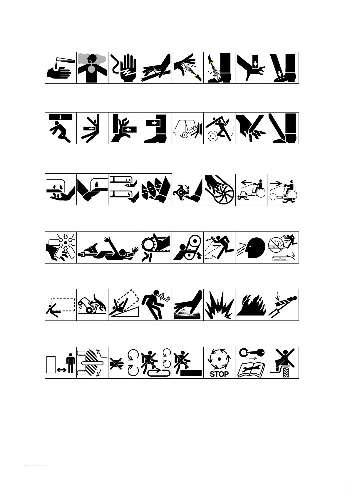
Symbol Glossary
Caustic liquids,
chemical burns to
fingers or hand
Crushing of
whole body,
applied from
above
Severing of
fingers or hand,
mower blade
Poisonous
fumes or toxic
gases, asphyxiation
Crushing of
torso, force
applied from side
Severing of
toes or foot,
mower blade
Electrical shock,
electrocution
Crushing of fingers
or hand/, force
applied from side
Severing of
toes or fingers,
rotary mower
blade
High pressure
fluid, injection
into body
force applied
from side
Cutting or
entanglement of
foot, rotating auger
High pressure
spray, erosion of
flesh
Crushing of
whole body
Severing of
foot, rotating
knives
Crushing of
head, torso and
arms
Severing of
fingers or hand,
impeller blade
High pressure
spray, erosion of
flesh
Crushing of
fingers
force
above
Dismemberment, front engine
mower in forward
motion
or hand,
applied from
Cutting of
fingers or hand
Crushing of
toes or foot, force
applied from above
Cutting of footCrushing of leg,
Dismemberment, front engine
mower in rearward
motion
Severing of
fingers or hand,
engine fan
Runover/backover, vehicle
Stay a safe
distance from
the machine
Whole body entanglement,
implement input drive line
Machine
tipping, riding
mower
Stay clear of
articulation area
while engine is
running
Fingers or
hand entanglement, chain
drive
Machine rollover,
ROPS (rear
engine mower)
Do not open
or remove safety
shields while
engine is
running
Stored energy
hazard, kickback
or upward motion
Do not step on
loading platform
if PTO is connected to tractor &
engine is running
Hand & arm
entanglement,
belt drive
Hot surfaces,
burns to fingers
or hands
Do not step Wait until all
Thrown or flying
objects, whole
body exposure
Explosion Fire or open
machine components have
completely
stopped before
touching them
Thrown or
flying objects,
face exposure
flame
Shut off engine
& remove key
before performing maintenance
or repair work
Thrown or flying
objects, rotary
mover
Secure lifting
cylinder with locking
device before getting
in hazardous area
Riding on this
machine is allowed
only on a passenger seat & only if the
driver’s view is not
hindered
6
Page 7

Consult technical
manual for proper
service
procedures
Fasten seat
belts
Safety alert
triangle
Outline safety
alert symbol
Read operator’s
manual
Fire, open light
and smoking
prohibited
Eye protection
must be worn
Head protection
must be worn
Brake system
Filter Temperature Failure/
Plus/increase/
positive polarity
Hearing
protection must
be worn
Oil Coolant (water) Intake air Exhaust gas Pressure Level indicator Liquid level
Minus/decrease/
negative polarity
Caution, toxic
risk
Malfunction
Horn
Flush with water Engine Transmission Hydraulic systemFirst aid
Start switch/
mechanism
Battery charging
condition
Hourmeter/
elapsed operating
hours
On/start Off/stop Engage
Fast Slow Continuous
Disengage
variable, linear
Volume empty Volume full Machine travel
Oil lubrication
point
Engine lubricating
oil temperature
Lift point Jack or
Engine coolant
direction,
forward/
rearward
support point
Engine coolant
pressure
Control lever
operating
direction, dual
direction
Draining/
emptying
Engine coolant
filter
Control lever
operating
direction, multiple
direction
Engine lubricating oil
Engine coolant
temperature
Clockwise
rotation
Engine
lubricating
oil pressure
Engine intake/
combustion air
Counter-clockwise rotation
Engine lubricating
oil level
Engine intake/combustion air pressure
Grease
lubrication
point
Engine lubricating
oil filter
Engine intake/air
filter
7
Page 8

Engine start Engine stop Engine failure/
Transmission
oil pressure
Transmission
oil temperature
malfunction
Transmission
failure/malfunction
RP 231
Reverse
Park First gear
n/min
Engine rotational
speed/frequency
Choke Primer (start aid) Electrical preheat
(low temperature
start aid)
Transmission
oil
NHLF
Clutch Neutral High Low Forward
Second gear
Third gear (other #'s
may be used until the
maximum # of forward
gears is reached.)
Hydraulic oil
Hydraulic oil
pressure
Hydraulic oil
level
Hydraulic oil
filter
Power Take-Off,
rotational speed
Cutting unit,
transport
position
Hydraulic oil
temperature
Blade cutting
element
Cutting unit,
raise to transport
position
Hydraulic oil
failure/malfunction
Blade cutting
element, height
adjustment
Cutting unit,
lower to transport
position
Parking brake Fuel
Lock Unlock Differential lock 4-Wheel drive Power Take-OffDiesel fuel Unleaded fuel Headlights
Attachment
lower
Cutting unit Cutting unit,
raise
Attachment
raise
Fuel level
Cutting unit,
lower
Spacing distance Snow thrower,
Fuel filter Fuel system
Cutting unit,
hold
collector auger
failure/malfunction
Cutting unit,
float
Traction
Above working
temperature
range
8
Drilling Manual metal
arc welding
Manual Water pump Keep dry Weight Do not dispose
in the garbage
CE logo
Page 9

Before Operating
CHECK LUBRICANT IN GEAR BO X
(Fig. 1)
The gear box is designed to operate with SAE 80-90 wt.
gear lube. Although the gear box is shipped with lubricant
from the factory, check the level before operating the cutting
unit.
1. Position the machine and cutting unit on a level sur-
face.
2. Remove the check plug from the side of the gear box
and make sure the lubricant is up to the bottom of the
hole. If the lubricant level is low, remove the fill plug
on top of the gear case and add enough lubricant to
bring it up to the bottom of the hole in the side.
ADJUSTING HEIGHT OF CUT (Fig. 2–5)
Figure 1
1. Filler Plug
2. Check Plug
The height of cut is adjustable from 2.5 to 12.7 cm in 2.5
cm increments.
1 Start the engine and raise the cutting unit. Stop the
engine after the cutting unit is raised.
2. Remove front snapper pins from castor arms and slide
castor wheel assembly up or down.
3. Insert the snapper pin into the castor arm and through
the groove in the castor shaft to get the desired height
of cut
4. Remove hair pin cotter and clevis pin securing height-of-
cut straps to rear of deck.
5. Mount the height-of-cut straps to desired height-of-cut
hole with the clevis pin and hair pin cotter.
6. When using 2.5 cm height of cut, move skids, rollers,
and wing wheels to the highest holes.
Figure 2
1. Snapper Pin
Figure 3
ADJUSTING SKIDS (Fig. 4)
Skids should be located in upper holes for 2.5 and 3.8 cm
heights of cut and lower holes for 5 to 12.7 cm heights of
cut.
1. Adjust skids by removing flange nuts, positioning as
desired and installing the flange nuts.
Figure 4
1. Height-of-cut chain
9
Page 10

ADJUSTING ROLLERS (Fig.6)
Rollers should be located in the upper holes for 2.5 and 3.8
cm heights of cut and lower holes for 5 to 12.7 cm heights
of cut. Five rollers are located on the deck, three under the
main deck and one on each wing.
1. Adjust the rollers by removing the lock nut and bolt,
positioning as desired and then installing the lock nut
and bolt.
ADJUSTING DECK PITCH(Fig. 7)
Figure 5
Deck pitch is the difference in height of cut from the front of
the blade plane to the back of the blade plane. TORO recommends a blade pitch of 6.4 mm ,i.e., the back of the blade
plane is .6.4 mm higher than the front.
1. Position the machine on a level surface on the shop
floor.
2. Set the deck to the desired height of cut.
3. Rotate (1) blade so it points straight forward.
4. Using a short ruler, measure from the floor to the front
tip of the blade and remember this dimension. Then,
measure from the floor to the rear tip of the blade.
5. Subtract the front dimension from rear dimension to
calculate the pitch.
6. To adjust pitch, start the tractor and raise the deck to
the highest possible position and turn off the engine.
7. Loosen the jam nuts on the bop or bottom of the height-
of-cut chain U bolt.
2
1
Figure 6
1. Skid
2. Roller
Figure 7
1. Height-of-cut chain
2. U bolt
8. Adjust the other set of nuts to raise or lower the rear of
the No. 3 chamber and attain the correct deck pitch.
9. Tighten the jam nut.
10. Lower the deck.
10
Page 11

Operating Instructions
OPERA TING TIPS
1. Mow When Grass Is Dry—Mow either in the late
morning to avoid the dew, which causes grass clumping
or in late afternoon to avoid the damage that can be
caused by direct sunlight on the sensitive, freshly
mowed grass.
2. Select The Proper Height-of-Cut Setting To Suit
Conditions— Remove one inch or no more than 1/3 of
the grass blade when cutting. In exceptionally lush and
dense grass you may have to raise your height of cut to
the next setting.
3. Mow At Proper Intervals—Under most normal conditions you'll need to mow every 4–5 days. But remember, grass grows at different rates at different times.
This means that to maintain the same height of cut,
which is a good practice, you'll need to cut more frequently in early spring; as the grass growth rate slows
in mid summer, cut only every 8–10 days. If you are
unable to mow for an extended period due to weather
conditions or other reasons, mow first with the height
of cut at a high level; then mow again 2–3 days later
with a lower height setting.
4. Always Mow With Sharp Blades—Asharp blade cuts
cleanly and without tearing or shredding the grass
blades like a dull blade. Tearing and shredding causes
the grass to turn brown at the edges which impairs
growth and increases susceptibility to diseases.
CAUTION: This product may exceed noise levels of
85 dB(A) at the operator position. Ear protectors
are recommended for prolonged exposure to reduce
the potential of permanent hearing
damage.
5. Transporting—Use the transporting latch when trans-
porting over long distances or in rough terrain.
6. Trailering—When loading or unloading the machine
from a trailer, disconnect the rear height-of-cut chains
to allow maximum deck rotation.
7. After Operating—To assure optimum performance,
clean the underside of the mower housing after each
use. If residue is allowed to build up in the mower
housing and on inserts, cutting performance will
decrease.
11
Page 12

8. Deck Pitch—Toro recommends a blade pitch of 6.4
mm. Apitch larger than 6.4 mm will result in less
power required, larger clippings and a poorer quality
Maintenance
of cut. Apitch less than 6.4 mm will result in more
power required, smaller clippings and a better quality of cut.
LUBRICATION
GREASE BEARINGS, BUSHINGS AND GEAR
BOX (Fig.8)
The cutting unit must be lubricated regularly. If the
machine is operated under normal conditions, lubricate
the castor bearings and bushings with No. 2 general purpose lithium base grease or molybdenum base grease,
after every 8 hours of operation or daily, whichever
comes first. Lubricate fittings immediately after every
washing, regardless of the interval listed.
1. The cutting unit has bearings and bushings that
must be lubricated, and these lubrication points are:
gage wheels (2) (Fig. ), front castor shaft bushings
(2), blade spindle bearings (5), idler arm pivots (2),
drive shaft (3), Wing deck pivots (2) and right and
left push arm ball joints (Fig. 8).
2. Position the machine and cutting unit on a level
surface and lower the cutting unit. Remove the
check plug from the side of gear box and make sure
lubricant is up to the bottom of the hole. If the
level of lubricant is low, remove the fill plug on top
of the gear case and add SAE 80-90 wt. gear lube
until the level is up to the bottom of hole in side.
Fig. 8
1
2
Figure 9
1. Filler plug
2. Check/Drain plug
12
Page 13

CAUTION
To prevent accidental starting of the engine while performing maintenance, shut of the engine and remove
the key from the ignition switch.
DISCONNECTING THE CUTTING
UNIT FROM THE TRACTION UNIT
(Fig. 10–12)
Note: Implements are heavy and may require two people to
handle.
1. Start the tractor and raise the deck to the highest possible position and turn off the engine.
2. Remove the hair pin cotter and clevis pin securing the
height-of-cut straps to the rear height-of-cut brackets.
3. Turn the ignition key to the run position and move the
lift lever forward to lower the cutting unit.
4. Raise the seat and open the needle valve. This allows
the lift arms to float freely.
5. Remove the hair pin cotter and clevis pin securing the
latch cover to the lift arm .
6. Loosen the release lever by rotating it counterclockwise.
7. Pivot the release lever upward and remove the shaft
latch from the slot in the traction unit lift arm.
Figure 10
1. Height-of-cut chain
Figure 11
1. Needle Valve
8. Pull rearward on the lock collar to release the drive
shaft coupler from the tractor.
9. Stay clear of lift arms and move the deck away from
the tractor, allowing the lift arms to fall.
10. Secure the hair pin cotter and clevis pin to height-of-cut
straps for storage.
11. Close the needle valve
CONNECTING THE CUTTING UNIT
TO THE TRACTION UNIT
1. Center the traction unit in front of the cutting unit on
any flat hard surface.
(Fig. 9–11
Figure 11
1. Latch Cover 4. Traction Unit lift Arm
2. Release Lever 5. Machined Surface
3. Shaft latch
13
Page 14

2. Raise the seat and open the needle valve. This
allows the lift arms to float freely.
8. Move the deck from side to side to check for tight-
ness and re-tighten the latches, if required.
3. Adjust the lift arms heights, making sure that the
machined surface on top of each traction unit lift
arm is parallel to the ground (Fig. 11). (Raise or
lower the lift arm casting by pushing up or down
from behind the front tires or by using a wrench in
front of the tractor)
4. Check for dirt and debris on mating parts and clean
as required.
5. Turn the castor wheels so they point straight for-
ward and the deck moves easily toward the tractor.
6. Secure the first lift arm assembly to the traction
unit as follows:
A. Remove the hair pin cotter and clevis pin
securing the latch cover to the lift arm.
B. Pivot the release lever upward.
C. Slide the cutting unit lift arm onto the traction
unit lift arm, inserting the shaft latch into the
slot in the traction unit lift arm.
9. Install the latch covers to the lift arms and secure
them with clevis pins and hair pin cotters.
10. Connect the drive shaft to the traction unit.
11. Close the needle valve and lower the seat.
12. Start the tractor and raise the deck to the highest
possible position. Then turn off the engine.
13. Align the height-of-cut straps with the hole for
desired height of cut, install the clevis pin and
secure it with a hair pin cotter.
CHANGING GEAR BO X
LUBRICANT
The gear box lubricant must be changed initially after
the first 400 hours of operation, and subsequently after
every 1600 hours of operation.
1. Position the machine and cutting unit on a level sur-
face.
(Fig. 13)
Note: If the latch does not fall into the slot in
the traction unit lift arm, raise or lower the lift
arm casting by pushing up or down from
behind the front tires.
D. Pivot the release lever downward and tighten
securely by rotating clockwise.
7. Install the other lift arm on the tractor by rotating
the deck toward tractor, aligning the lift arm to
tractor arm and repeating step 5. If the latch does
not fall into the slot in the traction unit lift arm, the
arms are not lined up.
A. If the lift arms on the traction unit are not at
the correct height for deck arms to slide on,
push up or down on the lift arm castings from
behind the front tires until deck arms line up
and slide on.
B. If lift arms on deck do not line up side to side,
rotate the castor wheels side ways so the deck
moves easier from side to side. Move the
deck side to side until the lift arms line up and
slide on.
2. Loosen the fixed idler pulley locking nut.
3. Loosen the spring tensioning nut and remove the
belt.
4. Remove the four (4) locknuts securing the gearbox
mount to the deck.
5. Remove the belt from the pulley.
6. Remove the check plug from the side of the gear
box and tip the gear box assembly, allowing lubricant to drain from the gear box.
7. Install the belt to the pulley.
8. Install the gear box assembly to the deck.
9. Remove the fill plug on top of the gear case and add
SAE 80–90 weight gear lube until the level is up to
the bottom of the hole in the side.
10. Install the check plug to the side of the gear box and
the fill pug to the top of the gear case.
11. Re-tension the belt.
14
Page 15

REPLACING DRIVE BELTS (Fig. 14–15)
The blade drive consists of three belts—one main drive belt
and two wing belts. The main drive belt is tensioned by a
fixed idler with a spring adjustment. The wing belts have
spring-loaded idlers. All belts are very durable but after
many hours of use, the belt will show signs of wear. Signs of
a worn belt are: squealing when belt is rotating, blades slipping when cutting grass, frayed edges, burn marks and
cracks. Replace any belt if any of these conditions are evident. Adjust belt tension on main belt after 10 hours of operation to assure maximum durability.
1. Lower the cutting unit to the shop floor. Remove the
belt covers from the top of the cutting unit and set the
covers aside.
2. Pull on the spring loaded idlers and remove the wing
belts.
3. Loosen the fixed idler pulley locking nut.
4. Loosen the spring tensioning nut as required and
remove the belt.
Figure 13
1. Gear box mount
2. Filler plug
3. Check plug
5. Route new belts around the spindle pulleys and through
the idler pulley assemblies as shown in figure 15.
6. Tighten the spring tensioning nut until the spring length
is 9.9 cm inside the spring loops(Fig. 14).
7. Tighten the idler pulley locking nut.
8. Pull on the spring loaded idlers and install wing belts.
9. Install belt covers to top of the cutting unit.
SER VICING THE FRONT BUSHINGS
IN THE CAST OR FORKS
The castor forks have bushings pressed into the top and bottom of the casting and after many hours of operation, the
bushings will wear. To check the bushings, move the castor
fork back and forth and from side to side. If the castor spindle is loose around the bushings, the bushings are worn and
must be replaced.
(Fig. 16)
Figure 14
1. Idler pulley
2. Spring tensioning nut
3. Idler pulley locking nut
Figure 15
1. Start the tractor and raise the deck to the highest possible position and turn off the engine.
2. Remove the front snapper pins from the castor arms and
slide the castor wheel assembly out of the castor arm
15
Page 16

tube.
3. Remove the locknut from the capscrew holding the cas-
tor wheel assembly between the castor fork. Grasp the
castor wheel and slide the capscrew out of the fork.
4. Remove the retaining ring, washer and wavy washer
securing the castor shaft to the castor fork. Remove the
shaft from the fork.
5. Insert a pin punch into the top or bottom of the castor
fork and drive the bushing out of the fork. Repeat for
the other bushing. Clean inside of the forks to remove
dirt.
6. Apply grease to the inside and outside of the new bush-
ings. Using a hammer and flat plate, drive the bushings
into the fork.
7. Inspect the castor shaft and fork for wear and replace if
damaged.
8. Push the castor shaft through bushings and fork and
secure with wavy washer, washer and retaining ring.
9. Insert snapper pin into the castor arm and through the
groove in the castor shaft at the desired height of cut.
Figure 16
1. Front castor fork
2. Retaining ring
3. Washer
4. Wavy washer
5. Castor shaft
6. Bushings
SER VICING CAST OR WHEELS AND
BEARINGS
The castor wheel rotates on a high-quality roller bearing.
Even after many hours of use, provided that the bearing was
kept well-lubricated, bearing wear will be minimal.
However, failure to keep the bearing lubricated will cause
rapid wear. A wobbly castor wheel usually indicates a worn
bearing.
1. Remove the locknut from the capscrew holding the cas-
tor wheel assembly between the castor fork. Grasp the
castor wheel and slide the capscrew out of the fork.
2. Remove the bearing from the wheel hub and allow the
spacer to fall out. Remove the bearing from the opposite side of the wheel hub.
3. Check the bearings, spacer and inside of the wheel hub
for wear. Replace defective parts as required.
4. To assemble the castor wheel, push the bearing into the
wheel hub. Slide the spacer into the wheel hub. Push
the other bearing into open end of the wheel hub to
captivate the spacer inside the wheel hub.
(Fig. 17)
Figure 17
1. Bearing
2. Spacer
16
Page 17

5. Install the castor wheel assembly between the castor
forks and secure in place with capscrew and locknut.
REMO VING CUTTER BLADE (Fig.18)
The blade must be replaced if a solid object is hit, the blade
is out of balance or if the blade is bent. Always use genuine
TORO replacement blades to be sure of safety and optimum
performance. Never use replacement blades made by other
manufacturers because they could be dangerous.
WARNING
Do not try to straighten a blade that is bent, and never
weld a broken or cracked blade. Always use a new
blade to assure continued safety certification of the
product.
1. Raise the cutting unit to the highest position, shut the
engine off and engage the parking brake.
2. Remove the hair pin cotters and clevis pins securing the
height-of-cut straps to the rear of the deck.
3. Rotate the front of the deck upward and insert the latch
rod into the front hole (service position) in the latch
plate.
4. Grasp the end of the blade using a rag or thickly
padded glove. Remove the blade bolt, cup and blade
from the spindle shaft.
5. Install blade sail facing (up) toward the cutting unit
with the cup and blade bolt. Tighten the blade bolt to
115–145 Nm.
Figure 18
1. Blade bolt
2. Cup
Figure 19
1. Sail
2. Wear
3. Slot formed
1
INSPECTING AND SHARPENING
THE BLADE
1. Raise the cutting unit to the highest position, shut the
engine off and engage the parking brake.
2. Remove the hair pin cotters and clevis pins securing the
height of-cut straps to the rear of the deck.
3. Rotate the front of the deck upward and insert the latch
rod into the front hole (service position) in the latch
plate.
4. Examine the cutting ends of the blade carefully, especially where the flat and curved parts of the blade meet
(Fig. 19-A). Since sand and abrasive material can wear
(Flg. 19–20)
2
2
Figure 20
1. Sharpen at this angle only
2. End view
17
Page 18

away the metal that connects the flat and curved
parts of the blade, check the blade before using the
machine. If wear is noticed (Fig. 19-B), replace the
blade: refer to Removing The Cutter Blade.
4. Position the tip of the outer blade and adjacent
blade tip as close together as possible at the intersection of the two cutting chambers. Note the
height of the outer blade tip with respect to the
height of the adjacent blade tip.
DANGER
If the blade is allowed to wear, a slot will form
between the sail and flat part of the blade (Fig. 17C). Eventually a piece of the blade may break off
and be thrown from under the housing, possibly
resulting in serious injury to yourself or a
bystander.
5. Inspect the cutting edges of all blades. Sharpen the
cutting edges if they are dull or nicked. Sharpen
only the top of the cutting edge and maintain the
original cutting angle for best performance (Fig.
20). The blade will remain balanced if the same
amount of metal is removed from both cutting
edges.
6. To check the blade for being straight and parallel,
lay the blade on a level surface and check its ends.
Ends of the blade must be slightly lower than the
center, and the cutting edge must be lower than the
heel of the blade. This blade will produce good
quality of cut and require minimal power from the
engine. By contrast, a blade that is higher at the
ends than the center, or that has a cutting edge
higher than the heel, is bent or warped and must be
replaced.
7. Install the blade sail facing (up) toward the cutting
unit with cup and blade bolt. Tighten blade bolt to
115–149Nm.
5. Rotate the outer blade 180° and note the height of
the outer blade tip with respect to the height of the
adjacent blade tip. If the relative height changed by
more than 3 mm after rotating the blade, then the
outer blade is bent and should be replaced..
6. Repeat steps 4 and 5 until all pairs of adjacent
blades have been checked at both blade tips. Note
the relative difference in blade height at each blade
intersection after replacing any bent blades. This
height difference should be less than 3 mm for all
adjacent blades.
7. ‘Raise the height-of-cut to the highest position and
lower the deck to the floor.
8. Rotate an outer blade until the tip is positioned
nearest to the skid on the side of the deck housing.
Measure the distance from the bottom of the blade
to the floor. Repeat the measurement on the opposite side of the deck. If the two measurements differ by more than 6 mm, go to step 9 and add shims
as instructed.
9. Remove the capscrews, flatwashers, lockwashers
and nuts from the outer spindle in the area where
shims must be added. To raise or lower the blade,
add a ship, Part No. 3256-24, between the spindle
housing and the bottom of the cutting unit.
Continue to check the alignment of the blades and
add shims until the tips of the blades are within the
required dimension.
CORRECTING CUTTING UNIT
MISMATCH
If there is mismatch between the blades, the grass will
appear streaked when it is cut. This problem can be corrected by making sure the blades are straight and all
blades are cutting on the same plane.
1. Position the machine on a level surface on the shop
floor.
2. Release the belt tension on the belts.
3. Raise the deck to the transport position and lock
the transport latch.
18
IMPORTANT: Do not use more than three shims
at any individual hole location. Use decreasing
numbers of shims in adjacent holes if more than
one shim is added to a hole location.
10. Re-tension the belts. Reinstall the belt covers.
IDENTIFICATION AND ORDERING
MODEL AND SERIAL NUMBERS
The cutting deck has two identification numbers: a
model number and a serial number. The two numbers
Page 19

are stamped into a plate on the front channel of the mower
deck, under cover. In any correspondence concerning the
mower, supply the model and serial numbers to assure that
correct information and replacement parts are obtained.
To order replacement parts from an authorized TORO
Distributor, supply the following information:
1. Model and serial numbers of the machine.
2. Part number, description and quantity of parts desired.
Note: Do not order by reference number if a parts catalog is
being used; use the part number.
19
Page 20

 Loading...