

Page 1
FormNo.3358-665RevA
PolarTracGroundsmaster
Tractor
ModelNo.30383—SerialNo.270000001andUp
®
7210
Registeratwww.T oro.com.OriginalInstructions(EN)
Page 2
Warning
CALIFORNIA
Proposition65Warning
Dieselengineexhaustandsomeofits
constituentsareknowntotheStateof
Californiatocausecancer,birthdefects,
andotherreproductiveharm.
Becauseinsomeareastherearelocal,state,orfederal
regulationsrequiringthatasparkarresterbeusedonthe
engineofthismachine,asparkarresterisavailableas
anoption.Ifyourequireasparkarrestor,contactyour
AuthorizedServiceDealer.
GenuineTorosparkarrestersareapprovedbytheUSDA
ForestryService.
Important:ItisaviolationofCaliforniaPublic
ResourceCodeSection4442touseoroperate
theengineonanyforest-covered,brush-covered,
orgrass-coveredlandwithoutasparkarrester
mufermaintainedinworkingorder,ortheengine
constricted,equipped,andmaintainedforthe
preventionofre.Otherstatesorfederalareasmay
havesimilarlaws.
Introduction
Readthisinformationcarefullytolearnhowtooperate
andmaintainyourproductproperlyandtoavoidinjury
andproductdamage.Youareresponsibleforoperating
theproductproperlyandsafely.
YoumaycontactTorodirectlyatwww .Toro.comfor
productandaccessoryinformation,helpndinga
dealer,ortoregisteryourproduct.
Wheneveryouneedservice,genuineToroparts,
oradditionalinformation,contactanAuthorized
ServiceDealerorToroCustomerServiceandhave
themodelandserialnumbersofyourproductready .
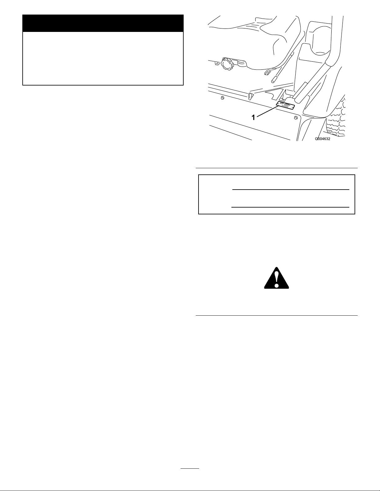
Figure1identiesthelocationofthemodelandserial
numbersonthetractionunit.Themodelandserial
numbersforthecabareprintedonaplatelocatedon
insidethecab,ontheframeabovethedoor.Writethe
numbersinthespaceprovided.
Figure1
1.Modelandserialnumberlocation
ModelNo.
SerialNo.
Thismanualidentiespotentialhazardsandhas
safetymessagesidentiedbythesafetyalertsymbol
(Figure2),whichsignalsahazardthatmaycauseserious
injuryordeathifyoudonotfollowtherecommended
precautions.
Figure2
1.Safetyalertsymbol
Thismanualalsouses2wordstohighlightinformation.
Importantcallsattentiontospecialmechanical
informationandNoteemphasizesgeneralinformation
worthyofspecialattention.
©2007—TheToro®Company
8111LyndaleAvenueSouth
Bloomington,MN55420
Contactusatwww.Toro.com.
2
PrintedintheUSA.
AllRightsReserved
Page 3

Contents
Introduction.................................................................2
Safety...........................................................................4
SafeOperatingPractices.......................................4
SlopeChart..........................................................6
SafetyandInstructionalDecals.............................7
Setup..........................................................................11
1CheckingtheTirePressure...............................11
2CheckingFluidLevels......................................11
ProductOverview......................................................12
Controls.............................................................12
Specications.....................................................15
Attachments/Accessories...................................15
Operation...................................................................15
AddingFuel.......................................................15
CheckingtheEngineOilLevel............................16
CheckingtheCoolingSystem..............................16
CheckingtheHydraulicSystem...........................16
ThinkSafetyFirst...............................................17
OperatingtheParkingBrake...............................17
StartingtheEngine.............................................18
DrivingtheMachine...........................................18
StoppingtheMachine/Engine............................19
OperatingAttachments......................................20
TheSafetyInterlockSystem................................21
PositioningtheSeat............................................22
UnlatchingtheSeat.............................................23
MovingaNon-functioningMachine...................23
LoadingMachines..............................................24
TransportingtheMachine...................................25
Maintenance...............................................................26
RecommendedMaintenanceSchedule(s)................26
DailyMaintenanceChecklist...............................27
Lubrication.............................................................28
GreasingtheBearingsandBushings....................28
EngineMaintenance...............................................29
AirCleanerMaintenance....................................29
ServicingtheEngineOil.....................................30
FuelSystemMaintenance.......................................31
ServicingtheWaterSeparator.............................31
CleaningtheFuelTank.......................................32
ReplacingtheFuelPre-Filter...............................32
FuelLinesandConnections................................32
BleedingtheFuelSystem....................................32
BleedingAirFromtheInjectors..........................33
ElectricalSystemMaintenance................................34
ServicingtheBattery...........................................34
StoringtheBattery..............................................34
CheckingtheFuses.............................................34
DriveSystemMaintenance.....................................36
CheckingtheTirePressure.................................36
CoolingSystemMaintenance..................................36
CheckingtheCoolingSystem.............................36
CleaningtheRadiator.........................................37
BrakeMaintenance.................................................37
AdjustingtheParkingBrakeInterlock
Switch............................................................37
BeltMaintenance....................................................38
CheckingtheAlternatorBeltTension..................38
ControlsSystemMaintenance.................................39
AdjustingtheControlLeverNeutralInterlock
Switch............................................................39
AdjustingtheControlLeverNeutral
Return............................................................39
AdjustingtheTractionDriveforNeutral.............40
AdjustingtheMaximumGroundSpeed..............41
AdjustingtheTracking........................................42
HydraulicSystemMaintenance...............................43
CheckingtheHydraulicFluidLevel.....................43
ChangingtheHydraulicOilAndFilter................43
CabMaintenance....................................................44
Storage.......................................................................45
Machine.............................................................45
Engine...............................................................45
Schematics.................................................................46
3
Page 4

Safety
ThismachinemeetsorexceedANSIB71.4-2006
specicationsineffectatthetimeofproduction.
◊lackofawarenessoftheeffectofground
conditions,especiallyslopes;
◊incorrecthitchingandloaddistribution.
Improperuseormaintenancebytheoperatoror
ownercanresultininjury.Toreducethepotential
forinjury,complywiththesesafetyinstructionsand
alwayspayattentiontothesafetyalertsymbol,which
meansCaution,Warning,orDanger—personalsafety
instruction.Failuretocomplywiththeinstructionmay
resultinpersonalinjuryordeath.
SafeOperatingPractices
ThefollowinginstructionsareadaptedfromANSI
B71.4-2006.
Thisproductiscapableofamputatinghandsand
feetandthrowingobjects.Alwaysfollowallsafety
instructionstoavoidseriousinjuryordeath.
Important:Refertothe
Man ual
foradditionalcabsafetyinformation.
Training
•ReadtheOperator’ sManualandothertrainingmaterial
carefully.Befamiliarwiththecontrols,safetysigns,
andtheproperuseoftheequipment.
•Neverallowchildrenorpeopleunfamiliarwiththese
instructionstousethemachine.Localregulations
canrestricttheageoftheoperator.
•Neveroperatewhilepeople,especiallychildren,or
petsarenearby .
•Keepinmindthattheoperatororuserisresponsible
foraccidentsorhazardsoccurringtootherpeopleor
theirproperty.
•Donotcarrypassengers.
•Alldriversshouldseekandobtainprofessional
andpracticalinstruction.Suchinstructionshould
emphasize:
–theneedforcareandconcentrationwhen
workingwithride-onmachines;
–controlofaride-onmachineslidingonaslope
willnotberegainedbytheapplicationofthe
controllevers.Themainreasonsforlossof
controlare:
◊insufcienttrackgrip,especiallyonwetgrass,
iceorsnow;
◊beingdriventoofast;
◊inadequatebraking;
◊thetypeofmachineisunsuitableforitstask;
R OPS Hard Ca b Operator’ s
Preparation
•Whileoperating,alwayswearsubstantialfootwear
andlongtrousers.Donotoperatetheequipment
whenbarefootorwearingopensandals.
•Thoroughlyinspecttheareawheretheequipment
istobeusedandremoveallobjectswhichmaybe
thrownbythemachine.
•Warning-Fuelishighlyammable.
–Storefuelincontainersspecicallydesignedfor
thispurpose.
–Refueloutdoorsonlyanddonotsmokewhile
refueling.
–Addfuelbeforestartingtheengine.Never
removethecapofthefueltankoraddfuelwhile
theengineisrunningorwhentheengineishot.
–Iffuelisspilled,donotattempttostartthe
enginebutmovethemachineawayfromthe
areaofspillageandavoidcreatinganysourceof
ignitionuntilfuelvaporshavedissipated.
–Replaceallfueltankandcontainercapssecurely.
•Replacefaultysilencers/mufers.
•Beforeusing,alwaysvisuallyinspecttoseethatthe
attachmentsarenotwornordamaged.Replaceworn
ordamagedcomponents.
Operation
•Bealert,slowdownandusecautionwhenmaking
turns.Lookbehindandtothesidebeforechanging
directions.
•Engineexhaustcontainscarbonmonoxide,which
isanodorless,deadlypoisonthatcankillyou.Do
notrunengineindoorsorinanenclosedareawhere
fumescancollect.
•Operateonlyindaylightoringoodarticiallight.
•Beforeattemptingtostarttheengine,disengageall
attachmentclutchesandplacethecontrolleversin
theneutral,lockedposition.
•Whenoperatingneardrop-offsorbodiesofwater,
donotuseonslopesgreaterthan15degrees.
•Usecarewhenpullingloadsorusingheavy
equipment.
–Useonlyapproveddrawbarhitchpoints.
–Limitloadstothoseyoucansafelycontrol.
4
Page 5

–Donotturnsharply.Usecarewhenreversing.
–donotstoporstartsuddenlywhenonaslope;
•Watchoutfortrafcwhencrossingornearroadways.
•Whenusinganyattachments,neverdirectdischarge
ofmaterialtowardbystandersnorallowanyonenear
themachinewhileinoperation.Someattachments,
suchasasnowthrower,arecapableofamputating
handsandfeetandthrowingobjects
•Neveroperatethemachinewithdamagedguards,
shields,orwithoutsafetyprotectivedevicesinplace.
•Donotchangetheenginegovernorsettingsor
overspeedtheengine.Operatingtheengineat
excessivespeedmayincreasethehazardofpersonal
injury.
•Beforeleavingtheoperatorsposition:
–disengagethepowertakeoffandlowerthe
attachments;
–placeinneutralandsettheparkingbrake;
–stoptheengineandremovethekey.
•Ifanattachmentshouldstarttovibrateabnormally,
stopthemachineandcheckimmediatelyforthe
cause.
•Disengagedrivetoattachments,stoptheengine,set
theparkingbrakeandremovetheignitionkey:
–beforeclearingblockagesoruncloggingchute;
–beforechecking,cleaningorworkingonthe
attachment
–afterstrikingaforeignobject.Inspectthe
attachmentfordamageandmakerepairsbefore
restartingandoperatingtheequipment;
–ifthemachinestartstovibrateabnormally(check
immediately).
•Disengagedrivetoattachmentswhentransporting,
notinuseoranytimetheattachmentisintheraised
position.
•Stoptheengineanddisengagedrivetoattachment:
–beforerefuelling;
–beforemakingheightadjustmentunless
adjustmentcanbemadefromtheoperators
position.
•UseonlyToroapprovedattachments.
SlopeOperation
–useslowspeedsonslopesandduringtightturns;
–stayalertforhumpsandhollowsandother
hiddenhazards;
•Donotoperateneardrop-offs,ditches,steepbanks
orwater.Tracksdroppingoveredgescancauseroll
overs,whichmayresultinseriousinjury,deathor
drowning.
•Donotoperateonslopeswhereslipperyconditions
couldreducetractionandcouldcauseslidingand
lossofcontrol.
•Donotmakesuddenturnsorrapidspeedchanges.
•Reducespeedanduseextremecautiononslopes.
•Removeormarkobstaclessuchasrocks,treelimbs,
etc.fromtheoperatingarea.Tallgrasscanhide
obstacles.
•Watchforditches,holes,rocks,dips,andrisesthat
changetheoperatingangle,asroughterraincould
overturnthemachine.
•Avoidsuddenstartswhenoperatinguphillbecause
themachinemaytipbackwards.
•Donotoperateoniceincapableofsupportingthe
weightofthismachine.
MaintenanceandStorage
•Keepallnuts,boltsandscrewstighttobesurethe
equipmentisinsafeworkingcondition.
•Neverstoretheequipmentwithfuelinthetank
insideabuildingwherefumesmayreachanopen
ameorspark.
•Allowtheenginetocoolbeforestoringinany
enclosure.
•Toreducetherehazard,keeptheengine,
silencer/mufer,batterycompartmentandfuel
storageareafreeofgrass,leaves,orexcessivegrease.
•Replacewornordamagedpartsforsafety.
•Ifthefueltankhastobedrained,dothisoutdoors.
•Whenmachineistobeparked,storedorleft
unattended,lowertheattachmentunlessapositive
mechanicallockisused.
•UseonlygenuineTororeplacementpartstoensure
thatoriginalstandardsaremaintained.
•Rememberthereisnosuchthingasasafeslope.
Travelonslopesrequiresparticularcare.Toguard
againstoverturning:
5
Page 6
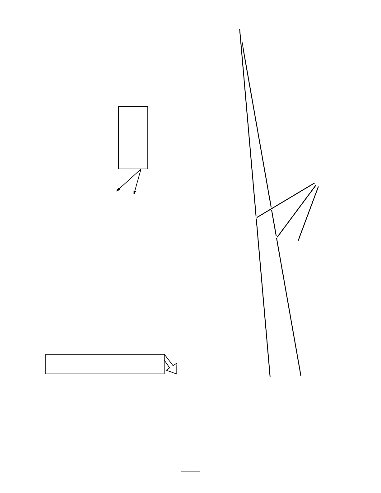
SlopeChart
Fold along appropriate line
Align this edge with a vertical surface
(Tree, Building, Fence post, pole, etc.)
Example: Compare
slope with folded
edge.
THIS IS A 5° SLOPE
THIS IS A 15° SLOPE
THIS IS A 10° SLOPE
6
Page 7
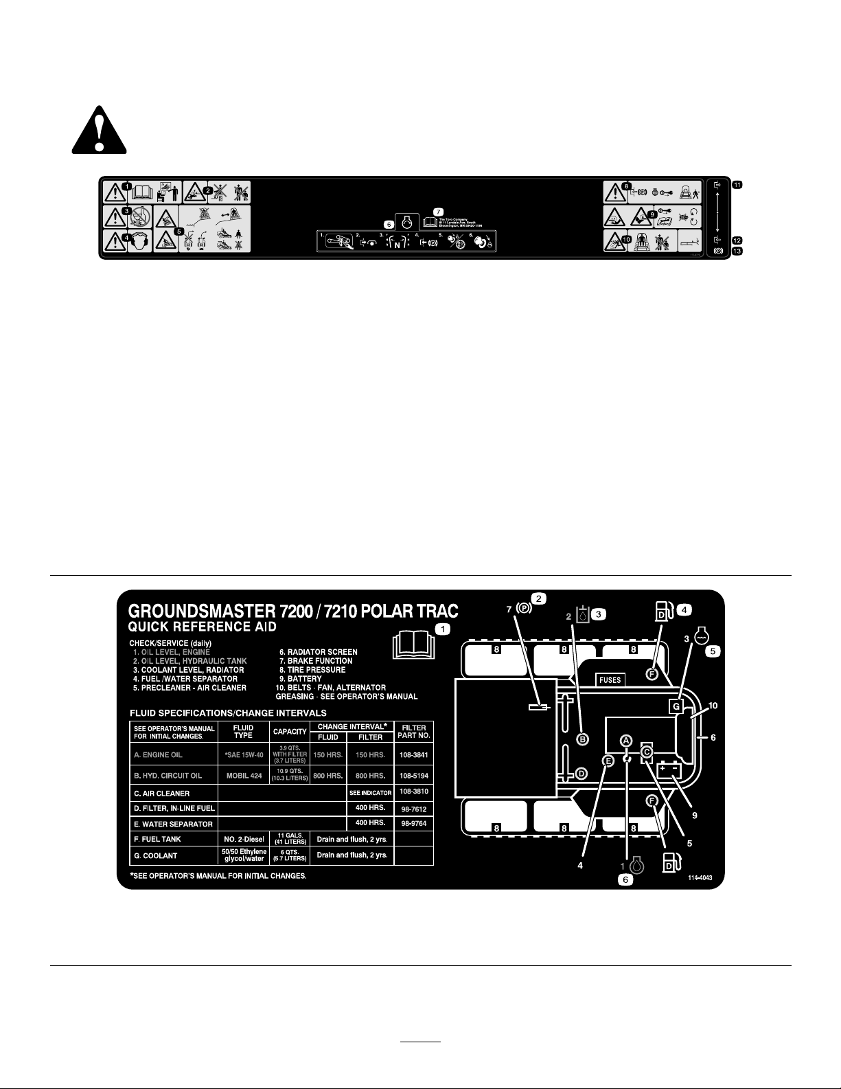
SafetyandInstructional
Decals
Safetydecalsandinstructionsareeasilyvisibletotheoperatorandarelocatednearanyareaof
potentialdanger.Replaceanydecalthatisdamagedorlost.
1.Warning—readtheOperator’sManualbeforeoperatingand
donotoperatethismachineunlessyouaretrained.
2.Crushing/dismembermenthazardofbystanders—donot
carrypassengers,keepbystandersasafedistancefromthe
machine.
3.Warning—donotusedrugsoralcohol.
4.Warning—wearhearingprotection.11.Disengage
5.Tipping,dropoffhazard—donotoperatenearwaterdrop-offs,
stayasafedistancefromdrop-offs,slowmachinebefore
turning,donotturnathighspeeds,wearaseatbeltwhen
aROPSisinplace,donotwearaseatbeltwhenROPSis
lowered.
6.Tostarttheengine:clearanydebrisfromtheattachment,
disengagethePTO,movethemotioncontrolleverstothe
neutralposition,engagetheparkingbrake,turntheignitionto
Runandwaitfortheglowpluglighttoturnoff,turntheignition
keytoStart.
7.ReadtheOperator’sManual.
110-9772
8.Warning—engagetheparkingbrake,stoptheengineand
removetheignitionkeybeforeleavingthemachine.
9.Cuttinghazardofhandorfoot—removetheignitionkey
andreadtheinstructionsbeforeservicingorperforming
maintenance,keepawayfrommovingparts.
10.Thrownobjecthazard—keepbystandersasafedistancefrom
themachine;keepalldeectorsandshieldsinplace.
12.Engage
13.Parkingbrake
114-4043
1.ReadtheOperator’sManual.
2.Parkingbrake4.Fuel6.Engineoil
3.Hydraulicoil5.Enginecoolant
7
Page 8
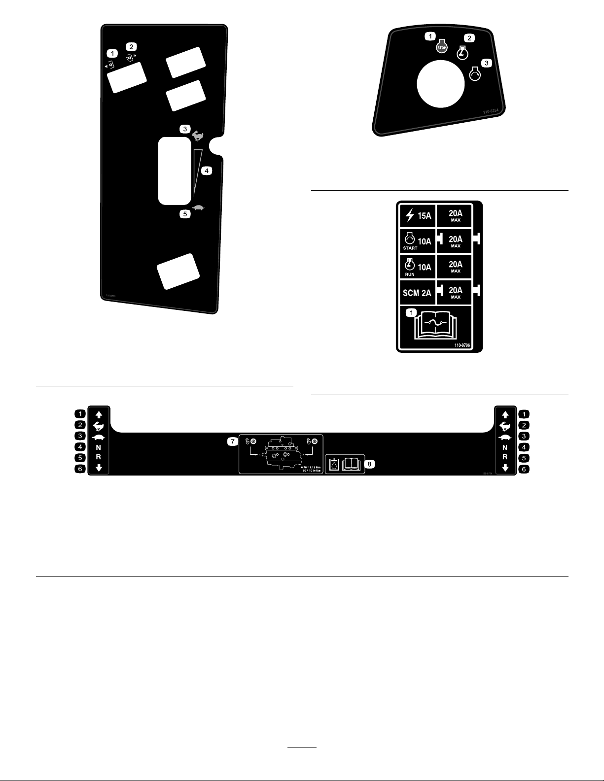
110-8253
1.PTO–Off4.Continuousvariable
setting
2.PTO—On5.Slow
3.Fast
110-8254
1.Engine–Stop3.Engine—Start
2.Engine—Run
110-9796
1.ReadtheOperator’sManualforinformationonfuses.
1.Forward
2.Fast4.Neutral6.Backward
3.Slow
110-9774
5.Reverse7.Towvalvelocation;torque
thetowvalvesto6.78±
1.13N⋅m(60±10in-lbs).
8.ReadtheOperator’s
Manualformore
informationonthehydraulic
oil.
8
Page 9
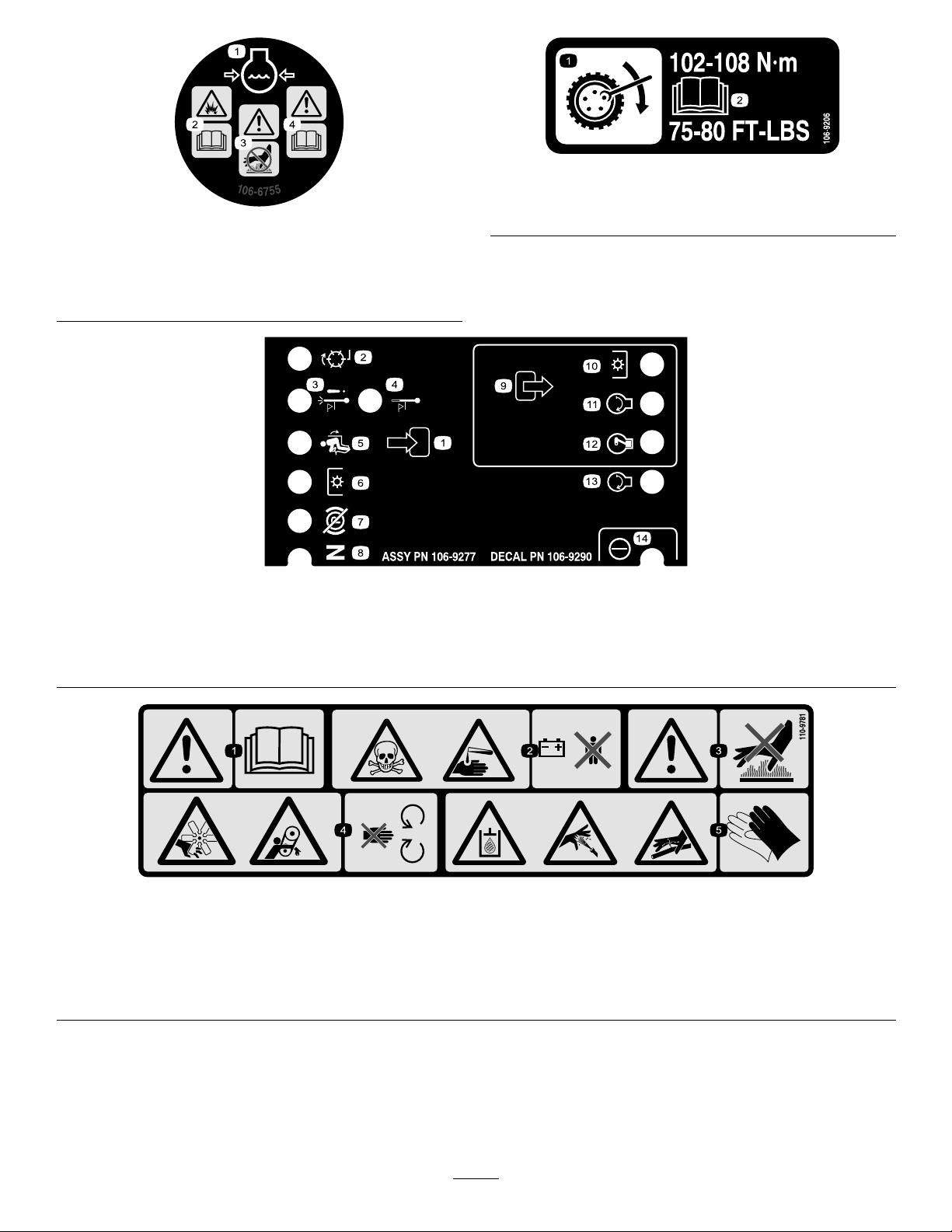
1.Wheeltorquespecications
2.ReadtheOperator’sManual.
1.Enginecoolantunder
pressure.
2.Explosionhazard—read
theOperator’sManual.
106-6755
3.Warning—donottouch
thehotsurface.
4.Warning—readthe
Operator’sManual.
106-9290
1.Inputs5.Inseat
2.(notactiveonthismachine)6.PowerT ake-off(PTO)10.PowerTake-off(PTO)
3.Hightemperatureshutdown
4.Hightemperaturewarning8.Neutral
7.ParkingbrakeOff11.Start
9.Outputs13.Start
12.EnergizetoRun(ETR)
106-9206
14.Power
110-9781
1.Warning—readtheOperator’sManual.
2.Poisonandcausticliquid/chemicalburnhazard—keepchildrenasafedistancefromthebattery.
3.Warning—donottouchthehotsurface.
4.Cutting/dismembermenthazard,fanandentanglementhazard,belt—stayawayfrommovingparts.
5.Hydraulicoilinsystemunderpressure,escapinghydraulicoilpenetratingskinhazard,brokenhydrauliclineshazard—wear
protectivehandprotectionwhenhandlinghydraulicsystemcomponents.
9
Page 10

BatterySymbols
Someorallofthesesymbolsareonyourbattery
1.Explosionhazard
2.Nore,opename,or
smoking.
3.Causticliquid/chemical
burnhazard
4.Weareyeprotection9.Flusheyesimmediately
5.ReadtheOperator’s
Manual.
6.Keepbystandersasafe
7.Weareyeprotection;
8.Batteryacidcancause
10.Containslead;donot
distancefromthebattery.
explosivegasescan
causeblindnessandother
injuries
blindnessorsevereburns.
withwaterandgetmedical
helpfast.
discard.
10
Page 11

Setup
LooseParts
Usethechartbelowtoverifythatallpartshavebeenshipped.
ProcedureDescription
1
2
Nopartsrequired
Nopartsrequired
MediaandAdditionalParts
Description
Operator’sManual
EngineOperator’sManual
PartsCatalog
ROPSHardCabOperator’sManual
OperatorTrainingDVD
Pre-deliveryInspectionSheet
Enginewarranty1
1
CheckingtheTirePressure
NoPartsRequired
Qty.
–
–
Qty.
1
1
1Usetolookupandorderparts.
1
1
1
Readbeforeoperatingthemachine.
Readbeforeoperatingthemachine.
Readbeforeoperatingthemachine.
Viewbeforeoperatingthemachine.
Readtoverifyproperdelivery.
Saveforfutureuse.
2.Checktheengineoillevelbeforeandafterstarting
theengine,refertoCheckingtheEngineOilLevel
inEngineMaintenance.
3.Checkthecoolingsystembeforestartingtheengine;
refertoCheckingtheCoolingSysteminCooling
SystemMaintenance.
Use
Checkthetirepressure.
Checkthehydraulicuid,engineoil,
andcoolantlevels.
Use
Procedure
Ensurethatthetiresareinatedto35psi(241kPa).
2
CheckingFluidLevels
NoPartsRequired
Procedure
1.Checkthehydraulicuidlevelbeforestartingthe
engine,refertoCheckingtheHydraulicFluidLevel
inHydraulicSystemMaintenance.
11
Page 12
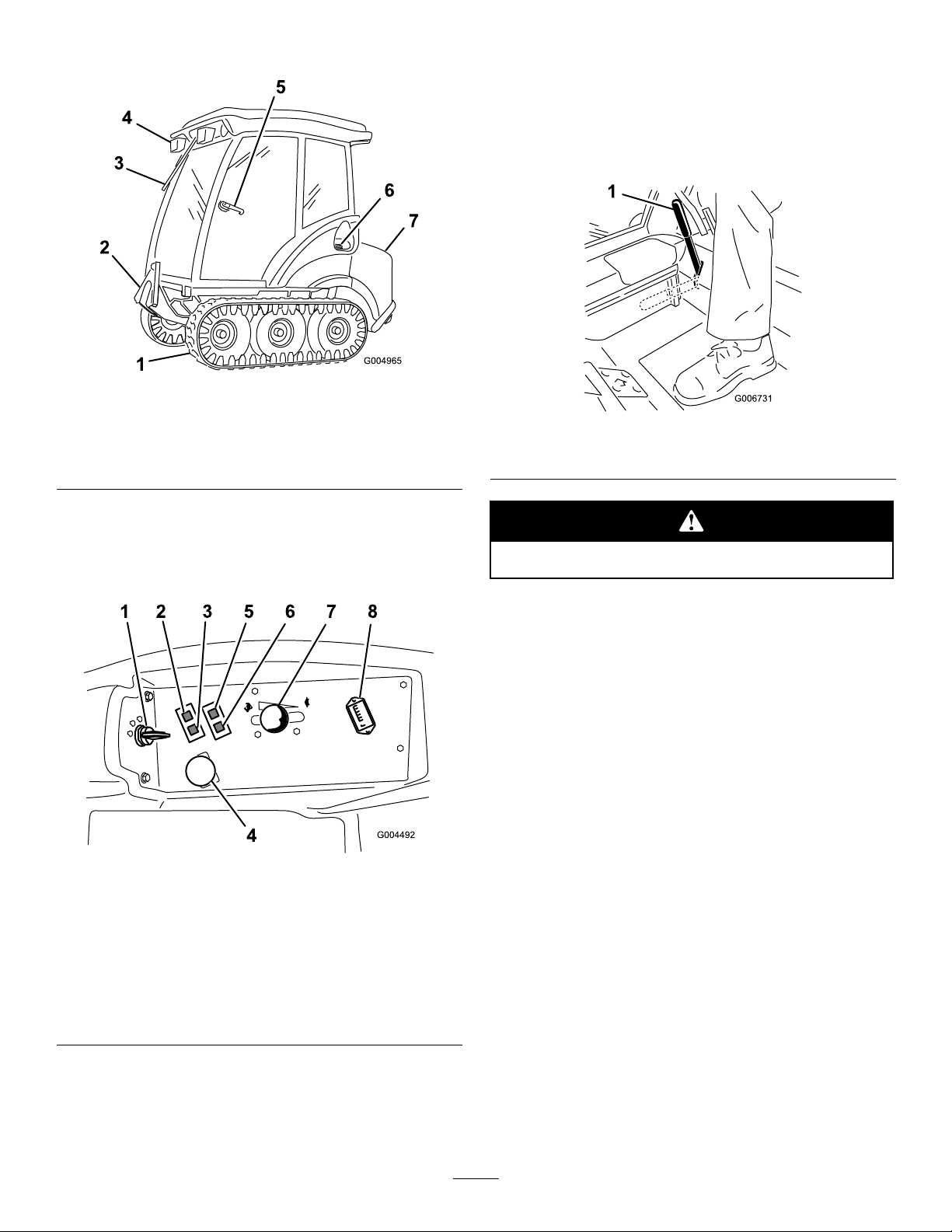
ProductOverview
Figure3
1.Track5.Doorlatch
2.Frontliftarm6.Fuelcap(bothsides)
3.Windshieldwiper7.Hood
4.Worklights
ParkingBrakeLever
Whenevertheengineisshutoff,engagetheparking
braketopreventaccidentalmovementofthemachine.
Toengagetheparkingbrake,pulltheparkingbrakelever
rearwardandup(Figure5).Toreleasetheparkingbrake,
pushtheparkingbrakeleverforwardanddown.
Figure5
1.Parkingbrakelever
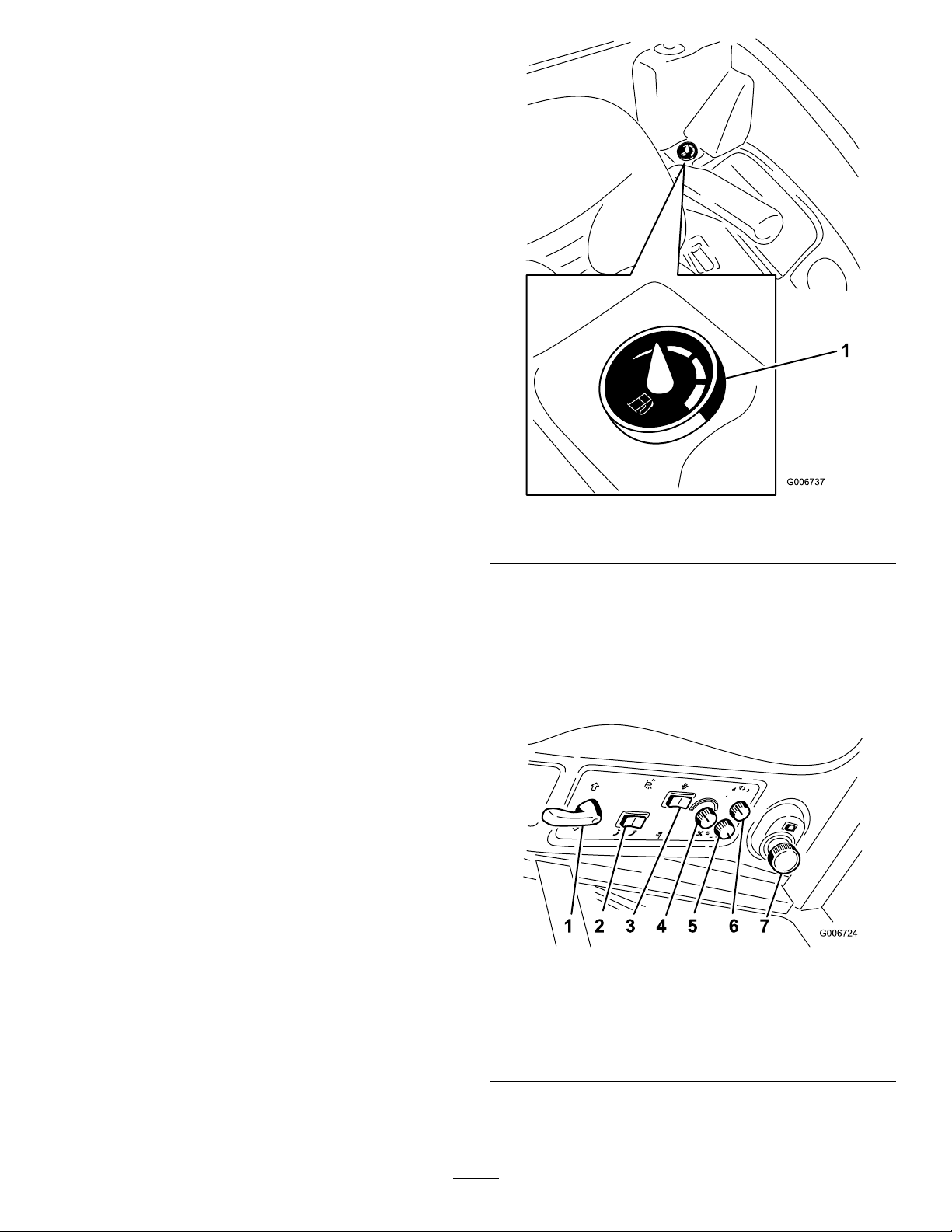
Controls
Becomefamiliarwithallthecontrolsbeforeyoustartthe
engineandoperatethemachine(Figure3andFigure4).
Figure4
TractorControlPanel
1.Ignitionswitch
2.Enginecoolant
temperaturewarning
light
3.Glowpluglight
4.Powertakeoff(PTO)
Switch
5.Oilpressurewarninglight
6.Chargeindicatorlight
7.Throttlelever
8.Hourmeter
Donotparkthemachineonaslope.
IgnitionSwitch
Theignitionswitchhasthreepositions:Off,
On/Preheat,andStart.
ThrottleLever
Thethrottlelevercontrolsthespeedoftheengine.
MovingthethrottleleverforwardtowardtheFast
positionincreasestheenginespeed.Movingitrearward
towardtheSlowpositiondecreasestheenginespeed.
Thethrottle,inconjunctionwithmotioncontrollevers,
controlsgroundspeedofthemachine.Alwaysrunthe
machinewiththethrottleintheFastpositionwhen
usingattachments.
PowerTakeOff(PTO)Switch
Thepowertakeoff(PTO)switchstartsandstops
poweredattachments.
HourMeter
MotionControlLevers
Themotioncontrolleverscontroltheforwardand
rearwardmotionsaswellastheturningofthemachine.
Thehourmeterrecordsthenumberofhourstheengine
hasoperated.Itoperateswhenthekeyswitchisinthe
Runposition.Usethesetimesforschedulingregular
maintenance.
12
Page 13
GlowPlugLight(OrangeLight)
Theglowplugindicatorlightturnsonwhentheignition
switchisturnedtotheOnposition.Itremainslitfor6
seconds.Whenthelightturnsoff,theengineisready
tobestarted.
EngineCoolantTemperatureWarning
Light
Thislightglowsandthepoweredattachmentswillstop
iftheenginecoolanttemperatureishigh.Ifthemachine
isnotstoppedandthecoolanttemperaturerisesanother
20°F,theenginewillstop.
Important:Iftheattachmentshutsdownandthe
temperaturewarninglightison,pushPTOknob
down,drivetoasafeatarea,movethethrottle
levertotheSlowposition,movethemotioncontrol
leversintotheneutrallockedposition,andengage
theparkingbrake.Allowtheenginetoidlefor
severalminuteswhileitcoolstoasafelevel.Stop
theengineandcheckthecoolingsystem;referto
CheckingtheCoolingSysteminCoolingSystem
Maintenance.
Figure6
1.Fuelgauge
ChargeIndicator
Illuminateswhenthesystemchargingcircuit
malfunctions.
OilPressureWarningLight
Theoilpressurewarninglightglowswhentheoil
pressureintheenginedropsbelowasafelevel.Iflow
oilpressureeveroccurs,stoptheengineanddetermine
thecause.Repairthedamagebeforestartingtheengine
again.
FuelGauge
Thefuelgauge(Figure6)indicatesthequantityoffuel
remaininginthefueltanks.
SignalLightSwitch
Turnthesignallightswitch(Figure7)totheleftto
activatetheleftturnsignal,orrighttoactivatetheright
turnsignal.Whennishedturning,returntheswitch
totheOffposition.
Figure7
1.Signallightswitch
2.Snowthrowerdeector
controlswitch
3.Windshieldwiperswitch
4.Temperaturecontrolknob
5.Fancontrolknob
6.Lightscontrolknob
7.Cablight
13
Page 14

SnowthrowerDeectorControlSwitch
AttachmentControlPedals
Pressthesnowthrowerdeectorcontrolswitch
(Figure7)forwardtolowerthesnowthrowerdeector,
orrearwardtoraisethedeector.
Note:Thisswitchoperatesonlywhenasnowthrower
attachmentisinstalled.
WindshieldWiperSwitch
•Presstherearsideofthewindshieldwipeswitchto
activatethewipers.
Important:Ifthewindshieldisicyorsnow
covered,scrapeitoffrstbeforeusingthe
wipers.Ifthewipersarecoverediniceand/or
arefrozentothewindshield,removetheice
beforeusingthewipers.
•Pressthefrontsideoftheswitchtomomentarily
activatethewipers.
Note:IfyouhavetheoptionalWasherKitinstalled,
thissideoftheswitchwillalsoactivateastreamof
washeruidontothewindowforaslongasyou
presstheswitch.
TemperatureControlKnob
Turnthisknobtoactivateandsetthetemperatureofthe
heater.Blueindicateslesstonoheat,andredindicates
moretofullheat.
Usetheattachmentcontrolpedals(Figure8)tocontrol
thephysicalorientationoftheattachment.Usetheleft
pedaltoraiseandlowertheattachment.Usetheright
pedaltoswingtheattachmenttotherightorleft.
Note:Therightpedalisnotusedonallattachments.
Also,onsnowthrowers,onlythechuteswingsrightand
left.
Figure8
1.Presstolowerthe
attachment
2.Presstoswingthe
attachmenttotheleft
3.Presstoraisethe
attachment
4.Presstoswingthe
attachmenttotheright
WindowLatches
FanControlKnob
Thisknobcontrolsthespeedofthefan,whichblows
airfromtheheaterthroughtheventslocatedinthe
ceilingofthecab.Theknobhas4positions:Off,Low ,
Medium,andHigh.
LightsControlKnob
Thisknobcontrolsthelightsontheoutsideofthecab.
Ithasthefollowingpositions:
•Off
•Hazardlights—thehazardlightsash.
•Hazardlights/Operatinglights—thehazardlights
ashandtheoperatinglights(headlightsandtail
lights)shine.
•Headlights—theoperatinglightsshine.
CabinLight
Presstheswitchnexttothecabinlight(Figure7)toturn
thelightonandoff.Youcanadjustthelighttoaima
differentpartsofthecab.
Openthefront,rightsidewindowandrearsidewindows
byliftinguponthewindowlatchesandpushingout
(Figure9).
14
Page 15
Figure9
FrontSideWindowShown
Operation
Note:Determinetheleftandrightsidesofthe
machinefromthenormaloperatingposition.
AddingFuel
Theenginerunsonclean,freshdieselfuelwith
aminimumoctaneratingof40.Purchasefuelin
quantitiesthatcanbeusedwithin30daystoensure
fuelfreshness.
Combinedtankcapacity:11.5USgallons(43.5l)
Usesummergradedieselfuel(No.2-D)attemperatures
above20°F(-7°C)andwintergradedieselfuel
(No.1-DorNo.1-D/2-Dblend)below20°F
(-7°C).Useofwintergradedieselfuelatlower
temperaturesprovideslowerashpointandpourpoint
characteristics,thereforeeasingstartingandlessening
chancesofchemicalseparationofthefuelduetolower
temperatures(waxappearance,whichmaypluglters).
Useofsummergradedieselfuelabove20°F(-7°C)will
contributetowardlongerlifeofthepumpcomponents.
Inanemergency ,youcanescapeusingthefrontside
window .Openthewindowasnormal,thenpullthe
latchrearwardandoffoftheretainingposttoenable
youtoswingthewindowallthewayopen.
Specications
Note:Specicationsanddesignaresubjecttochange
withoutnotice.
Length
Width
Height
Weight
Attachments/Accessories
AselectionofToroapprovedattachmentsand
accessoriesareavailableforusewiththemachineto
enhanceandexpanditscapabilities.Contactyour
AuthorizedServiceDealerorDistributororgoto
www.Toro.comforalistofallapprovedattachments
andaccessories.
91inches(231cm)
49.5inches(126cm)
78inches(198cm)
2320lb(1052kg)
Important:Donotusekeroseneorgasoline
insteadofdieselfuel.Failuretoobservethis
cautionwilldamagetheengine.
Fuelisharmfulorfatalifswallowed.Long-term
exposuretovaporscancauseseriousinjuryand
illness.
•Avoidprolongedbreathingofvapors.
•Keepfaceawayfromnozzleandgastankor
conditioneropening.
•Keepfuelawayfromeyesandskin.
15
Page 16

Incertainconditions,fuelisextremely
ammableandhighlyexplosive.Areor
explosionfromfuelcanburnyouandothers
andcandamageproperty.
•Fillthefueltankoutdoors,inanopenarea,
whentheengineiscold.Wipeupanyfuel
thatspills.
•Neverllthefueltankinsideanenclosed
trailer.
•Neversmokewhenhandlingfuel,andstay
awayfromanopenameorwherefuel
fumesmaybeignitedbyaspark.
•Storefuelinanapprovedcontainerandkeep
itoutofthereachofchildren.Neverbuy
morethana30-daysupplyoffuel.
•Donotoperatewithoutentireexhaust
systeminplaceandinproperworking
condition.
FillingtheFuelTank
1.Parkthemachineonalevelsurface.
Important:Thefueltanksareconnected,but
thefueldoesnottransferquicklyfromonetank
totheother.Itisimportantwhenllingthat
youparkonalevelsurface.Ifyouparkonahill,
youmayinadvertentlyoverllthetanks.
2.Shuttheengineoffandsettheparkingbrake.
3.Cleanaroundeachfueltankcapandremovethecap.
Important:Donotopenthefueltankswhen
parkedonahill.Thefuelcouldspillout.
4.Addfueltobothfueltanks,untiltheleveliseven
withthebottomofthellerneck(Figure10).Do
notoverllthefueltanks.
Incertainconditionsduringfueling,static
electricitycanbereleasedcausingaspark
whichcanignitethefuelvapors.Areor
explosionfromfuelcanburnyouandothers
andcandamageproperty.
•Alwaysplacefuelcontainersontheground
awayfromyourvehiclebeforelling.
•Donotllfuelcontainersinsideavehicle
oronatruckortrailerbedbecauseinterior
carpetsorplastictruckbedlinersmay
insulatethecontainerandslowthelossof
anystaticcharge.
•Whenpractical,removeequipmentfromthe
truckortrailerandrefueltheequipment
withitswheelsontheground.
•Ifthisisnotpossible,thenrefuelsuch
equipmentonatruckortrailerfroma
portablecontainer,ratherthanfromafuel
dispensernozzle.
Figure10
1.Bottomofthellerneck
5.Installthefueltankcapssecurely.Wipeupanyfuel
thatmayhavespilled.
Note:Ifpossible,llthefueltanksaftereachuse.
Thiswillminimizepossiblebuildupofcondensation
insidethefueltank.
CheckingtheEngineOilLevel
Beforeyoustarttheengineandusethemachine,check
theoillevelintheenginecrankcase;refertoChecking
OilLevelinEngineMaintenance.
CheckingtheCoolingSystem
Beforeyoustarttheengineandusethemachine,check
thecoolingsystem;refertoCheckingtheCooling
SysteminCoolingSystemMaintenance.
•Ifafueldispensernozzlemustbeused,keep
thenozzleincontactwiththerimofthefuel
tankorcontaineropeningatalltimesuntil
fuelingiscomplete.
CheckingtheHydraulic
System
Beforeyoustarttheengineandusethemachine,check
thehydraulicsystem;refertoCheckingtheHydraulic
SysteminHydraulicSystemMaintenance.
16
Page 17

ThinkSafetyFirst
Pleasereadallsafetyinstructionsandsymbolsinthe
safetysection.Knowingthisinformationcouldhelp
youorbystandersavoidinjury.
Operatingonicyorsteepslopescancause
slidingandlossofcontrol.
Atrackdroppingoveranedgecancausea
rollover,whichmayresultinseriousinjury,
death,ordrowning.
Alwaysusetheseatbelt.
Readandfollowtherolloverprotection
instructionsandwarnings.
Toavoidlossofcontrolandpossibilityof
rollover:
•Donotoperateneardrop-offsornearwater.
•Reducespeedanduseextremecautionon
slopes.
•Avoidsuddenturnsorrapidspeedchanges.
Thismachineproducessoundlevelsinexcess
of85dBAattheoperatorsearandcancause
hearinglossthroughextendedperiodsof
exposure.
Wearhearingprotectionwhenoperatingthis
machine.
Theuseofprotectiveequipmentforeyes,ears,feet,
andheadisrecommended.
OperatingtheParkingBrake
Alwayssettheparkingbrakewhenyoustopthe
machineorleaveitunattended.
SettingtheParkingBrake
1.Movethemotioncontrollevers(Figure16)outto
theneutrallockedposition.
2.Pullupandbackontheparkingbrakelevertoset
theparkingbrake(Figure12).Theparkingbrake
levershouldstayrmlyintheengagedposition.
Figure11
1.SafeZone3.Water/unsafeice
2.Usewalkbehind
equipmentneardrop-offs
andwater.
Figure12
1.Parkingbrakelever
Theparkingbrakemaynotholdthemachine
parkedonaslopeandcouldcausepersonal
injuryorpropertydamage.
Donotparkonslopesunlessthetracksare
chockedorblocked
ReleasingtheParkingBrake
Pushforwardanddownontheparkingbrakeleverto
releasetheparkingbrake(Figure12).
17
Page 18

1.Parkingbrakelever
Figure13
Figure15
1.Ignitionswitch
2.Off4.Start
3.Run/glowpug
7.Aftertheglowplugindicatorlightgoesout,turn
thekeytotheStartposition.Whentheenginestarts
releasethekey .
StartingtheEngine
1.Sitontheseatandfastentheseatbelt.
2.Ensurethatthemotioncontrolsareintheneutral
lockedposition.
3.Settheparkingbrake;refertoSettingtheParking
Brake.
4.MovethePTO(powertakeoff)switchtotheoff
position(Figure14).
Important:Usestartingcyclesofnomorethan
15secondsperminutetoavoidoverheatingthe
startermotor.
Note:Additionalstartingcyclesmayberequired
whenstartingtheengineforthersttimeafterthe
fuelsystemhasbeencompletelydrained.
8.LeavethethrottlemidwaybetweentheSlowand
Fastpositionsuntiltheengineandhydraulicsystem
warmup.
Important:Whenengineisstartedforthe
rsttime,orafteranengineoilchange,oran
overhauloftheengine,transmission,orwheel
motor,operatethemachinewiththethrottle
leverintheSlowpositioninboththeforward
andreversedirectionsforonetotwominutes.
AlsooperatetheliftleverandPTOleverto
ensureproperoperationofallparts.Thenshut
theengineoffandcheckuidlevels,checkfor
oilleaks,looseparts,andanyothernoticeable
malfunctions.
Figure14
1.Ignitionswitch
2.Throttlecontrol
3.Glowpluglight
4.Powertakeoffswitch
(PTO)
5.MovethethrottlelevermidwaybetweentheFast
andSlowpositions(Figure14).
6.TurntheignitionkeyclockwisetotheRunposition
(Figure15).
Theglowpluglightwillturnonfor6seconds.
Shuttheengineoffandwaitforallmoving
partstostopbeforecheckingforoilleaks,loose
parts,orothermalfunctions.
DrivingtheMachine
Thethrottlecontrolregulatestheenginespeedas
measuredinrpm(revolutionsperminute).Place
thethrottlecontrolintheFastpositionforbest
performance.AlwaysoperateintheFastthrottle
positionwhenrunningpoweredattachments.
18
Page 19

Themachinecanturnveryrapidly.Y oumay
losecontrolofitandcausepersonalinjuryor
damagetomachine.
•Usecautionwhenmakingturns.
•Slowthemachinedownbeforemaking
sharpturns.
1.Releasetheparkingbrake.
Note:Theenginewillkillifthetractioncontrol
leversaremovedwiththeparkingbrakeengaged.
2.Movetheleverstothecenter,un-lockedposition.
3.Drivethemachineasfollows:
•Togostraightforward,slowlypushthemotion
controlleversforward(Figure16).
•Togostraightrearward,slowlypullthemotion
controlleversrearward(Figure16).
•Toturn,slowthemachinebypullingbackon
bothleversandthenpushforwardonthelever
ontheoppositesidefromwhichyouwantto
turn(Figure16).
•Tostop,pullthemotioncontrolleverstothe
neutralposition.
Note:Thefartheryoumovethetractioncontrol
leversineitherdirection,thefasterthemachinewill
moveinthatdirection.
Figure16
1.Motioncontrol
lever-neutrallocked
position
2.Centerun-lockposition
3.Forward
4.Backward
StoppingtheMachine/Engine
1.Movethetractioncontrolleverstoneutralandto
thelockedposition.
2.DisengagethePTO,settheparkingbrake,and
movethethrottlelevertotheSlowposition.
3.Lettheengineidlefor60seconds.
4.TurntheignitionkeytotheOffposition(Figure15).
Waitforallmovingpartstostopbeforeleavingthe
operatingposition.
5.Removethekeybeforetransportingorstoring
machine.
Important:Makesuretoremovethekeyasthe
fuelpumporaccessoriesmayrunandcause
thebatterytolosecharge.
19
Page 20

3.Raisethemachineadapterontheliftarmintothe
attachmentadapter.
Childrenorbystandersmaybeinjuredifthey
moveorattempttooperatethemachinewhile
itisunattended.
Alwaysremovetheignitionkeyandsetthe
parkingbrakewhenleavingthemachine
unattended,evenifjustforafewminutes.
OperatingAttachments
ChangingtheAttachmentOrientation
Usetheattachmentcontrolpedals(Figure17)to
controlthephysicalorientationoftheattachment.Use
theleftpedaltoraiseandlowertheattachment.Usethe
rightpedaltoswingtheattachmenttotherightorleft.
Note:Therightpedalisnotusedonallattachments.
Also,onsnowthrowers,onlythechuteswingsright
andleft.
4.Securetheadapterstogetherwiththeattachment
pinandhairpincotterasshowninFigure18.
Figure18
1.Attachmentpin
2.Cotterpin
5.Iftheattachmentispoweredbyhydraulics,connect
thehydrauliccouplerontheattachmenttothoseon
thefrontliftarm.
Figure17
1.Presstolowerthe
attachment/liftarm
2.Presstoswingthe
attachmenttotheleft
3.Presstoraisethe
attachment/liftarm
4.Presstoswingthe
attachmenttotheright
Important:Donotcontinuetoholdapedalafter
theattachmenthasnishedmoving.Doingsowill
damagethehydraulicsystem.
Connecting/Disconnectingan
Attachment
ReadtheOperator’sManualsuppliedwiththeattachment
beforeoperating.
1.Lowerthefrontliftarm.
Important:Ensurethatthecouplersareclean
beforeconnectingthemtopreventhydraulic
systemcontamination.
6.IftheattachmentispoweredbythePTO,extend
theattachmentPTOshaftandinsertitontothe
machinePTOshaft(Figure19).
Figure19
1.PTOshaft
Note:Toremoveanattachment,performtheabove
stepsinreverse.
2.Drivethemachineintopositionbehindthe
attachmentadapter.
20
Page 21

EngagingthePowerTakeOff(PTO)
Thepowertakeoff(PTO)switchstartsandstops
poweredattachments.
1.Iftheengineiscold,allowtheenginetowarmup5
to10minutesbeforeengagingthePTO.
2.Whileseatedintheseat,releasethepressureonthe
tractioncontrolleversandplacetheminneutral.
3.PulluponthePTOswitchtoengageit(Figure20).
Figure20
1.PTOswitch
Thesafetyinterlocksystemalsoisdesignedtostopthe
enginewhenthetractioncontrolsaremovedfromthe
neutrallockedpositionwiththeparkingbrakeengaged.
IfyourisefromtheseatwhenthePTOisengaged
thereisa1seconddelayandthentheenginestops.
TestingtheSafetyInterlockSystem
ServiceInterval:Beforeeachuseordaily
Testthesafetyinterlocksystembeforeyouusethe
machineeachtime.Ifthesafetysystemdoesnot
operateasdescribedbelow ,haveanAuthorizedService
Dealerrepairthesafetysystemimmediately .
1.Sittingontheseat,engagetheparkingbrakeand
movethePTOtoon.Trystartingtheengine;the
engineshouldnotcrank.
2.Sittingontheseat,engagetheparkingbrakeand
movethePTOtooff.Moveeithermotioncontrol
lever(outofneutrallockedposition).Trystarting
theengine;theengineshouldnotcrank.Repeatfor
othercontrollever.
DisengagingthePTO
Todisengage,pushthePTOswitchtotheoffposition.
TheSafetyInterlockSystem
Ifthesafetyinterlockswitchesaredisconnected
ordamagedthemachinecouldoperate
unexpectedlycausingpersonalinjury.
•Donottamperwiththeinterlockswitches.
•Checktheoperationoftheinterlock
switchesdailyandreplaceanydamaged
switchesbeforeoperatingthemachine.
UnderstandingtheSafetyInterlock
System
Thesafetyinterlocksystemisdesignedtopreventthe
enginefromstartingunless:
•Youaresittingontheseatortheparkingbrakeis
engaged.
•Thepowertakeoff(PTO)isdisengaged.
•Themotioncontrolleversareintheneutrallocked
position
•Theenginetemperatureisbelowthemaximum
operatingtemperature.
3.Sittingontheseat,engagetheparkingbrake,move
thePTOswitchtooffandmovethemotioncontrol
leverstotheneutrallockedposition.Nowstartthe
engine.Whiletheengineisrunning,releasethe
parkingbrake,engagethePTOandriseslightly
fromtheseat;theengineshouldstopwithin2
seconds.
4.Withoutanoperatorontheseat,engagetheparking
brake,movethePTOswitchtooffandmovethe
motioncontrolleverstotheneutrallockedposition.
Nowstarttheengine.Whiletheengineisrunning,
centereithermotioncontrol;theengineshould
stopwithin2seconds.Repeatfortheothermotion
control.
5.Withoutanoperatorontheseat,disengagethe
parkingbrake,movethePTOswitchtooff,and
movethemotioncontrolleverstotheneutral
lockedposition.Trystartingtheengine;theengine
shouldnotcrank.
UsingtheSCMtoDiagnoseSystem
Problems
Themachineisequippedwithastandardcontrol
module(SCM)monitoringsystemthattracksthe
functionofvariouskeysystems.TheSCMislocated
undertherightcontrolpanel.Accessitthroughthe
sidepanelcover(Figure21).Toopenthesidepanel
cover,releasethe2latchesandpulloutonit.
21
Page 22

Figure21
G006855
1234
1.Sidepanelcover
2.Latches
OnthefaceoftheSCMare11LEDsthatilluminate
toindicatevarioussystemconditions.Sevenofthese
lightscanbeusedbytheoperatorforsystemdiagnosis.
RefertoFigure22foradescriptionofwhateach
lightmeans.FordetailsonusingtherestoftheSCM
functions,refertotheServiceManual,availablethrough
yourAuthorizedToroDistributor.
PositioningtheSeat
ChangingtheSeatPosition
Theseatcanmoveforwardandbackward.Positionthe
seatwhereyouhavethebestcontrolofthemachine
andaremostcomfortable.
1.Toadjust,movetheleversidewaystounlockthe
seat(Figure23).
Figure23
1.Backrestknob3.Lumbarsupport
adjustmentknob
2.Seatsuspensionknob4.Seatpositionadjustment
lever
Figure22
1.Hightemperatureshutdown—theenginetemperaturehas
exceededsafelevelsandtheenginehasbeenshutdown.
Checkthecoolingsystem.
2.Hightemperaturewarning—theenginetemperatureis
approachingunsafelevelsandthePTOhasbeenshut
down.Checkthecoolingsystem.
3.Operatorisintheseat
4.ThePTOisOn
5.Theparkingbrakeisnotengaged
6.ControlsareinNeutral
7.TheSCMisreceivingpowerandisoperational
2.Slidetheseattothedesiredpositionandrelease
levertolockinposition.
3.Verifythattheseathaslockedintoplaceby
attemptingtomoveitbackandforth.
ChangingtheSeatSuspension
Theseatcanbeadjustedtoprovideasmoothand
comfortableride.Positiontheseatwhereyouaremost
comfortable.
Withoutsittingontheseat,turntheknobinfronteither
directiontoprovidethebestcomfort(Figure23).
22
Page 23

Figure24
1.Seatsuspensionknob2.Operatorweightsetting
ChangingtheBackPosition
Thebackoftheseatcanbeadjustedtoprovidea
comfortableride.Positionthebackoftheseatwhereit
ismostcomfortable.
Toadjustit,turntheknob,undertheright-sidearm
rest,ineitherdirectiontoprovidethebestcomfort
(Figure23).
ChangingtheLumbarSupport
Thebackoftheseatcanbeadjustedtoprovidea
customizedlumbarsupportforyourlowerback.
Toadjustit,turntheknobundertheleft-sidearm
rest,ineitherdirectiontoprovidethebestcomfort
(Figure23).
UnlatchingtheSeat
Toaccessthehydraulicandothersystemsunderthe
seat,youneedtounlatchtheseatandswingitforward.
1.Usetheseatpositionadjustmentlevertoslidethe
seatallthewayforward.
2.Pushoneoftheseatlatches,locatedbehindandto
thesidesoftheseat,rearwardtounlatchtheseat
andpullforwardonthetopoftheseat(Figure25).
Figure25
1.Seatlatch
MovingaNon-functioning
Machine
Ifthemachinebreaksdown,runsoutoffuel,etc.you
mayneedtopullitwithawinchtoloaditontoatrailer..
Todoso,yourstneedtoopenthehydraulicby-pass
valves.
Important:Nevertowthemachinebecause
hydraulicdamagemayoccur.
MovingtheMachine
1.Disengagethepowertakeoff(PTO)andturn
theignitionkeytooff.Movetheleverstothe
neutrallockedpositionandapplytheparkingbrake.
Removethekey .
2.Lifttheseat.
3.Rotatebothby-passvalvescounterclockwise1turn
(Figure26).
Thisallowshydraulicuidtoby-passthepump
enablingthetrackstoturn.
Important:Donotrotatetheby-passvalves
morethan2.5turns.Thispreventsvalvesfrom
comingoutofthebodyandcausinguidto
runout.
23
Page 24

Important:Donotattempttoturntheunitwhile
ontheramp;youmaylosecontrolanddriveoffthe
side,orthetracksmaycomeoff.
Avoidsuddenaccelerationwhendrivinguparampand
suddendecelerationwhenbackingdownaramp.Both
maneuverscancausetheunittotipbackward.
Loadingaunitontoatrailerortruckincreases
thepossibilityofbackwardtip-overandcould
causeseriousinjuryordeath.
Figure26
1.Rightby-passvalve
2.Leftby-passvalve
4.Disengagetheparkingbrakebeforemovingthe
machine.
ChangingtoMachineOperation
Rotateeachby-passvalveclockwiseandhandtighten
them(torqueofapproximately71in-lb(8N⋅m))
(Figure26).
Note:Donotovertightentheby-passvalves.
Themachinewillnotdriveunlessby-passvalvesare
turnedin.
LoadingMachines
Useextremecautionwhenloadingunitsontrailersor
trucks.Onefullwidthrampthatiswideenoughto
extendbeyondtheendofthetracksisrecommended
insteadofindividualrampsforeachsideoftheunit
(Figure27).Thelowerrearsectionofthemachine
frameextendsbackbetweentherearwheelsandserves
asastopfortippingbackward.Havingafullwidthramp
providesasurfacefortheframememberstocontactif
theunitstartstotipbackward.Ifitisnotpossibleto
useonefullwidthramp,useenoughindividualramps
tosimulateafullwidthcontinuousramp.
•Useextremecautionwhenoperatingaunit
onaramp.
•Useonlyasingle,fullwidthramp;Donot
useindividualrampsforeachsideofthe
unit.
•Ifindividualrampsmustbeused,use
enoughrampstocreateanunbrokenramp
surfacewiderthantheunit.
•Donotexceeda15degreeanglebetween
rampandgroundorbetweenrampand
trailerortruck.
•Avoidsuddenaccelerationwhiledrivingunit
uparamptoavoidtippingbackward.
•Avoidsuddendecelerationwhilebacking
unitdownaramptoavoidtippingbackward.
Therampshouldbelongenoughsothattheanglesdo
notexceed15degrees(Figure27).Asteeperanglemay
causeattachmentcomponentstogetcaughtastheunit
movesfromramptotrailerortruck.Steeperangles
mayalsocausetheunittotipbackward.Ifloadingon
ornearaslope,positionthetrailerortrucksoitison
thedownsideoftheslopeandtherampextendsupthe
slope.Thiswillminimizetherampangle.Thetraileror
truckshouldbeaslevelaspossible.
Figure27
1.Trailer3.Notgreaterthan
15degrees
2.Fullwidthramp4.Fullwidthramp—sideview
24
Page 25

TransportingtheMachine
Useaheavy-dutytrailerortrucktotransportthe
machine.Ensurethatthetrailerortruckhasall
necessarylightingandmarkingasrequiredbylaw .
Pleasecarefullyreadallthesafetyinstructions.
Knowingthisinformationcouldhelpyouorbystanders
avoidinjury.
Totransportthemachine:
•Ensurethatyourvehicle,hitch,safetychains,and
trailerareadequatefortheloadyouarepullingand
thattheymeetalllocaltrafcregulationsforyour
area.
•Lockthebrakeandblockthetracks.
•Securelyfastenthemachinetothetrailerortruck
withstraps,chains,cable,orropesasrequiredby
localtrafcregulationsinyourarea(Figure28).
Figure28
1.Fronttie-downs
2.Reartie-down(leftside
shown)
25
Page 26

Maintenance
Note:Determinetheleftandrightsidesofthemachinefromthenormaloperatingposition.
Important:Engineoil,batteries,hydraulicoil,andenginecoolantarepollutantstotheenvironment.
Disposeoftheseaccordingtoyourstateandlocalregulations.
RecommendedMaintenanceSchedule(s)
MaintenanceService
Interval
Aftertherst10hours
Aftertherst50hours
Aftertherst200hours
Beforeeachuseordaily
Every50hours
Every150hours
Every200hours
Every400hours
MaintenanceProcedure
•Checkthealternatorbelttension.
•T orquethewheellugnuts.
•Changetheengineoilandlter.
•Changethehydraulicoilandlter.
•T estthesafetysystem.
•Checktheengineoillevel.
•Drainwater/contaminantsfromthewaterseparator.
•Checktheenginecoolantlevel.
•Cleantheradiatorwithcompressedair(donotusewater)
•Checkthehydraulicuidlevel.
•Greasethebearingandbushinggreasettings.(Greasemorefrequentlywhen
operatingconditionsareextremelydustyorsandy.)
•Checkbatterycableconnections.
•Checkthetirepressure.
•Changetheengineoilandlter.
•Inspectcoolingsystemhosesandseals.Replacethemifcrackedortorn.
•Checkthealternatorbelttension.
•T orquethewheellugnuts.
•Servicetheaircleaner.
•Replacethefuelltercanister.
•Replacethefuelpre-lter .
•Checkthefuellinesandconnections.
Every800hours
Every1,500hours
Every2years
Important:Refertoyour
•Changethehydraulicoilandlter.
•Inspectenginevalveclearance.RefertoyourEngineOperator’sManual.
•Replacemovinghoses
•Drainandcleanthefueltank.
•Flushandreplacecoolingsystemuid.
Engine Operator’ s Man ual
foradditionalmaintenanceprocedures.Adetailed
ServiceManualisalsoavailableforpurchasefromyourAuthorizedToroDistributor.
26
Page 27

DailyMaintenanceChecklist
Duplicatethispageforroutineuse.
Fortheweekof: MaintenanceCheckItem
Mon.Tues.Wed.Thurs.Fri.
CheckSafetyInterlock
Operation
CheckParkingBrake
Operation
CheckFuelLevel
CheckHydraulicOilLevel
CheckEngineOilLevel
CheckCoolingSystemFluid
Level
CheckDrainWater/Fuel
Separator
CheckAirFilterRestriction
Indicator
CheckRadiator&Screenfor
Debris
CheckUnusualEngine
Noises
CheckUnusualOperating
Noises
CheckHydraulicHosesfor
Damage
CheckFluidLeaks
CheckTirePressure
CheckInstrumentOperation
LubricateAllGreaseFittings
Touch-upDamagedPaint
1.Checkglowplugandinjectornozzles,ifhardstarting,excesssmokeorroughrunningisnoted.
3
1
2
Sat.Sun.
2.Immediatelyaftereverywashing,regardlessoftheintervallisted.
3.Ifindicatorshowsred
NotationforAreasofConcern
Inspectionperformedby:
ItemDate
Information
27
Page 28

Ifyouleavethekeyintheignitionswitch,someonecouldaccidentlystarttheengineandseriously
injureyouorotherbystanders.
Removethekeyfromtheignitionbeforeyoudoanymaintenance.
Figure29
ServiceIntervalChart
Lubrication
GreasingtheBearingsand
Bushings
ServiceInterval:Every50hours(Greasemore
frequentlywhenoperatingconditions
areextremelydustyorsandy .)
GreaseType:No.2GeneralPurposeLithiumBase
Grease.
Important:Lubricatethegreasettings
immediatelyaftereverywashing,regardlessof
intervalspecied.Bearinglifecanbenegatively
affectedbyimproperwashdownprocedures.Do
notwashdowntheunitwhenitisstillhotandavoid
directinghigh-pressureorhighvolumesprayatthe
bearingsorseals.
1.Wipethegreasettingscleansoforeignmatter
cannotbeforcedintothebearingorbushing.
2.Pumpgreaseintothettings.
3.Wipeoffexcessgrease.
Thegreasettinglocationsandquantitiesareasfollows:
•Bogiepivotassembly—2(Figure30)
Figure30
1.Bogiepivotassembly(2)
•PTOshaftbearings—2(Figure31)
•2PTOshaftuniversaljoints—2perjoint(Figure31,
rearjointshown)
28
Page 29

•Hydrauliccylinderpivotpins—2(Figure31)
G004971
G004501
123456
7
•Liftarmpivot—1(Figure31)
Figure31
EngineMaintenance
AirCleanerMaintenance
•Checktheaircleanerbodyfordamagewhichcould
possiblycauseanairleak.Replaceadamagedair
cleanerbody.Checkthewholecleanairintake
systemforleaks,damage,orloosehoseclamps.
•Servicetheaircleanerlterwhentheaircleaner
indicator(Figure32)showsredorevery400
hours(morefrequentlyinextremelydustyordirty
conditions).Donotoverservicetheairlter.
Figure32
1.Aircleanerlatch5.Aircleanerbody
2.Aircleanercover6.Aircleanerindicator
3.Gasket
4.Filter
7.Rubberoutletvalve
•Besurethecoverisseatedcorrectlyandsealswith
theaircleanerbody.
ServicingtheAirCleaner
ServiceInterval:Every400hours
1.Pullthelatchoutwardandrotatetheaircleaner
covercounter-clockwise(Figure32).
2.Removethecoverfromtheaircleanerbody
(Figure32).
3.Beforeremovingthelter,uselowpressure
air(40psi,cleananddry)tohelpremovelarge
accumulationsofdebrispackedbetweenoutsideof
primarylterandthecanister.
Thiscleaningprocesspreventsdebrisfrommigrating
intotheintakewhentheprimarylterisremoved.
29
Page 30

Important:Avoidusinghighpressureairwhich
couldforcedirtthroughthelterintotheintake
tract.
4.Removeandreplacetheprimarylter(Figure32).
Important:Donotcleantheusedelementto
avoiddamagetotheltermedia.
5.Inspectthenewlterforshippingdamage,checking
thesealingendofthelterandthebody .
Important:Donotuseadamagedelement.
6.Ensurethatthefoamgasketisinplaceinthecover
andthatitisnottornordamaged(Figure32).If
itisdamaged,replaceit.
7.Insertthenewlterbyapplyingpressuretotheouter
rimoftheelementtoseatitinthecanister.
Important:Donotapplypressuretotheexible
centerofthelter.
8.Cleanthedirtejectionportlocatedintheremovable
cover,asfollows:
A.Removetherubberoutletvalvefromthecover
(Figure32).
1.Parkthemachineonalevelsurface,lowerthe
attachment,movethethrottlelevertotheSlow
position,stoptheengine,andremovethekeyfrom
theignitionswitch.Openthehood.
2.Removethedipstick(Figure33),wipeitclean,and
installthedipstick.Removethedipstickandcheck
theoillevel.
TheoillevelshouldbeuptotheFullmarkonthe
dipstick.
B.Cleanthecavity .
C.Replacetheoutletvalve.
9.Installthecoverorientingtherubberoutletvalvein
adownwardposition—betweenapproximately5:00
to7:00whenviewedfromtheend.
10.Resettheindicator(Figure32)ifshowingred.
ServicingtheEngineOil
CheckingtheEngineOilLevel
ServiceInterval:Beforeeachuseordaily
Theengineisshippedwithoilinthecrankcase;however,
theoillevelmustbecheckedbeforeandafterthe
engineisrststarted.Checkoillevelbeforeeachday’s
operationoreachtimemachineisused.
Thecrankcasecapacityisapproximately4qt.(3.8l)
withthelter.Usehigh-qualityengineoilthatmeets
thefollowingspecications:
•APIClassicationLevelRequired:CH-4,CI-4or
higher.
•Preferredoil:SAE15W-40(above0°F(-17°C)
•Alternateoil:SAE10W -30or5W-30(all
temperatures)
Note:ToroPremiumEngineoilisavailablefromyour
distributorineither15W -40or10W-30viscosity.Seethe
partscatalogforpartnumbers.
Figure33
1.Dipstick
2.Oilll
3.IftheoillevelisbelowtheFullmark,removethell
cap(Figure33)andaddoiluntilthelevelreachesthe
Fullmarkonthedipstick.
Important:Donotoverll.
Note:Useacleanfunneltopreventspills.
4.Installtheoilllcapandclosethehood.
ChangingtheEngineOilAndFilter
ServiceInterval:Aftertherst50hours
Every150hours
Changetheoilandlterinitiallyafterrst50hours
ofoperationandthenevery150hoursofoperation
thereafter.Ifpossible,runtheenginejustbefore
changingtheoilbecausewarmoilowsbetterand
carriesmorecontaminantsthancoldoil.
1.Positionthemachineonalevelsurface.
2.Openthehood.
3.Setadrainpanundertheoilpanandinlinewith
thedrainplug(Figure34).
30
Page 31

FuelSystem
Maintenance
Note:RefertoAddingFuelforproperfuel
recommendations.
Undercertainconditions,dieselfuelandfuel
vaporsarehighlyammableandexplosive.A
reorexplosionfromfuelcanburnyouand
othersandcancausepropertydamage.
Figure34
1.Oillter
4.Cleantheareaaroundthedrainplug.
5.Removethedrainplugandallowtheoiltoowinto
drainpan.
6.Removeandreplacetheoillter(Figure34).
7.Aftertheoilisdrained,installthedrainplugand
wipeupanyoilthatisspilled.
8.Fillthecrankcasewithoil;refertoCheckingthe
EngineOilLevel.
2.Drainplug
•Useafunnelandllthefueltankoutdoors,
inanopenarea,whentheengineisoffand
iscold.Wipeupanyfuelthatspills.
•Donotllthefueltankcompletelyfull.Add
fueltothefueltankuntilthelevelistothe
bottomofthellerneck.
•Neversmokewhenhandlingfuel,andstay
awayfromanopenameorwherefuel
fumesmaybeignitedbyaspark.
•Storefuelinaclean,safety-approved
containerandkeepthecapinplace.
ServicingtheWaterSeparator
ServiceInterval:Beforeeachuseordaily—Drain
water/contaminantsfromthewater
separator.
Every400hours—Replacethefuel
ltercanister.
1.Placeacleancontainerunderthefuellter.
2.Loosenthedrainplugonthebottomofthelter
canister.
31
Page 32

Figure35
1.Waterseparator2.Drainplug
3.Cleantheareawheretheltercanistermounts.
4.Removetheltercanisterandcleanthemounting
surface.
5.Lubricatethegasketontheltercanisterwithclean
oil.
6.Installtheltercanisterbyhanduntilthegasket
contactsmountingsurface,thenrotateitan
additional1/2turn.
7.Tightenthedrainplugonthebottomofthelter
canister.
Figure36
1.Hoseclamps
2.Loosenthehoseclampsatbothendsofthelter
andpullthefuellinesoffofthelter.
3.Slidethehoseclampsontoendsofthefuellines.
4.Pushfuellinesontothepre-lterandsecurethem
withhoseclamps.
Important:Ensurethatthearrowonthesideof
thelterpointstowardtheinjectionpump.
2.Fuelprelter
CleaningtheFuelTank
ServiceInterval:Every2years
Note:Also,drainandcleanthetankifthefuelsystem
becomescontaminatedorifthemachineistobestored
foranextendedperiod.
Usecleandieselfueltoushoutthetank.
ReplacingtheFuelPre-Filter
ServiceInterval:Every400hours/Yearly(whichever
comesrst)
Thefuelpre-lter(Figure36)islocatedbetweenthefuel
tankandfuelpump.
1.Clampbothfuellinesthatconnecttothepre-lter
sofuelcannotdrainwhenthelinesareremoved
(Figure36).
FuelLinesandConnections
ServiceInterval:Every400hours/Yearly(whichever
comesrst)
Inspectthefuellinesfordeterioration,damage,chafng,
orlooseconnections.
BleedingtheFuelSystem
1.Parkthemachineonalevelsurface.Ensurethatthe
fueltankisatleasthalffull.
2.Unlatchandraisethehood.
3.Placearagundertheairbleedscrewonthefuel
injectionpumpandopenit(Figure37).
32
Page 33

1.Fuelinjectionpumpbleedscrew
Figure37
Figure38
1.PipeconnectionfromtheinjectionpumptotheNo.1injector
nozzle
4.TurnthekeyintheignitionswitchtotheRun
position.
Theelectricfuelpumpwillbeginoperation,thereby
forcingairoutaroundtheairbleedscrew .
Theenginemaystartduringthisprocedure.
Movingfansandbeltsinarunningenginecan
severelyinjureyouorbystanders.
Keephands,ngers,looseclothing/jewelry,
andhairawayfromtheenginefanandbelt
duringthisprocedure.
5.LeavethekeyintheOnpositionuntilasolidstream
offuelowsoutaroundthescrew .
6.TightenthescrewandturnkeytotheOffposition.
Note:Normally,theengineshouldstartafterabove
bleedingproceduresarefollowed.However,if
enginedoesnotstart,airmaybetrappedbetween
injectionpumpandinjectors;refertoBleedingAir
FromtheInjectors.
2.MovethethrottletotheFastposition.
3.TurntheignitionkeytheStartpositionandwatch
thefuelowaroundtheconnector.
Theenginemaystartduringthisprocedure.
Movingfansandbeltsinarunningenginecan
severelyinjureyouorbystanders.
Keephands,ngers,looseclothing/jewelry,
andhairawayfromtheenginefanandbelt
duringthisprocedure.
4.Tightenthepipeconnectorsecurelywhenitattains
asolidow .
5.TurnthekeytotheOffposition.
6.Repeatthisprocedurefortheremainingnozzles.
BleedingAirFromtheInjectors
Note:Thisprocedureshouldbeusedonlyifthefuel
systemhasbeenpurgedofairthroughnormalpriming
proceduresandenginewillnotstart;refertoBleeding
theFuelSystem.
1.Placearagunderthepipeconnectioncomingfrom
theinjectionpumptotheNo.1injectornozzleas
illustratedinFigure38.
33
Page 34

ElectricalSystem
Maintenance
Important:Wheneverworkingwiththeelectrical
system,alwaysdisconnectthebatterycables,
negative(-)cablerst,topreventpossiblewiring
damagefromshort-outs.
ServicingtheBattery
ServiceInterval:Every50hours—Checkbatterycable
connections.
Warning
CALIFORNIA
Proposition65Warning
Batteryposts,terminals,andrelated
accessoriescontainleadandleadcompounds,
chemicalsknowntotheStateofCalifornia
tocausecancerandreproductiveharm.
Washhandsafterhandling.
Keepthetopofthebatteryclean.Ifyoustorethe
machineinalocationwheretemperaturesareextremely
high,thebatterywillrundownmorerapidlythanif
themachineisstoredinalocationwheretemperatures
arecool.
Batteryterminalsormetaltoolscouldshort
againstmetalmachinecomponentscausing
sparks.Sparkscancausethebatterygassesto
explode,resultinginpersonalinjury.
•Whenremovingorinstallingthebattery,do
notallowthebatteryterminalstotouchany
metalpartsofthemachine.
•Donotallowmetaltoolstoshortbetween
thebatteryterminalsandmetalpartsofthe
machine.
Incorrectbatterycableroutingcoulddamage
themachineandcablescausingsparks.Sparks
cancausethebatterygassestoexplode,
resultinginpersonalinjury.
•Alwaysdisconnectthenegative(black)
batterycablebeforedisconnectingthe
positive(red)cable.
•Alwaysconnectthepositive(red)battery
cablebeforeconnectingthenegative(black)
cable.
Keepthetopofthebatterycleanbywashingit
periodicallywithabrushdippedinammoniaor
bicarbonateofsodasolution.Flushthetopsurfacewith
wateraftercleaningit.Donotremovethellcapswhile
cleaningthebattery.
Thebatterycablesmustbetightontheterminalsto
providegoodelectricalcontact.
Ifcorrosionoccursattheterminals,disconnectthe
cables,negative(-)cablerst,andscrapetheclampsand
terminalsseparately.Reconnectthecables,positive(+)
cablerst,andcoattheterminalswithpetroleumjelly.
StoringtheBattery
Ifthemachinewillbestoredmorethan30days,remove
thebatteryandchargeitfully.Eitherstoreitonashelf
oronthemachine.Leavethecablesdisconnectedifit
isstoredonthemachine.Storethebatteryinacool
atmospheretoavoidquickdeteriorationofthechargein
thebattery.T opreventthebatteryfromfreezing,make
sureitisfullycharged.Thespecicgravityofafully
chargedbatteryis1.265-1.299.
CheckingtheFuses
Themachinefusesarelocatedunderthecontrolpanel.
Accessthemthroughthesidepanelcover(Figure39).
Toopenthesidepanelcover,releasethe2latchesand
pulloutonit.
34
Page 35

Figure39
1.Sidepanelcover
2.Latches
Thecabfusesarelocatedinfrontofthecabcontrol
panel(Figure40).Accessthembyremovingthenger
boltssecuringthefuseaccesscover.
otherwiseyoucoulddamagetheelectricalsystem.
Refertothedecalnexttothemachinefuses(Figure41)
foradiagramofeachfuseanditsamperage(thecab
fusesareall20Afusesandareusedtoprotecttheheater,
windshieldwipers,lights,fan,andothercabfunctions).
Note:Ifafuseblowsfrequently,youprobablyhavea
shortintheelectricalsystemandshouldhaveitserviced
byaqualiedservicetechnician.
Figure41
Figure40
1.Thumbscrews
2.Fuseaccesscover
3.Cabfuses
Ifthemachinestopsorhasotherelectricalsystemissues,
checkthefuses.Graspeachfuseinturnandremove
themoneatatime,checkingtoseeifanyareblown.If
youneedtoreplaceafuse,alwaysusethesametype
andamperageratedfuseastheoneyouarereplacing,
35
Page 36

DriveSystem
G001055
CoolingSystem
Maintenance
CheckingtheTirePressure
ServiceInterval:Every50hours
Maintaintheairpressureinthetiresat35psi(241kPa)
(Figure42).Uneventirepressurecancausethetracksto
slip.Ifthetracksslip,evenlyincreasethetirepressure
ineachtireby10psi(69kPa)untilthetracksnolonger
slipwhendriving.Donotexceed50psi(345kPa)in
eachtire.
Maintenance
Dischargeofhotpressurizedcoolantor
touchinghotradiatorandsurroundingparts
cancausesevereburns.
•Donotremovetheradiatorcapwhenthe
engineishot.Alwaysallowtheengineto
coolatleast15minutesoruntiltheradiator
capiscoolenoughtotouchwithoutburning
yourhandbeforeremovingtheradiatorcap.
•Donottouchradiatorandsurroundingparts
thatarehot.
Therotatingfananddrivebeltcancause
personalinjury.
•Donotoperatethemachinewithoutthe
coversinplace.
Figure42
Note:Checkthetireswhentheyarecoldtogetthe
mostaccuratepressurereading.
•Keepngers,handsandclothingclearof
rotatingfananddrivebelt.
•Shutofftheengineandremovetheignition
keybeforeperformingmaintenance.
Swallowingenginecoolantcancausepoisoning.
•Donotswallowenginecoolant.
•Keepoutofreachfromchildrenandpets.
CheckingtheCoolingSystem
ServiceInterval:Beforeeachuseordaily—Checkthe
enginecoolantlevel.
Thecoolingsystemislledwitha50/50solutionof
waterandpermanentethyleneglycolantifreeze.Check
thelevelofthecoolantintheexpansiontankatthe
beginningofeachdaybeforestartingtheengine.The
capacityofthecoolingsystemis6quarts(7.5l).
36
Page 37

1.Checkthelevelofthecoolantintheexpansiontank
(Figure43).Thecoolantlevelshouldbebetweenthe
marksonthesideofthetank.
Figure43
1.Expansiontank
2.Ifcoolantlevelislow ,removetheexpansiontank
capandreplenishthesystem.Donotoverll.
BrakeMaintenance
AdjustingtheParkingBrake
InterlockSwitch
1.Stopthemachine,movethecontrolleversfullyinto
theneutral-lockedposition,settheparkingbrake,
andremovetheignitionkey .
2.Removetheboltssecuringthefrontpaneland
removethepanel(Figure44).
3.Installtheexpansiontankcap.
CleaningtheRadiator
ServiceInterval:Beforeeachuseordaily—Cleanthe
radiatorwithcompressedair(donot
usewater)
Topreventtheenginefromoverheating,theradiator
mustbekeptclean.Normally,checktheradiatordaily
and,ifnecessary,cleananydebrisofftheseparts.
However,itwillbenecessarytocheckandclean
theradiatorfrequentlyinextremelydustyanddirty
conditions.
Note:IfthePTOorengineshutsoffdueto
overheating,rstchecktheradiatorforexcessivebuildup
ofdebris,ice,orsnow .
Cleantheradiatorasfollows:
1.Openthehood.
2.Workingfromthefansideoftheradiator,blowout
debriswithlowpressure(50psi)compressedair(do
notusewater).Repeatthestepfromthefrontof
theradiatorandagainfromthefanside.
3.Aftertheradiatoristhoroughlycleaned,cleanout
debristhatmayhavecollectedinthechannelatthe
radiatorbase.
Figure44
1.Frontpanelbolts
3.Loosenthe2screwssecuringtheinterlockswitch.
Figure45
1.Tabonthebrakeshaft3.Screws
2.Parkingbrakeinterlock
switch
4.0.015to0.045inch(0.4to
1mm)
4.Closethehood.
37
Page 38

4.Movetheswitchtowardthetabonthebrakeshaft
untilthedistancebetweenthetabandswitchbodyis
0.015to0.045inch(0.4to1mm)(Figure45).
5.Securetheswitch.
6.Testtheadjustmentasfollows:
BeltMaintenance
CheckingtheAlternatorBelt
Tension
A.Ensurethattheparkingbrakeisengagedandyou
arenotsittingontheseat,thenstarttheengine.
B.Movethecontrolleversoutoftheneutrallocked
position.
Theengineshouldstop.Ifnot,recheckthe
adjustmentyoumadetotheswitch.
7.Installthefrontpanel.
ServiceInterval:Aftertherst10hours
Every200hours
1.Apply10lbofforcetothealternatorbelt,midway
betweenthepulleys.
2.Ifthedeectionisnot3/8in.(10mm),loosenthe
alternatormountingbolts(Figure46).
Figure46
1.Mountingbolt2.Alternator
3.Increaseordecreasethealternatorbelttensionand
tightenthebolts.
4.Checkthedeectionofthebeltagaintoensurethat
thetensioniscorrect.
38
Page 39

ControlsSystem
Maintenance
4.Holdingthecontrolleveragainsttheframe,move
theswitchtowardtheleveruntilthedistance
betweenleverandswitchbodyis0.015to0.045inch
(0.4to1mm)(Figure48).
AdjustingtheControlLever
NeutralInterlockSwitch
1.Stopthemachine,movethecontrolleversfullyinto
theneutral-lockedposition,settheparkingbrake,
andremovetheignitionkey .
2.Removetheboltssecuringthefrontpaneland
removethepanel(Figure47).
Figure47
1.Frontpanelbolts
5.Securetheswitch.
6.Repeatsteps3to5fortheotherlever.
7.Installthefrontpanel.
AdjustingtheControlLever
NeutralReturn
Ifthemotioncontrolleversdonotalignwiththeneutral
slotswhenreleasedfromthereversedriveposition,
adjustmentisrequired.Adjusteachlever,spring,and
rodseparately.
1.DisengagethePTO,movethemotioncontrollevers
totheneutrallockedpositionandsettheparking
brake.
2.MovethethrottlelevertotheSlowposition,stopthe
engine,removethekey,andwaitforallmovingparts
tostopbeforeleavingtheoperatingposition.
3.Removetheboltssecuringthefrontpaneland
removethepanel(Figure49).
3.Loosenthe2screwssecuringtheinterlockswitch
(Figure48).
Figure48
1.Controllever3.Screws
2.Neutralinterlockswitch
4.0.015to0.045inch(0.4to
1mm)
Figure49
1.Frontpanelbolts
4.Moveoneoftheleverstotheneutralpositionbut
notlocked(Figure51).
5.Pulltheleverbackuntiltheclevispin(onanarm
abovethepivotshaft)contactstheendofthe
slot(justbeginningtoputpressureonthespring)
(Figure50).
39
Page 40

1.Clevispin
2.Slot
3.Jamnuts
Figure50
AdjustingtheTractionDrive
forNeutral
Thisadjustmentmustbemadewithtracksturning.
Mechanicalorhydraulicjacksmayfailto
supportmachineandcauseaseriousinjury.
•Usejackstandswhensupportingmachine.
•Donotusehydraulicjacks.
4.Adjustmentbolt
5.Yoke
6.Checkwherethecontrolleverisrelativetonotchin
console(Figure51).Itshouldbecenteredallowing
levertopivotoutwardtotheneutrallockposition.
Figure51
1.Neutralposition2.Neutrallockedposition
7.Ifadjustmentisneeded,loosenthenutandjamnut
againsttheyoke(Figure50).
8.Applyingslightrearwardpressureonthemotion
controllever,turntheheadoftheadjustmentbolt
intheappropriatedirectionuntilthecontrolleveris
centeredintheneutrallockposition(Figure50).
Theenginemustberunningtoperformthis
adjustment.Contactwithmovingpartsorhot
surfacesmaycausepersonalinjury.
Keephands,feet,face,clothing,andotherbody
partsawayfromrotatingparts,mufer,and
otherhotsurfaces.
1.Raisetheframeontostablejackstandssothatthe
trackscanrotatefreely .
2.Slideseatforward,unlatchit,andswingitupand
forward.
3.Disconnecttheelectricalconnectorfromtheseat
safetyswitch.Temporarilyinstallajumperwire
acrossterminalsinthewiringharnessconnector.
4.Starttheengine,ensurethatthethrottleleveris
midwaybetweentheFastandSlowpositions,and
releasetheparkingbrake
Note:Themotioncontrolleversmustbein
theneutrallockedpositionwhilemakingany
adjustments.
5.Adjustthepumprodlengthononesidebyrotating
thehexshaft,intheappropriatedirection,untilthe
correspondingwheelisstillorslightlycreepingin
reverse(Figure52).
Note:Keepingrearwardpressureontheleverwill
keepthepinattheendoftheslotandallowthe
adjustmentbolttomovethelevertotheappropriate
position.
9.Tightenthenutandjamnut(Figure50).
10.Repeatsteps4through9fortheothercontrollever.
11.Installthefrontpanel.
40
Page 41

Figure52
1.Rightpumprod5.JamNut
2.Leftpumprod6.Hexshaft
3.Balljoint7.Balljoint
4.Bolt
Electricalsystemwillnotperformpropersafety
shutoffwithjumperwireinstalled.
•Removejumperwirefromwireharness
connectorandplugconnectorintoseat
switchwhenadjustmentiscompleted.
•Neveroperatethisunitwithjumperinstalled
andseatswitchbypassed.
12.Lowertheseatintoposition.
13.Removethejackstands.
AdjustingtheMaximum
GroundSpeed
Note:Ifyouwishtoreducethemaximummachine
speed,setthespeedforbothcontrolleversasdirected
below,thenbackeachstopboltoutanequalamount
towardthecontrolleveruntilyoureachthemaximum
speedyoudesire(youwilllikelyhavetotestyour
adjustmentseveraltimes).Ensurethatthemachine
drivesstraightanddoesnotturnwhenbothcontrol
leversarepushedallthewayforward.Ifthemachine
turns,youdonothavethestopboltsevenlysetandwill
needtoadjustthemfurther.
6.Movethemotioncontrolleverforwardandreverse,
thenbacktoneutral.Thewheelmuststopturning
orslightlycreepinreverse.
7.MovethethrottlelevertotheFastposition.Make
surewheelremainsstoppedorslightlycreepsin
reverse,adjustifnecessary.
8.Repeatsteps5through7fortheotherside.
9.Tightenthejamnutsattheballjoints(Figure50).
10.MovethethrottlelevertotheSlowpositionandstop
theengine.
11.Removethejumperwirefromthewireharness
connectorandplugtheconnectorintotheseat
switch.
1.DisengagethePTO,movethemotioncontrollevers
totheneutrallockedpositionandsettheparking
brake.
2.MovethethrottlelevertotheSlowposition,stopthe
engine,removethekey,andwaitforallmovingparts
tostopbeforeleavingtheoperatingposition.
3.Removetheboltssecuringthefrontpaneland
removethepanel(Figure53).
Figure53
1.Frontpanelbolts
41
Page 42

4.Loosenthejamnutonthestopboltforoneofthe
controllevers(Figure54).
1.Controllever
2.Controlleverpost
Figure55
3.Bolts
Figure54
1.Stopbolt
2.Controllever4.0.060inch(1.5mm)
3.Jamnut
5.Threadthestopboltallthewayin(awayfromthe
controllever).
6.Pushthecontrolleverallthewayforwarduntilit
stopsandholditthere.
7.Threadthestopboltout(towardsthecontrollever)
untilthereisagapof0.060inch(1.5mm)between
theheadofthestopboltandthecontrollever.
8.Tightenthejamnuttosecurethestopboltinplace.
9.Repeatsteps4through8fortheothercontrollever.
10.Installthefrontpanel.
AdjustingtheTracking
1.DisengagethePTO,movethemotioncontrollevers
totheneutrallockedpositionandsettheparking
brake.
4.Havesomeonepushthecontrolleverposts(notthe
controllevers)allthewayforwardintothemaximum
speedpositionandholdthemthere.
5.Adjustthecontrolleverssothattheylineup
Figure56)andtightenthebolts,securingthelevers
(
totheposts.
2.MovethethrottlelevertotheSlowposition,stopthe
engine,removethekey,andwaitforallmovingparts
tostopbeforeleavingtheoperatingposition.
3.Loosentheboltssecuringthecontrollevers
(Figure55)
Figure56
42
Page 43

HydraulicSystem
Maintenance
Thereservoirislledatthefactorywith
approximately5quarts(4.7l)ofhighqualitytractor
transmission/hydraulicuid.Therecommended
replacementuidisasfollows:
ToroPremiumTransmission/HydraulicTractorFluid
(Availablein5gallonpailsor55gallondrums.Seeparts
catalogorT orodistributorforpartnumbers.)
Alternateuids:IftheTorouidisnotavailable,
Mobil®424hydraulicuidmaybeused.
Note:T orowillnotassumeresponsibilityfordamage
causedbyimpropersubstitutions.
Note:Manyhydraulicuidsarealmostcolorless,
makingitdifculttospotleaks.Areddyeadditivefor
thehydraulicsystemoilisavailablein2/3oz.(20ml)
bottles.Onebottleissufcientfor4-6gal(15-221)of
hydraulicoil.Orderpartnumber44-2500fromyour
authorizedTorodistributor.
CheckingtheHydraulicFluid
Level
ServiceInterval:Beforeeachuseordaily
1.Positionthemachineonalevelsurface.Placethe
controlsintheneutrallockedpositionandstartthe
engine.RunengineatlowestpossibleRPMtopurge
thesystemofair.DonotengagethePTO.Raise
thedecktoextendliftcylinders,stoptheengine,and
removethekey.
2.Raisetheseattoaccessthehydraulicuidtank.
3.Removethehydraulicllcap(Figure57)fromller
neck.
Figure57
1.Dipstick2.Fillcap
4.Removethedipstickandwipeitwithacleanrag
(Figure57).
5.Placethedipstickintothellerneck;thenremoveit
andchecklevelofuid(Figure57).
Iflevelisnotwithinnotchedareaofthedipstick,
addenoughhighqualityhydraulicuidtoraiselevel
towithinthenotchedarea.Donotoverll.
6.Replacethedipstickandthreadthellcap
nger-tightontollerneck.
7.Checkallhosesandttingsforleaks.
ChangingtheHydraulicOil
AndFilter
ServiceInterval:Aftertherst200hours
Every800hours
1.DisengagethePTO,movethemotioncontrollevers
totheneutrallockedpositionandsettheparking
brake.
2.MovethethrottlelevertotheSlowposition,stopthe
engine,removethekey,andwaitforallmovingparts
tostopbeforeleavingtheoperatingposition.
3.Placealargepanunderthehydraulicreservoirand
transmissioncaseandremovetheplugs,drainingall
ofthehydraulicuid(Figure58).
43
Page 44

Figure58
1.Hydraulicreservoirdrain
plug
2.Filter
3.Transmissioncasedrain
plug
4.Cleantheareaaroundthehydraulicoillterand
removeit(Figure58).
5.Immediatelyinstallanewhydraulicoillter.
CabMaintenance
RefertotheROPSHardCabOperator’sManualfor
additionalcabmaintenanceprocedures.
6.Installthehydraulicreservoirandtransmissioncase
drainplugs.
7.Fillthereservoirtotheproperlevel;referto
CheckingtheHydraulicFluid.
8.Starttheengineandcheckforoilleaks.Allowthe
enginetorunforaboutveminutes,thenshutitoff.
9.Aftertwominutes,checkthelevelofthehydraulic
uid;refertoCheckingtheHydraulicFluid.
44
Page 45

Storage
Machine
1.Thoroughlycleanthemachine,deckandtheengine,
payingspecialattentiontotheseareas:
•Radiatorandradiatorscreen
•Underneaththedeck
•Underthedeckbeltcovers
•Counterbalancesprings
•PTOshaftassembly
•Allgreasettingsandpivotpoints
•Removethecontrolpanelandcleanoutinside
ofthecontrolbox
•Beneaththeseatplateandtopofthetransmission
2.Checkandadjustthetirepressure;refertoChecking
TirePressure.
3.Checkallfastenersforloosenessandtightenthem
asnecessary.
5.Drainthefuelfromthefueltank,fuellines,pump,
lter,andseparator.Flushthefueltankwithclean
dieselfuelandconnectallfuellines.
6.Thoroughlycleanandservicetheaircleaner
assembly.
7.Sealtheaircleanerinletandtheexhaustoutletwith
weatherproofmaskingtape.
8.Checktheoilllercapandfueltankcaptoensure
theyaresecurelyinplace.
4.Greaseoroilallgreasettings,pivotpoints,and
transmissionby-passvalvepins.Wipeoffanyexcess
lubricant.
5.Lightlysandandusetouchuppaintonpaintedareas
thatarescratched,chippedorrusted.Repairany
dentsinthemetalbody .
6.Servicethebatteryandcablesasfollows:
A.Removethebatteryterminalsfromthebattery
posts.
B.Cleanthebattery,terminals,andpostswitha
wirebrushandbakingsodasolution.
C.Coatthecableterminalsandbatterypostswith
Grafo112Xskin-overgrease(ToroPartNo.
505-47)orpetroleumjellytopreventcorrosion.
D.Slowlyrechargethebatteryfor24hoursevery60
daystopreventleadsulfationofthebattery.
Engine
1.Draintheengineoilfromtheoilpanandreplace
thedrainplug.
2.Removeanddiscardtheoillter.Installanewlter.
3.Relltheenginewith4quarts(3.8l)ofrecommended
motoroil.RefertoChangingtheEngineOil.
4.Starttheengineandrunitatidlespeedfortwo
minutes.
45
Page 46

Schematics
ElectricalSchematic(Rev.A)
46
Page 47

G006857
HydraulicSchematic(Rev.A)
47
Page 48

The Toro General Commercial Products Warranty
A Two-Year Limited Warranty
Conditions and Products Covered
The Toro Company and its affiliate, Toro Warranty Company,
pursuant to an a g r eement between them, jointly warrant your Toro
Commercial Product (“Product”) to be free from defects in
materials or workmanship for two years or 1500 operational
hours*, whichever occurs first. Where a warrantable condition
exists, we will repair the Product at no cost to you including
diagnosis, labor, parts, and transportation. This warranty begins
on the date the Product is delivered to the original retail purchaser.
* Product equipped with hour meter
Instructions for Obtaining Warranty Service
You are responsible for notifying the Commercial Products
Distributor or Authorized Commercial Products Dealer from whom
you purchased the Product as soon as you believe a warrantable
condition exists.
If you need help locating a Commercial Products Distributor or
Authorized Dealer, or if you have questions regarding your
warranty rights or responsibilities, you may contact us at:
Toro Commercial Products Service Department
Toro Warranty Company
8111 Lyndale Avenue South
Bloomington, MN 55420-1196
952-888-8801 or 800-982-2740
E-mail: commercial.service@toro.com
Owner Responsibilities
As the Product owner, you are responsible for required maintenance and adjustments stated in your operator’s manual. Failure
to perform required maintenance and adjustments can be grounds
for disallowing a warranty claim.
Items and Conditions Not Covered
Not all product failures or malfunctions that occur during the
warranty period are defects in materials or workmanship. This
express warranty does not cover the following:
• Product failures which result from the use of non-Toro
replacement parts, or from installation and use of add-on,
modified, or unapproved accessories
• Product failures which result from failure to perform required
maintenance and/or adjustments
• Product failures which result from operating the Product in an
abusive, negligent or reckless manner
• Parts subject to consumption through use unless found to be
defective. Examples of parts which are consumed, or used up,
during normal Product operation include, but are not limited to,
blades, reels, bedknives, tines, spark plugs, castor wheels,
tires, filters, belts, and certain sprayer components such as
diaphragms, nozzles, and check valves, etc.
• Failures caused by outside influence. Items considered to be
outside influence include, but are not limited to, weather,
storage practices, contamination, use of unapproved coolants,
lubricants, additives, or chemicals, etc.
• Normal “wear and tear” items. Normal “wear and tear” includes,
but is not limited to, damage to seats due to wear or abrasion,
worn painted surfaces, scratched decals or windows, etc.
Parts
Parts scheduled for replacement as required maintenance are
warranted for the period of time up to the scheduled replacement
time for that part.
Parts replaced under this warranty become the property of Toro.
T oro will make the final decision whether to repair any existing part
or assembly or replace it. Toro may use factory remanufactured
parts rather than new parts for some warranty repairs.
General Conditions
Repair by an Authorized Toro Distributor or Dealer is your sole
remedy under this warranty.
Neither The Toro Company nor Toro Warranty Company is
liable for indirect, incidental or consequential damages in
connection with t h e use of the Toro Products covered by this
warranty, including any cost or expense of providing substitute equipment or service during reasonable periods of
malfunction or non-use pending completion of repairs under
this warranty. Except for the Emissions warranty referenced
below, if applicable, there is no other express warranty. All
implied warranties of merchantability and fitness for use are
limited to the duration of this express warranty.
Some states do not allow exclusions of incidental or consequential
damages, or limitations on how long an implied warranty lasts, so
the above exclusions and limitations may not apply to you.
This warranty gives you specific legal rights, and you may also
have other rights which vary from state to state.
Note regarding engine warranty: The Emissions Control System
on your Product may be covered by a separate warranty meeting
requirements established by the U.S. Environmental Protection
Agency (EPA) and/or the California Air Resources Board (CARB).
The hour limitations set forth above do not apply to the Emissions
Control System Warranty. Refer to the Engine Emission Control
Warranty Statement printed in your operator’s manual or contained in the engine manufacturer’s documentation for details.
Countries Other than the United States or Canada
Customers who have purchased Toro products exported from the United States or Canada should contact their Toro Distributor (Dealer)
to obtain guarantee policies for your country, province, or state. If for any reason you are dissatisfied with your Distributor’s service or
have difficulty obtaining guarantee information, contact the Toro importer. If all other remedies fail, you may contact us at Toro Warranty
Company.
Part No. 374-0031 Rev. C
 Loading...