

Page 1

Form No. 3326–334
72 Side Discharge Deck
Groundsmaster 3000 Traction Units
30373—210000001 and Up
Operator ’s Manual
English (EN)
Page 2

Contents
Introduction
Introduction 2. . . . . . . . . . . . . . . . . . . . . . . . . . . . . . . .
Safety 3. . . . . . . . . . . . . . . . . . . . . . . . . . . . . . . . . . . . .
Before Operating 3. . . . . . . . . . . . . . . . . . . . . . . . .
While Operating 3. . . . . . . . . . . . . . . . . . . . . . . . . .
Maintenance 4. . . . . . . . . . . . . . . . . . . . . . . . . . . . .
Safety and Instruction Decals 5. . . . . . . . . . . . . . .
Specifications 6. . . . . . . . . . . . . . . . . . . . . . . . . . . . . . .
Assembly 6. . . . . . . . . . . . . . . . . . . . . . . . . . . . . . . . . .
Loose Parts 6. . . . . . . . . . . . . . . . . . . . . . . . . . . . . .
Connect Drive Shaft to Cutting Unit 7. . . . . . . . . .
Install Cutting Unit To Traction Unit 7. . . . . . . . .
Connect Drive Shaft To Traction Unit 7. . . . . . . . .
Mount Height-of-Cut Chains 8. . . . . . . . . . . . . . . .
Adjust Transport Latch 8. . . . . . . . . . . . . . . . . . . .
Grease Cutting Unit 8. . . . . . . . . . . . . . . . . . . . . . .
Before Operating 8. . . . . . . . . . . . . . . . . . . . . . . . . . . .
Check Lubricant In Gear Box 8. . . . . . . . . . . . . . .
Adjusting Height-of-Cut 9. . . . . . . . . . . . . . . . . . .
Adjusting Rollers and Gage Wheels 9. . . . . . . . . .
Adjusting Deck Pitch 10. . . . . . . . . . . . . . . . . . . . . .
Operation 11. . . . . . . . . . . . . . . . . . . . . . . . . . . . . . . . . .
Grass Deflector 11. . . . . . . . . . . . . . . . . . . . . . . . . .
Operating Tips 11. . . . . . . . . . . . . . . . . . . . . . . . . . .
Lubrication 12. . . . . . . . . . . . . . . . . . . . . . . . . . . . . . . . .
Grease Bearings, Bushings And Gear Box 12. . . . .
Maintenance 13. . . . . . . . . . . . . . . . . . . . . . . . . . . . . . . .
Disconnect Cutting Unit From Traction Unit 13. . .
Connect Cutting Unit To Traction Unit 13. . . . . . . .
Changing Gear Box Lubricant 14. . . . . . . . . . . . . . .
Replacing Grass Deflector 15. . . . . . . . . . . . . . . . . .
Adjusting Idler Pulley 15. . . . . . . . . . . . . . . . . . . . .
Replacing Drive Belt 15. . . . . . . . . . . . . . . . . . . . . .
Servicing Front Bushings In Castor Forks 16. . . . . .
Servicing Castor Wheels And Bearings 17. . . . . . .
Removing Cutter Blade 17. . . . . . . . . . . . . . . . . . . .
Inspecting And Sharpening Blade 18. . . . . . . . . . . .
Correcting Cutting Unit Mismatch 18. . . . . . . . . . .
Lift Arm Adjustment 19. . . . . . . . . . . . . . . . . . . . . .
The Toro General Commercial Products Warranty 20. .
Page
Read this manual carefully to learn how to operate and
maintain your product properly. The information in this
manual can help you and others avoid injury and product
damage. Although Toro designs and produces safe
products, you are responsible for operating the product
properly and safely.
Whenever you need service, genuine Toro parts, or
additional information, contact an Authorized Service
Dealer or Toro Customer Service and have the model and
serial numbers of your product ready. The two numbers
are stamped into a plate on front channel of the mower
deck, under cover.
Write the product model and serial numbers in the space
below:
Model No.
Serial No.
This manual identifies potential hazards and has special
safety messages that help you and others avoid personal
injury and even death. Danger, Warning, and Caution are
signal words used to identify the level of hazard.
However, regardless of the hazard, be extremely careful.
Danger signals an extreme hazard that will cause serious
injury or death if you do not follow the recommended
precautions.
Warning signals a hazard that may cause serious injury or
death if you do not follow the recommended precautions.
Caution signals a hazard that may cause minor or
moderate injury if you do not follow the recommended
precautions.
This manual uses two other words to highlight
information. Important calls attention to special
mechanical information and Note: emphasizes general
information worthy of special attention.
2000 by The Toro Company
8111 Lyndale Avenue South
Bloomington, MN 55420-1196
All Rights Reserved
Printed in the USA
2
Page 3

Safety
Hazard control and accident prevention are dependent
upon the awareness, concern, and proper training of
the personnel involved in the operation, transport,
maintenance, and storage of the machine. Improper
use or maintenance of the machine can result in injury
or death. To reduce the potential for injury or death,
comply with the following safety instructions.
Before Operating
1. Read and understand the contents of this Operator ’s
Manual before operating the machine. Become
familiar with all controls and know how to stop
quickly. A free replacement manual is available by
sending complete Model and Serial Number to:
The Toro Company
8111 Lyndale Avenue South
Minneapolis, Minnesota 55420–1196
2. Never allow children to operate the machine. Do not
allow adults to operate machine without proper
instruction. Only trained operators who have read this
manual should operate this machine.
3. Never operate the machine when under the influence
of drugs or alcohol.
4. Remove all debris or other objects that might be
picked up and thrown by the cutter blades. Keep all
bystanders away from the mowing area.
5. Keep all shields and safety devices in place. If a
shield, safety device or decal is illegible or damaged,
repair or replace it before operation is commenced.
Also tighten any loose nuts, bolts and screws to ensure
machine is in safe operating condition.
6. Do not operate machine while wearing sandals, tennis
shoes, sneakers or shorts. Also, do not wear loose
fitting clothing which could get caught in moving
parts. Always wear long pants and substantial shoes.
Wearing safety glasses, safety shoes and a helmet is
advisable and required by some local ordinances and
insurance regulations.
7. Check interlock switches daily for proper operation
(Refer To Section in Traction Unit Operator ’s Manual
on Checking Interlock Switches). Do not rely entirely
on safety switches -shut off engine before getting off
seat. If a switch fails, replace it before operating the
machine. The interlock system is for your protection,
so do not bypass it. Replace all interlock switches
every two years. Interlock switches should be adjusted
so:
A. Engine cannot be started unless traction pedal is
released (neutral position) and PTO switch is
DISENGAGED (off position).
B. Engine stops if operator gets off seat when traction
pedal is depressed.
C. Engine stops if operator gets off seat when PTO
lever is ENGAGED (on position).
8. Fill fuel tank before starting the engine. Avoid spilling
any fuel. Since fuel is flammable, handle it carefully.
A. Use an approved fuel container.
B. Do not fill tank while engine is hot or running.
C. Do not smoke while handling gasoline.
D. Fill fuel tank outdoors and up to about one inch
from top of the tank, not the filler neck.
E. Wipe up any spilled gasoline.
While Operating
9. Do not run the engine in a confined area without
adequate ventilation. Exhaust fumes are hazardous and
could possibly be deadly.
10.Maximum seating capacity is one person. Never carry
passengers.
11. Sit on the seat when starting the engine and operating
the machine.
12.This product may exceed noise levels of 85 dB(A) at
the operator position. Ear protectors are recommended
for prolonged exposure to reduce the potential of
permanent hearing damage.
13.Before starting the engine:
A. Engage the parking brake.
B. Ensure traction pedal is in neutral and PTO is in
the OFF, disengaged position.
C. After engine is started, release parking brake and
keep foot off traction pedal. Machine must not
move. If movement is evident, the neutral return
mechanism is adjusted incorrectly; therefore, shut
engine off and adjust until machine does not move
when traction pedal is released.
14.Using the machine demands attention, and to prevent
loss of control:
A. Mow only in daylight or when there is good
artificial light.
B. Drive slowly and watch for holes or other hidden
hazards.
C. Do not drive close to a sand trap, ditch, creek or
other hazard.
3
Page 4

D. Reduce speed when making sharp turns and when
turning on hillsides.
E. Avoid sudden starts and stops.
F. Before backing up, look to the rear and ensure no
one is behind the machine.
G. Watch out for traffic when near or crossing roads.
Always yield the right-of -way.
15.If engine stalls or machine loses headway and cannot
make it to the top of a slope, do not turn machine
around. Always back slowly straight down the slope.
16.DON’T TAKE AN INJURY RISK! When a person
or pet appears unexpectedly in or near the mowing
area, STOP MOWING. Careless operation, combined
with terrain angles, ricochets, or improperly positioned
guards can lead to thrown object injuries. Do not
resume mowing until area is cleared.
17.Never raise the cutting unit while the blades are
rotating.
18.If the cutting blades strike a solid object or the
machine vibrates abnormally, disengage PTO, move
throttle to SLOW, set parking brake and shut engine
off. Remove key from switch to prevent possibility of
accidental starting. Check cutting unit and traction unit
for damage and malfunctioning parts. Repair any
damage before restarting the engine and operating the
cutting unit. Be sure blades are in good condition and
blade bolts are tight.
19.Cut grass slopes carefully. Do not start, stop, or turn
suddenly.
20.Do not touch engine or muffler while engine is running
or soon after it is stopped. These areas couId be hot
enough to cause a burn.
21.Before getting off the seat:
24.Perform only those maintenance instructions described
in this manual. If major repairs are ever needed or
assistance is desired, contact an Authorized Toro
Distributor.
25.To reduce potential fire hazard, keep the engine free of
excessive grease, grass, leaves and accumulations of
dirt. Never wash a warm engine or any electrical parts
with water.
26.Be sure machine is in safe operating condition by
keeping nuts, bolts and screws tight. Check the blade
mounting bolts and nuts frequently to be sure they are
tightened to specification.
27.Make sure all hydraulic line connectors are tight, and
all hydraulic hoses and lines are in good condition
before applying pressure to the system.
28.Keep body and hands away from pin hole leaks in
hydraulic lines that eject high pressure hydraulic fluid.
Use cardboard or paper to find hydraulic leaks.
Hydraulic fluid escaping under pressure can penetrate
skin and cause injury. Fluid accidentally injected into
the skin must be surgically removed within a few
hours by a doctor familiar with this form of injury or
gangrene may result.
29.Before disconnecting or performing any work on the
hydraulic system, all pressure in system must be
relieved by stopping engine and lowering cutting unit
to the ground.
30.If the engine must be running to perform a
maintenance adjustment, keep hands, feet, clothing
and other parts of the body away from the cutting unit
blades and other moving parts.
31.Do not overspeed the engine by changing governor
settings. To be sure of safety and accuracy, have an
Authorized TORO Distributor check maximum engine
speed with a tachometer.
A. Move traction pedal to neutral position and remove
foot from pedal.
B. Set the parking brake and disengage the PTO.
C. Shut the engine off and remove the key from the
ignition switch. Wait for all movement to stop
before getting off the seat.
22.Lower the cutting unit to the ground and remove key
from ignition switch whenever machine is left
unattended.
Maintenance
23.Remove key from ignition switch to prevent accidental
starting of the engine when servicing, adjusting or
storing the machine.
32.Engine must be shut off before checking oil or adding
oil to the crankcase.
33.At the time of manufacture the cutting unit conformed
to safety standards in effect for riding mowers.
Therefore, to ensure optimum performance and safety,
always purchase genuine TORO replacement parts and
accessories to keep the Toro all TORO. NEVER USE
“WILL–FIT” REPLACEMENT PARTS AND
ACCESSORIES MADE BY OTHER
MANUFACTURERS. Look for the TORO logo to
ensure genuineness. Using unapproved replacement
parts and accessories could void the warranty of The
Toro Company.
4
Page 5
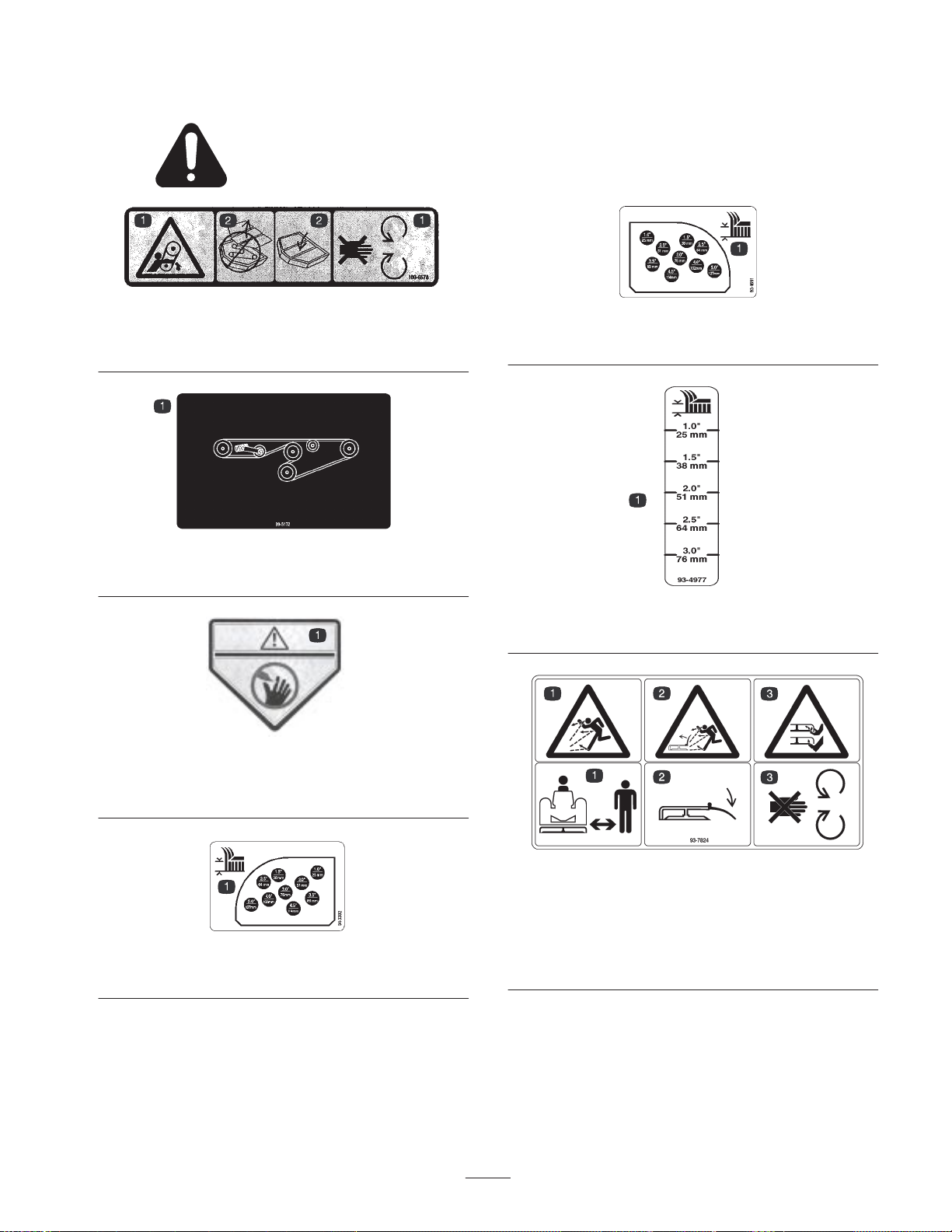
Safety and Instruction Decals
Safety decals and instructions are easily visible to the operator and are located near any
area of potential danger. Replace any decal that is damaged or lost.
Part No. 100–6578
1. Stay away from moving
parts
Part No. 99–5172
1. Belt Routing
Part No. 100–6582
1. Danger–Rotating blades
can cut hands and feet
2. Do not operate with
covers removed
Part No. 93–4691
1. Height–of–cut range, r e a r
Part No. 93–4977
1. Height-of-cut range, anti-scalp roller
Part No. 94–3392
1. Height–of–cut range, rear
1. Thrown object
hazard—keep bystanders
away.
2. Thrown object
hazard—keep deflector in
place.
5
Part No. 93–7824
3. Rotating blades can cut
hands and feet—stay
away from moving parts.
Page 6
Specifications
Type: 71-5/8 in. (1.82 m) width of cut, 3 blades.
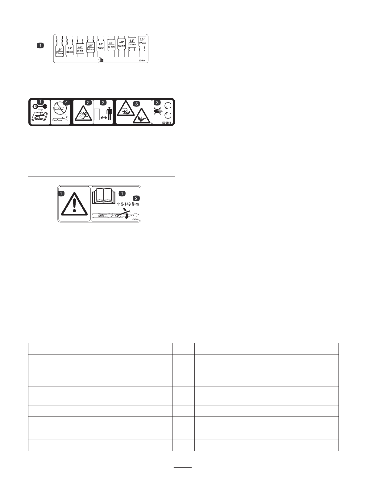
Part No. 93–4690
1. Height-of-cut range, front
Part No. 100–6553
1. Remove key and read
Operator’s Manual before
performing maintenance
2. Thrown objects–Keep
bystanders away
Part No. 93–7818
1. Danger– Read and understand Operator’s Manual for
information on blade torque.
3. Rotating blades can cut
hands and feet
4. Keep deflector in place
Height Of Cut: 1 to 4-1/2 in. (25 to 114 mm) adjustable
in 1/2 in. (13 mm) increments. Front adjustment is with
snapper pin and grooves in castor shaft. Rear adjustment
is with hanger brackets and pin.
Construction: Housing is 12 gauge steel.
Cutter Drive: PTO driven gear box transmits power
through a “BB” section hex. belt to all blade spindles.
Blades: Three 24.75 in. (55 mm) long, .25 in. thick,
heat-treated steel.
Suspension & Castor Wheels: Two front castors,
consisting of 10 in. (254 mm) pneumatic wheel and tire
assembly with sealed ball bearings. Rear of deck is
suspended from lift arms with adjustable deck rake.
Hydraulic counter balance and lift system designed
integral with deck for maximum flotation.
Anti–scalp Features: Anti-scalp cup located on each
blade. Skid on left end of deck. Two adjustable gage
wheels on front of deck. Four adjustable gage wheels on
rear of deck.
Deck Covers: 14 gauge steel covers.
Quick Attach System: Tapered joint with over center
adjustable tensioning latch.
Weight: Approximately 500 lb.
Specifications and design subject to change without
notice.
Assembly
Note: Determine the left and right sides of the machine from the normal operating position.
Loose Parts
Note: Use this chart as a checklist to ensure that all parts have been received. Without these parts, total setup cannot be
completed.
Description Qty. Use
Drive Shaft
Capscrew
Locknut
Roll Pin
Decals 2
Parts Catalog 1
Operator’s Manual 1 Read before operating machine.
CE Certificate 1
1
2
2
1
Mount drive shaft to cutting unit.
Apply over decal, part no. 100–6582, for ANSI
complicance (2 places).
Registration Card 1 Fill out and return to Toro.
6
Page 7

Connect Drive Shaft to Cutting
Unit
1. Remove (2) selftapping screws securing drive shaft
guard to mounting plate (Fig. 1). Retain fasteners for
re–installation.
1
3
2
2
Figure 1
1. Drive shaft guard
2. Gearbox
2. Slide male drive shaft into female PTO shaft. Align
mounting hole in gear case input shaft with hole in
drive shaft yoke and slide together.
3. Secure yoke to shaft with roll pin.
4. Secure yoke to shaft with (2) capscrews and nuts.
5. Re–install drive shaft shaft guard to mounting plate
with (2) selftapping screws previously removed.
3. Drive shaft
3
1
Install Cutting Unit To Traction
Unit
1. Loosen the ball joint jam nuts on the cutting unit.
Figure 2
1. Latch cover
2. Release lever
3. Tighten the ball joint jam nuts.
4. Tighten the release lever with a 3/4 in. wrench.
5. Install the latch cover to the lift arm with the clevis pin
and hairpin cotter previously removed.
6. Close the needle valve and lower the seat.
3. Shaft latch
Connect Drive Shaft To
Traction Unit
Important The drive shaft yokes must be exactly in
line.
1. Rotate drive shaft until splines line up. To rotate drive
shaft, insert screw driver into universal joint.
2. Slide coupler onto tractor PTO shaft until it clicks
(Fig. 3).
2. Secure the lift arm assemblies to the traction unit as
follows (Fig. 2):
A. With engine off, raise seat and open needle valve.
This allows lift arms to float freely.
B. Remove hairpin cotter and clevis pin securing latch
cover to lift arm.
C. Pivot release lever upward.
D. Slide cutting unit lift arms onto traction unit lift
arms, inserting shaft latch into slot in traction unit
lift arms.
E. Pivot release lever downward and hand tighten by
rotating clockwise.
1
1
Figure 3
1. Drive shaft coupler
7
Page 8

Mount Height-of-Cut Chains
1. Remove hairpin cotter and clevis pin from
height-of-cut chains (Fig. 4).
1
Figure 4
1. Height-of-cut chain
5. Rotate front of deck upward and insert latch rod into
front hole (service position) in latch plate.
6. Loosen latch plate flange head capscrews and adjust
latch plate position if required.
7. Tighten flange head capscrews securing latch plate to
gearbox.
8. Remove hairpin cotters and clevis pins securing
height-of-cut chains to rear of deck.
9. Remove latch rod from rear hole in latch plate.
Grease Cutting Unit
Before the cutting unit is operated, it must be greased to
ensure proper lubricating characteristics: refer to
Lubrication section of manual. Failure to properly grease
the cutting unit will result in premature failure of critical
parts.
2. Start tractor and raise deck to highest possible position
and turn off engine.
3. Align height-of-cut chain with hole for desired
height-of-cut, install clevis pin and secure with hairpin
cotter.
Adjust Transport Latch
1. Start tractor and raise deck to highest possible position
and turn off engine.
2. Loosen (2) flange head capscrews securing latch plate
to side of gearbox (Fig. 5).
2
1
Before Operating
Check Lubricant In Gear Box
The gear box is designed to operate with SAE 80–90 EP.
gear lube. Although the gear box is shipped with lubricant
from the factory, check the level before operating the
cutting unit.
1. Position the machine and cutting unit on a level
surface.
2. Remove check plug from side of gear box and make
sure lubricant is up to bottom of hole (Fig. 6). If level
of lubricant is low, remove fill plug on end of gear
case and add enough lubricant to bring it up to bottom
of hole in side.
1
3
2
Figure 5
1. Latch plate 2. Latch rod
3. Rotate latch rod downward from front of traction unit.
4. Insert latch rod into rear hole (transport position) in
latch plate.
1. Filler plug
2. Check plug
8
Figure 6
3. Drain plug
Page 9

Adjusting Height-of-Cut
The height–of–cut is adjustable from 1 to 5 inches in 1/2
inch increments.
1. Start engine and raise cutting unit. Stop engine after
cutting unit is raised.
2. Remove front snapper pins from castor arms and slide
castor wheel assembly up or down (Fig. 8).
3. Insert snapper pin into castor arm and through groove
in castor shaft to get desired height-of-cut (Fig. 7).
5. Mount height-of-cut chains to corresponding
height-of-cut hole with clevis pin and hairpin cotter
(Fig. 10).
Figure 10
6. When using 1 inch height-of-cut, move skids and gage
wheels to the highest holes.
Figure 7
1
Figure 8
1. Snapper p i n
4. Remove hairpin cotter and clevis pin securing
height-of-cut chains to rear of deck (Fig. 9).
1
Adjusting Rollers and Gage
Wheels
Note: If cutting unit is to be used in the 1 or 1-1/2 in.
height-of-cut setting, cutting unit rollers must be
positioned in the top bracket holes.
Adjusting the Front Roller
1. Remove the bolt and nut securing the roller shaft to the
cutting unit bracket (Fig. 11).
2. Slide the shaft out of the lower bracket holes, align the
roller with the top holes, and install the shaft.
3. Secure the roller shaft to the cutting unit bracket with
the bolt and nut.
1
2
1. Height of cut chain
Figure 9
Figure 11
1. External roller 2. Roller shaft
Adjusting the Rear (Internal) Rollers
1. Remove the cotter pin securing the roller shafts to the
brackets on the underside of the deck (Fig. 12).
9
Page 10

2. Slide the shafts out of the lower bracket holes, align
the rollers with the top holes, and install the shafts.
3. Install the cotter pins to secure the assemblies.
2
1
2
Figure 12
1. Internal rollers 2. Roller shaft
Adjusting the Front Gage Wheel
Note: If cutting unit is to be used in the 1 in. height-of-cut
setting, cutting unit gage wheels must be positioned in the
highest position.
1. Remove the bolt and nut securing the gage wheel to
the cutting unit brackets.
1
3
1
Figure 14
1. Gage wheel
2. Gage wheel support
3. Locking hub
Adjusting Deck Pitch
Deck pitch is the difference in height-of-cut from the front
of the blade plane to the back of the blade plane. Toro
recommends a blade pitch of .25 inches. That is the back
of the blade plane is .25 inches higher than the front.
1. Position machine on a level surface on shop floor.
2. Set deck to the desired height-of-cut.
3. Rotate (1) blade so it points straight forward.
4. Using a short ruler, measure from floor to front tip of
blade. Then, measure from floor to rear tip of blade.
5. Subtract the front dimension from rear dimension to
calculate your pitch.
6. To adjust pitch, start tractor and raise deck to highest
possible position and turn off engine.
Figure 13
1. Gage wheel
2. Align roller, tube and spacer with top holes in brackets
and secure with bolt and nut.
Adjusting the Rear Gage Wheel
Note: If cutting unit is to be used in the 1 in. height-of-cut
setting, cutting unit gage wheels must be positioned in the
highest position.
1. Adjust gage wheels by loosening locking hub,
positioning gage wheel support at desired height and
re-tightening locking hub. Make sure gage wheel
support pins are positioned in holes in deck.
7. Loosen jam nuts on top or bottom of height-of-cut
chain U-bolt (Fig. 15).
2
1
3
Figure 15
1. Height-of-cut chain
2. U-bolt
3. Rear height of cut pin
8. Adjust other set of nuts to raise or lower rear of deck
and attain correct deck pitch.
9. Tighten jam nuts.
10.Lower deck.
Note: If desired deck pitch cannot be attained, relocate
rear height of cut pins (Fig. 15) to a lower or higher
setting.
10
Page 11

Operation
Note: Determine the left and right sides of the machine
from the normal operating position.
Grass Deflector
Operating Tips
For best results, the following tips are recommended:
• Mow When Grass Is Dry—Mow either in the late
morning to avoid the dew, which causes grass
clumping or in late afternoon to avoid the damage that
can be caused by direct sunlight on the sensitive,
freshly mowed grass.
Warning
The grass deflector (Fig. 16) is a safety device that
diverts grass and other foreign objects being
discharged downward. The blades could throw
debris a considerable distance with sufficient
force to cause personal injury or damage to
property.
• Make sure the deflector is in the normal
operating position whenever the cutting unit is
engaged.
• Never operate the cutting unit with the
deflector removed from the cutting unit or it
tied/blocked in a raised position.
• If the grass deflector is damaged, repair or
replace the affected part(s).
Note: The deflector is spring loaded into its downward
normal operating position, but the operator can
temporarily swing it out of the way to facilitate loading in
a trailer or when otherwise necessary.
• Mow At Proper Intervals—Under most normal
conditions you’ll need to mow approximately every
4–5 days. But remember, grass grows at different rates
at different times. This means that in order to maintain
the same height-of-cut, which is a good practice,
you’ll need to cut more frequently in early spring; as
the grass growth rate slows in mid summer, cut only
every 8–10 days. If you are unable to mow for an
extended period due to weather conditions or other
reasons, mow first with the height-of-cut at a high
level; then mow again 2–3 days later with a lower
height setting.
• Always Mow With Sharp Blades—A sharp blade
cuts cleanly and without tearing or shredding the grass
blades like a dull blade. Tearing and shredding causes
the grass to turn brown at the edges which impairs
growth and increases susceptibility to diseases.
Caution
This machine produces sound levels in excess of
85dBA at the operators ear and can cause hearing
loss through extended periods of exposure.
Wear hearing protection when operating this
machine.
2
Figure 16
1. Grass deflector 2. Springs
• Transporting—Use transport latch when transporting
over long distances or rough terrain.
• Trailering—loading or unloading machine from a
trailer, remove rear height-of-cut hanger pins, to allow
1
11
maximum deck rotation.
• After Operating—To ensure optimum performance,
clean underside of mower housing after each use. If
residue is allowed to build up in mower housing
cutting performance will decrease.
• Deck Pitch—Toro recommends a blade pitch of .25
inches. A pitch larger than .25 inches will result in less
power required, larger clippings and a poorer quality
of cut. A pitch less than .25 inches will result in more
power required, smaller clippings and a better quality
of cut.
Page 12

Lubrication
Grease Bearings, Bushings
And Gear Box
The cutting unit must be lubricated regularly. If machine
is operated under normal conditions, lubricate castor
bearings and bushings with No. 2 general purpose lithium
base grease or molybdenum base grease, after every 8
hours of operation or daily, whichever comes first.
Lubricate fittings immediately after every washing,
regardless of the interval listed.
1. The cutting unit has bearings and bushings that must
be lubricated, and these lubrication points are: front
castor shaft bushings (2) (Fig. 17), blade spindle
bearings (3) (Fig. 18), gage wheel (Fig. 19), right and
left push arm ball joints (Fig. 20).
Figure 19
Figure 20
Figure 17
Figure 18
2. Position the machine and cutting unit on a level
surface and lower cutting unit. Remove check plug
from side of gear box and make sure lubricant is up to
bottom of hole. If level of lubricant is low, remove fill
plug on top of gear case and add SAE 80–90 EP gear
lube until level is up to bottom of hole in side.
1
3
2
Figure 21
1. Fill plug
2. Check plug
3. Drain plug
12
Page 13

Maintenance
5. Remove hairpin cotter and clevis pin securing latch
cover to lift arm (Fig. 24).
Note: Determine the left and right sides of the machine
from the normal operating position.
Disconnect Cutting Unit From
Traction Unit
Note: Implements are heavy and may require two people
to handle.
1. Start tractor and raise deck to highest possible position
and turn off engine.
2. Remove hairpin cotter and clevis pin securing
height-of-cut chains to rear height-of-cut brackets
(Fig. 22).
1
6. Loosen release lever by rotating it counterclockwise.
7. Pivot release lever upward and remove shaft latch
from slot in traction unit lift arm.
1
3
2
Figure 24
1. Latch cover
2. Release lever
3. Shaft latch
8. Pull rearward on lock collar to release drive shaft
coupler from tractor.
5
4
4. Traction unit lift arm
5. Machined surface
Figure 22
1. Height-of-cut chain
3. Rotate ignition key to run position and move lift lever
forward to lower cutting unit.
4. Raise seat and open needle valve (Fig. 23). This allows
lift arms to float freely.
1
Figure 23
1. Needle valve
9. Stay clear of lift arms and move deck away from
tractor allowing lift arms to fall.
10.Secure hairpin cotter and clevis pin to height-of-cut
chains for storage.
11. Close needle valve.
Connect Cutting Unit To
Traction Unit
1. Center traction unit in front of cutting unit on any flat
hard surface.
2. Raise seat and open needle valve (Fig. 23). This allows
lift arms to float freely.
3. Adjust lift arms heights making sure that the
machined surface on top of each traction unit lift arm
is parallel to ground (Fig. 24). (Raise or lower lift arm
casting by pushing up or down from behind the front
tires or using wrench in front of tractor)
4. Check for dirt and debris on mating parts and clean as
required.
5. Turn castor wheels so they point straight forward.
6. Secure first lift arm assembly to traction unit as
follows:
13
Page 14

A. Remove hairpin cotter and clevis pin securing latch
cover to lift arm (Fig. 24).
B. Pivot release lever upward (Fig. 24).
C. Slide cutting unit lift arm onto traction unit lift
arm, inserting shaft latch into slot in traction unit
lift arm (Fig. 24).
Note: If latch does not fall into slot in traction unit lift
arm, raise or lower lift arm casting by pushing up or down
from behind the front tires.
D. Pivot release lever downward and tighten securely
by rotating clockwise (Fig. 24).
7. Install other lift arm on tractor by rotating deck
towards tractor, aligning lift arm to tractor arm and
repeating step 5. If latch does not fall into slot in
traction unit lift arm the arms are not lined up.
A. If lift arms on traction unit are not at the correct
height for deck arms to slide on, push up or down
on lift arm castings from behind the front tires until
deck arm lines up and slides on.
B. If lift arms on deck do not line up side to side.
Rotate castor wheels side ways so deck moves side
to side easier. Move deck side to side until lift arms
line up and slide on.
Changing Gear Box Lubricant
The gear box lubricant must be changed initially, after the
first 400 hours of operation, and thereafter every 1600
hours of operation.
1. Position the machine and cutting unit on a level
surface.
2. Loosen 2 nuts securing the idler plate and rotate the
arm counterclockwise to remove belt tension.
3. Remove 4 locknuts securing gearbox mount plate to
deck.
4. Remove belt from pulley.
5. Remove drain plug from end of gear box (Fig. 25) and
tip gear box assembly allowing lubricant to drain from
gear box.
1
3
2
8. Move deck from side to side to check for tightness and
re–tighten latches, if required.
9. Install latch covers to lift arms and secure with clevis
pins and hairpin cotters (Fig. 24).
10.Connect drive shaft to traction unit.
11. Close needle valve (Fig. 23) and lower seat.
12.Start tractor and raise deck to highest possible position
and turn off engine.
13.Align height-of-cut chains with hole for desired
height-of-cut, install clevis pin, and secure with
hairpin cotter.
Figure 25
1. Fill plug
2. Check plug
6. Reinstall belt to pulley.
7. Reinstall gear box assembly to deck
8. Remove fill plug on end of gear case and check plug
from side of gear case. Add SAE 80–90 EP gear lube
until level is up to bottom of hole in side.
9. Reinstall check plug to side of gear box and fill plug to
end of gear case.
10.Re–tension belt; refer to Replacing Drive Belt,
page 15.
3. Drain plug
14
Page 15

Replacing Grass Deflector
1. Position machine on a level surface, raise cutting unit,
engage parking brake, be sure traction pedal is in
neutral position, PTO lever in OFF position, shut
engine OFF and remove key from switch. Block
cutting unit to prevent it from falling accidentally.
2. Remove two capscrews, locknuts and springs securing
deflector mounts to pivot brackets (Fig. 26).
1
2
2. Remove deck covers.
3. Loosen two nuts securing idler plate in place. Using a
socket and torque wrench, tighten the idler adjusting
nut to 40–50 ft.-lb. (Fig. 27).
1
3
2
3
Figure 26
1. Deflector mounts
2. Pivot brackets
3. To remove the pivot brackets, remove carriage bolts
and nuts.
4. Reinstall pivot brackets on top of discharge opening
with carriage bolts and nuts. Head of carriage bolts
must be on inside of cutting unit.
5. Position deflector mounts on pivot brackets and secure
parts together with capscrews, locknuts and springs
(Fig. 26). Both locknuts must face each other. Tighten
locknuts until they are flush against deflector pivots.
6. Lift deflector and allow it to drop to check spring
tension. Deflector must be held firmly in full
downward position by spring tension. Correct if
necessary.
3
3. Pivot springs
Figure 27
1. Idler adjusting nut
2. Nuts (2)
4. Hold the torque against the belt and tighten the two
nuts so idler plate is held securely in place (Fig. 27).
Release the idler adjusting nut. Install cover.
3. Idler plate
Replacing Drive Belt
The blade drive belt, tensioned by the adjustable idler, is
very durable. However, after many hours of use, the belt
will show signs of wear. Signs of a worn belt are:
squealing when belt is rotating, blades slipping when
cutting grass, frayed edges, burn marks and cracks.
Replace the belt if any of these conditions are evident.
1. Position machine on a level surface, lower cutting unit,
engage parking brake, be sure traction pedal is in
neutral position, PTO switch in OFF position, shut
engine OFF and remove key from switch.
2. Remove deck covers.
3. Loosen two nuts securing idler plate in place and
remove old belt from pulleys.
Adjusting Idler Pulley
The idler pulley applies force against the belt so power
can be transmitted to the blade pulleys. If the idler is not
tensioned against the belt with sufficient force, maximum
power will not be transmitted to the pulleys. Tension on
the belt requires 40 to 50 ft.-lb. of torque on the large nut,
which applies force against the belt If the idler is not
adjusted to these specifications, adjustment is necessary.
1. Position machine on a level surface, lower cutting unit,
engage parking brake, be sure traction pedal is in
neutral position, PTO lever in OFF position, shut
engine OFF and remove key from switch.
4. To install new belt, the gear box base must be
removed. To do this, remove four carriage bolts and
locknuts holding gear box base.
5. Install new belt around gear box pulley, spindle
pulleys, stationary idler pulley and adjustable idler
pulley.
6. Install gear box base with carriage bolts and locknuts.
7. Using a torque wrench, adjust tension of idler pulley
against the belt; refer to Adjusting Idler Pulley,
page 15.
8. Reinstall covers.
15
Page 16

1
2
5
6
1
6
3
Figure 28
1. Adjustable Idler Pulley
2. Stationary Idler Pulley
3. Gear Box Pulley
Servicing Front Bushings In
Castor Forks
The castor forks have bushings pressed into the top and
bottom of the casting and after many hours of operation,
the bushings will wear. To check the bushings, move
castor fork back and forth and from side to side. If castor
spindle is loose around the bushings, bushings are worn
and must be replaced.
1. Start tractor and raise deck to highest possible position
and turn off engine.
2. Remove front snapper pins from castor arms and slide
castor wheel assembly out of castor arm tube.
3. Remove locknut from capscrew holding castor wheel
assembly between castor fork (Fig. 29). Grasp castor
wheel and slide capscrew out of fork.
3
4
2
Figure 29
1. Front Castor Fork
2. Retaining Ring
3. Washer
4. Wavey Washer
5. Castor Shaft
6. Bushings
4. Remove retaining ring, washer and wavey washer
securing castor shaft to castor fork. Remove shaft from
fork.
5. Insert pin punch into top or bottom of castor fork and
drive bushing out of fork. Repeat for other bushing.
Clean inside of forks to remove dirt.
6. Apply grease to inside and outside of new bushings.
Using a hammer and flat plate, drive bushings into
fork.
7. Inspect castor shaft and fork for wear and replace if
damaged.
8. Push castor shaft through bushings and fork and secure
with wavey washer, washer and retaining ring.
9. Insert snapper pin into castor arm and through groove
in castor shaft at desired height-of-cut.
16
Page 17

Servicing Castor Wheels And
Removing Cutter Blade
Bearings
The castor wheel rotates on a high–quality roller bearing.
Even after many hours of use, provided that the bearing
was kept well lubricated, bearing wear will be minimal.
However, failure to keep bearing lubricated will cause
rapid wear. A wobbly castor wheel usually indicates a
worn bearing.
1. Remove locknut from capscrew holding castor wheel
assembly between castor fork. Grasp castor wheel and
slide capscrew out of fork.
2. Remove bearing from wheel hub and allow spacer to
fall out (Fig. 30). Remove bearing from opposite side
of wheel hub.
3. Check the bearings, spacer and inside of wheel hub for
wear. Replace defective parts as required.
4. To assemble the castor wheel, push bearing into wheel
hub. Slide spacer into wheel hub. Push other bearing
into open end of wheel hub to captivate the spacer
inside the wheel hub (Fig. 30).
5. Install castor wheel assembly between castor forks and
secure in place with capscrew and locknut.
The blade must be replaced if a solid object is hit, the
blade is out–of–balance or if the blade is bent. Always use
genuine Toro replacement blades to be sure of safety and
optimum performance. Never use replacement blades
made by other manufacturers because they could be
dangerous.
1. Raise cutting unit to highest position, shut the engine
off, and engage the parking brake.
2. Remove hairpin cotters and clevis pins securing
height-of-cut chains to rear of deck.
3. Rotate front of deck upward and insert latch rod into
front hole (service position) in latch plate.
4. Grasp end of blade using a rag or thickly padded
glove. Remove blade bolt, anti-scalp cup, and blade
from spindle shaft (Fig. 31).
1
2
Figure 30
1. Bearing 2. Spacer
2
1
Figure 31
1. Blade bolt 2. Anti-scalp cup
5. Install blade—sail facing (up) toward cutting
1
unit—with anti-scalp cup and blade bolt (Fig. 31).
Tighten blade bolt to 85–110 ft.-lb.
Warning
Do not try to straighten a blade that is bent, and
never weld a broken or cracked blade. Always use
a new blade to ensure continued safety
certification of the product.
17
Page 18

Inspecting And Sharpening
Blade
1. Raise cutting unit to highest position, shut the engine
off, and engage the parking brake.
SHARPEN AT THIS
ANGLE ONLY
2. Remove hairpin cotters and clevis pins securing
height-of-cut chains to rear of deck.
3. Rotate front of deck upward and insert latch rod into
front hole (service position) in latch plate.
4. Examine cutting ends of the blade carefully, especially
where the flat and curved parts of the blade meet (Fig.
32–A). Since sand and abrasive material can wear
away the metal that connects the flat and curved parts
of the blade, check the blade before using the machine.
If wear is noticed (Fig. 32–B), replace the blade: refer
to Removing Cutter Blade.
END VIEW
Figure 33
6. To check blade for being straight and parallel, lay
blade on a level surface and check its ends. Ends of
blade must be slightly lower than the center, and
cutting edge must be lower than the heel of the blade.
This blade will produce good quality of cut and require
minimal power from the engine. By contrast a blade
that is higher at the ends than the center, or if cutting
edge is higher than the heel, the blade is bent or
warped and must be replaced.
7. Install blade—sail facing (up) toward cutting
unit—with anti-scalp cup and blade bolt. Tighten
blade bolt to 85–110 ft.-lb.
Correcting Cutting Unit
Mismatch
If one cutter blade cuts lower than the others, correct as
follows:
1. Lower cutting unit onto a level surface, engage
parking brake, be sure traction pedal is in neutral
position, PTO switch in OFF, shut engine OFF, remove
key from switch and disconnect wires from spark
plugs. Make sure tire pressure is equal on all tires.
Figure 32
Danger
If blade is allowed to wear, a slot will form
between the sail and flat part of the blade
(Fig. 32–C). Eventually a piece of the blade may
break off and be thrown from under the housing,
possibly resulting in serious injury to yourself or a
bystander.
5. Inspect cutting edges of all blades. Sharpen the cutting
edges if they are dull or nicked. Sharpen only the top
of the cutting edge and maintain the original cutting
angle for best performance (Fig. 33). Make sure blade
is balanced after sharpening.
2. Raise height-of-cut to the 4 in. position; refer to
Adjusting Height-of-Cut, page 9.
3. Rotate blades so tips line up with one another. Tips of
the adjacent blades must be within 1/8 in. of each
other. If tips are not within 1/8 in. of each other,
proceed to step 8 and add shims between spindle
housing and bottom of cutting unit.
4. Position all three blades in the “A” position (Fig. 34)
and measure from level surface to the bottom of the tip
end of each blade (Fig. 35).
18
Page 19

Lift Arm Adjustment
B
B
A
A
C
C
A
B
C
Figure 34
If lift arms are ever disconnected from cutting unit, adjust
as follows, before installation.
Adjust ball joint in each lift arm assembly until a
dimension of 2.25 inches from end of lift arm to center of
ball joint is attained (Fig. 36).
5. Note measurement attained at “A”, rotate blades to
“B” position (Fig. 34), measure distance of all blades
to level surface and note dimensions (Fig. 35).
MEASURE FROM
BLADE TIP
TO LEVEL SURFACE
Figure 35
6. Rotate blades to “C” position, measure and note
distance measured (Fig. 34, 35).
7. Compare measurements at various positions. All
dimensions must be equal within 1/4 in. from any two
adjacent blades. The difference between dimensions of
all three blades must not exceed 3/8 in. If difference
exceeds specifications proceed to step 8.
8. Remove capscrews, flat washers and locknuts from
outer spindle in the area where shims must be added.
To raise or lower the blade, add a shim, Part No.
3256-24, between spindle housing and bottom of
cutting unit. Continue checking alignment of blades
and adding shims until tips of blades are within the
required dimension.
2
1
2.25”
Figure 36
1. Ball joint 2. Lift arm
19
Page 20

The Toro General Commercial Products Warranty
A Two-Year Limited Warranty
Conditions and Products Covered
The Toro Company and its affiliate, Toro Warranty Company,
pursuant to an a g r eement between them, jointly warrant your 1996
or newer Toro Commercial Product (“Product”) purchased after
January 1, 1997, to be free from defects in materials or
workmanship for tw o years or 1500 operational hours*, whichever
occurs first. Where a warrantable condition exists, we will repair the
Product at no cost to you including diagnosis, labor, parts, and
transportation. This warranty begins on the date the Product is
delivered to the original retail purchaser.
* Product equipped with hour meter
Instructions for Obtaining Warranty Service
You are responsible for notifying the Commercial Products
Distributor or Authorized Commercial Products Dealer from whom
you purchased the Product as soon as you believe a warrantable
condition exists.
If you need help locating a Commercial Products Distributor or
Authorized Dealer, or if you have questions regarding your
warranty rights or responsibilities, you may contact us at:
Toro Commercial Products Service Department
Toro Warranty Company
8111 Lyndale Avenue South
Bloomington, MN 55420-1196
952-888-8801 or 800-982-2740
E-mail: commercial.service@toro.com
Owner Responsibilities
As the Product owner, you are responsible for required maintenance and adjustments stated in your operator’s manual. Failure
to perform required maintenance and adjustments can be grounds
for disallowing a warranty claim.
Items and Conditions Not Covered
Not all product failures or malfunctions that occur during the
warranty period are defects in materials or workmanship. This
express warranty does not cover the following:
• Product failures which result from the use of non-Toro
replacement parts, or from installation and use of add-on,
modified, or unapproved accessories
• Product failures which result from failure to perform required
maintenance and/or adjustments
• Product failures which result from operating the Product in an
abusive, negligent or reckless manner
• Parts subject to consumption through use unless found to be
defective. Examples of parts which are consumed, or used up,
during normal Product operation include, but are not limited to,
blades, reels, bedknives, tines, spark plugs, castor wheels,
tires, filters, belts, etc.
• Failures caused by outside influence. Items considered to be
outside influence include, but are not limited to, weather,
storage practices, contamination, use of unapproved coolants,
lubricants, additives, or chemicals, etc.
• Normal “wear and tear” items. Normal “wear and tear” includes,
but is not limited to, damage to seats due to wear or abrasion,
worn painted surfaces, scratched decals or windows, etc.
Parts
Parts scheduled for replacement as required maintenance are
warranted for the period of time up to the scheduled replacement
time for that part.
Parts replaced under this warranty become the property of Toro.
T oro will make the final decision whether to repair any existing part
or assembly or replace it. Toro may use factory remanufactured
parts rather than new parts for some warranty repairs.
General Conditions
Repair by an Authorized Toro Distributor or Dealer is your sole
remedy under this warranty.
Neither The Toro Company nor Toro Warranty Company is
liable for indirect, incidental or consequential damages in
connection with t h e use of the Toro Products covered by this
warranty, including any cost or expense of providing substitute equipment or service during reasonable periods of
malfunction or non-use pending completion of repairs under
this warranty. Except for the Emissions warranty referenced
below, if applicable, there is no other express warranty. All
implied warranties of merchantability and fitness for use are
limited to the duration of this express warranty.
Some states do not allow exclusions of incidental or consequential
damages, or limitations on how long an implied warranty lasts, so
the above exclusions and limitations may not apply to you.
This warranty gives you specific legal rights, and you may also
have other rights which vary from state to state.
Note regarding engine warranty: The Emissions Control System
on your Product may be covered by a separate warranty meeting
requirements established by the U.S. Environmental Protection
Agency (EPA) and/or the California Air Resources Board (CARB).
The hour limitations set forth above do not apply to the Emissions
Control System Warranty. Refer to the Engine Emission Control
Warranty Statement printed in your operator’s manual or contained in the engine manufacturer’s documentation for details.
Countries Other than the United States or Canada
Customers who have purchased Toro products exported from the United States or Canada should contact their Toro Distributor (Dealer)
to obtain guarantee policies for your country, province, or state. If for any reason you are dissatisfied with your Distributor’s service or
have difficulty obtaining guarantee information, contact the Toro importer. If all other remedies fail, you may contact us at Toro W arranty
Company.
Part No. 374-0031 Rev. –
 Loading...