

Page 1

Form No. 3356–632 Rev B
72 in Side Discharge Mower
60 in Side Discharge Mower
Groundsmaster 3320 and 3280–D
Model No. 30368—Serial No. 270000001 and Up
Model No. 30366—Serial No. 270000001 and Up
Operator’s Manual
English (EN, GB)
Page 2

Warning
CALIFORNIA
Proposition 65 Warning
Diesel engine exhaust and some of its constituents
are known to the State of California to cause
cancer, birth defects, and other reproductive harm.
Contents
Introduction 2. . . . . . . . . . . . . . . . . . . . . . . . . . . . . . . . .
Safety 3. . . . . . . . . . . . . . . . . . . . . . . . . . . . . . . . . . . . . .
Safe Operating Practices 3. . . . . . . . . . . . . . . . . . . .
Toro Mower Safety 5. . . . . . . . . . . . . . . . . . . . . . . .
Safety and Instruction Decals 7. . . . . . . . . . . . . . . . .
Specifications 9. . . . . . . . . . . . . . . . . . . . . . . . . . . . . . . .
Specifications 9. . . . . . . . . . . . . . . . . . . . . . . . . . . .
Setup 10. . . . . . . . . . . . . . . . . . . . . . . . . . . . . . . . . . . . . .
Loose Parts 10. . . . . . . . . . . . . . . . . . . . . . . . . . . . . . .
Mount the Grass Deflector (Model 30368 only) 11. .
Installing the Lift Arms to the Traction Unit 11. . . . .
Connecting the Lift Arms to the Cutting Unit 12. . . .
Connecting PTO Shaft to Cutting Unit Gear Box 12.
Greasing the Machine 12. . . . . . . . . . . . . . . . . . . . . .
Before Operating 13. . . . . . . . . . . . . . . . . . . . . . . . . . . . .
Checking the Lubricant in the Gear Box 13. . . . . . . .
Adjusting the Height-of-Cut 13. . . . . . . . . . . . . . . . .
Adjust the Cutting Unit Pitch 14. . . . . . . . . . . . . . . . .
Adjusting the Skids 15. . . . . . . . . . . . . . . . . . . . . . . .
Adjusting the Anti-Scalp Rollers 15. . . . . . . . . . . . . .
Adjusting the Rollers 15. . . . . . . . . . . . . . . . . . . . . . .
Adjusting the Flow Baffle 16. . . . . . . . . . . . . . . . . . .
Positioning the Flow Baffle 16. . . . . . . . . . . . . . . . . .
Correcting Cutting Unit Mismatch 17. . . . . . . . . . . .
Operation 18. . . . . . . . . . . . . . . . . . . . . . . . . . . . . . . . . . .
Using the Side Discharge 18. . . . . . . . . . . . . . . . . . . .
Operating Tips 18. . . . . . . . . . . . . . . . . . . . . . . . . . . .
Maintenance 19. . . . . . . . . . . . . . . . . . . . . . . . . . . . . . . . .
Recommended Maintenance Schedule 19. . . . . . . . .
Greasing the Bearings, Bushings and Gear Box 19. .
Separating Cutting Unit from Traction Unit 21. . . . .
Mounting the Cutting Unit to the Traction Unit 21. .
Servicing the Castor Arm Bushings 22. . . . . . . . . . . .
Servicing the Castor Wheels and Bearings 22. . . . . .
Checking for a Bent Blade 23. . . . . . . . . . . . . . . . . . .
Removing and Installing the Cutter Blade(s) 23. . . . .
Inspecting and Sharpening the Cutter Blade(s) 24. . .
Correcting Cutting Unit Mismatch 24. . . . . . . . . . . .
Replacing the Drive Belt 25. . . . . . . . . . . . . . . . . . . .
W 2008 by The Toro Company
8111 Lyndale Avenue South
Bloomington, MN 55420-1196
Replacing the Grass Deflector 26. . . . . . . . . . . . . . . .
The Toro General Commercial Products Warranty 28. . .
Introduction
Read this manual carefully to learn how to operate and
maintain your product properly. The information in this
manual can help you and others avoid injury and product
damage. Although Toro designs and produces safe
products, you are responsible for operating the product
properly and safely.
Whenever you need service, genuine Toro parts, or
additional information, contact an Authorized Service
Dealer or Toro Customer Service and have the model and
serial numbers of your product ready. The numbers can be
found on a plate that is mounted on the mower housing.
Write the product model and serial numbers in the space
below:
Model No.
Serial No.
This manual identifies potential hazards and has special
safety messages that help you and others avoid personal
injury and even death. Danger, Warning, and Caution are
signal words used to identify the level of hazard. However,
regardless of the hazard, be extremely careful.
Danger signals an extreme hazard that will cause serious
injury or death if you do not follow the recommended
precautions.
Warning signals a hazard that may cause serious injury or
death if you do not follow the recommended precautions.
Caution signals a hazard that may cause minor or moderate
injury if you do not follow the recommended precautions.
This manual uses two other words to highlight information.
Important calls attention to special mechanical
information and Note: emphasizes general information
worthy of special attention.
All Rights Reserved
Printed in the USA
2
Page 3

Safety
• incorrect hitching and load distribution.
This machine meets or exceeds CEN standard EN
836:1997 , ISO standard 5395:1990 and ANSI
B71.4-2004 specifications in effect at the time of
production when equipped with rear weight as listed in
the traction unit Operator’s Manual.
Improper use or maintenance by the operator or owner
can result in injury. To reduce the potential for injury,
comply with these safety instructions and always pay
attention to the safety alert
CAUTION, WARNING, or DANGER—“personal
safety instruction.” Failure to comply with the
instruction may result in personal injury or death.
symbol, which means
Safe Operating Practices
The following instructions are from the CEN standard EN
836:1997, ISO standard 5395:1990, and ANSI standard
B71.4-2004.
Training
• Read the Operator’s Manual and other training material
carefully. Be familiar with the controls, safety signs,
and the proper use of the equipment.
• Never allow children or people unfamiliar with these
instructions to use the mower. Local regulations may
restrict the age of the operator.
• Never mow while people, especially children, or pets
are nearby.
• Keep in mind that the operator or user is responsible for
accidents or hazards occurring to himself or herself,
other people, or property.
• Do not carry passengers.
• All drivers and mechanics should seek and obtain
professional and practical instruction. The owner is
responsible for training the users. Such instruction
should emphasize:
– the need for care and concentration when working
with ride-on machines;
– control of a ride-on machine sliding on a slope will
not be regained by the application of the brake. The
main reasons for loss of control are:
• insufficient wheel grip;
• being driven too fast;
Preparation
• While mowing, always wear substantial footwear, long
trousers, hard hat, safety glasses, and ear protection.
Long hair, loose clothing or jewelry may get tangled in
moving parts. Do not operate the equipment when
barefoot or wearing open sandals.
• Thoroughly inspect the area where the equipment is to
be used and remove all objects which may be thrown by
the machine.
• Warning—fuel is highly flammable. Take the
following precautions:
– Store fuel in containers specifically designed for this
purpose.
– Refuel outdoors only and do not smoke while
refuelling.
– Add fuel before starting the engine. Never remove
the cap of the fuel tank or add fuel while the engine
is running or when the engine is hot.
– If fuel is spilled, do not attempt to start the engine
but move the machine away from the area of
spillage and avoid creating any source of ignition
until fuel vapors have dissipated.
– Replace all fuel tank and container caps securely.
• Replace faulty silencers/mufflers.
• Before using, always visually inspect to see that the
blades, blade bolts, and cutting assembly are not worn
or damaged. Replace worn or damaged blades and bolts
in sets to preserve balance.
• Take care as rotating one blade can cause other blades
to rotate.
• Evaluate the terrain to determine what accessories and
attachments are needed to properly and safely perform
the job. Only use accessories and attachments approved
by the manufacturer.
• Check that operator’s presence controls, safety
switches, and shields are attached and functioning
properly. Do not operate unless they are functioning
properly.
Operation
• Do not operate the engine in a confined space where
dangerous carbon monoxide fumes can collect.
• inadequate braking;
• the type of machine is unsuitable for its task;
• lack of awareness of the effect of ground
conditions, especially slopes;
• Mow only in daylight or in good artificial light.
• Before attempting to start the engine, disengage the
power take off (PTO), move traction pedal to neutral,
and engage the parking brake. Only start the engine
from the operator’s position.
3
Page 4

• Always use seat belts with ROPS.
• Remember there is no such thing as a safe slope. Travel
on grass slopes requires particular care. To guard
against overturning:
– if the machine starts to vibrate abnormally (check
immediately).
• Disengage drive to attachments when transporting or
not is use.
– Do not stop or start suddenly when going up or
downhill.
– Engage the clutch slowly, always keep the machine
in gear, especially when travelling downhill.
– The machine speed should be kept low on slopes
and during tight turns.
– Stay alert for humps and hollows and other hidden
hazards.
• Stay alert for holes in the terrain and other hidden
hazards.
• This machine is not designed or equipped for on–road
use and is a “slow–moving vehicle.” If you must cross
or travel on a public road, you should be aware of and
comply with local regulations, such as required lights,
slow moving vehicle signs, and reflectors.
• Stop the blades from rotating before crossing surfaces
other than grass.
• When using any attachments, never direct discharge of
material toward bystanders nor allow anyone near the
machine while in operation.
• Never operate the machine with damaged guards,
shields, or without safety protective devices in place. Be
sure all interlocks are attached, adjusted properly, and
functioning properly.
• Stop the engine and disengage drive to attachment:
– before refuelling;
– before making height adjustment unless adjustment
can be made from the operator’s position.
• Reduce the throttle setting before stopping engine and,
if the engine is provided with a fuel shut-off valve, turn
the fuel off at the conclusion of mowing.
• Never raise deck with the blades running.
• Keep hands and feet away from the cutting units.
• Look behind and down before backing up to be sure of
a clear path.
• Slow down and use caution when making turns and
crossing roads and sidewalks.
• Do not operate the mower under the influence of
alcohol or drugs.
• Use care when loading or unloading the machine into a
trailer or truck.
• The operator shall turn on flashing warning lights, if
provided, whenever traveling on a public road, except
where such use is prohibited by law.
Maintenance and Storage
• Do not change the engine governor settings or
overspeed the engine. Operating the engine at excessive
speed may increase the hazard of personal injury.
• Before leaving the operator’s position:
– Stop on level ground.
– Disengage the power take-off and lower the
attachments.
– Change into neutral and set the parking brake.
– Stop the engine and remove the key.
• Disengage drive to attachments, stop the engine, and
disconnect the spark plug wire(s) or remove the ignition
key:
– before clearing blockages;
– before checking, cleaning, or working on the
machine;
– after striking a foreign object. Inspect the machine
for damage and make repairs before restarting and
operating the equipment;
• Keep all nuts, bolts, and screws tight to be sure the
equipment is in safe working condition.
• Never store the equipment with fuel in the tank inside a
building where fumes may reach an open flame or
spark.
• Allow the engine to cool before storing in any enclosure
and do not store near flame.
• To reduce the fire hazard, keep the engine,
silencer/muffler, battery compartment, cutting units,
drives, and fuel storage area free of grass, leaves, or
excessive grease. Clean up oil or fuel spillage.
• Replace worn or damaged parts for safety.
• If the fuel tank has to be drained, do this outdoors.
• When machine is to be parked, stored, or left
unattended, lower the cutting units unless a positive
mechanical lock is provided.
• Disengage drives, lower the cutting units, move traction
pedal to Neutral, set parking brake, stop engine and
remove key and disconnect spark plug wire. Wait for all
movement to stop before adjusting, cleaning or
repairing.
4
Page 5

• Shut off fuel while storing or transporting. Do not store
fuel near flames.
• Park machine on level ground. Never allow untrained
personnel to service machine.
• Use jack stands to support the machine when required.
• Carefully release pressure from components with stored
energy.
• Disconnect battery or remove spark plug wire before
making any repairs. Disconnect the negative terminal
first and the positive last. Reconnect positive first and
negative last.
• Use care when checking blades. Wrap the blades or
wear gloves, and use caution when servicing them.
Only replace blades. Never straighten or weld them.
• Keep hands and feet away from moving parts. If
possible, do not make adjustments with the engine
running.
• Charge batteries in an open well ventilated area, away
from spark and flames. Unplug charger before
connecting or disconnecting from battery. Wear
protective clothing and use insulated tools.
• Wearing safety shoes and long pants is advisable and
required by some local ordinances and insurance
regulations.
• Keep hands, feet, and clothing away from moving parts
and the mower discharge area and underside of the
mower while the engine is running.
• Fill fuel tank until level is 1 in. (25 mm) below the
bottom of the filler neck. Do not overfill.
• Check the safety interlock switches daily for proper
operation. If a switch should fail, replace the switch
before operating the machine.
• Check carefully for overhead clearances (i.e. branches,
doorways, electrical wires) before driving under any
objects and do not contact them.
• Do not mow in reverse unless absolutely necessary.
• Reduce speed when making sharp turns.
• If a steep slope must be ascended, back up the hill and
drive forward down the hill, keeping the machine in
gear.
• If you cannot back up a slope or if you feel uneasy on it,
do not mow it.
Toro Mower Safety
The following list contains safety information specific to
Toro products or other safety information that you must
know that is not included in the CEN, ISO, or ANSI
standards.
This product is capable of amputating hands and feet and
throwing objects. Always follow all safety instructions to
avoid serious injury or death.
Use of this product for purposes other than its intended use
could prove dangerous to user and bystanders.
Warning
Engine exhaust contains carbon monoxide, which
is an odorless, deadly poison that can kill you.
Do not run engine indoors or in an enclosed area.
Operation
• Before operating a machine with ROPS (roll over
protection system), be certain that the seat belts are
attached. Refer to the traction unit operator’s manual for
further instructions.
• Avoid starting or stopping on a slope. If tires lose
traction, disengage the blades and proceed slowly
straight down the slope. Avoid raising the side cutting
units on a slope.
• Avoid turning on slopes. If you must turn, turn slowly
and gradually downhill, if possible.
• When operating the machine on slopes, banks, or near
drop offs, always have the ROPS in the the up posittion.
• When operating a machine with a ROPS, always use a
seat belt.
• Be certain that the seat belt can be released quickly if
the machine is driven or rolls into a pond or water.
• Watch for traffic when near or crossing roads. Always
yield the right-of-way.
• Do not mow near drop-offs, ditches, or embankments.
The machine could suddenly turn over if a wheel goes
over the edge of a cliff or ditch, or if an edge caves in.
• Do not mow on wet grass. Reduced traction could cause
sliding.
• Use extra care with other attachments. These can
change the stability of the machine.
• Turn off the blades when not mowing.
• Know how to stop the machine and engine quickly.
• Do not operate the machine while wearing tennis shoes
or sneakers.
5
Page 6

Maintenance and Storage
• Do not touch equipment or attachment parts which may
be hot from operation. Allow to cool before attempting
to maintain, adjust, or service.
• Never store the machine or fuel container inside where
there is an open flame, such as near a water heater or
furnace.
• Keep nuts and bolts tight, especially the blade
attachment bolts. Keep equipment in good condition.
• Make sure all hydraulic line connectors are tight and all
hydraulic hoses and lines are in good condition before
applying pressure to the system.
• Keep your body and hands away from pin hole leaks or
nozzles that eject hydraulic fluid under high pressure.
Use paper or cardboard, not your hands, to search for
leaks. Hydraulic fluid escaping under pressure can have
sufficient force to penetrate the skin and cause serious
injury. If fluid is injected into the skin it must be
surgically removed within a few hours by a doctor
familiar with this form of injury or gangrene may result.
• If the engine must be running to perform a maintenance
adjustment, keep hands, feet, clothing, and any parts of
the body away from the cutting units, attachments, and
any moving parts. Keep everyone away.
• Check brake operation frequently. Adjust and service as
required.
• Battery acid is poisonous and can cause burns. Avoid
contact with skin, eyes, and clothing. Protect your face,
eyes, and clothing when working with a battery.
• Battery gases can explode. Keep cigarettes, sparks, and
flames away from the battery.
• The engine must be shut off before checking the oil or
adding oil to the crankcase.
• If major repairs are ever needed or if assistance is
desired, contact an Authorized Toro Distributor.
• To make sure of optimum performance and continued
safety certification of the machine, use only genuine
Toro replacement parts and accessories. Replacement
parts and accessories made by other manufacturers
could be dangerous, and such use could void the
product warranty.
6
Page 7
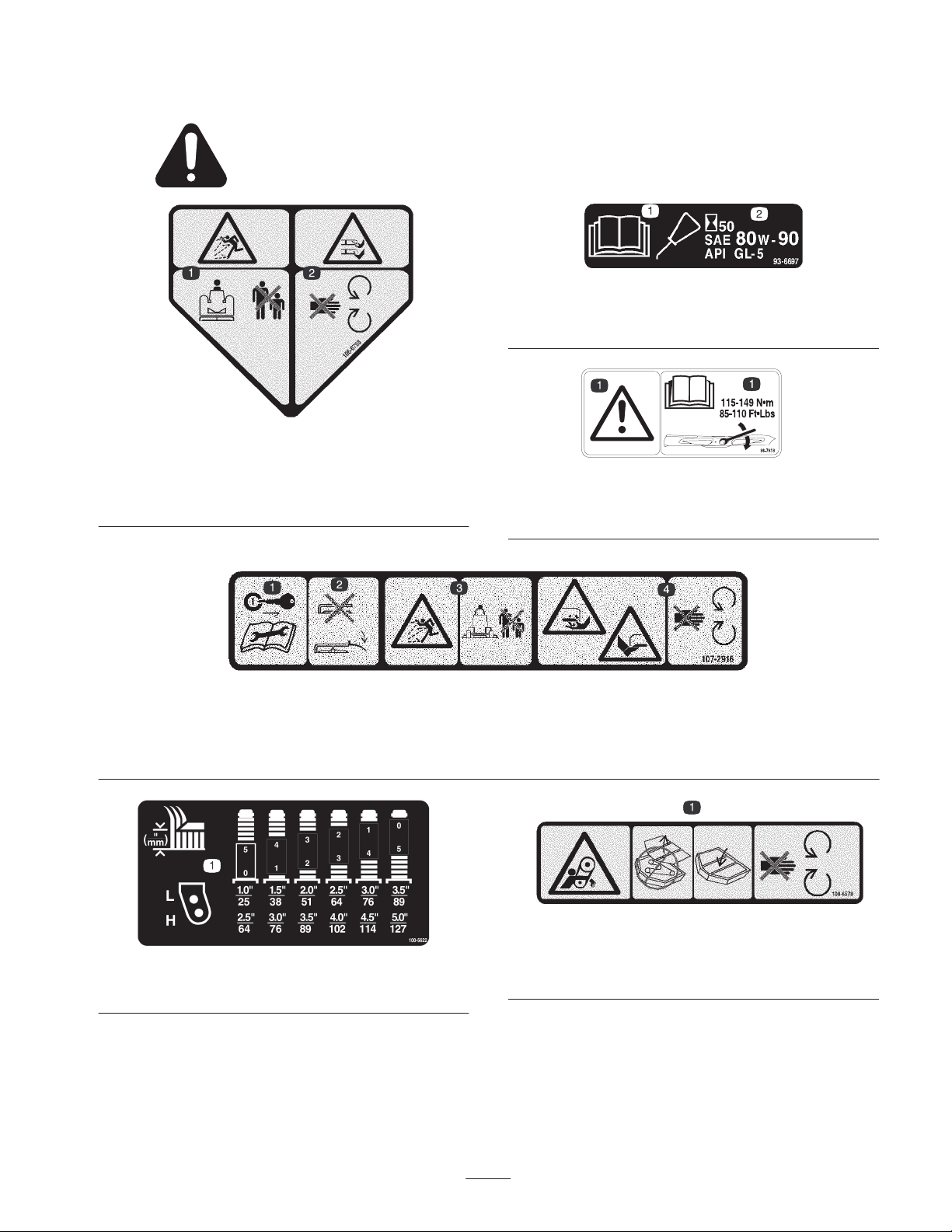
Safety and Instruction Decals
Safety decals and instructions are easily visible to the operator and are located near any area
of potential danger. Replace any decal that is damaged or lost.
106-6753
1. Thrown object
hazard—keep bystanders
a safe distance from the
machine.
2. Cutting/dismemberment
hazard of hand or foot,
mower blade—stay away
from moving parts.
93-6697
1. Read the Operator’s
Manual.
2. Add SAE 80w–90 (API
GL-5) oil every 50 hours.
93-7818
1. Danger—read the operator’s manual for blade torque
specification.
1. Remove the ignition key and
read the instructions before
servicing or performing
maintenance.
100-5622
1. Height of cut adjustment
2. Do not operate the mower
with the deflector up or
removed; keep the deflector
in place.
107-2916
3. Thrown object hazard—keep
bystanders a safe distance
from the machine.
1. Entanglement hazard, belt—do not operate the machine with
the shields or guards removed; always keep the shields and
guards in place. Stay away from moving parts.
4. Cutting/dismemberment
hazard of hand or foot,
mower blade—stay away
from moving parts
100-6578
7
Page 8
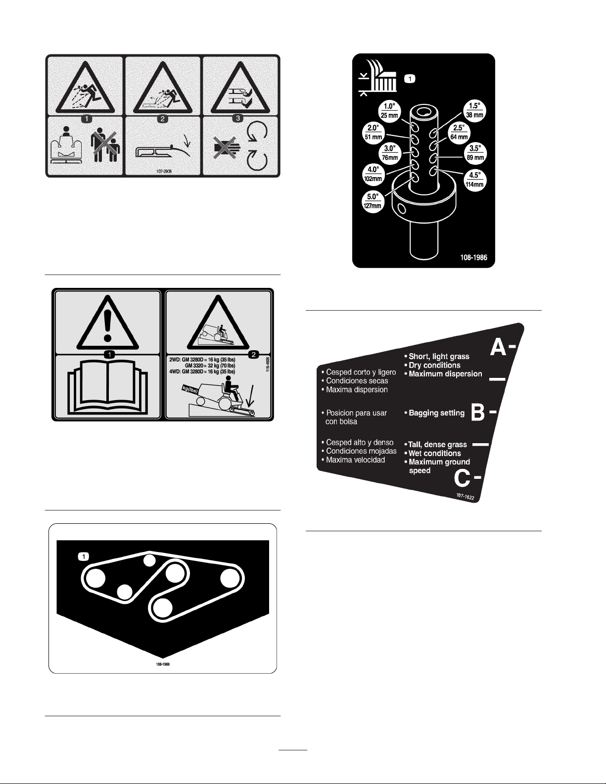
107-2908
1. Thrown object
hazard—keep bystanders
a safe distance from the
machine.
2. Thrown object hazard,
mower—keep the
deflector in place.
3. Cutting/dismemberment
hazard of hand or foot,
mower blade—stay away
from moving parts.
115-4505
1. Warning—read the Operator’s Manual.
2. Tipping hazard—lower the cutting unit when driving down
slopes. For 2 wheel drive units, add a 16 kg (35 lb) rear weight
to GM 3280D units and a 32 kg (70 lb) rear weight to GM 3320
units. For 4 wheel drive 3280 D units, add a 16 kg (32 lb) rear
weight.
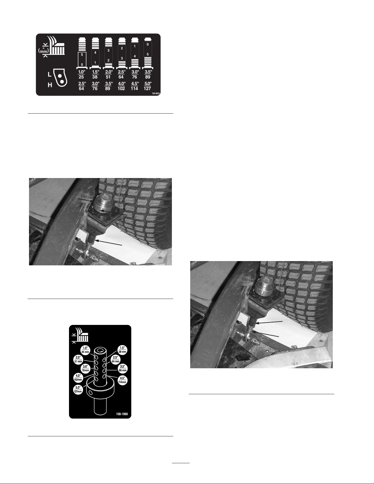
108-1986
1. Height of cut
1. Belt routing
107-1622
108-1988
8
Page 9

Specifications
Specifications
Width of cut 60 in. or 72 in. width of cut, 3 blades.
Height of cut
Construction Housing is made of 7 gauge steel and reinforced with channels and plates.
Cutter drive
Blades Three 1/4 in. thick, heat-treated steel
Suspension and castor
wheels
Anti-scalp features
Cutting unit covers Steel covers
Note: Specifications subject to change without notice.
1–5 in. (25–127 mm) adjustable in 1/2 in. (13 mm) increments. Height of cut adjustment is achieved by changing spacers on castor wheels and length of height of cut rod.
Isolation mounted gear box on cutting unit is driven by a PTO shaft. Power is
transmitted to the blades by one belt. Spindle shafts are supported by 2
greaseable, tapered roller bearings.
Cutting unit has two front castors, consisting of 8 in. x 3.5 in. pneumatic wheel and
tire assembly with sealed ball bearings. Rear of cutting unit is suspended from lift
arms with adjustment links for cutting unit rake.
Anti-scalp cup located on each blade. Anti-scalp rollers. Adjustable skid on each
end of cutting unit.
9
Page 10

Setup
Note: Determine the left and right sides of the machine from the normal operating position.
Loose Parts
Note: Use this chart as a checklist to ensure that all parts necessary for assembly have been received. Without these parts,
total setup cannot be completed. Some parts may have already been assembled at the factory.
Description
Discharge deflector assembly (rubber)
Screw, 5/16 x 7–1/2 in.
Spacer tube
Torsion spring
Flange nut, 5/16
Pivot pin assembly
Cotter pin
Lift arm R.H.
Lift arm L.H.
Thrust washer–nylon
Clevis pin
Hair pin
Height of cut collar
Clevis pin
Hair pin
Capscrew, 1/2 x 3/4 in.
Washer
Qty. Use
1
1
1
1
1
2
2
1
1
4
4
2
2
2
2
2
2
Mount to side of cutting unit
(Model 30368 only)
Mount lift arms to traction unit
Mount cutting unit to lift arms
CE certificate
Parts catalog
Operator’s manual 1 Read before operating the machine.
1
1
10
Page 11

Danger
2. Install the bolt and nut. Place the right hand J hook end
of the spring around the grass deflector (Fig. 1).
If the engine is started and the PTO shaft is
allowed to rotate, serious injury could result.
Do not start the engine and engage the PTO lever
when the PTO shaft is not connected to the gear
box on the cutting unit.
Mount the Grass Deflector
(Model 30368 only)
Warning
An uncovered discharge opening could allow the
lawn mower to throw objects in the operator’s or
bystander’s direction and result in serious injury.
Also, contact with the blade could occur.
• Never operate the lawn mower unless you install
a cover plate, a mulch plate, or a grass chute
and catcher.
• Make sure the grass deflector is in the down
position.
1. Place the spacer and spring between the grass deflector
brackets (Fig. 1). Place the left hand J hook end of the
spring behind the deck edge.
Note: Make sure the left hand J hook end of the spring is
installed behind the deck edge before installing the bolt as
shown in figure 1.
Important The grass deflector must be able to lower
down into position. Lift the deflector up to test that it
lowers into the full down position.
Installing the Lift Arms to the
Traction Unit
1. On one side of the traction unit, loosen (do not remove)
the wheel nuts securing the wheel and tire assembly to
the front wheel studs.
2. Jack up the machine until the front wheel is off of the
floor. Use jack stands or block the machine to prevent it
from accidentally falling.
3. Remove the wheel nuts and slide the wheel and tire
assembly off of the studs.
4. Mount a lift arm to the pivot bracket with a pivot pin
and cotter pin (Fig. 2). The lift arms ends are to be
positioned so the ends curve outward.
5. Mount the rear of the lift arm to the lift cylinder with a
pivot pin and (2) cotter pins (supplied with the traction
unit).
6. Hook the brake return spring to the hole in the lift arm
(Fig. 2).
2
6
1
1. Bolt
2. Spacer
3. Locknut
4. Spring
5. Spring installed
2
Figure 1
4
8
7
3
8
7
6. Grass Deflector
7. Left hand hook end of
spring, place behind deck
edge before installing bolt
8. Right hand hook end of
spring
1
Figure 2
1. Pivot pin
2. Lift arm
5
7. Install the wheel and tire assembly. Torque the wheel
nuts to 45–55 ft.-lb. (61–75 N⋅m).
8. Repeat the procedure on the opposite side of the
machine.
11
3
3. Pivot bracket
4. Brake return spring
4
Page 12

Connecting the Lift Arms to the
Cutting Unit
1. Move the cutting unit into position in front of the
traction unit.
2. Move the lift lever to the Float position. Push a lift arm
down until the holes in the lift arm line up with the
holes in the castor arm bracket and the height of cut rod
can be inserted into the lift arm pads (Fig. 3).
6. Push down on the rear of the cutting unit and insert the
height of cut rods through the lift arm pads.
7. Install the height of cut collars onto the height of cut
rods and secure with the clevis pins and hair pin cotters
(Fig. 3). Position the head of the clevis pin toward the
front of the deck, if possible.
8. Install a 1/2 x 3/4” capscrew and a washer to top of
each height of cut rod (Fig. 3).
3. Secure the lift arm to the castor arm with (2) thrust
washers, a clevis pin and a hair pin cotter. Position the
thrust washers between the lift arm and the castor arm
bracket (Fig. 3). Insert end of cotter pin into the slot in
the castor arm tab to retain cotter pin.
9
10
1
67
5
2
3
8
4
11
Connecting the PTO Shaft to
the Cutting Unit Gear Box
1. Slide the male PTO shaft into the female PTO shaft.
Align the mounting holes in the gear case input shaft
with the holes in the PTO shaft and slide them together.
2
4
1
2
Figure 4
1. PTO shaft
2. Bolts and locknuts
3. Gear case
4. Roll pin
Figure 3
1. Lift arm
2. Castor arm bracket
3. Height of cut rod
4. Lift arm pads
5. Thrust washers
6. Clevis pin
4. Repeat the procedure on the opposite lift arm.
5. Start the traction unit and raise the cutting unit.
7. Hair pin cotter
8. Height of cut collar
9. Clevis pin
10. Hair pin cotter
11. Capscrew
2. Secure them with a roll pin.
3. Tighten the capscrews and nuts.
Greasing the Machine
Before the machine is operated, it must be greased to
ensure proper lubricating characteristics; refer to Greasing
the Bearings and Bushings. Failure to properly grease the
machine will result in premature failure of critical parts.
12
Page 13

Before Operating
Caution
If you leave the key in the ignition switch, someone
could accidently start the engine and seriously
injure you or other bystanders.
Remove the key from the ignition before you do
any maintenance.
Checking the Lubricant in the
Gear Box
The gear box in designed to operate on SAE 80–90 wt. gear
lube. Although the gear box is shipped with lubricant from
the factory, check the level before operating the cutting
unit.
1. Position the machine and cutting unit on a level surface.
2. Remove the dipstick/fill plug from the top of the gear
box (Fig. 5) and make sure that the lubricant is between
the marks on the dipstick. If the lubricant level is low,
add enough lubricant until the level is between the
marks.
1. Start the engine and raise the cutting unit off the floor
so that the height-of-cut can be changed. Stop the
engine and remove the key after the cutting unit is
raised.
2. Position the castor wheel axles in the same holes in both
castor forks. Refer to figure 7 to determine the correct
holes for the setting.
Note: When operating in 2–1/2 inch (64 mm) height of cut
or higher, the axle bolt must be installed in the lower castor
fork hole to prevent grass buildup between the wheel and
the fork. When operating in height of cuts lower than 2–1/2
inches (64 mm) and grass buildup is detected, reverse the
machines direction to pull any clippings away from the
wheel/fork area.
3. Remove the tensioning cap from the spindle shaft
(Fig. 6) and slide the spindle out of the castor arm. Put
the 2 shims (1/8 inch) onto the spindle shaft as they
were originally installed. These shims are required to
achieve a level across the entire width of the cutting
units. Slide the appropriate number of 1/2 inch spacers
onto the spindle shaft to get the desired height-of-cut;
then slide the washer onto the shaft.
Refer to figure 7 to determine the combinations of spacers
for the setting.
2
1
Figure 5
1. Dipstick/fill plug
Adjusting the Height-of-Cut
The height-of-cut is adjustable from 1 to 5 inches (25 to
127 mm) in 1/2 inch (13 mm) increments. To adjust the
height-of-cut, position the castor wheel axles in the upper
or lower holes of the castor forks, add or remove an equal
number of spacers from the castor forks and secure the
height of cut collar to the desired holes in the height of cut
rod.
4
1
1. Castor wheel
2. Tensioning cap
3. Spacers
3
5
Figure 6
4. Shims
5. Axle mounting holes
13
Page 14
7. Secure the adjustment with the clevis pin and hair pin.
Note: Position the head of the clevis pin toward the front
of the deck, if possible.
Note: When using 1 in. (25 mm), 1-1/2 in. (38 mm), or
occasionally 2 in. (51 mm) height–of–cut, move the skids
and roller to the highest holes.
Figure 7
4. Push the castor spindle through the castor arm. Install
the shims (as they were originally installed) and the
remaining spacers onto the spindle shaft. Install the
tensioning cap to secure the assembly.
5. Remove the hair pin and clevis pin securing the height
of cut collar to the height of cut rod on the rear of the
cutting unit (Fig. 8).
2
3
1
Figure 8
1. Height-of-cut rod
2. Height of cut collar
3. Clevis pin & hair pin
Adjust the Cutting Unit Pitch
Measuring the Cutting Unit Pitch
Cutting unit pitch is the difference in height-of-cut from the
front of the blade plane to the back of the blade plane. Toro
recommends a blade pitch of 1/4 in. (6 mm). That is the
back of the blade plane is 1/4 in. (6 mm) higher than the
front.
1. Position the machine on a level surface on the shop
floor.
2. Set the cutting unit to the desired height-of-cut.
3. Rotate 1 blade so that it points straight forward.
4. Using a short ruler, measure from the floor to the front
tip of the blade. Rotate the blade tip to the rear and
measure from the floor to the tip of the blade.
5. Subtract the front dimension from the rear dimension to
calculate the blade pitch.
6. Loosen the jam nuts on the bottom of the height-of-cut
rods (Fig. 10).
6. Align the height-of-cut collar to the desired
height-of-cut holes on the height of cut rod (Fig. 9).
Figure 9
1
2
Figure 10
1. Height-of-cut rod 2. Jam nut
7. Rotate the height-of-cut rods to raise or lower the rear
of the cutting unit and attain the correct cutting unit
pitch.
8. Tighten the jam nuts.
14
Page 15

Adjusting the Skids
The skids should be mounted in the lower position when
operating in height of cuts greater than 2-1/2 inches
(64 mm) and in the higher position when operating in
height of cuts lower than 2-1/2 inches (64 mm).
Adjust the skids by removing the flange bolt and nuts,
positioning them as desired, and installing the fasteners
(Fig. 11).
2. Select a hole so the anti–scalp roller is positioned to the
nearest corresponding height-of-cut desired (Fig. 13).
Figure 13
3. Install the flange nut, bushing, spacer, and bolt. Torque
to 40–45 ft–lb (54–61 N⋅m) (Fig. 12).
1
Figure 11
1. Skid
Adjusting the Anti-Scalp
Rollers
Whenever you change the height-of-cut, it is recommended
to adjust the height of the anti-scalp rollers.
1. After adjusting the height-of-cut, adjust the rollers by
removing the flange nut, bushing, spacer, and bolt
(Fig. 12).
1
5
1. Anti–scalp roller
2. Spacer
3. Bushing
3
Figure 12
4. Flange Nut
5. Bolt
2
1
Adjusting the Rollers
Note: If the cutting unit is to be used in the 1 or 1-1/2 in.
(25 or 38 mm) height-of-cut setting, the cutting unit rollers
must be repositioned in the top bracket holes.
To adjust the front rollers (Fig. 14)
1. Remove the screw and nut securing the roller shaft to
the deck bracket .
2
1
Figure 14
1. Roller 2. Roller shaft
2. Slide the shaft out of the lower bracket holes, align the
roller with the top holes, and install the shaft.
3. Install the screw and nut to secure the assemblies.
15
Page 16

To adjust the rear (internal) rollers (Fig. 15)
1. Remove the lock nuts securing the roller shafts to the
underside of the deck.
2. Adjust the baffle and cam locks in the slots to the
desired discharge flow.
3. Swing the lever back over to tighten the baffle and cam
locks.
4. If the cams do not lock the baffle into place or it is too
tight, loosen the lever and then rotate the cam lock.
Adjust the cam lock until the desired locking pressure is
achieved.
Figure 15
1. Internal rollers
2. Slide the shafts out of the lower bracket holes, align the
rollers with the top holes and install the shafts.
3. Install the lock nuts to secure the assemblies.
Adjusting the Flow Baffle
The mower discharge flow can be adjusted for different
types of mowing conditions. Position the cam locks and
baffle to give the best quality of cut.
1. To adjust the cam locks, swing the lever up to loosen
the cam lock (Fig. 16).
1
Positioning the Flow Baffle
The following figures are only recommendations for use.
Adjustments will vary by grass type, moisture content, and
height of grass.
Note: If the engine power draws down and the mower
ground speed is the same, open up the baffle.
Position A
This is the full rear position. The suggested use for this
position is a follows.
• Use for short, light grass mowing conditions.
• Use in dry conditions.
• For smaller grass clippings.
• Propels grass clippings farther away from the mower.
Full Rearward Position
1
4
Figure 16
1. Cam lock
2. Lever
3. Rotate cam to increase or
decrease locking
pressure
4. Slot
m–6829
1
Figure 17
2
3
m–6823
16
Page 17

Position B
Use this position when bagging.
Middle Position
3. Check and adjust all castor tire pressures to 50 psi
(345 kPa).
4. Check for bent blades; refer to Checking for a Bent
Blade, page 23.
5. Cut grass in a test area to determine if all cutting units
are cutting at the same height.
6. If cutting unit adjustments are still needed, find a flat
surface using a 6 foot (2 m) or longer straight edge.
7. To ease measuring blade plane, raise the height of cut to
the highest position; refer to Adjusting the Height of
Cut.
m–6828
Figure 18
Position C
This is the full open position. The suggested use for this
position is as follows.
• Use in tall, dense grass mowing conditions.
• Use in wet conditions.
• Lowers the engine power consumption.
• Allows increased ground speed in heavy conditions.
Full Forward Position
8. Lower cutting unit onto the flat surface. Remove the
covers from the top of the cutting units
9. Rotate the blade on each spindle until the ends face
forward and backward.
10. Measure from the floor to the front tip of the cutting
edge.
11. Adjust 1/8 in. shims on castor fork(s) to match height of
cut to decal (Fig. 20); refer to Adjusting the Cutting
Unit Pitch.
2
3
4
m–6827
Figure 19
Correcting Cutting Unit
Mismatch
Due to differences in grass conditions and the
counterbalance setting of the traction unit, it is advised that
grass be cut and appearance checked before formal cutting
is started.
1. Set the cutting unit to the desired height of cut; refer to
Adjusting the Height of Cut, page 13.
2. Check and adjust front and rear tractor tire pressure to
25–30 psi (172–207 kPa).
1. Castor wheel
2. Tensioning cap
3. Spacers
17
5
1
Figure 20
4. Shims
5. Axle mounting holes
Page 18

Operation
Note: Determine the left and right sides of the machine
from the normal operating position.
Using the Side Discharge
to maintain the same height-of-cut, which is a good
practice, you will need to cut more frequently in early
spring; as the grass growth rate slows in mid summer, cut
only every 8–10 days. If you are unable to mow for an
extended period due to weather conditions or other reasons,
mow first with the height-of-cut at a high level; then mow
again 2–3 days later with a lower height setting.
The mower has a hinged grass deflector that disperses
clippings to the side and down toward the turf.
Danger
Without the grass deflector, discharge cover, or
complete grass catcher assembly mounted in place,
you and others are exposed to blade contact and
thrown debris. Contact with rotating mower
blade(s) and thrown debris will cause injury or
death.
• Never remove the grass deflector from the
mower because the grass deflector routes
material down toward the turf. If the grass
deflector is ever damaged, replace it
immediately.
• Never put your hands or feet under the mower.
• Never try to clear the discharge area or mower
blades unless you move the power take off
(PTO) to the off position, rotate the ignition key
to off and remove the key.
• Make sure the grass deflector is in the down
position.
Always Mow with Sharp Blades
A sharp blade cuts cleanly and without tearing or shredding
the grass blades like a dull blade. Tearing and shredding
causes the grass to turn brown at the edges which impairs
growth and increases susceptibility to diseases.
After Operating
To ensure optimum performance, clean the underside of the
mower housing after each use. If residue is allowed to build
up in the mower housing, cutting performance will
decrease.
Cutting Unit Pitch
We recommend a blade pitch of 1/4 in. (6 mm). A pitch
larger than 1/4 in. (6 mm) will result in less power required,
larger clippings, and a poorer quality of cut. A pitch less
than 1/4 in. (6 mm) will result in more power required,
smaller clippings and a better quality of cut.
Operating Tips
Mow When Grass is Dry
Mow either in the late morning to avoid the dew, which
causes grass clumping, or in late afternoon to avoid the
damage that can be caused by direct sunlight on the
sensitive, freshly mowed grass.
Select the Proper Height-of-Cut Setting to
Suit Conditions
Remove approximately 1 in. (25 mm) or no more than 1/3
of the grass blade when cutting. In exceptionally lush and
dense grass, you may have to raise the height-of-cut to the
next setting.
Mow at Proper Intervals
Under most normal conditions you will need to mow
approximately every 4–5 days. But remember, grass grows
at different rates at different times. This means that in order
18
Page 19
Maintenance
Recommended Maintenance Schedule
Maintenance Service
Interval
After first 2 hours • Tighten the castor wheel nuts.
After first 10 hours
Daily
Every 50 hours
Every 400 hours • Change the gear box oil.
1
Immediately after every washing, regardless of the interval listed
Maintenance Procedure
• Tighten the castor wheel nuts.
• Torque the blade bolts.
• Check the blades.
• Lubricate the castor arm bushings.
• Lubricate the castor wheel bearings.
• Tighten the castor wheel nuts.
• Torque the blade bolts.
• Lubricate the grease fittings.
• Clean under the cutting unit belt covers.
• Check the blade drive belt adjustment.
• Check the gear box oil level.
Caution
1
1
1
If you leave the key in the ignition switch, someone
could accidentally start the engine and seriously
injure you or other bystanders.
Remove the key from the ignition switch before
you do any maintenance.
Greasing the Bearings,
Bushings and Gear Box
The machine has grease fittings that must be lubricated
regularly with No. 2 General Purpose Lithium Base Grease.
If the machine is operated under normal conditions,
lubricate all bearings and bushings after every 50 hours of
operation or immediately after every washing.
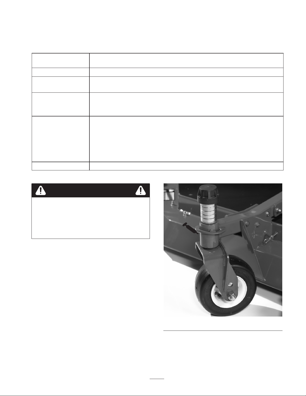
The grease fitting locations and quantities are:
• Castor fork shaft bushings (2) (Fig. 21)
• Spindle shaft bearings (3) (located under the pulley)
(Fig. 22)
• Idler arm shaft bearings (Fig. 22)
• Lift arm pivots–front (2) (Fig. 23)
Figure 21
• Lift arm pivots–rear (2) (Fig. 24)
19
Page 20

Figure 22
2. Position the machine and cutting unit on a level surface
and lower the cutting unit. Remove the dipstick/fill plug
from the top of the gear box (Fig. 25) and make sure
that the lubricant is between the marks on the dipstick.
If the lubricant level is low, add SAE 80–90 wt. gear
lube until the level is between the marks.
1
Figure 25
1. Fill/check plug
Figure 23
Figure 24
20
Page 21

Separating the Cutting Unit
from the Traction Unit
1. Position the machine on level surface, lower the cutting
unit to the floor, move the lift lever to the Float
position, shut the engine off, and engage the parking
brake.
2. Remove the capscrew and washer mounted to the top of
each height of cut rod (Fig. 8).
3. Remove the hairpin and clevis pin securing the height
of cut collar to the height of cut rod on the rear of the
cutting unit (Fig. 8). Remove the height of cut collar.
5. Roll the cutting unit away from the traction unit,
separating the male and female sections of the PTO
shaft (Fig. 28).
1
2
3
4
1
Figure 26
1. Height-of-cut rod
2. Capscrew & washer
4. Remove the hair pin cotters and clevis pins securing
the lift arms to the castor arm brackets (Fig. 27).
3. Height of cut collar
4. Hair pin & clevis pin
1
Figure 28
1. PTO shaft
Danger
If the engine is started and the PTO shaft is
allowed to rotate, serious injury could result.
Do not start the engine and engage the PTO lever
when the PTO shaft is not connected to the gear
box on the cutting unit.
Mounting the Cutting Unit to
the Traction Unit
1. Position the machine on a level surface and shut the
engine off.
1
2
1. Lift arm
2. Clevis pin
3
Figure 27
3. Hair pin cotter
4. Castor arm bracket
2. Move the cutting unit into position in front of the
traction unit.
3. Slide the male PTO shaft into the female PTO shaft
(Fig. 28).
4. Move the lift lever to the Float position. Push a lift arm
4
21
down until the holes in the lift arm line up with the
holes in the castor arm bracket and the height of cut rod
can be inserted into the lift arm pads (Fig. 29).
5. Secure the lift arm to the castor arm with (2) thrust
washers, a clevis pin and a hair pin cotter. Position the
thrust washers between the lift arm and the castor arm
bracket (Fig. 29). Insert end of cotter pin into the slot in
the castor arm tab to retain cotter pin.
Page 22

9
10
1
67
5
2
3
11
8
4
Servicing the Castor Arm
Bushings
The castor arms have bushings pressed into the top and
bottom of the tube and after many hours of operation, the
bushings will wear. To check the bushings, move the castor
fork back and forth and from side to side. If the castor
spindle is loose inside the bushings, the bushings are worn
and must be replaced.
1. Raise the cutting unit so that the wheels are off of the
floor. Block the cutting unit so that it cannot
accidentally fall.
2. Remove the tensioning cap, spacer(s), and thrust washer
from the top of the castor spindle.
3. Pull the castor spindle out of the mounting tube. Allow
the thrust washer and spacer(s) to remain on the bottom
of the spindle.
4. Insert a pin punch into the top or bottom of the
mounting tube and drive the bushing out of the tube
(Fig. 30). Also drive the other bushing out of the tube.
Clean the inside of the tubes to remove dirt.
Figure 29
1. Lift arm
2. Castor arm bracket
3. Height of cut rod
4. Lift arm pads
5. Thrust washers
6. Clevis pin
6. Repeat the procedure on the opposite lift arm.
7. Start the traction unit and raise the cutting unit.
8. Push down on the rear of the cutting unit and insert the
height of cut rods through the lift arm pads.
9. Install the height of cut collars onto the height of cut
rods and secure with the clevis pins and hair pin cotters
(Fig. 29). Head of clevis pin to be positioned toward the
front of the deck.
10. Install a 1/2 x 3/4” capscrew and a washer to top of
each height of cut rod (Fig. 29).
7. Hair pin cotter
8. Height of cut collar
9. Clevis pin
10. Hair pin cotter
11. Capscrew
1
Figure 30
1. Castor arm tube 2. Bushings
5. Apply grease to the inside and outside of the new
bushings. Using a hammer and flat plate, drive the
bushings into the mounting tube.
6. Inspect the castor spindle for wear and replace it if it is
damaged.
7. Push the castor spindle through the bushings and
mounting tube. Slide the thrust washer and spacer(s)
onto the spindle. Install the tensioning cap on the castor
spindle to retain all parts in place.
2
Servicing the Castor Wheels
and Bearings
1. Remove the locknut from the capscrew holding the
castor wheel assembly between the castor fork (Fig. 31)
. Grasp the castor wheel and slide the capscrew out of
the fork or pivot arm.
22
Page 23

2. Remove the bearing from the wheel hub and allow the
bearing spacer to fall out (Fig. 31). Remove the bearing
from the opposite side of the wheel hub.
3. Check the bearings, spacer, and inside of the wheel hub
for wear. Replace any damaged parts.
4. To assemble the castor wheel, push the bearing into the
wheel hub. When installing the bearings, press on the
outer race of the bearing.
5. Slide the bearing spacer into the wheel hub. Push the
other bearing into the open end of the wheel hub to
captivate the bearing spacer inside the wheel hub.
6. Install the castor wheel assembly between the castor
fork and secure it in place with the capscrew and
locknut.
2
1
3. Rotate the opposite end of the blade forward. Measure
between the cutting unit and cutting edge of the blade at
the same position as in step 2. The difference between
the dimensions obtained in steps 2 and 3 must not
exceed 1/8 in. (3 mm). If the dimension exceeds 1/8 in.
(3 mm), the blade is bent and must be replaced; refer to
Removing the Cutter Blade, page 23.
Removing and Installing the
Cutter Blade(s)
The blade must be replaced if a solid object is hit, the blade
is out of balance, or if the blade is bent. Always use
genuine Toro replacement blades to be sure of safety and
optimum performance. Never use replacement blades made
by other manufacturers because they could be dangerous.
1. Raise the cutting unit to the highest position, engage the
parking brake, stop the engine, and remove the ignition
key. Block the cutting unit to prevent it from
accidentally falling.
2. Grasp the end of the blade using a rag or thickly padded
glove. Remove the blade bolt, anti-scalp cup, and blade
from the spindle shaft (Fig. 33).
3
4
Figure 31
1. Castor wheel
2. Castor fork
3. Bearing (2)
4. Bearing spacer
Checking for a Bent Blade
1. Position the machine on a level surface. Raise the
cutting unit, engage the parking brake, put the traction
pedal in neutral, put the PTO lever in the Off position,
stop the engine, and remove the ignition key. Block the
cutting unit to prevent it from accidentally falling.
2. Rotate the blade until the ends face forward and
backward (Fig. 32). Measure from the inside of the
cutting unit to the cutting edge at the front of the blade.
Remember this dimension.
Figure 32
2
1
Figure 33
1. Blade bolt 2. Anti-scalp cup
3. Install the blade, anti-scalp cup, and blade bolt. Tighten
the blade bolt to 85–110 ft.-lb. (115–149 N⋅m).
23
Page 24

Important The curved part of the blade must be
pointing toward the inside of the cutting unit to ensure
proper cutting.
Inspecting and Sharpening the
A
FLAT PART
OF BLADE
SAIL
Cutter Blade(s)
Danger
A worn or damaged blade can break, and a piece
of the blade could be thrown into the operator’s or
bystander’s area, resulting in serious personal
injury or death. Trying to repair a damaged blade
may result in discontinued safety certification of
the product.
• Inspect the blade periodically for wear or
damage.
• Never try to straighten a blade that is bent or
weld a broken or cracked blade.
• Replace a worn or damaged blade.
Two areas must be considered when checking and servicing
the cutter blade—the sail and the cutting edge. Both cutting
edges and the sail, which is the turned up portion opposite
the cutting edge, contribute to a good quality-of-cut. The
sail is important because it lifts the grass up straight,
thereby producing an even cut. However, the sail will
gradually wear down during operation, and this condition is
normal. As the sail wears down, the quality-of-cut will
degrade somewhat, although the cutting edges are sharp.
The cutting edge of the blade must be sharp so that the
grass is cut rather than torn. A dull cutting edge is evident
when the tips of the grass appear brown and shredded.
Sharpen the cutting edges to correct this condition.
1. Position the machine on a level surface. Raise the
cutting unit, engage the parking brake, put the traction
pedal in neutral, put the PTO lever in the Off position,
stop the engine, and remove the ignition key.
SAIL
B
WEAR
SAIL
C
SLOT
FORMED
Figure 34
Danger
If the blade is allowed to wear, a slot will form
between the sail and flat part of the blade
(Fig. 34-C). Eventually a piece of the blade may
break off and be thrown from under the housing,
possibly resulting in serious injury to you or
bystanders.
• Inspect the blade periodically for wear or
damage.
• Never try to straighten a blade that is bent or
weld a broken or cracked blade.
• Replace a worn or damaged blade.
SHARPEN AT THIS
ANGLE ONLY
2. Examine the cutting ends of the blade carefully,
especially where the flat and curved parts of the blade
meet (Fig. 34-A). Since sand and abrasive material can
wear away the metal that connects the flat and curved
parts of the blade, check the blade before using the
mower. If wear is noticed (Fig. 34-B), replace the blade.
3. Examine the cutting edges of all of the blades. Sharpen
the cutting edges if they are dull or nicked. Sharpen
only the top of the cutting edge and maintain the
original cutting angle to make sure of sharpness
(Fig. 35). The blade will remain balanced if the same
amount of metal is removed from both cutting edges.
Note: Remove the blades and sharpen them on a grinder.
After sharpening the cutting edges, install the blade with
the anti-scalp cup and blade bolt; refer to Removing and
Installing the Cutter Blade(s), page 23.
END VIEW OF
BLADE
Figure 35
Correcting Cutting Unit
Mismatch
If there is mismatch between the blades, the grass will
appear streaked when it is cut. This problem can be
corrected by making sure that the blades are straight and all
of the blades are cutting on the same plane.
1. Using a 3 foot (1 meter) long carpenters level, find a
level surface on the shop floor.
24
Page 25

2. Raise the height-of-cut to the highest position; refer to
Adjusting the Height-Of-Cut, page 13.
3. Lower the cutting unit onto the flat surface. Remove the
covers from the top of the cutting unit.
4. Rotate the blades until the ends face forward and
backward. Measure from the floor to the front tip of the
cutting edge. Remember this dimension. Then rotate the
same blade so that the opposite end is forward, and
measure again. The difference between the dimensions
must not exceed 1/8 in. (3 mm). If the dimension
exceeds 1/8 in. (3 mm), replace the blade because it is
bent. Make sure to measure all of the blades.
1
5. Compare the measurements of the outer blades with the
the center blade. The center blade must not be more
than 3/8 in. (10 mm) lower than the outer blades. If the
center blade is more than 3/8 in. (10 mm) lower than the
outer blades, proceed to step 6 and add shims between
the spindle housing and the bottom of the cutting unit.
6. Remove the capscrews, flat washers, lock washers, and
nuts from the outer spindle in the area where the shims
must be added. To raise or lower the blade, add a shim,
Part No. 3256-24, between the spindle housing and the
bottom of the cutting unit. Continue to check the
alignment of the blades and add shims until the tips of
the blades are within the required dimension.
Important Do not use more than three shims at any one
hole location. Use decreasing numbers of shims in adjacent
holes if more than one shim is added to any one hole
location.
7. Install the belt covers.
Replacing the Drive Belt
The blade drive belt, tensioned by the spring loaded idler
pulley, is very durable. However, after many hours of use,
the belt will show signs of wear. Signs of a worn belt are:
squealing when belt is rotating, blades slipping when
cutting grass, frayed edges, burn marks and cracks. Replace
the belt if any of these conditions are evident.
Figure 36
1. Idler pulley
1
Figure 37
1. Gearbox
3. Remove the old belt from around the spindle pulleys
and idler pulley.
4. Route the new belt around the spindle pulleys and idler
pulley assembly as shown in figure 38.
1. Lower the cutting unit to the shop floor. Remove the
belt covers from the top of the cutting unit and set the
covers aside.
2. Using a torque wrench or similar tool, move the idler
pulley (Fig. 36) away from the drive belt to release the
belt tension and allow the belt to be slipped off the
gearbox pulley (Fig. 37).
Figure 38
5. Install the belt covers.
25
Page 26

Replacing the Grass Deflector
4. Install the bolt and nut. Place the right hand J hook end
of the spring around the grass deflector (Fig. 39).
Warning
An uncovered discharge opening could allow the
lawn mower to throw objects in the operator’s or
bystander’s direction and result in serious injury.
Also, contact with the blade could occur.
• Never operate the lawn mower unless you install
a cover plate, a mulch plate, or a grass chute
and catcher.
• Make sure the grass deflector is in the down
position.
1. Position the machine on a level surface, raise the cutting
unit, engage the parking brake, put the traction pedal in
neutral, the PTO lever in the Off position, shut the
engine off, and remove the ignition key. Block the
cutting unit to prevent it from accidentally falling.
2. Remove the locknut, bolt, spring and spacer holding the
deflector to the pivot brackets (Fig. 39). Remove
damaged or worn grass deflector.
3. Place the spacer and spring between the grass deflector
brackets (Fig. 39). Place the left hand J hook end of the
spring behind the deck edge.
Important The grass deflector must be able to lower
down into position. Lift the deflector up to test that it
lowers into the full down position.
Note: Make sure the left hand J hook end of the spring is
installed behind the deck edge before installing the bolt as
shown in figure 39.
2
4
6
8
7
1
3
8
7
Figure 39
1. Bolt
2. Spacer
3. Locknut
4. Spring
5. Spring installed
6. Grass Deflector
7. Left hand hook end of
spring, place behind deck
edge before installing bolt
8. Right hand hook end of
spring
5
26
Page 27

27
Page 28

The Toro General Commercial Products Warranty
A Two-Year Limited Warranty
Conditions and Products Covered
The Toro Company and its affiliate, Toro Warranty Company,
pursuant to an agreement between them, jointly warrant your Toro
Commercial Product (“Product”) to be free from defects in
materials or workmanship for two years or 1500 operational
hours*, whichever occurs first. Where a warrantable condition
exists, we will repair the Product at no cost to you including
diagnosis, labor, parts, and transportation. This warranty begins
on the date the Product is delivered to the original retail purchaser.
* Product equipped with hour meter
Instructions for Obtaining Warranty Service
You are responsible for notifying the Commercial Products
Distributor or Authorized Commercial Products Dealer from whom
you purchased the Product as soon as you believe a warrantable
condition exists.
If you need help locating a Commercial Products Distributor or
Authorized Dealer, or if you have questions regarding your
warranty rights or responsibilities, you may contact us at:
Toro Commercial Products Service Department
Toro Warranty Company
8111 Lyndale Avenue South
Bloomington, MN 55420-1196
952-888-8801 or 800-982-2740
E-mail: commercial.service@toro.com
Owner Responsibilities
As the Product owner, you are responsible for required maintenance and adjustments stated in your operator’s manual. Failure
to perform required maintenance and adjustments can be grounds
for disallowing a warranty claim.
Items and Conditions Not Covered
Not all product failures or malfunctions that occur during the
warranty period are defects in materials or workmanship. This
express warranty does not cover the following:
• Product failures which result from the use of non-Toro
replacement parts, or from installation and use of add-on,
modified, or unapproved accessories
• Product failures which result from failure to perform required
maintenance and/or adjustments
• Product failures which result from operating the Product in an
abusive, negligent or reckless manner
• Parts subject to consumption through use unless found to be
defective. Examples of parts which are consumed, or used up,
during normal Product operation include, but are not limited to,
blades, reels, bedknives, tines, spark plugs, castor wheels,
tires, filters, belts, and certain sprayer components such as
diaphragms, nozzles, and check valves, etc.
• Failures caused by outside influence. Items considered to be
outside influence include, but are not limited to, weather,
storage practices, contamination, use of unapproved coolants,
lubricants, additives, or chemicals, etc.
• Normal “wear and tear” items. Normal “wear and tear” includes,
but is not limited to, damage to seats due to wear or abrasion,
worn painted surfaces, scratched decals or windows, etc.
Parts
Parts scheduled for replacement as required maintenance are
warranted for the period of time up to the scheduled replacement
time for that part.
Parts replaced under this warranty become the property of Toro.
Toro will make the final decision whether to repair any existing part
or assembly or replace it. Toro may use factory remanufactured
parts rather than new parts for some warranty repairs.
General Conditions
Repair by an Authorized Toro Distributor or Dealer is your sole
remedy under this warranty.
Neither The Toro Company nor Toro Warranty Company is
liable for indirect, incidental or consequential damages in
connection with the use of the Toro Products covered by this
warranty, including any cost or expense of providing substitute equipment or service during reasonable periods of
malfunction or non-use pending completion of repairs under
this warranty. Except for the Emissions warranty referenced
below, if applicable, there is no other express warranty. All
implied warranties of merchantability and fitness for use are
limited to the duration of this express warranty.
Some states do not allow exclusions of incidental or consequential
damages, or limitations on how long an implied warranty lasts, so
the above exclusions and limitations may not apply to you.
This warranty gives you specific legal rights, and you may also
have other rights which vary from state to state.
Note regarding engine warranty: The Emissions Control System
on your Product may be covered by a separate warranty meeting
requirements established by the U.S. Environmental Protection
Agency (EPA) and/or the California Air Resources Board (CARB).
The hour limitations set forth above do not apply to the Emissions
Control System Warranty. Refer to the Engine Emission Control
Warranty Statement printed in your operator’s manual or contained in the engine manufacturer’s documentation for details.
Countries Other than the United States or Canada
Customers who have purchased Toro products exported from the United States or Canada should contact their Toro Distributor (Dealer)
to obtain guarantee policies for your country, province, or state. If for any reason you are dissatisfied with your Distributor’s service or
have difficulty obtaining guarantee information, contact the Toro importer. If all other remedies fail, you may contact us at Toro Warranty
Company.
Part No. 374-0031 Rev. C
 Loading...