

Page 1

60in,62in,and72inRotary
Mowers
FormNo.3389-362RevA
Groundsmaster
®
360Seriesand7200Series
TractionUnit
ModelNo.30353—SerialNo.315000001andUp
ModelNo.30354—SerialNo.315000001andUp
ModelNo.30456—SerialNo.315000001andUp
ModelNo.30457—SerialNo.315000001andUp
ModelNo.30481—SerialNo.315000001andUp
Registeratwww.T oro.com.
OriginalInstructions(EN)
*3389-362*A
Page 2

Mowerswithmodelnumbers30353,30457and30354
complywithallrelevantEuropeandirectives,fordetails
pleaseseetheseparateproductspecicDeclarationof
Conformity(DOC)sheet.
Figure1
Mowermodelnumber30456complieswithallrelevant
Europeandirectives,whentheCEKit,PartNo.117-9248
isinstalledonthemower.Mowermodelnumber30353
requiresCEkit30685,30457requiresCEkit30683,30354
requiresCEkit30679,30456requiresCEkit30658.
Fordetailspleaseseetheseparateproductspecic
DeclarationofConformity(DOC)sheet.
Mowermodelnumber30481doesnotcomplywithall
relevantEuropeandirectives.
WARNING
CALIFORNIA
Proposition65Warning
Thisproductcontainsachemicalorchemicals
knowntotheStateofCaliforniatocausecancer,
birthdefects,orreproductiveharm.
Introduction
Readthisinformationcarefullytolearnhowtooperateand
maintainyourproductproperlyandtoavoidinjuryand
productdamage.Youareresponsibleforoperatingthe
productproperlyandsafely.
YoumaycontactTorodirectlyatwww.Toro.comforproduct
andaccessoryinformation,helpndingadealer,ortoregister
yourproduct.
1.Safetyalertsymbol
Thismanualuses2otherwordstohighlightinformation.
Importantcallsattentiontospecialmechanicalinformation
andNoteemphasizesgeneralinformationworthyofspecial
attention.
Contents
Safety...........................................................................3
SafeOperatingPractices...........................................3
ToroRidingMowerSafety........................................4
SafetyandInstructionalDecals.................................5
Setup............................................................................7
RemovingtheExistingMower(ifapplicable)...............7
InstallingtheNewMower.........................................8
LevelingtheMower.................................................8
Operation.....................................................................9
Adjustments...........................................................9
OperatingTips......................................................12
Maintenance.................................................................13
RecommendedMaintenanceSchedule(s)......................14
DailyMaintenanceChecklist....................................14
Lubrication............................................................15
ReplacingtheBladeDriveBelts................................17
ServicingtheCuttingBlades.....................................17
CleaningUndertheMower......................................21
Storage........................................................................21
Wheneveryouneedservice,genuineT oroparts,oradditional
information,contactanAuthorizedServiceDealerorToro
CustomerServiceandhavethemodelandserialnumbersof
yourproductready .Writethenumbersinthespaceprovided.
ModelNo.
SerialNo.
Thismanualidentiespotentialhazardsandhassafety
messagesidentiedbythesafetyalertsymbol(Figure1),
whichsignalsahazardthatmaycauseseriousinjuryordeath
ifyoudonotfollowtherecommendedprecautions.
©2014—TheToro®Company
8111LyndaleAvenueSouth
Bloomington,MN55420
Contactusatwww.Toro.com.
2
PrintedintheUSA.
AllRightsReserved
Page 3

Safety
SafeOperatingPractices
ThefollowinginstructionsareadaptedfromtheCEN
standardENISO5395:2013andANSIB71.4-2012.
Thisproductiscapableofamputatinghandsandfeetand
throwingobjects.Alwaysfollowallsafetyinstructionsto
avoidseriousinjuryordeath.
Training
•ReadtheOperator'sManualandothertrainingmaterial
carefully.Befamiliarwiththecontrols,safetysigns,and
theproperuseoftheequipment.
•Neverallowchildrenorpeopleunfamiliarwiththese
instructionstousethisequipment.Localregulationscan
restricttheageoftheoperator.
•Neveroperatewhilepeople,especiallychildren,orpets
arenearby .
•Keepinmindthattheoperatororuserisresponsiblefor
accidentsorhazardsoccurringtootherpeopleortheir
property.
•Donotcarrypassengers.
•Alldriversshouldseekandobtainprofessionaland
practicalinstruction.Suchinstructionshouldemphasize:
–theneedforcareandconcentrationwhenworking
withride-onmachines;
–controlofaride-onmachineslidingonaslopewill
notberegainedbytheapplicationofthebrake.The
mainreasonsforlossofcontrolare:
◊insufcientwheelgrip,especiallyonwetgrass;
◊beingdriventoofast;
◊inadequatebraking;
◊thetypeofmachineisunsuitableforitstask;
◊lackofawarenessoftheeffectofground
conditions,especiallyslopes;
◊incorrectloaddistribution.
Preparation
•Whileoperatingthemachine,alwayswearsubstantial
footwearandlongtrousers.Donotoperatethe
equipmentwhenbarefootorwearingopensandals.
•Thoroughlyinspecttheareawheretheequipmentisto
beusedandremoveallobjectswhichmaybethrownby
themachine.
•Replacefaultysilencers/mufers.
•Ifamowerisinstalledonthemachine,beforeusingit,
alwaysvisuallyinspecttoseethattheblades,bladebolts
andcutterassemblyarenotwornordamaged.Replace
wornordamagedbladesandboltsinsetstopreserve
balance.
SafeHandlingofFuels
•Toavoidpersonalinjuryorpropertydamage,use
extremecareinhandlinggasoline.Gasolineisextremely
ammableandthevaporsareexplosive.
•Extinguishallcigarettes,cigars,pipes,andothersources
ofignition.
•Useonlyanapprovedfuelcontainer.
•Neverremovefuelcaporaddfuelwiththeengine
running.
•Allowenginetocoolbeforerefueling.
•Neverrefuelthemachineindoors.
•Neverstorethemachineorfuelcontainerwherethereis
anopename,spark,orpilotlightsuchasonawater
heateroronotherappliances.
•Neverllcontainersinsideavehicleoronatruckor
trailerbedwithaplasticliner.Alwaysplacecontainerson
thegroundawayfromyourvehiclebeforelling.
•Removeequipmentfromthetruckortrailerandrefuelit
ontheground.Ifthisisnotpossible,thenrefuelsuch
equipmentwithaportablecontainer,ratherthanfroma
fueldispensernozzle.
•Keepthenozzleincontactwiththerimofthefueltank
orcontaineropeningatalltimesuntilfuelingiscomplete.
Donotuseanozzlelockopendevice.
•Iffuelisspilledonclothing,changeclothingimmediately.
•Neveroverllfueltank.Replacefuelcapandtighten
securely.
Operation
•Bealert,slowdownandusecautionwhenmakingturns.
Lookbehindandtothesidebeforechangingdirections.
•Donotoperatetheengineinaconnedspacewhere
dangerouscarbonmonoxidefumescancollect.
•Operateonlyindaylightoringoodarticiallight.
•Beforeattemptingtostarttheengine,disengageallblade
attachmentclutchesandshiftintoneutral.
•Rememberthereisnosuchthingasasafeslope.Travel
ongrassslopesrequiresparticularcare.Toguardagainst
overturning:
–donotstoporstartsuddenlywhenonaslope;
–useslowspeedsonslopesandduringtightturns;
–stayalertforhumpsandhollowsandotherhidden
hazards;
•Watchoutfortrafcwhencrossingornearroadways.
•Whenusinganyattachments,neverdirectdischargeof
materialtowardbystandersnorallowanyonenearthe
machinewhileinoperation.
•Neveroperatethemachinewithdamagedguards,shields,
orwithoutsafetyprotectivedevicesinplace.
3
Page 4

•Donotchangetheenginegovernorsettingsoroverspeed
theengine.Operatingtheengineatexcessivespeedmay
increasethehazardofpersonalinjury.
•Beforeleavingtheoperator'sposition:
–disengagethepowertake-offandlowerthe
attachments;
–settheparkingbrake;
–stoptheengineandremovethekey.
•Disengagedrivetoattachments,stoptheengine,and
removetheignitionkey:
–beforechecking,cleaningorworkingonthemachine;
–afterstrikingaforeignobject.Inspectthemachine
fordamageandmakerepairsbeforerestartingand
operatingtheequipment;
–ifthemachinestartstovibrateabnormally(check
immediately).
•Donotoperatethemachineundertheinuenceof
alcoholordrugs.
•Lightningcancausesevereinjuryordeath.Iflightning
isseenorthunderisheardinthearea,donotoperate
themachine;seekshelter.
•Disengagedrivetoattachmentswhentransportingornot
inuse.
•Stoptheengineanddisengagedrivetoattachmentbefore
refueling.
MaintenanceandStorage
•Keepallnuts,boltsandscrewstighttobesurethe
equipmentisinsafeworkingcondition.
•Neverstoretheequipmentwithfuelinthetankinsidea
buildingwherefumesmayreachanopenameorspark.
•Allowtheenginetocoolbeforestoringinanyenclosure.
•Toreducetherehazard,keeptheengine,
silencer/mufer,batterycompartmentandfuelstorage
areafreeofgrass,leaves,orexcessivegrease.
•Replacewornordamagedpartsforsafety.
•Ifthefueltankhastobedrained,dothisoutdoors.
•Ifamowerisinstalledonthemachine,takecareas
manuallyrotatingonebladecancauseotherbladesto
rotate.
•Whenmachineistobeparked,storedorleftunattended,
lowertheattachment.
Hauling
•Usecarewhenloadingorunloadingthemachineintoa
trailerortruck.
•Usefullwidthrampsforloadingmachineintotraileror
truck.
•Tiethemachinedownsecurelyusingstraps,chains,cable,
orropes.Bothfrontandrearstrapsshouldbedirected
downandoutwardfromthemachine
ToroRidingMowerSafety
ThefollowinglistcontainssafetyinformationspecictoToro
productsorothersafetyinformationthatyoumustknowthat
isnotincludedintheCENstandard.
•Engineexhaustcontainscarbonmonoxide,whichisan
odorless,deadlypoisonthatcankillyou.Donotrun
engineindoorsorinanenclosedarea.
•Keephands,feet,hairandlooseclothingawayfrom
attachmentdischargearea,undersideofmowerandany
movingpartswhileengineisrunning.
•Donottouchequipmentorattachmentpartswhichmay
behotfromoperation.Allowtocoolbeforeattempting
tomaintain,adjust,orservice.
•Batteryacidispoisonousandcancauseburns.Avoid
contactwithskin,eyesandclothing.Protectyourface,
eyes,andclothingwhenworkingwithabattery.
•Thismachineisnotdesignedorequippedforon-road
useandisa“slow-movingvehicle.”Ifyoumustcross
ortravelonapublicroad,youshouldbeawareofand
complywithlocalregulations,suchasrequiredlights,
slowmovingvehiclesigns,andreectors.
•Batterygasescanexplode.Keepcigarettes,sparksand
amesawayfrombattery.
•UseonlygenuineTororeplacementpartstoensurethat
originalstandardsaremaintained.
•UseonlyToroapprovedattachments.Warrantymaybe
voidedifusedwithunapprovedattachments.
SlopeOperation
•Donotoperateneardrop-offs,ditches,steepbanksor
water.Wheelsdroppingoveredgescancauserollovers,
whichmayresultinseriousinjury,death,ordrowning.
•Donotoperateonslopeswhengrassiswet.Slippery
conditionsreducetractionandcouldcauseslidingand
lossofcontrol.
•Donotmakesuddenturnsorrapidspeedchanges.
•Reducespeedanduseextremecautiononslopes.
•Removeormarkobstaclessuchasrocks,treelimbs,etc.
fromtheoperatingarea.Tallgrasscanhideobstacles.
•Watchforditches,holes,rocks,dips,andrisesthatchange
theoperatingangle,asroughterraincouldoverturnthe
machine.
•Avoidsuddenstartswhenoperatinguphillbecausethe
machinemaytipbackwards.
•Alwaysavoidsuddenstartingorstoppingonaslope.If
tireslosetraction,disengagetheattachmentandproceed
slowlyofftheslope.
•Followthemanufacturer'srecommendationsforwheel
weightsorcounterweightstoimprovestability.
•Useextremecarewithallattachments.Thesecanchange
thestabilityofthemachineandcauselossofcontrol.
4
Page 5
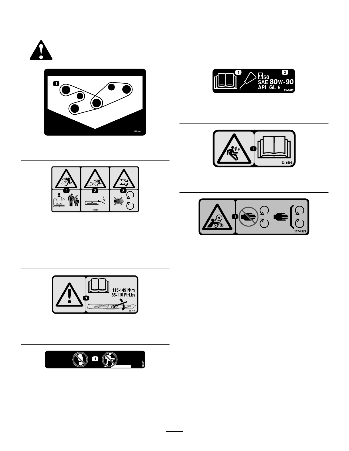
SafetyandInstructional
Decals
Safetydecalsandinstructionsareeasilyvisibletotheoperatorandarelocatednearanyareaofpotential
danger.Replaceanydecalthatisdamagedorlost.
93-6697
112-1461
1.Beltrouting
107-2908
1.Thrownobjecthazard—keepbystandersasafedistance
fromthemachine.
2.Thrownobjecthazard—donotoperatethemowerwiththe
deectoruporremoved,keepthedeectorinplace.
3.Cutting/dismembermenthazardofhandorfoot,mower
blade—stayawayfrommovingparts.
1.ReadtheOperator's
Manual.
1.Storedenergyhazard—readtheOperator'sManual.
1.Entanglementhazard,belt—stayawayfrommovingparts,
keepallguardsandshieldsinplace.
2.AddSAE80w-90(API
GL-5)oilevery50hours.
93–6696
117–4979
93-7818
1.Warning—readtheOperator'sManualforinstructionson
torquingthebladebolt/nutto115-149N-m(85-110ft-lb).
93-6687
1.Donotstephere.
5
Page 6
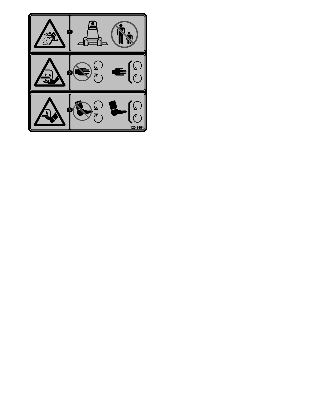
120-6604
1.Thrownobjecthazard—keepbystandersawayfromthe
machine.
2.Cutting/dismembermenthazardofhand,mower
blade—stayawayfrommovingparts,keepallguardsand
shieldsinplace.
3.Cutting/dismembermenthazardoffoot,mowerblade—stay
awayfrommovingparts,keepallguardsandshieldsin
place.
6
Page 7
Setup
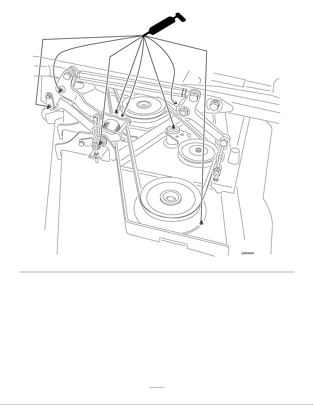
g017279
1
2
3
4
5
6
7
1
2
G017278
MediaandAdditionalParts
Description
Partscatalog1
Operator'sManual
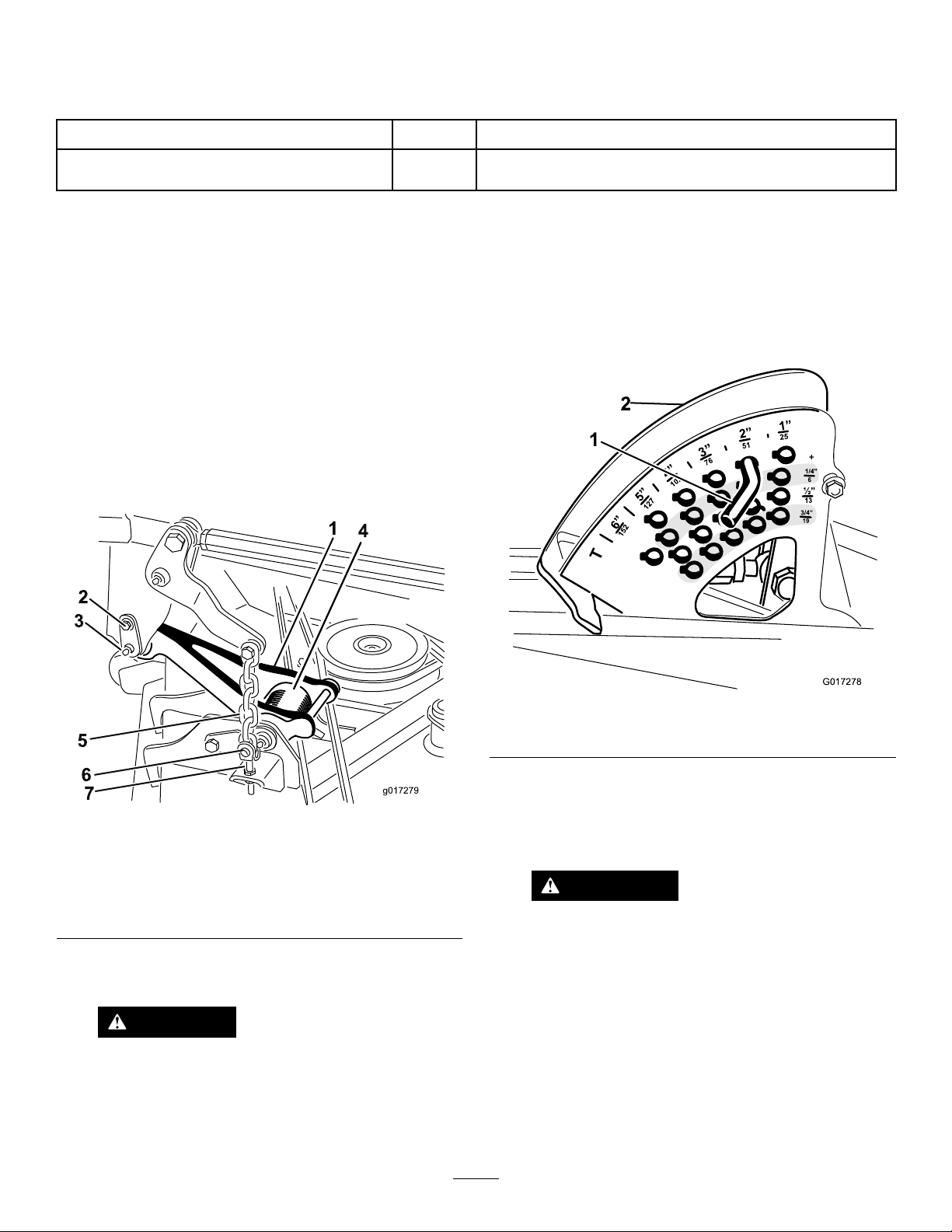
Note:Determinetheleftandrightsidesofthemachine
fromthenormaloperatingposition.
RemovingtheExistingMower
(ifapplicable)
1.Parkthemachineonalevelsurfacewiththemowerin
thefullyraisedposition.Stoptheengine,engagethe
parkingbrakeandremovethekeyfromtheignition
switch.
Note:Whenthemowerisintheraisedposition,the
pulllinktorsionspringtension(Figure2)isreduced
makingitmucheasiertodisconnectthepulllinksfrom
themachine.
Qty.
Use
1
Reviewthematerialandsaveinanappropriateplace:
A.Removetheshoulderscrewthatsecuresthe
retainerpintothecarrierframe(Figure2).
B.Carefullyslidetheretainerpinfromthecarrier
frameandthepulllink(Figure2).
3.NotethelocationoftheHOCpinintheHOCbracket
forassemblypurposes(Figure3).RemovetheHOC
pinfromtheHOCbracket.
Figure3
1.HOCpin2.HOCbracket
4.Starttheengineandfullylowerthemower.Stopthe
engineandremovethekeyfromtheignitionswitch.
Figure2
1.Pulllink(mowerraised)5.Mowerliftchain
2.Shoulderscrew6.Clevispin
3.Retainerpin7.Adjustmentclevis
4.T orsionspring
2.Disconnectthepulllinkfromeachsideofthemachine
(Figure2).
Note:Loweringthemowerontofurnituredollieswill
easetheremovalofthemower.
WARNING
Donotstarttheengineandengagethe
PTOswitchwhenthePTOdriveshaftis
disconnectedfromthemower.Iftheengine
isstartedandthePTOshaftisallowedto
rotate,seriouspersonalinjuryandmachine
CAUTION
Becarefulwhendisconnectingthepulllinks.
Thepulllinktorsionspringsmaycausesome
damagecouldresult.IfthePTOdriveshaftis
disconnectedfromthemower,removethefuse
F1(15amp)fromthefuseblocktoprevent
unintentionalengagementofthePTOclutch.
rotationofthepulllinksduringtheremoval
process.
5.DisconnecttheendyokeofthePTOdriveshaftfrom
themowergearboxshaft:
7
Page 8
A.Removetherollpinfromtheendyokeandthe
gearboxshaft(Figure4).
CAUTION
Becarefulwhenconnectingthepulllinksto
themachine.Thepulllinktorsionsprings
maycausesomerotationofthepulllinks
duringinstallation.
5.Alignthepulllinktothecarrierframeandattachthe
linkwiththeretainerpin(Figure2).Securetheretainer
pintotheframewiththeshoulderscrew(Figure2).
6.InstalltheHOCpinintotheHOCbracketatthe
desiredheightofcut(Figure3).
7.LubricatethePTOdriveshaftgreasettings.
Figure4
1.Driveshaft
2.Capscrewsandlocknuts4.Gearbox
B.Loosenthe(2)capscrewsandlocknuts(Figure4).
C.Slidethedriveshaftendyokefromthegearbox
shaft.
Note:Raiseandtiethedriveshafttotheframe.
6.Removethe(4)ringpinsandclevispinsthatsecure
theliftchainstotheadjustmentclevisesonthemower
(Figure2).
7.Slidethemowerawayfromthemachine.
Note:Thefrontofthetractionunitmayhaveto
elevatedtomovethemowerawayfromthemachine.
3.Rollpin
InstallingtheNewMower
1.Slidethenewmowerunderthecarrierframeofthe
machine.
2.Installthe(4)clevispinsandringpinstosecurethe
mowerliftchainstotheadjustmentclevisesonthe
mower(Figure2).
3.ConnecttheendyokeofthePTOdriveshafttothe
mowergearbox:
A.Alignthesplineandrollpinholesofthedrive
shaftyokewiththegearboxshaft.
B.SlidethePTOdriveshaftendyokeontothe
gearboxshaft.
C.SecuretheendyokeofthePTOdriveshafttothe
gearboxshaftwiththerollpin(Figure4).
D.Tightenthelocknutstosecuretheendyoketothe
gearboxshaft(Figure4).Torquethelocknutsto
20to25N-m(175to225in-lb).
4.Starttheengineandfullyraisethemower.Stopthe
engineandremovethekeyfromtheignitionswitch.
8.InstallthefuseF1(15amp)intothefuseblock.
LevelingtheMower
LevelingSidetoSide
1.Positionthemachineonalevelsurfaceontheshop
oor.
2.MovethethrottlelevertotheSlowposition,stopthe
engine,settheparkingbrake,andremovetheignition
key.
3.Setthemowertothe127mm(5inch)heightofcut
setting.
4.Checkandadjustfrontandreartractionunittire
pressure;refertoOperator’sManualforspecications.
5.Checkforbentblades;RefertoCheckingforBent
Blades.
6.Rotatethebladeoneachspindleuntiltheendsface
forwardandbackward.
7.Measurefromtheoortothefronttipofthecutting
edge.
8.Adjustthejamnutssecuringthemoweryokes/chains
tothemoweruntilthemowerislevel(Figure5).
Note:Placeawoodblockorsimilarshimundereach
linktoholditintheraisedposition.
8
Page 9

Figure5
Operation
Note:Determinetheleftandrightsidesofthemachine
fromthenormaloperatingposition.
Adjustments
AdjustingtheHeight-of-Cut
Theheight-of-cutisadjustedfrom2.5to15.8cm(1to
6inches)in6mm(1/4inch)incrementsbyrelocatingthe
stoppinintodifferentholelocations.
1.Withtheenginerunning,pushbackonthemowerlift
switchuntilthemowerisfullyraisedandreleasethe
switchimmediately(Figure6).
1.Chain
2.Y oke4.Mower
3.Jamnut
LevelingFronttoBack
Cuttingunitpitchisthedifferenceinheight-of-cutfromthe
frontofthebladeplanetothebackofthebladeplane.Toro
recommendsabladepitchofapproximately8to11mm
(5/16to7/16inch).Thatisthebackofthebladeplaneis8
to11mm(5/16to7/16inch)higherthanthefront.
1.Positionthemachineonalevelsurfaceontheshop
oor.
2.Setthemowertothedesiredheight-of-cut,movethe
throttlelevertotheSlowposition,stoptheengine,set
theparkingbrake,andremovetheignitionkey.
3.Rotatethecenterbladesothatitpointsstraight
forward.
4.Usingashortruler,measurefromtheoortothefront
tipoftheblade.
5.Rotatethesamebladetiptotherearandmeasurefrom
theoortothetipofthebladeattherearofthemower.
6.Subtractthefrontdimensionfromthereardimension
tocalculatethebladepitch.
7.Adjustthejamnutssecuringtherearmower
yokes/chains(Figure5)toraisetherearofthemower
sothatthebladepitchissetto8to11mm(5/16to
7/16inch).
Figure6
1.Stoppin
2.Toadjust,rotatethestoppinuntilthenubonitlinesup
withtheslotsintheholesintheheight-of-cutbracket
andremoveit(Figure6).
3.Selectaholeintheheight-of-cutbracketcorresponding
totheheight-of-cutdesired,insertthepin,androtateit
downtolockitinplace(Figure6).
Note:Therearefourrowsofholepositions(Figure
6).Thetoprowgivesyoutheheightofcutlistedabove
thepin.Thesecondrowdowngivesyoutheheight
listedplus6mm(1/4inch).Thethirdrowdown
givesyoutheheightlistedplus12mm(1/2inch).The
bottomrowgivesyoutheheightlistedplus18mm
(3/4inch).Forthe15.8cm(6inch)positionthereis
onlyonehole,locatedinthesecondrow .Thisdoesnot
add6mm(1/4inch)tothe15.8cm(6inch)position.
4.Adjusttheanti-scalprollersandskidsasrequired.
9
Page 10

AdjustingtheSkid(s)
Mounttheskidsinthelowerpositionwhenoperatingin
heightofcutshigherthan64mm(2-1/2inches)andinthe
higherpositionwhenoperatinginheightofcutslowerthan
64mm(2-1/2inches).
Note:OnGuardian
youcanswitchtheskidtotheoppositesidesofthemower,
ippingthemover.Thiswillallowyoutousetheskidslonger
beforereplacingthem.
1.DisengagethePTOandsettheparkingbrake.
2.MovethethrottlelevertotheSlowposition,stopthe
engine,removethekey,andwaitforallmovingpartsto
stopbeforeleavingtheoperatingposition.
3.Loosenthescrewatthefrontofeachskid.Thereare2
skidsonGuardianmowersand1skidonside-discharge
mowers(Figure7).
®
mowers,whentheskidsbecomeworn,
3.Afteradjustingtheheight-of-cut,adjusttherollersby
removingtheangenut,bushing,spacer,andbolt
(Figure8).
Figure8
Figure7
1.Screw3.Skid
2.Flange-headbolt4.Nut
4.Removetheange-headboltsandnutsfromeachskid.
5.Moveeachskidtothedesiredpositionandsecurethem
withtheange-headboltsandnuts.
Note:Onlyusethetoporcentersetsofholestoadjust
theskids.Thebottomholesareusedwhenswitching
sidesonaGuardianmower,atwhichtimetheybecome
thetopholesontheothersideofthemower.
6.Torquethescrewatthefrontofeachskidto9to11
N-m(80to100in-lb).
AdjustingtheRearAnti-ScalpRollers
Wheneveryouchangetheheight-of-cut,adjusttheheight
oftherearanti-scalprollers.
1.DisengagethePTO,releasethetractionpedal,andset
theparkingbrake.
2.MovethethrottlelevertotheSlowposition,stopthe
engine,removethekey,andwaitforallmovingpartsto
stopbeforeleavingtheoperatingposition.
1.Flangenut
2.Bushing5.Bolt
3.Anti-scalproller
4.Spacer
4.Selectaholesotheanti-scalprollerispositionedtothe
nearestcorrespondingheight-of-cutdesired(Figure9).
Figure9
1.38mm(1-1/2inches)3.63mm(2-1/2inches)
2.51mm(2inches)4.76mm(3inches)and
higher
5.Installtheangenutbushing,spacer,andbolt.Torque
to54-61N-m(40-45ft-lb)(Figure8).
AdjustingtheRollers
Mounttherollersinthelowerpositionwhenoperatingin
heightofcutshigherthan64mm(2-1/2inches)andinthe
higherpositionwhenoperatinginheightofcutslowerthan
64mm(2-1/2inches).
1.DisengagethePTO,releasethetractionpedalandset
theparkingbrake.
10
Page 11

2.MovethethrottlelevertotheSlowposition,stopthe
engine,removethekey,andwaitforallmovingpartsto
stopbeforeleavingtheoperatingposition.
3.Raisethefrontofthemachineandsupportitonjack
stands.
4.Removethefastenerssecuringeachrolleronyour
mowerandmovetherollersupordownasdesired;
refertoFigure10throughFigure14asapplicablefor
yourmower.
Figure12
GuardianMowerOnly
1.Bolt3.Nut
2.Frontunder-mowerroller4.Bracket
Figure10
AllMowers
1.Frontroller
Figure11
GuardianMowersOnly
1.Bolt4.Nut
2.Rearunder-mowerroller5.Bracket
3.Spacer
2.Rollershaft
Figure13
Side-dischargeMowersOnly
1.Bolt4.Nut
2.Chute-sideroller
3.Spacer
5.Bracket
11
Page 12

densegrass,youmayhavetoslowdowntheforwardspeed
and/orraisetheheight-of-cuttothenexthighersetting.
Important:Ifcuttingmorethan1/3ofthegrassblade
off,orinsparselonggrassordryconditions,theuse
ofatsailbladesisrecommendedtoreduceair-borne
chaff,debris,anddeckdrivecomponentstrain.
LongGrass
Ifthegrassiseverallowedtogrowslightlylongerthan
normal,orifitcontainsahighdegreeofmoisture,raisethe
cuttingheighthigherthanusualandcutthegrassatthis
setting.Thencutthegrassagainusingthelower,normal
setting.
Figure14
Side-dischargeMowersOnly
1.Bolt
2.Rollershaft
5.Installthefastenersasillustrated.
3.Under-mowerroller(2)
4.Bracket
OperatingTips
FastThrottleSetting/GroundSpeed
Tomaintainenoughpowerforthemachineanddeckwhile
mowing,operatetheengineatthefastthrottlepositionand
adjustyourgroundspeedforconditions.Agoodruleto
followis:decreasegroundspeedastheloadonthecutting
bladesincreases;andincreasegroundspeedasloadonthe
bladesdecreases.
MowingDirection
Alternatemowingdirectiontoavoidmakingrutsintheturf
overtime.Thisalsohelpsdisperseclippingswhichenhances
decompositionandfertilization.
KeeptheMowerClean
Cleanclippingsanddirtfromtheundersideofthemower
aftereachuse.Ifgrassanddirtbuildupinsidethemower,
cuttingqualitywilleventuallybecomeunsatisfactory.
Toreducetheriskofrehazard,keeptheengine,mufer,
batterycompartment,parkingbrake,cuttingunits,andfuel
storagecompartmentfreeofgrass,leaves,orexcessivegrease.
Cleanupanyspilledoilorfuel.
BladeMaintenance
Maintainasharpbladethroughoutthecuttingseasonbecause
asharpbladecutscleanlywithouttearingorshreddingthe
grassblades.Tearingandshreddingturnsgrassbrownat
theedges,whichslowsgrowthandincreasesthechanceof
disease.Checkthebladesdailyforsharpness,andforany
wearordamage.Sharpenthebladesasnecessary.Ifabladeis
damagedorworn,replaceitimmediatelywithagenuineToro
replacementblade.RefertoServicingtheCuttingBlades.
CuttingSpeed
Toimprovecutquality,useaslowergroundspeed.
AvoidCuttingTooLow
Ifthecuttingwidthofthemoweriswiderthanthemower
youpreviouslyused,raisethecuttingheighttoensurethat
uneventurfisnotcuttooshort.
SelecttheProperHeight-of-CutSetting
toSuitConditions
Removeapproximately1inch(25mm)ornomorethan1/3
ofthegrassbladewhencutting.Inexceptionallylushand
12
Page 13

Maintenance
Note:Determinetheleftandrightsidesofthemachinefromthenormaloperatingposition.
WARNING
Ifyouraisethemachineusingonlyajacktosupport
itwhileyouworkunderthemowerdeck,thejack
couldtip,causingthemowerdecktofall,crushing
youorbystanders.
Alwayssecurethemachinewithatleast2jack
standswhenyouhavethemowerdeckraised.
CAUTION
Onthetopofthemowerdeckaretwolinksthat
connectthemtotheframe.Connectedtotheselinks
aretorsionspringthatareundertension(Figure
15).Ifyoudisconnectthelinkthestoredenergyin
thetorsionspringwillbereleasedandcouldcause
thelinkstomove,damagingyourhandsorngers.
Becarefulwhenremovingthemowerdeckfrom
theframeandsecurethelinksbeforedisconnecting
themfromtheframe.
Figure15
1.Link2.T orsionspring
13
Page 14

RecommendedMaintenanceSchedule(s)
MaintenanceService
Interval
Aftertherst50hours
Beforeeachuseordaily
Every50hours
MaintenanceProcedure
•Checktheconditionofthebladedrivebeltsonthemower.
•Checkthemowerblades.
•Cleanthemower.
•Greasethebearingandbushinggreasettings.
DailyMaintenanceChecklist
Duplicatethispageforroutineuse.
Fortheweekof: MaintenanceCheckItem
Mon.Tues.Wed.Thurs.Fri.
CheckSafetyInterlock
Operation
CheckGrassDeectorin
DownPosition(ifapplicable)
CheckParkingBrake
Operation
CheckFuelLevel
CheckTirePressure
CheckInstrumentOperation
CheckConditionofBlades
LubricateAllGreaseFittings
Touch-upDamagedPaint
1.Immediatelyaftereverywashing,regardlessoftheintervallisted.
1
Sat.Sun.
NotationforAreasofConcern
Inspectionperformedby:
ItemDate
Information
CAUTION
Ifyouleavethekeyintheignitionswitch,someonecouldaccidentlystarttheengineandseriouslyinjure
youorotherbystanders.
Removethekeyfromtheignitionbeforeyoudoanymaintenance.
14
Page 15

Lubrication
GreasingtheBearingsandBushings
ServiceInterval:Every50hours
Themachinehasgreasettingsthatmustbelubricated
regularlywithNo.2GeneralPurposeLithiumBaseGrease.
Ifthemachineisoperatedundernormalconditions,lubricate
allbearingsandbushingsafterevery50hoursofoperation.
Bearingsandbushingsmustbelubricateddailywhen
operatingconditionsareextremelydustyanddirty.Dusty
anddirtyoperatingconditionscouldcausedirttogetinto
thebearingsandbushings,resultinginacceleratedwear.
Lubricatethegreasettingsimmediatelyaftereverywashing,
regardlessofintervalspecied.
1.Wipethegreasettingscleansoforeignmattercannot
beforcedintothebearingorbushing.
2.Pumpgreaseintothettings.
3.Wipeoffexcessgrease.
Figure16
15
Page 16
Note:Bearinglifecanbenegativelyaffectedbyimproper
washdownprocedures.Donotwashdowntheunitwhenit
isstillhotandavoiddirectinghigh-pressureorhighvolume
sprayatthebearingsorseals.
Figure17
16
Page 17

ReplacingtheBladeDrive
DANGER
Belts
ServiceInterval:Aftertherst50hours
Thebladedrivebelts,tensionedbythespringloadedidler
pulleys,areverydurable.However,aftermanyhoursofuse,
thebeltswillshowsignsofwear.Signsofawornbeltare:
squealingwhenbeltisrotating,bladesslippingwhencutting
grass,poorqualityofcut,frayededges,burnmarksand
cracks.Replacethebeltsifanyoftheseconditionsareevident.
1.Lowerthecuttingunittothe1inchheightofcut
setting,movethethrottlelevertotheSlowposition,
stoptheengine,settheparkingbrake,andremovethe
ignitionkey .
2.Removethebeltcoversfromthetopofthecuttingunit
andsetthecoversaside.
3.Usingabreakerbarorsimilartool,movetheidler
pulleyforthetopbelt(Figure18)awayfromthetop
drivebelttoreleasethebelttensionandallowthebelt
tobeslippedoffthepulleys.
Awornordamagedbladecanbreak,andapiece
ofthebladecouldbethrownintotheoperator's
orbystander'sarea,resultinginseriouspersonal
injuryordeath.
•Inspectthebladeperiodicallyforwearor
damage.
•Replaceawornordamagedblade.
Inspectandcheckthebladesevery8hours.
BeforeInspectingorServicingthe
Blades
1.DisengagethePTO,releasethetractionpedalandset
theparkingbrake.
2.MovethethrottlelevertotheSlowposition,stopthe
engine,removethekey,andwaitforallmovingpartsto
stopbeforeleavingtheoperatingposition.
InspectingtheBlades
ServiceInterval:Beforeeachuseordaily
Figure18
1.T opbelt3.Bottombelt
2.T opidlerpulley4.Bottomidlerpulley
4.Routeanewbeltaroundthegearboxpulley,bottom
spindlepulleys,andidlerpulleyassemblyasshownin
Figure18.
5.Routeanewbeltaroundthetopspindlepulleysand
idlerpulleyassemblyasshowninFigure18.
6.Greaseallmowerandmowerdrivegreasepoints.
7.Installthebeltcovers.
ServicingtheCuttingBlades
Maintainsharpbladesthroughoutthecuttingseasonbecause
sharpbladescutcleanlywithouttearingorshreddingthegrass
blades.Tearingandshreddingturnsgrassbrownattheedges,
whichslowsgrowthandincreasesthechanceofdisease.
1.Inspectthecuttingedges(Figure19).Iftheedges
arenotsharporhavenicks,removeandsharpenthe
blades.RefertoSharpeningtheBlades.
2.Inspecttheblades,especiallythesailarea(Figure19).
Ifyounoticeanydamage,wear,oraslotformingin
thisarea(Figure19),immediatelyinstallanewblade.
DANGER
Ifyouallowthebladetowear,aslotwillform
betweenthesailandatpartoftheblade.
Eventuallyapieceoftheblademaybreak
offandbethrownfromunderthehousing,
possiblyresultinginseriousinjurytoyouor
bystanders.
•Inspectthebladeperiodicallyforwearor
damage.
•Nevertrytostraightenabladethatisbent
orweldabrokenorcrackedblade.
•Replaceawornordamagedblade.
Checkthebladesdailyforsharpness,andforanywear
ordamage.Sharpenthebladesasnecessary.Ifabladeis
damagedorworn,replaceitimmediatelywithagenuineToro
replacementblade.
17
Page 18

Figure20
Figure19
1.CuttingEdge3.Wear/slotForming
2.SailArea4.Crack
CheckingforBentBlades
1.DisengagethePTO,releasethetractionpedalandset
theparkingbrake.
2.MovethethrottlelevertotheSlowposition,stopthe
engine,removethekey,andwaitforallmovingpartsto
stopbeforeleavingtheoperatingposition.
3.Rotatethebladesuntiltheendsfaceforwardand
backward(Figure20).Measurefromalevelsurfaceto
thecuttingedge,positionA,oftheblades(Figure20).
Notethisdimension.
1.Measureherefromblade
tohardsurface
4.Rotatetheoppositeendsofthebladesforward.
5.Measurefromalevelsurfacetothecuttingedgeof
thebladesatthesamepositionasinstep3above.
Thedifferencebetweenthedimensionsobtainedin
steps3and4mustnotexceed3mm(1/8inch).Ifthis
dimensionexceeds3mm(1/8inch),thebladeisbent
andmustbereplaced;refertoRemovingtheBlades
andInstallingtheBlades.
2.PositionA
WARNING
Abladethatisbentordamagedcouldbreak
apartandcouldseriouslyinjureorkillyouor
bystanders.
•Alwaysreplacebentordamagedblade
withanewblade.
•Neverleorcreatesharpnotchesinthe
edgesorsurfacesofblade.
RemovingtheBlades
Bladesmustbereplacedifasolidobjectishit,ifthebladeis
outofbalanceorisbent.Toensureoptimumperformance
andcontinuedsafetyconformanceofthemachine,use
genuineT ororeplacementblades.Replacementbladesmade
byothermanufacturersmayresultinnon-conformancewith
safetystandards.
WARNING
Contactwithasharpbladecancauseseriousinjury.
Wearglovesorwrapsharpedgesofthebladewith
arag.
1.Holdthebladeendusingaragorthickly-paddedglove.
18
Page 19

2.Removethebladebolt,anti-scalpplate,andbladefrom
thespindleshaft(Figure23).
SharpeningtheBlades
WARNING
Whensharpeningblade,piecesofbladecouldbe
thrownandcauseseriousinjury.
Wearpropereyeprotectionwhensharpening
blades.
1.Sharpenthecuttingedgeatbothendsoftheblade
(Figure21).Maintaintheoriginalangle.Theblade
retainsitsbalanceifthesameamountofmaterialis
removedfrombothcuttingedges.
Figure21
1.Sharpenatoriginalangle
2.Checkthebalanceofthebladebyputtingitonablade
balancer(Figure22).Ifthebladestaysinahorizontal
position,thebladeisbalancedandcanbeused.Ifthe
bladeisnotbalanced,lesomemetalofftheendof
thesailareaonly(Figure23).Repeatthisprocedure
untilthebladeisbalanced.
Figure22
1.Blade2.Balancer
InstallingtheBlades
1.Installthebladeontothespindleshaft(Figure23).
Important:Thecurvedpartoftheblademustbe
pointingupwardtowardtheinsideofthemowerto
ensurepropercutting.
2.Installtheanti-scalpplateandbladebolt(Figure23).
Figure23
1.Spindle
2.SailAreaofBlade
3.Torquethebladeboltto115-150N⋅m(85-110ft-lb).
3.Anti-scalpplate
4.BladeBolt
CorrectingMowerMismatch
Ifthecutisunevenacrossthemowerswath,correctitas
follows:
1.Positionthemachineonalevelsurfaceontheshop
oor.
2.Setthecuttingunittothedesiredheightofcut,move
thethrottlelevertotheSlowposition,stoptheengine,
settheparkingbrake,andremovetheignitionkey.
3.Checkandadjustfrontandreartractortirepressure;
refertoCheckingTirePressure.
4.Checkforbentblades.
5.Removethecoversfromthetopofthecuttingunits.
6.Rotatethebladeoneachspindleuntiltheendsface
forwardandbackward.
7.Measurefromtheoortothefronttipofthecutting
edge.
8.Adjustthejamnutssecuringthemoweryokes/chains
tothemoweruntilthemowerislevel(Figure24).
19
Page 20

Figure24
1.Frontmoweryokechain4.Y oke
2.Rearmoweryokechain5.Jamnut
3.Chain
6.Mower
AdjustingtheMowerPitch
ReplacingtheGrassDeector
WARNING
Anuncovereddischargeopeningcouldallowthe
machinetothrowobjectsintheoperator'sor
bystander'sdirectionandresultinseriousinjury.
Also,contactwiththebladecouldoccur.
•Neveroperatethemachinewithoutamulchkit
orgrassdeectorinstalled.
•Makesurethegrassdeectorisinthedown
position.
1.Lowerthecuttingunittotheshopoor,movethe
throttlelevertotheSlowposition,stoptheengine,set
theparkingbrake,andremovetheignitionkey.
2.Removethelocknut,bolt,springandspacerholding
thedeectortothepivotbrackets(Figure25).Remove
damagedorworngrassdeector.
Cuttingunitpitchisthedifferenceinheight-of-cutfromthe
frontofthebladeplanetothebackofthebladeplane.Toro
recommendsabladepitchofapproximately8mm(5/16
inch).Thatisthebackofthebladeplaneis8mm(5/16inch)
higherthanthefront.
1.Positionthemachineonalevelsurfaceontheshop
oor.
2.Setthecuttingunittothedesiredheight-of-cut,move
thethrottlelevertotheSlowposition,stoptheengine,
settheparkingbrake,andremovetheignitionkey.
3.Rotatethecenterbladesothatitpointsstraight
forward.
4.Usingashortruler,measurefromtheoortothefront
tipoftheblade.
5.Rotatethesamebladetiptotherearandmeasurefrom
theoortothetipofthebladeattherearofthemower.
6.Subtractthefrontdimensionfromthereardimension
tocalculatethebladepitch.
7.Adjustthejamnutssecuringtherearmower
yokes/chainstoraisetherearofthemowersothatthe
bladepitchissetto8mm(5/16inch)(Figure24).
Figure25
1.Bolt
2.Spacer6.GrassDeector
3.Locknut
4.Spring8.Righthandhookendof
5.Springinstalled
7.Lefthandhookendof
spring,placebehind
moweredgebefore
installingbolt
spring
3.Placethespacerandspringbetweenthereplacement
grassdeectorbrackets(Figure25).Placethelefthand
Jhookendofthespringbehindthemoweredge.
Note:MakesurethelefthandJhookendofthe
springisinstalledbehindthemoweredgebefore
installingtheboltasshowninFigure25.
4.Installtheboltandnut.PlacetherighthandJhookend
ofthespringaroundthegrassdeector(Figure25).
Important:Thegrassdeectormustbeableto
lowerdownintoposition.Liftthedeectorupto
testthatitlowersintothefulldownposition.
20
Page 21

CleaningUndertheMower
ServiceInterval:Beforeeachuseordaily
Removethegrassbuildupunderthemowerdaily.
Storage
1.Thoroughlycleanthemower,payingspecialattention
totheseareas:
1.DisengagethePTO,releasethetractionpedaltothe
neutralpositionandsettheparkingbrake.
2.MovethethrottlelevertotheSlowposition,stopthe
engine,removethekey,andwaitforallmovingpartsto
stopbeforeleavingtheoperatingposition.
3.Raisethemowertothetransportposition.
4.Raisethefrontofthemachinebyusingjackstands.
5.Thoroughlycleantheundersideofthemowerwith
water.
•Underneaththemower
•Underthemowerbeltcovers
•PTOshaftassembly
•Allgreasettingsandpivotpoints
2.Checkandadjustfrontandreartirepressure;referto
CheckingTirePressure.
3.Remove,sharpen,andbalancethemowerblades.
Installthebladesandtorquethebladefastenersto
85-110ft-lb(115-149N-m).
4.Checkallfastenersforloosenessandtightenthemas
necessary.
5.Greaseoroilallgreasettingsandpivotpoints.Wipe
offanyexcesslubricant.
6.Lightlysandandusetouchuppaintonpaintedareas
thatarescratched,chippedorrusted.Repairanydents.
21
Page 22

Notes:
22
Page 23

DeclarationofIncorporation
TheT oroCompany,8111LyndaleAve.South,Bloomington,MN,USAdeclaresthatthefollowingunit(s)
conform(s)tothedirectiveslisted,wheninstalledinaccordancewiththeaccompanyinginstructionsontocertain
ToromodelsasindicatedontherelevantDeclarationsofConformity.
ModelNo.
30353315000001andUp72inRotaryMower
30354315000001andUp
30456315000001andUp
30457315000001andUp62inRotaryMower
30481315000001andUp
SerialNo.
ProductDescriptionInvoiceDescription
GM7200/GM36072in
BASEDECK
72inSideDischargeMowerGM720072inSDDECKCE
60inSideDischargeMowerGM720060inSDDECK
GM720062inBASEDECK
72inSideDischargeMower72inS.D.DECK(NON)C.E.
GeneralDescription
72inRotaryMower
72inRotaryMower
60inRotaryMower
62inRotaryMower
72inRotaryMower
Directive
2006/42/EC,
2000/14/EC
2006/42/EC,
2000/14/EC
2006/42/EC,
2000/14/EC
2006/42/EC,
2000/14/EC
2006/42/EC,
2000/14/EC
RelevanttechnicaldocumentationhasbeencompiledasrequiredperPartBofAnnexVIIof2006/42/EC.
Wewillundertaketotransmit,inresponsetorequestsbynationalauthorities,relevantinformationonthispartly
completedmachinery.Themethodoftransmissionshallbeelectronictransmittal.
ThismachineryshallnotbeputintoserviceuntilincorporatedintoapprovedToromodelsasindicatedonthe
associatedDeclarationofConformityandinaccordancewithallinstructions,wherebyitcanbedeclaredin
conformitywithallrelevantDirectives.
Certied:EUTechnicalContact:
PeterT etteroo
ToroEuropeNV
B-2260Oevel-Westerloo
Belgium
DavidKlisTel.003214562960
Sr.EngineeringManager
811 1LyndaleAve.South
Bloomington,MN55420,USA
September26,2013
Fax003214581911
23
Page 24

ToroGeneralCommercialProductWarranty
ATwo-YearLimitedWarranty
ConditionsandProductsCovered
TheToroCompanyanditsafliate,ToroWarrantyCompany,pursuant
toanagreementbetweenthem,jointlywarrantyourT oroCommercial
product(“Product”)tobefreefromdefectsinmaterialsorworkmanship
fortwoyearsor1500operationalhours*,whicheveroccursrst.This
warrantyisapplicabletoallproductswiththeexceptionofAerators
(refertoseparatewarrantystatementsfortheseproducts).Wherea
warrantableconditionexists,wewillrepairtheProductatnocosttoyou
includingdiagnostics,labor,parts,andtransportation.Thiswarranty
beginsonthedatetheProductisdeliveredtotheoriginalretailpurchaser.
*Productequippedwithanhourmeter.
InstructionsforObtainingWarrantyService
YouareresponsiblefornotifyingtheCommercialProductsDistributoror
AuthorizedCommercialProductsDealerfromwhomyoupurchasedthe
Productassoonasyoubelieveawarrantableconditionexists.Ifyouneed
helplocatingaCommercialProductsDistributororAuthorizedDealer,or
ifyouhavequestionsregardingyourwarrantyrightsorresponsibilities,
youmaycontactusat:
ToroCommercialProductsServiceDepartment
ToroWarrantyCompany
811 1LyndaleAvenueSouth
Bloomington,MN55420-1196
952–888–8801or800–952–2740
E-mail:commercial.warranty@toro.com
OwnerResponsibilities
AstheProductowner,youareresponsibleforrequiredmaintenanceand
adjustmentsstatedinyourOperator'sManual.Failuretoperformrequired
maintenanceandadjustmentscanbegroundsfordisallowingawarranty
claim.
ItemsandConditionsNotCovered
Notallproductfailuresormalfunctionsthatoccurduringthewarranty
periodaredefectsinmaterialsorworkmanship.Thiswarrantydoesnot
coverthefollowing:
•Productfailureswhichresultfromtheuseofnon-T ororeplacement
parts,orfrominstallationanduseofadd-on,ormodiednon-Toro
brandedaccessoriesandproducts.Aseparatewarrantymaybe
providedbythemanufactureroftheseitems.
•Productfailureswhichresultfromfailuretoperformrecommended
maintenanceand/oradjustments.Failuretoproperlymaintainyour
ToroproductpertheRecommendedMaintenancelistedinthe
Operator’sManualcanresultinclaimsforwarrantybeingdenied.
•ProductfailureswhichresultfromoperatingtheProductinanabusive,
negligent,orrecklessmanner.
•Partssubjecttoconsumptionthroughuseunlessfoundtobedefective.
Examplesofpartswhichareconsumed,orusedup,duringnormal
Productoperationinclude,butarenotlimitedto,brakepadsand
linings,clutchlinings,blades,reels,rollersandbearings(sealedor
greasable),bedknives,sparkplugs,castorwheelsandbearings,tires,
lters,belts,andcertainsprayercomponentssuchasdiaphragms,
nozzles,andcheckvalves,etc.
•Failurescausedbyoutsideinuence.Conditionsconsideredtobe
outsideinuenceinclude,butarenotlimitedto,weather,storage
practices,contamination,useofunapprovedfuels,coolants,lubricants,
additives,fertilizers,water,orchemicals,etc.
•Failureorperformanceissuesduetotheuseoffuels(e.g.gasoline,
diesel,orbiodiesel)thatdonotconformtotheirrespectiveindustry
standards.
•Normalnoise,vibration,wearandtear ,anddeterioration.
•Normal“wearandtear”includes,butisnotlimitedto,damagetoseats
duetowearorabrasion,wornpaintedsurfaces,scratcheddecalsor
windows,etc.
Parts
Partsscheduledforreplacementasrequiredmaintenancearewarranted
fortheperiodoftimeuptothescheduledreplacementtimeforthatpart.
Partsreplacedunderthiswarrantyarecoveredforthedurationofthe
originalproductwarrantyandbecomethepropertyofT oro.Torowillmake
thenaldecisionwhethertorepairanyexistingpartorassemblyorreplace
it.T oromayuseremanufacturedpartsforwarrantyrepairs.
DeepCycleandLithium-IonBatteryWarranty:
DeepcycleandLithium-Ionbatterieshaveaspeciedtotalnumberof
kilowatt-hourstheycandeliverduringtheirlifetime.Operating,recharging,
andmaintenancetechniquescanextendorreducetotalbatterylife.Asthe
batteriesinthisproductareconsumed,theamountofusefulworkbetween
chargingintervalswillslowlydecreaseuntilthebatteryiscompletelyworn
out.Replacementofwornoutbatteries,duetonormalconsumption,
istheresponsibilityoftheproductowner.Batteryreplacementmaybe
requiredduringthenormalproductwarrantyperiodatowner’sexpense.
Note:(Lithium-Ionbatteryonly):ALithium-Ionbatteryhasapartonly
proratedwarrantybeginningyear3throughyear5basedonthetime
inserviceandkilowatthoursused.RefertotheOperator'sManualfor
additionalinformation.
MaintenanceisatOwner’sExpense
Enginetune-up,lubrication,cleaningandpolishing,replacementoflters,
coolant,andcompletingrecommendedmaintenancearesomeofthe
normalservicesT oroproductsrequirethatareattheowner’sexpense.
GeneralConditions
RepairbyanAuthorizedToroDistributororDealerisyoursoleremedy
underthiswarranty.
NeitherTheToroCompanynorToroWarrantyCompanyisliablefor
indirect,incidentalorconsequentialdamagesinconnectionwiththe
useoftheToroProductscoveredbythiswarranty,includingany
costorexpenseofprovidingsubstituteequipmentorserviceduring
reasonableperiodsofmalfunctionornon-usependingcompletion
ofrepairsunderthiswarranty.ExceptfortheEmissionswarranty
referencedbelow,ifapplicable,thereisnootherexpresswarranty .All
impliedwarrantiesofmerchantabilityandtnessforusearelimitedto
thedurationofthisexpresswarranty.
Somestatesdonotallowexclusionsofincidentalorconsequential
damages,orlimitationsonhowlonganimpliedwarrantylasts,sotheabove
exclusionsandlimitationsmaynotapplytoyou.Thiswarrantygivesyou
speciclegalrights,andyoumayalsohaveotherrightswhichvaryfrom
statetostate.
Noteregardingenginewarranty:
TheEmissionsControlSystemonyourProductmaybecoveredby
aseparatewarrantymeetingrequirementsestablishedbytheU.S.
EnvironmentalProtectionAgency(EPA)and/ortheCaliforniaAirResources
Board(CARB).Thehourlimitationssetforthabovedonotapplytothe
EmissionsControlSystemWarranty.RefertotheEngineEmissionControl
WarrantyStatementsuppliedwithyourproductorcontainedintheengine
manufacturer’sdocumentationfordetails
CountriesOtherthantheUnitedStatesorCanada
CustomerswhohavepurchasedT oroproductsexportedfromtheUnitedStatesorCanadashouldcontacttheirT oroDistributor(Dealer)toobtain
guaranteepoliciesforyourcountry ,province,orstate.IfforanyreasonyouaredissatisedwithyourDistributor'sserviceorhavedifcultyobtaining
guaranteeinformation,contacttheT oroimporter.
374-0253RevC
 Loading...