

Page 1

72inRotaryMower
62inRotaryMower
60inRotaryMower
FormNo.3373-522RevA
Groundsmaster
®
360Seriesand7200Series
TractionUnit
ModelNo.30353—SerialNo.312000001andUp
ModelNo.30354—SerialNo.312000001andUp
ModelNo.30456—SerialNo.312000001andUp
ModelNo.30457—SerialNo.312000001andUp
ModelNo.30481—SerialNo.312000001andUp
ToregisteryourproductordownloadanOperator'sManualorPartsCatalogatnocharge,gotowww.T oro.com.OriginalInstructions(EN)
Page 2

Mowerswithmodelnumbers30353,30457and
30354complywithallrelevantEuropeandirectives,
fordetailspleaseseetheseparateproductspecic
Introduction
DeclarationofConformity(DOC)sheet.
Readthisinformationcarefullytolearnhowtooperate
andmaintainyourproductproperlyandtoavoidinjury
andproductdamage.Youareresponsibleforoperating
theproductproperlyandsafely.
YoumaycontactT orodirectlyatwww.Toro.comfor
productandaccessoryinformation,helpndingadealer,
ortoregisteryourproduct.
Wheneveryouneedservice,genuineToroparts,or
additionalinformation,contactanAuthorizedService
DealerorT oroCustomerServiceandhavethemodel
andserialnumbersofyourproductready .Writethe
numbersinthespaceprovided.
ModelNo.
SerialNo.
Thismanualidentiespotentialhazardsandhassafety
messagesidentiedbythesafetyalertsymbol(Figure1),
whichsignalsahazardthatmaycauseseriousinjury
ordeathifyoudonotfollowtherecommended
precautions.
Figure1
1.Safetyalertsymbol
Thismanualuses2otherwordstohighlightinformation.
Importantcallsattentiontospecialmechanical
informationandNoteemphasizesgeneralinformation
worthyofspecialattention.
Mowermodelnumber30456complieswithall
relevantEuropeandirectives,whentheCEKit,Part
No.117-9248isinstalledonthemower.Fordetails
pleaseseetheseparateproductspecicDeclaration
ofConformity(DOC)sheet.
Mowermodelnumber30481doesnotcomplywith
allrelevantEuropeandirectives.
Contents
Introduction.................................................................2
Safety...........................................................................3
SafeOperatingPractices.......................................3
ToroRidingMowerSafety....................................4
SafetyandInstructionalDecals.............................5
Setup...........................................................................7
RemovingtheExistingMower(if
applicable)........................................................7
InstallingtheNewMower....................................8
LevelingtheMower..............................................8
Operation.....................................................................9
Adjustments.........................................................9
OperatingTips...................................................13
Maintenance...............................................................14
RecommendedMaintenanceSchedule(s)................15
DailyMaintenanceChecklist...............................15
Lubrication.........................................................16
CheckingtheTirePressure.................................18
ReplacingtheBladeDriveBelts..........................18
ServicingtheCuttingBlades...............................18
CleaningUndertheMower.................................22
Storage.......................................................................22
©2012—TheToro®Company
8111LyndaleAvenueSouth
Bloomington,MN55420
Contactusatwww.Toro.com.
2
PrintedintheUSA.
AllRightsReserved
Page 3

Safety
–Storefuelincontainersspecicallydesignedfor
thispurpose.
SafeOperatingPractices
ThefollowinginstructionsarefromtheCENstandard
EN836:1997andANSIB71.4-2004.
Thisproductiscapableofamputatinghandsand
feetandthrowingobjects.Alwaysfollowallsafety
instructionstoavoidseriousinjuryordeath.
Training
•ReadtheOperator'sManualandothertrainingmaterial
carefully.Befamiliarwiththecontrols,safetysigns,
andtheproperuseoftheequipment.
•Neverallowchildrenorpeopleunfamiliarwiththese
instructionstousethisequipment.Localregulations
canrestricttheageoftheoperator.
•Neveroperatewhilepeople,especiallychildren,or
petsarenearby.
•Keepinmindthattheoperatororuserisresponsible
foraccidentsorhazardsoccurringtootherpeopleor
theirproperty.
•Donotcarrypassengers.
•Alldriversshouldseekandobtainprofessional
andpracticalinstruction.Suchinstructionshould
emphasize:
–theneedforcareandconcentrationwhen
workingwithride-onmachines;
–controlofaride-onmachineslidingonaslope
willnotberegainedbytheapplicationofthe
brake.Themainreasonsforlossofcontrolare:
◊insufcientwheelgrip,especiallyonwet
grass;
◊beingdriventoofast;
◊inadequatebraking;
◊thetypeofmachineisunsuitableforitstask;
◊lackofawarenessoftheeffectofground
conditions,especiallyslopes;
◊incorrectloaddistribution.
Preparation
•Whileoperatingthemachine,alwayswearsubstantial
footwearandlongtrousers.Donotoperatethe
equipmentwhenbarefootorwearingopensandals.
•Thoroughlyinspecttheareawheretheequipment
istobeusedandremoveallobjectswhichmaybe
thrownbythemachine.
•Warning—fuelishighlyammable.
–Refueloutdoorsonlyanddonotsmokewhile
refueling.
–Addfuelbeforestartingtheengine.Never
removethecapofthefueltankoraddfuelwhile
theengineisrunningorwhentheengineishot.
–Iffuelisspilled,donotattempttostartthe
enginebutmovethemachineawayfromthe
areaofspillageandavoidcreatinganysourceof
ignitionuntilfuelvaporshavedissipated.
–Replaceallfueltankandcontainercapssecurely.
•Replacefaultysilencers/mufers.
•Ifamowerisinstalledonthemachine,beforeusing
it,alwaysvisuallyinspecttoseethattheblades,blade
boltsandcutterassemblyarenotwornordamaged.
Replacewornordamagedbladesandboltsinsets
topreservebalance.
Operation
•Bealert,slowdownandusecautionwhenmaking
turns.Lookbehindandtothesidebeforechanging
directions.
•Donotoperatetheengineinaconnedspacewhere
dangerouscarbonmonoxidefumescancollect.
•Operateonlyindaylightoringoodarticiallight.
•Beforeattemptingtostarttheengine,disengageall
bladeattachmentclutchesandshiftintoneutral.
•Rememberthereisnosuchthingasasafeslope.
Travelongrassslopesrequiresparticularcare.To
guardagainstoverturning:
–donotstoporstartsuddenlywhenonaslope;
–useslowspeedsonslopesandduringtightturns;
–stayalertforhumpsandhollowsandother
hiddenhazards;
•Watchoutfortrafcwhencrossingornearroadways.
•Whenusinganyattachments,neverdirectdischarge
ofmaterialtowardbystandersnorallowanyonenear
themachinewhileinoperation.
•Neveroperatethemachinewithdamagedguards,
shields,orwithoutsafetyprotectivedevicesinplace.
•Donotchangetheenginegovernorsettingsor
overspeedtheengine.Operatingtheengineat
excessivespeedmayincreasethehazardofpersonal
injury.
•Beforeleavingtheoperator'sposition:
–disengagethepowertake-offandlowerthe
attachments;
3
Page 4

–settheparkingbrake;
–stoptheengineandremovethekey.
•Disengagedrivetoattachments,stoptheengine,and
removetheignitionkey:
–beforechecking,cleaningorworkingonthe
machine;
–afterstrikingaforeignobject.Inspectthe
machinefordamageandmakerepairsbefore
restartingandoperatingtheequipment;
–ifthemachinestartstovibrateabnormally(check
immediately).
•Donotoperatethemachineundertheinuenceof
alcoholordrugs.
•Lightningcancausesevereinjuryordeath.If
lightningisseenorthunderisheardinthearea,do
notoperatethemachine;seekshelter.
•Disengagedrivetoattachmentswhentransporting
ornotinuse.
•Stoptheengineanddisengagedrivetoattachment
beforerefueling.
•Keephands,feet,hairandlooseclothingawayfrom
attachmentdischargearea,undersideofmowerand
anymovingpartswhileengineisrunning.
•Donottouchequipmentorattachmentpartswhich
maybehotfromoperation.Allowtocoolbefore
attemptingtomaintain,adjust,orservice.
•Batteryacidispoisonousandcancauseburns.Avoid
contactwithskin,eyesandclothing.Protectyour
face,eyes,andclothingwhenworkingwithabattery.
•Thismachineisnotdesignedorequippedfor
on-roaduseandisa“slow-movingvehicle.”Ifyou
mustcrossortravelonapublicroad,youshould
beawareofandcomplywithlocalregulations,such
asrequiredlights,slowmovingvehiclesigns,and
reectors.
•Batterygasescanexplode.Keepcigarettes,sparks
andamesawayfrombattery.
•UseonlygenuineTororeplacementpartstoensure
thatoriginalstandardsaremaintained.
•UseonlyToroapprovedattachments.Warrantymay
bevoidedifusedwithunapprovedattachments.
MaintenanceandStorage
•Keepallnuts,boltsandscrewstighttobesurethe
equipmentisinsafeworkingcondition.
•Neverstoretheequipmentwithfuelinthetank
insideabuildingwherefumesmayreachanopen
ameorspark.
•Allowtheenginetocoolbeforestoringinany
enclosure.
•Toreducetherehazard,keeptheengine,
silencer/mufer,batterycompartmentandfuel
storageareafreeofgrass,leaves,orexcessivegrease.
•Replacewornordamagedpartsforsafety.
•Ifthefueltankhastobedrained,dothisoutdoors.
•Ifamowerisinstalledonthemachine,takecareas
manuallyrotatingonebladecancauseotherblades
torotate.
•Whenmachineistobeparked,storedorleft
unattended,lowertheattachment.
ToroRidingMowerSafety
Thefollowinglistcontainssafetyinformationspecicto
Toroproductsorothersafetyinformationthatyoumust
knowthatisnotincludedintheCENstandard.
SlopeOperation
•Donotoperateneardrop-offs,ditches,steepbanks
orwater.Wheelsdroppingoveredgescancause
rollovers,whichmayresultinseriousinjury,death,
ordrowning.
•Donotoperateonslopeswhengrassiswet.Slippery
conditionsreducetractionandcouldcausesliding
andlossofcontrol.
•Donotmakesuddenturnsorrapidspeedchanges.
•Reducespeedanduseextremecautiononslopes.
•Removeormarkobstaclessuchasrocks,treelimbs,
etc.fromtheoperatingarea.Tallgrasscanhide
obstacles.
•Watchforditches,holes,rocks,dips,andrisesthat
changetheoperatingangle,asroughterraincould
overturnthemachine.
•Avoidsuddenstartswhenoperatinguphillbecause
themachinemaytipbackwards.
•Alwaysavoidsuddenstartingorstoppingonaslope.
Iftireslosetraction,disengagetheattachmentand
proceedslowlyofftheslope.
•Followthemanufacturer'srecommendationsfor
wheelweightsorcounterweightstoimprovestability.
•Engineexhaustcontainscarbonmonoxide,whichis
anodorless,deadlypoisonthatcankillyou.Donot
runengineindoorsorinanenclosedarea.
•Useextremecarewithallattachments.Thesecan
changethestabilityofthemachineandcauseloss
ofcontrol.
4
Page 5
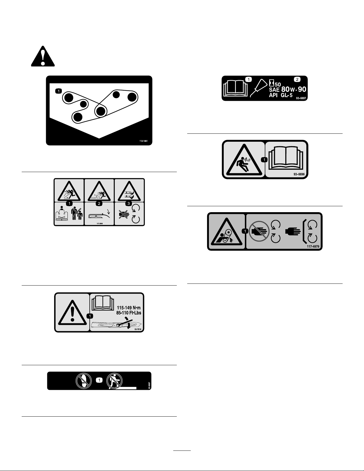
SafetyandInstructional
Decals
Safetydecalsandinstructionsareeasilyvisibletotheoperatorandarelocatednearanyareaof
potentialdanger.Replaceanydecalthatisdamagedorlost.
93-6697
112-1461
1.Beltrouting
107-2908
1.Thrownobjecthazard—keepbystandersasafedistance
fromthemachine.
2.Thrownobjecthazard—donotoperatethemowerwiththe
deectoruporremoved,keepthedeectorinplace.
3.Cutting/dismembermenthazardofhandorfoot,mower
blade—stayawayfrommovingparts.
1.ReadtheOperator's
Manual.
1.Storedenergyhazard—readtheOperator'sManual.
1.Entanglementhazard,belt—stayawayfrommovingparts,
keepallguardsandshieldsinplace.
2.AddSAE80w-90(API
GL-5)oilevery50hours.
93–6696
117–4979
93-7818
1.Warning—readtheOperator'sManualforinstructionson
torquingthebladebolt/nutto115-149N-m(85-110ft-lb).
93-6687
1.Donotstephere.
5
Page 6
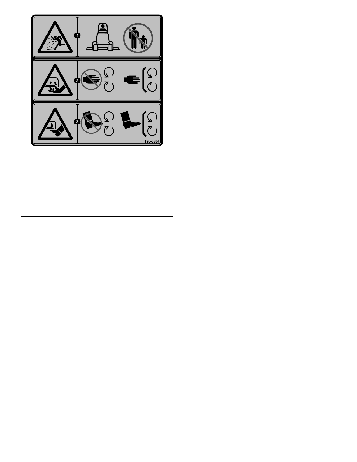
120-6604
1.Thrownobjecthazard—keepbystandersawayfromthe
machine.
2.Cutting/dismembermenthazardofhand,mower
blade—stayawayfrommovingparts,keepallguardsand
shieldsinplace.
3.Cutting/dismembermenthazardoffoot,mowerblade—stay
awayfrommovingparts,keepallguardsandshieldsin
place.
6
Page 7
Setup
g017279
1
2
3
4
5
6
7
1
2
G017278
MediaandAdditionalParts
Description
Partscatalog1
Operator'sManual
CerticateofCompliance
Note:Determinetheleftandrightsidesofthemachine
fromthenormaloperatingposition.
RemovingtheExistingMower
(ifapplicable)
1.Parkthemachineonalevelsurfacewiththemower
inthefullyraisedposition.Stoptheengine,engage
theparkingbrakeandremovethekeyfromthe
ignitionswitch.
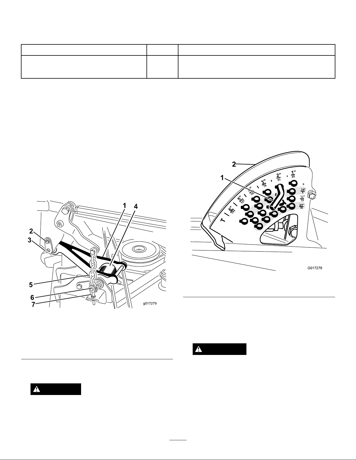
Note:Whenthemowerisintheraisedposition,the
pulllinktorsionspringtension(
makingitmucheasiertodisconnectthepulllinks
fromthemachine.
Figure2)isreduced
Qty.
Use
1
1
Reviewthematerialandsaveinanappropriateplace:
A.Removetheshoulderscrewthatsecuresthe
retainerpintothecarrierframe(
Figure2).
B.Carefullyslidetheretainerpinfromthecarrier
frameandthepulllink(Figure2).
3.NotethelocationoftheHOCpinintheHOC
bracketforassemblypurposes(
Figure3).Remove
theHOCpinfromtheHOCbracket.
Figure3
1.HOCpin2.HOCbracket
4.Starttheengineandfullylowerthemower.Stopthe
Figure2
1.Pulllink(mowerraised)5.Mowerliftchain
2.Shoulderscrew6.Clevispin
3.Retainerpin7.Adjustmentclevis
4.Torsionspring
2.Disconnectthepulllinkfromeachsideofthe
machine(Figure2).
CAUTION
Becarefulwhendisconnectingthepulllinks.
Thepulllinktorsionspringsmaycausesome
rotationofthepulllinksduringtheremoval
process.
engineandremovethekeyfromtheignitionswitch.
Note:Loweringthemowerontofurnituredollies
willeasetheremovalofthemower.
WARNING
DonotstarttheengineandengagethePTO
switchwhenthePTOdriveshaftisdisconnected
fromthemower.Iftheengineisstartedandthe
PTOshaftisallowedtorotate,seriouspersonal
injuryandmachinedamagecouldresult.If
thePTOdriveshaftisdisconnectedfromthe
mower,removethefuseF1(15amp)fromthe
fuseblocktopreventunintentionalengagement
ofthePTOclutch.
7
Page 8
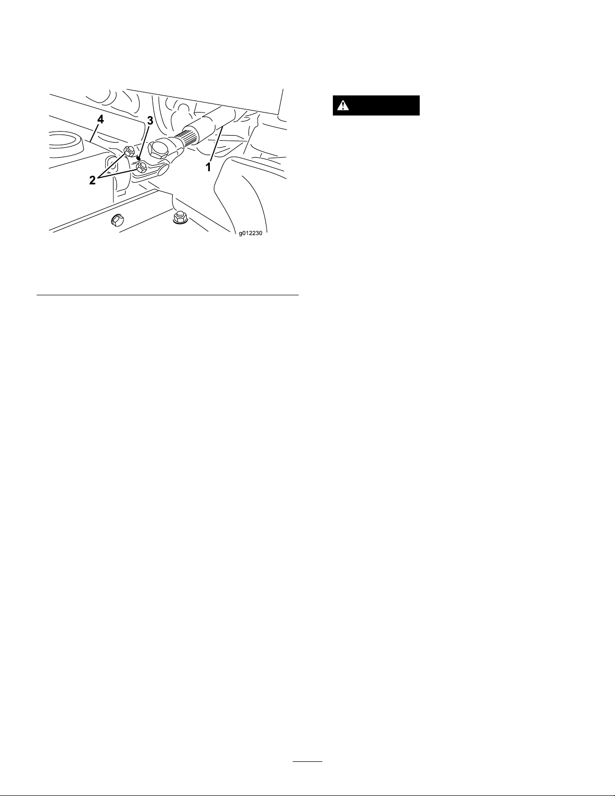
5.DisconnecttheendyokeofthePTOdriveshaft
fromthemowergearboxshaft:
4.Starttheengineandfullyraisethemower.Stopthe
engineandremovethekeyfromtheignitionswitch.
A.Removetherollpinfromtheendyokeandthe
gearboxshaft(Figure4).
Figure4
1.Driveshaft
2.Capscrewsandlocknuts4.Gearbox
B.Loosenthe(2)capscrewsandlocknuts(Figure4).
C.Slidethedriveshaftendyokefromthegearbox
shaft.
3.Rollpin
Note:Placeawoodblockorsimilarshimunder
eachlinktoholditintheraisedposition.
CAUTION
Becarefulwhenconnectingthepulllinksto
themachine.Thepulllinktorsionspringsmay
causesomerotationofthepulllinksduring
installation.
5.Alignthepulllinktothecarrierframeandattach
thelinkwiththeretainerpin(Figure2).Securethe
retainerpintotheframewiththeshoulderscrew
Figure2).
(
6.InstalltheHOCpinintotheHOCbracketatthe
desiredheightofcut(Figure3).
7.LubricatethePTOdriveshaftgreasettings.
8.InstallthefuseF1(15amp)intothefuseblock.
LevelingtheMower
Note:Raiseandtiethedriveshafttotheframe.
6.Removethe(4)ringpinsandclevispinsthatsecure
theliftchainstotheadjustmentclevisesonthe
mower(Figure2).
7.Slidethemowerawayfromthemachine.
Note:Thefrontofthetractionunitmayhaveto
elevatedtomovethemowerawayfromthemachine.
InstallingtheNewMower
1.Slidethenewmowerunderthecarrierframeofthe
machine.
2.Installthe(4)clevispinsandringpinstosecurethe
mowerliftchainstotheadjustmentclevisesonthe
mower(Figure2).
3.ConnecttheendyokeofthePTOdriveshafttothe
mowergearbox:
A.Alignthesplineandrollpinholesofthedrive
shaftyokewiththegearboxshaft.
B.SlidethePTOdriveshaftendyokeontothe
gearboxshaft.
LevelingSidetoSide
1.Positionthemachineonalevelsurfaceontheshop
oor.
2.MovethethrottlelevertotheSlowposition,stop
theengine,settheparkingbrake,andremovethe
ignitionkey.
3.Setthemowertothe5inch(127mm)heightofcut
setting.
4.Checkandadjustfrontandreartractionunit
tirepressure;refertoOperator’sManualfor
specications.
5.Checkforbentblades;RefertoCheckingforBent
Blades.
6.Rotatethebladeoneachspindleuntiltheendsface
forwardandbackward.
7.Measurefromtheoortothefronttipofthecutting
edge.
8.Adjustthejamnutssecuringthemoweryokes/chains
tothemoweruntilthemowerislevel(
Figure5).
C.SecuretheendyokeofthePTOdriveshaftto
thegearboxshaftwiththerollpin(Figure4).
D.Tightenthelocknutstosecuretheendyoketo
thegearboxshaft(Figure4).Torquethelocknuts
to175to225in-lb(20to25N-m)
8
Page 9

Figure5
1.Chain
2.Yoke4.Mower
3.Jamnut
LevelingFronttoBack
Cuttingunitpitchisthedifferenceinheight-of-cutfrom
thefrontofthebladeplanetothebackoftheblade
plane.T ororecommendsabladepitchofapproximately
5/16to7/16inch(8to11mm).Thatisthebackofthe
bladeplaneis5/16to7/16inch(8to11mm)higher
thanthefront.
Operation
Note:Determinetheleftandrightsidesofthe
machinefromthenormaloperatingposition.
Adjustments
AdjustingtheHeight-of-Cut
Theheight-of-cutisadjustedfrom1to6inches
(2.5to15.8cm)in1/4inch(6mm)incrementsby
relocatingthestoppinintodifferentholelocations.
1.Withtheenginerunning,pushbackonthemower
liftswitchuntilthemowerisfullyraisedandrelease
theswitchimmediately(
Figure6).
1.Positionthemachineonalevelsurfaceontheshop
oor.
2.Setthemowertothedesiredheight-of-cut,movethe
throttlelevertotheSlowposition,stoptheengine,
settheparkingbrake,andremovetheignitionkey .
3.Rotatethecenterbladesothatitpointsstraight
forward.
4.Usingashortruler,measurefromtheoortothe
fronttipoftheblade.
5.Rotatethesamebladetiptotherearandmeasure
fromtheoortothetipofthebladeattherearof
themower.
6.Subtractthefrontdimensionfromtherear
dimensiontocalculatethebladepitch.
7.Adjustthejamnutssecuringtherearmower
yokes/chains(
mowersothatthebladepitchissetto5/16to7/16
inch(8to11mm).
Figure5)toraisetherearofthe
Figure6
1.Stoppin
2.Toadjust,rotatethestoppinuntilthenubonitlines
upwiththeslotsintheholesintheheight-of-cut
bracketandremoveit(
3.Selectaholeintheheight-of-cutbracket
correspondingtotheheight-of-cutdesired,insert
thepin,androtateitdowntolockitinplace
(Figure6).
Note:Therearefourrowsofholepositions
Figure6).Thetoprowgivesyoutheheightofcut
(
listedabovethepin.Thesecondrowdowngives
youtheheightlistedplus1/4inch(6mm).The
thirdrowdowngivesyoutheheightlistedplus1/2
inch(12mm).Thebottomrowgivesyoutheheight
listedplus3/4inch(18mm).Forthe6inch(15.8
cm)positionthereisonlyonehole,locatedinthe
Figure6).
9
Page 10

secondrow .Thisdoesnotadd1/4inch(6mm)to
the6inch(15.8cm)position.
4.Adjusttheanti-scalprollersandskidsasrequired.
AdjustingtheRearAnti-ScalpRollers
Wheneveryouchangetheheight-of-cut,adjustthe
heightoftherearanti-scalprollers.
AdjustingtheSkid(s)
Mounttheskidsinthelowerpositionwhenoperating
inheightofcutshigherthan2-1/2inches(64mm)and
inthehigherpositionwhenoperatinginheightofcuts
lowerthan2-1/2inches(64mm).
Note:OnGuardian
worn,youcanswitchtheskidtotheoppositesidesof
themower,ippingthemover.Thiswillallowyouto
usetheskidslongerbeforereplacingthem.
1.DisengagethePTOandsettheparkingbrake.
2.MovethethrottlelevertotheSlowposition,stop
theengine,removethekey,andwaitforallmoving
partstostopbeforeleavingtheoperatingposition.
3.Loosenthescrewatthefrontofeachskid.There
are2skidsonGuardianmowersand1skidon
side-dischargemowers(
®
mowers,whentheskidsbecome
Figure7).
1.DisengagethePTO,releasethetractionpedal,and
settheparkingbrake.
2.MovethethrottlelevertotheSlowposition,stop
theengine,removethekey,andwaitforallmoving
partstostopbeforeleavingtheoperatingposition.
3.Afteradjustingtheheight-of-cut,adjusttherollers
byremovingtheangenut,bushing,spacer,and
Figure8).
bolt(
Figure7
1.Screw3.Skid
2.Flange-headbolt4.Nut
4.Removetheange-headboltsandnutsfromeach
skid.
5.Moveeachskidtothedesiredpositionandsecure
themwiththeange-headboltsandnuts.
Note:Onlyusethetoporcentersetsofholesto
adjusttheskids.Thebottomholesareusedwhen
switchingsidesonaGuardianmowermower,at
whichtimetheybecomethetopholesontheother
sideofthemower.
Figure8
1.Flangenut
2.Bushing5.Bolt
3.Anti-scalproller
4.Spacer
4.Selectaholesotheanti-scalprollerispositioned
tothenearestcorrespondingheight-of-cutdesired
Figure9).
(
6.Torquethescrewatthefrontofeachskidto80to
100in-lb(9to11N-m).
10
Page 11

Figure9
1.1-1/2inches(38mm)3.2-1/2inches(63mm)
2.2inches(51mm)4.3inches(76mm)and
higher
5.Installtheangenutbushing,spacer,andbolt.
Torqueto40-45ft-lb(54-61N⋅m)(
Figure8).
AdjustingtheRollers
Mounttherollersinthelowerpositionwhenoperating
inheightofcutshigherthan2-1/2inches(64mm)and
inthehigherpositionwhenoperatinginheightofcuts
lowerthan2-1/2inches(64mm).
1.DisengagethePTO ,releasethetractionpedaland
settheparkingbrake.
2.MovethethrottlelevertotheSlowposition,stop
theengine,removethekey,andwaitforallmoving
partstostopbeforeleavingtheoperatingposition.
3.Raisethefrontofthemachineandsupportiton
jackstands.
Figure10
AllMowers
1.Frontroller
Figure11
GuardianMowersOnly
1.Bolt4.Nut
2.Rearunder-mowerroller5.Bracket
3.Spacer
2.Rollershaft
4.Removethefastenerssecuringeachrolleronyour
mowerandmovetherollersupordownasdesired;
referto
Figure10throughFigure14asapplicable
foryourmower.
Figure12
GuardianMowerOnly
1.Bolt3.Nut
2.Frontunder-mowerroller4.Bracket
11
Page 12

Figure13
Side-dischargeMowersOnly
1.Bolt4.Nut
2.Chute-sideroller
3.Spacer
Figure14
Side-dischargeMowersOnly
5.Bracket
1.Bolt
2.Rollershaft
5.Installthefastenersasillustrated.
3.Under-mowerroller(2)
4.Bracket
12
Page 13

OperatingTips
FastThrottleSetting/GroundSpeed
Tomaintainenoughpowerforthemachineanddeck
whilemowing,operatetheengineatthefastthrottle
positionandadjustyourgroundspeedforconditions.
Agoodruletofollowis:decreasegroundspeedas
theloadonthecuttingbladesincreases;andincrease
groundspeedasloadonthebladesdecreases.
MowingDirection
Alternatemowingdirectiontoavoidmakingrutsinthe
turfovertime.Thisalsohelpsdisperseclippingswhich
enhancesdecompositionandfertilization.
CuttingSpeed
Toimprovecutquality,useaslowergroundspeed.
AvoidCuttingTooLow
Toreducetheriskofrehazard,keeptheengine,
mufer,batterycompartment,parkingbrake,cutting
units,andfuelstoragecompartmentfreeofgrass,
leaves,orexcessivegrease.Cleanupanyspilledoilor
fuel.
BladeMaintenance
Maintainasharpbladethroughoutthecuttingseason
becauseasharpbladecutscleanlywithouttearingor
shreddingthegrassblades.Tearingandshreddingturns
grassbrownattheedges,whichslowsgrowthand
increasesthechanceofdisease.Checkthebladesdaily
forsharpness,andforanywearordamage.Sharpen
thebladesasnecessary.Ifabladeisdamagedorworn,
replaceitimmediatelywithagenuineTororeplacement
blade.RefertoServicingtheCuttingBlades.
Ifthecuttingwidthofthemoweriswiderthanthe
moweryoupreviouslyused,raisethecuttingheightto
ensurethatuneventurfisnotcuttooshort.
SelecttheProperHeight-of-CutSetting
toSuitConditions
Removeapproximately1inch(25mm)ornomorethan
1/3ofthegrassbladewhencutting.Inexceptionally
lushanddensegrass,youmayhavetoslowdownthe
forwardspeedand/orraisetheheight-of-cuttothe
nexthighersetting.
Important:Ifcuttingmorethan1/3ofthegrass
bladeoff,orinsparselonggrassordryconditions,
theuseofatsailbladesisrecommendedto
reduceair-bornechaff,debris,anddeckdrive
componentstrain.
LongGrass
Ifthegrassiseverallowedtogrowslightlylongerthan
normal,orifitcontainsahighdegreeofmoisture,raise
thecuttingheighthigherthanusualandcutthegrassat
thissetting.Thencutthegrassagainusingthelower,
normalsetting.
KeeptheMowerClean
Cleanclippingsanddirtfromtheundersideofthe
moweraftereachuse.Ifgrassanddirtbuildupinside
themower,cuttingqualitywilleventuallybecome
unsatisfactory.
13
Page 14

Maintenance
Note:Determinetheleftandrightsidesofthemachinefromthenormaloperatingposition.
WARNING
Ifyouraisethemachineusingonlyajacktosupport
itwhileyouworkunderthemowerdeck,thejack
couldtip,causingthemowerdecktofall,crushing
youorbystanders.
Alwayssecurethemachinewithatleast2jack
standswhenyouhavethemowerdeckraised.
CAUTION
Onthetopofthemowerdeckaretwolinksthat
connectthemtotheframe.Connectedtotheselinks
aretorsionspringthatareundertension(Figure15).
Ifyoudisconnectthelinkthestoredenergyinthe
torsionspringwillbereleasedandcouldcausethe
linkstomove,damagingyourhandsorngers.
Becarefulwhenremovingthemowerdeckfrom
theframeandsecurethelinksbeforedisconnecting
themfromtheframe.
Figure15
1.Link2.Torsionspring
14
Page 15

RecommendedMaintenanceSchedule(s)
MaintenanceService
Interval
Aftertherst50hours
Beforeeachuseordaily
Every50hours
MaintenanceProcedure
•Checkthetirepressure.
•Checktheconditionofthebladedrivebeltsonthemower.
•Checkthemowerblades.
•Cleanthemower .
•Greasethebearingandbushinggreasettings.
DailyMaintenanceChecklist
Duplicatethispageforroutineuse.
Fortheweekof: MaintenanceCheckItem
Mon.Tues.Wed.Thurs.Fri.
CheckSafetyInterlock
Operation
CheckGrassDeectorin
DownPosition(ifapplicable)
CheckParkingBrake
Operation
CheckFuelLevel
CheckTirePressure
CheckInstrumentOperation
CheckConditionofBlades
LubricateAllGreaseFittings
Touch-upDamagedPaint
1.Immediatelyaftereverywashing,regardlessoftheintervallisted.
1
Sat.Sun.
NotationforAreasofConcern
Inspectionperformedby:
ItemDate
Information
CAUTION
Ifyouleavethekeyintheignitionswitch,someonecouldaccidentlystarttheengineandseriouslyinjure
youorotherbystanders.
Removethekeyfromtheignitionbeforeyoudoanymaintenance.
15
Page 16

Lubrication
GreasingtheBearingsandBushings
ServiceInterval:Every50hours
Themachinehasgreasettingsthatmustbelubricated
regularlywithNo.2GeneralPurposeLithiumBase
Grease.Ifthemachineisoperatedundernormal
conditions,lubricateallbearingsandbushingsafter
every50hoursofoperation.Bearingsandbushings
mustbelubricateddailywhenoperatingconditionsare
extremelydustyanddirty.Dustyanddirtyoperating
conditionscouldcausedirttogetintothebearings
andbushings,resultinginacceleratedwear.Lubricate
thegreasettingsimmediatelyaftereverywashing,
regardlessofintervalspecied.
1.Wipethegreasettingscleansoforeignmatter
cannotbeforcedintothebearingorbushing.
2.Pumpgreaseintothettings.
3.Wipeoffexcessgrease.
Figure16
16
Page 17

Note:Bearinglifecanbenegativelyaffectedby
improperwashdownprocedures.Donotwashdownthe
unitwhenitisstillhotandavoiddirectinghigh-pressure
orhighvolumesprayatthebearingsorseals.
Figure17
17
Page 18

CheckingtheTirePressure
ServiceInterval:Aftertherst50hours
Maintaintheairpressureinthefrontandreartires.
Thecorrectairpressureis25psi(172kPa)intherear
tiresand15psi(103kPa)inthefronttires.Ifacabis
installedonthemachine,thefrontandreartiresshould
beinatedto25psi(172kPa).Uneventirepressurecan
causeunevencut.Checkthetireswhentheyarecoldto
getthemostaccuratepressurereading.
ReplacingtheBladeDrive
5.Routeanewbeltaroundthetopspindlepulleysand
idlerpulleyassemblyasshowninFigure18.
6.Greaseallmowerandmowerdrivegreasepoints.
7.Installthebeltcovers.
ServicingtheCuttingBlades
Maintainsharpbladesthroughoutthecuttingseason
becausesharpbladescutcleanlywithouttearingor
shreddingthegrassblades.Tearingandshreddingturns
grassbrownattheedges,whichslowsgrowthand
increasesthechanceofdisease.
Belts
ServiceInterval:Aftertherst50hours
Thebladedrivebelts,tensionedbythespringloaded
idlerpulleys,areverydurable.However,aftermany
hoursofuse,thebeltswillshowsignsofwear.Signsof
awornbeltare:squealingwhenbeltisrotating,blades
slippingwhencuttinggrass,poorqualityofcut,frayed
edges,burnmarksandcracks.Replacethebeltsifanyof
theseconditionsareevident.
1.Lowerthecuttingunittothe1inchheightofcut
setting,movethethrottlelevertotheSlowposition,
stoptheengine,settheparkingbrake,andremove
theignitionkey.
2.Removethebeltcoversfromthetopofthecutting
unitandsetthecoversaside.
3.Usingabreakerbarorsimilartool,movetheidler
pulleyforthetopbelt(
drivebelttoreleasethebelttensionandallowthe
belttobeslippedoffthepulleys.
Figure18)awayfromthetop
Checkthebladesdailyforsharpness,andforanywear
ordamage.Sharpenthebladesasnecessary.Ifabladeis
damagedorworn,replaceitimmediatelywithagenuine
Tororeplacementblade.
DANGER
Awornordamagedbladecanbreak,andapiece
ofthebladecouldbethrownintotheoperator's
orbystander'sarea,resultinginseriouspersonal
injuryordeath.
•Inspectthebladeperiodicallyforwearor
damage.
•Replaceawornordamagedblade.
Inspectandcheckthebladesevery8hours.
BeforeInspectingorServicingthe
Blades
1.DisengagethePTO ,releasethetractionpedaland
settheparkingbrake.
Figure18
1.Topbelt3.Bottombelt
2.Topidlerpulley4.Bottomidlerpulley
4.Routeanewbeltaroundthegearboxpulley,bottom
spindlepulleys,andidlerpulleyassemblyasshown
in
Figure18.
2.MovethethrottlelevertotheSlowposition,stopthe
engine,removethekey,andwaitforallmovingparts
tostopbeforeleavingtheoperatingposition.
InspectingtheBlades
ServiceInterval:Beforeeachuseordaily
1.Inspectthecuttingedges(Figure19).Iftheedges
arenotsharporhavenicks,removeandsharpenthe
blades.RefertoSharpeningtheBlades.
2.Inspecttheblades,especiallythesailarea(Figure19).
Ifyounoticeanydamage,wear,oraslotformingin
thisarea(Figure19),immediatelyinstallanewblade.
18
Page 19

DANGER
Ifyouallowthebladetowear,aslotwillform
betweenthesailandatpartoftheblade.
Eventuallyapieceoftheblademaybreakoff
andbethrownfromunderthehousing,possibly
resultinginseriousinjurytoyouorbystanders.
•Inspectthebladeperiodicallyforwearor
damage.
•Nevertrytostraightenabladethatisbentor
weldabrokenorcrackedblade.
•Replaceawornordamagedblade.
2.MovethethrottlelevertotheSlowposition,stopthe
engine,removethekey,andwaitforallmovingparts
tostopbeforeleavingtheoperatingposition.
3.Rotatethebladesuntiltheendsfaceforwardand
backward(Figure20).Measurefromalevelsurface
tothecuttingedge,positionA,oftheblades
(Figure20).Notethisdimension.
Figure19
1.CuttingEdge3.Wear/slotForming
2.SailArea4.Crack
Figure20
1.Measureherefromblade
tohardsurface
2.PositionA
4.Rotatetheoppositeendsofthebladesforward.
5.Measurefromalevelsurfacetothecuttingedgeof
thebladesatthesamepositionasinstep3above.
Thedifferencebetweenthedimensionsobtainedin
steps3and4mustnotexceed1/8inch(3mm).If
thisdimensionexceeds1/8inch(3mm),theblade
isbentandmustbereplaced;refertoRemovingthe
BladesandInstallingtheBlades.
WARNING
Abladethatisbentordamagedcouldbreak
apartandcouldseriouslyinjureorkillyouor
bystanders.
•Alwaysreplacebentordamagedbladewith
anewblade.
•Neverleorcreatesharpnotchesinthe
edgesorsurfacesofblade.
CheckingforBentBlades
1.DisengagethePTO ,releasethetractionpedaland
settheparkingbrake.
RemovingtheBlades
Bladesmustbereplacedifasolidobjectishit,ifthe
bladeisoutofbalanceorisbent.Toensureoptimum
performanceandcontinuedsafetyconformanceof
19
Page 20

themachine,usegenuineTororeplacementblades.
Replacementbladesmadebyothermanufacturersmay
resultinnon-conformancewithsafetystandards.
WARNING
Contactwithasharpbladecancauseseriousinjury .
Wearglovesorwrapsharpedgesofthebladewith
arag.
1.Holdthebladeendusingaragorthickly-padded
glove.
2.Removethebladebolt,anti-scalpplate,andblade
fromthespindleshaft(
Figure23).
SharpeningtheBlades
WARNING
Whensharpeningblade,piecesofbladecouldbe
thrownandcauseseriousinjury.
Wearpropereyeprotectionwhensharpening
blades.
InstallingtheBlades
1.Installthebladeontothespindleshaft(Figure23).
Important:Thecurvedpartoftheblademust
bepointingupwardtowardtheinsideofthe
mowertoensurepropercutting.
2.Installtheanti-scalpplateandbladebolt(
Figure23).
1.Sharpenthecuttingedgeatbothendsoftheblade
(Figure21).Maintaintheoriginalangle.Theblade
retainsitsbalanceifthesameamountofmaterialis
removedfrombothcuttingedges.
Figure21
1.Sharpenatoriginalangle
2.Checkthebalanceofthebladebyputtingitona
bladebalancer(Figure22).Ifthebladestaysina
horizontalposition,thebladeisbalancedandcanbe
used.Ifthebladeisnotbalanced,lesomemetaloff
theendofthesailareaonly(
Figure23).Repeatthis
procedureuntilthebladeisbalanced.
Figure23
1.Spindle
2.SailAreaofBlade
3.Anti-scalpplate
4.BladeBolt
3.Torquethebladeboltto85-110ft-lb(115-150N⋅m).
CorrectingMowerMismatch
Ifthecutisunevenacrossthemowerswath,correct
itasfollows:
1.Positionthemachineonalevelsurfaceontheshop
oor.
2.Setthecuttingunittothedesiredheightofcut,
movethethrottlelevertotheSlowposition,stop
theengine,settheparkingbrake,andremovethe
ignitionkey.
Figure22
1.Blade2.Balancer
3.Checkandadjustfrontandreartractortirepressure;
refertoCheckingTirePressure.
4.Checkforbentblades.
20
Page 21

5.Removethecoversfromthetopofthecuttingunits.
6.Rotatethebladeoneachspindleuntiltheendsface
forwardandbackward.
7.Measurefromtheoortothefronttipofthecutting
edge.
6.Subtractthefrontdimensionfromtherear
dimensiontocalculatethebladepitch.
7.Adjustthejamnutssecuringtherearmower
yokes/chainstoraisetherearofthemowersothat
thebladepitchissetto5/16inch(8mm)(
Figure24).
8.Adjustthejamnutssecuringthemoweryokes/chains
tothemoweruntilthemowerislevel(
Figure24
1.Frontmoweryokechain4.Yoke
2.Rearmoweryokechain5.Jamnut
3.Chain
6.Mower
Figure24).
ReplacingtheGrassDeector
WARNING
Anuncovereddischargeopeningcouldallowthe
machinetothrowobjectsintheoperator'sor
bystander'sdirectionandresultinseriousinjury.
Also,contactwiththebladecouldoccur.
•Neveroperatethemachinewithoutamulchkit
orgrassdeectorinstalled.
•Makesurethegrassdeectorisinthedown
position.
1.Lowerthecuttingunittotheshopoor,movethe
throttlelevertotheSlowposition,stoptheengine,
settheparkingbrake,andremovetheignitionkey .
2.Removethelocknut,bolt,springandspacerholding
thedeectortothepivotbrackets(
Removedamagedorworngrassdeector.
Figure25).
AdjustingtheMowerPitch
Cuttingunitpitchisthedifferenceinheight-of-cutfrom
thefrontofthebladeplanetothebackoftheblade
plane.T ororecommendsabladepitchofapproximately
5/16inch(8mm).Thatisthebackofthebladeplaneis
5/16inch(8mm)higherthanthefront.
1.Positionthemachineonalevelsurfaceontheshop
oor.
2.Setthecuttingunittothedesiredheight-of-cut,
movethethrottlelevertotheSlowposition,stop
theengine,settheparkingbrake,andremovethe
ignitionkey.
3.Rotatethecenterbladesothatitpointsstraight
forward.
4.Usingashortruler,measurefromtheoortothe
fronttipoftheblade.
5.Rotatethesamebladetiptotherearandmeasure
fromtheoortothetipofthebladeattherearof
themower.
Figure25
1.Bolt
2.Spacer6.GrassDeector
3.Locknut
4.Spring8.Righthandhookendof
5.Springinstalled
7.Lefthandhookendof
spring,placebehind
moweredgebefore
installingbolt
spring
3.Placethespacerandspringbetweenthereplacement
grassdeectorbrackets(
Figure25).Placetheleft
21
Page 22

handJhookendofthespringbehindthemower
edge.
Storage
Note:MakesurethelefthandJhookendofthe
springisinstalledbehindthemoweredgebefore
installingtheboltasshownin
4.Installtheboltandnut.PlacetherighthandJ
hookendofthespringaroundthegrassdeector
(Figure25).
Important:Thegrassdeectormustbeableto
lowerdownintoposition.Liftthedeectorup
totestthatitlowersintothefulldownposition.
Figure25.
CleaningUndertheMower
ServiceInterval:Beforeeachuseordaily
Removethegrassbuildupunderthemowerdaily.
1.DisengagethePTO,releasethetractionpedaltothe
neutralpositionandsettheparkingbrake.
2.MovethethrottlelevertotheSlowposition,stopthe
engine,removethekey,andwaitforallmovingparts
tostopbeforeleavingtheoperatingposition.
1.Thoroughlycleanthemower,payingspecialattention
totheseareas:
•Underneaththemower
•Underthemowerbeltcovers
•PTOshaftassembly
•Allgreasettingsandpivotpoints
2.Checkandadjustfrontandreartirepressure;refer
toCheckingTirePressure.
3.Remove,sharpen,andbalancethemowerblades.
Installthebladesandtorquethebladefastenersto
85-110ft-lb(115-149N-m).
4.Checkallfastenersforloosenessandtightenthem
asnecessary.
5.Greaseoroilallgreasettingsandpivotpoints.
Wipeoffanyexcesslubricant.
6.Lightlysandandusetouchuppaintonpaintedareas
thatarescratched,chippedorrusted.Repairany
dents.
3.Raisethemowertothetransportposition.
4.Raisethefrontofthemachinebyusingjackstands.
5.Thoroughlycleantheundersideofthemowerwith
water.
22
Page 23

Notes:
23
Page 24

TheToroTotalCoverageGuarantee
ALimitedWarranty
ConditionsandProductsCovered
TheToroCompanyanditsafliate,ToroWarrantyCompany,pursuant
toanagreementbetweenthem,jointlywarrantyourT oroCommercial
product(“Product”)tobefreefromdefectsinmaterialsorworkmanship
fortwoyearsor1500operationalhours*,whicheveroccursrst.This
warrantyisapplicabletoallproductswiththeexceptionofAerators
(refertoseparatewarrantystatementsfortheseproducts).Wherea
warrantableconditionexists,wewillrepairtheProductatnocosttoyou
includingdiagnostics,labor,parts,andtransportation.Thiswarranty
beginsonthedatetheProductisdeliveredtotheoriginalretailpurchaser.
*Productequippedwithanhourmeter .
InstructionsforObtainingWarrantyService
YouareresponsiblefornotifyingtheCommercialProductsDistributoror
AuthorizedCommercialProductsDealerfromwhomyoupurchasedthe
Productassoonasyoubelieveawarrantableconditionexists.Ifyouneed
helplocatingaCommercialProductsDistributororAuthorizedDealer,or
ifyouhavequestionsregardingyourwarrantyrightsorresponsibilities,
youmaycontactusat:
ToroCommercialProductsServiceDepartment
ToroWarrantyCompany
811 1LyndaleAvenueSouth
Bloomington,MN55420-1 196
952–888–8801or800–952–2740
E-mail:commercial.warranty@toro.com
OwnerResponsibilities
AstheProductowner,youareresponsibleforrequiredmaintenance
andadjustmentsstatedinyourOperator'sManual.Failuretoperform
requiredmaintenanceandadjustmentscanbegroundsfordisallowinga
warrantyclaim.
ItemsandConditionsNotCovered
Notallproductfailuresormalfunctionsthatoccurduringthewarranty
periodaredefectsinmaterialsorworkmanship.Thiswarrantydoesnot
coverthefollowing:
•Productfailureswhichresultfromtheuseofnon-T ororeplacement
parts,orfrominstallationanduseofadd-on,ormodiednon-T oro
brandedaccessoriesandproducts.Aseparatewarrantymaybe
providedbythemanufactureroftheseitems.
•Productfailureswhichresultfromfailuretoperformrecommended
maintenanceand/oradjustments.Failuretoproperlymaintainyour
ToroproductpertheRecommendedMaintenancelistedinthe
Operator’sManualcanresultinclaimsforwarrantybeingdenied.
•ProductfailureswhichresultfromoperatingtheProductinan
abusive,negligent,orrecklessmanner.
•Partssubjecttoconsumptionthroughuseunlessfoundtobe
defective.Examplesofpartswhichareconsumed,orusedup,
duringnormalProductoperationinclude,butarenotlimitedto,brake
padsandlinings,clutchlinings,blades,reels,rollersandbearings
(sealedorgreasable),bedknives,sparkplugs,castorwheelsand
bearings,tires,lters,belts,andcertainsprayercomponentssuchas
diaphragms,nozzles,andcheckvalves,etc.
•Failurescausedbyoutsideinuence.Conditionsconsideredtobe
outsideinuenceinclude,butarenotlimitedto,weather,storage
practices,contamination,useofunapprovedfuels,coolants,
lubricants,additives,fertilizers,water,orchemicals,etc.
•Failureorperformanceissuesduetotheuseoffuels(e.g.gasoline,
diesel,orbiodiesel)thatdonotconformtotheirrespectiveindustry
standards.
•Normalnoise,vibration,wearandtear,anddeterioration.
•Normal“wearandtear”includes,butisnotlimitedto,damageto
seatsduetowearorabrasion,wornpaintedsurfaces,scratched
decalsorwindows,etc.
Parts
Partsscheduledforreplacementasrequiredmaintenancearewarranted
fortheperiodoftimeuptothescheduledreplacementtimeforthatpart.
Partsreplacedunderthiswarrantyarecoveredforthedurationofthe
originalproductwarrantyandbecomethepropertyofToro.T orowill
makethenaldecisionwhethertorepairanyexistingpartorassemblyor
replaceit.T oromayuseremanufacturedpartsforwarrantyrepairs.
DeepCycleandLithium-IonBatteryWarranty:
DeepcycleandLithium-Ionbatterieshaveaspeciedtotalnumberof
kilowatt-hourstheycandeliverduringtheirlifetime.Operating,recharging,
andmaintenancetechniquescanextendorreducetotalbatterylife.Asthe
batteriesinthisproductareconsumed,theamountofusefulworkbetween
chargingintervalswillslowlydecreaseuntilthebatteryiscompletelyworn
out.Replacementofwornoutbatteries,duetonormalconsumption,
istheresponsibilityoftheproductowner.Batteryreplacementmaybe
requiredduringthenormalproductwarrantyperiodatowner’sexpense.
Note:(Lithium-Ionbatteryonly):ALithium-Ionbatteryhasapartonly
proratedwarrantybeginningyear3throughyear5basedonthetime
inserviceandkilowatthoursused.RefertotheOperator'sManualfor
additionalinformation.
MaintenanceisatOwner’sExpense
Enginetune-up,lubrication,cleaningandpolishing,replacementoflters,
coolant,andcompletingrecommendedmaintenancearesomeofthe
normalservicesT oroproductsrequirethatareattheowner’sexpense.
GeneralConditions
RepairbyanAuthorizedToroDistributororDealerisyoursoleremedy
underthiswarranty.
NeitherTheToroCompanynorToroWarrantyCompanyisliablefor
indirect,incidentalorconsequentialdamagesinconnectionwiththe
useoftheToroProductscoveredbythiswarranty,includingany
costorexpenseofprovidingsubstituteequipmentorserviceduring
reasonableperiodsofmalfunctionornon-usependingcompletion
ofrepairsunderthiswarranty.ExceptfortheEmissionswarranty
referencedbelow,ifapplicable,thereisnootherexpresswarranty.
Allimpliedwarrantiesofmerchantabilityandtnessforuseare
limitedtothedurationofthisexpresswarranty.
Somestatesdonotallowexclusionsofincidentalorconsequential
damages,orlimitationsonhowlonganimpliedwarrantylasts,sothe
aboveexclusionsandlimitationsmaynotapplytoyou.Thiswarranty
givesyouspeciclegalrights,andyoumayalsohaveotherrightswhich
varyfromstatetostate.
Noteregardingenginewarranty:
TheEmissionsControlSystemonyourProductmaybecoveredby
aseparatewarrantymeetingrequirementsestablishedbytheU.S.
EnvironmentalProtectionAgency(EPA)and/ortheCaliforniaAir
ResourcesBoard(CARB).Thehourlimitationssetforthabovedonot
applytotheEmissionsControlSystemWarranty.RefertotheEngine
EmissionControlWarrantyStatementsuppliedwithyourproductor
containedintheenginemanufacturer’sdocumentationfordetails
CountriesOtherthantheUnitedStatesorCanada
CustomerswhohavepurchasedToroproductsexportedfromtheUnitedStatesorCanadashouldcontacttheirToroDistributor(Dealer)toobtain
guaranteepoliciesforyourcountry,province,orstate.IfforanyreasonyouaredissatisedwithyourDistributor'sserviceorhavedifcultyobtaining
guaranteeinformation,contacttheT oroimporter.
374-0253RevB
 Loading...