

Page 1
FormNo.3358-498RevB
Groundsmaster
®
3320
TractionUnit
ModelNo.30343—SerialNo.280000001andUp
ToregisteryourproductordownloadanOperator'sManualorPartsCatalogatnocharge,gotowww.T oro.com.OriginalInstructions(EN)
Page 2
Introduction
Important:Theengineinthisproductisnot
equippedwithasparkarrestermufer.Itisa
violationofCaliforniaPublicResourceCode
Section4442touseoroperatethisengineonany
forest-covered,brush-covered,orgrass-covered
landasdenedinCPRC4126.Otherstatesor
federalareasmayhavesimilarlaws.
Figure2
1.Safetyalertsymbol
Thismanualuses2otherwordstohighlightinformation.
Importantcallsattentiontospecialmechanical
informationandNoteemphasizesgeneralinformation
worthyofspecialattention.
Readthisinformationcarefullytolearnhowtooperate
andmaintainyourproductproperlyandtoavoidinjury
andproductdamage.Youareresponsibleforoperating
theproductproperlyandsafely.
YoumaycontactTorodirectlyatwww .Toro.comfor
productandaccessoryinformation,helpndinga
dealer,ortoregisteryourproduct.
Wheneveryouneedservice,genuineT oroparts,or
additionalinformation,contactanAuthorizedService
DealerorToroCustomerServiceandhavethemodel
andserialnumbersofyourproductready.Figure1
identiesthelocationofthemodelandserialnumbers
ontheproduct.Writethenumbersinthespace
provided.
Figure1
1.Modelandserialnumberlocation
ModelNo.
SerialNo.
Thismanualidentiespotentialhazardsandhas
safetymessagesidentiedbythesafetyalertsymbol
(Figure2),whichsignalsahazardthatmaycauseserious
injuryordeathifyoudonotfollowtherecommended
precautions.
Warning
CALIFORNIA
Proposition65Warning
Theengineexhaustfromthisproduct
containschemicalsknowntotheStateof
Californiatocausecancer,birthdefects,
orotherreproductiveharm.
Contents
Introduction.................................................................2
Safety...........................................................................3
SafeOperatingPractices.......................................3
ToroRidingMowerSafety....................................6
SafetyandInstructionalDecals.............................7
Setup..........................................................................12
1InstallingtheSteeringWheel............................12
2InstallingtheHandletotheHood.....................13
3InstallingtheSeat.............................................14
4InstallingtheSeatBelt......................................14
5InstallingtheManualTube...............................14
6AdjustingtheROPS.........................................15
7ActivatingandChargingtheBattery..................15
8CheckingtheTirePressure...............................17
9InstallingtheRearW eight.................................18
10AdjustingtheCounterbalance
Pressure.........................................................19
ProductOverview......................................................20
Controls.............................................................20
Specications.....................................................23
Attachments/Accessories...................................23
Operation...................................................................23
ThinkSafetyFirst...............................................23
CheckingtheEngineOil.....................................23
CheckingtheCoolingSystem..............................24
CheckingtheHydraulicSystem...........................24
FillingtheFuelTank...........................................25
UsingtheRolloverProtectionSystem
(ROPS)..........................................................26
©2009—TheT oro®Company
8111LyndaleAvenueSouth
Bloomington,MN55420
Contactusatwww.T oro.com.
2
PrintedintheUSA.
AllRightsReserved
Page 3

Starting/StoppingtheEngine.............................26
CheckingInterlockSystem.................................27
PushingOrTowingtheMachine.........................27
OperatingCharacteristics...................................28
StandardControlModule(SCM)........................28
Maintenance...............................................................31
RecommendedMaintenanceSchedule(s)................31
DailyMaintenanceChecklist...............................32
Lubrication.............................................................34
GreasingtheBearingsAndBushings...................34
EngineMaintenance...............................................36
GeneralAirCleanerMaintenance.......................36
ServicingtheAirCleaner....................................36
ChangingtheEngineOilAndFilter....................37
FuelSystemMaintenance.......................................38
ServicingtheFuelSystem...................................38
ElectricalSystemMaintenance................................39
AdjustingthePTOClutch..................................39
ServicingtheBattery...........................................39
StoringtheBattery..............................................40
ServicingtheWiringHarness..............................40
ServicingtheFuses.............................................40
DriveSystemMaintenance.....................................41
AdjustingtheTractionDriveforNeutral.............41
AdjustingtheTractionPedal...............................41
AdjustingRearWheelToe-in..............................42
CoolingSystemMaintenance..................................43
CleaningtheRadiatorandtheScreen...................43
BrakeMaintenance.................................................43
AdjustingtheParkingBrakeInterlock
Switch............................................................43
AdjustingtheServiceBrakes...............................44
BeltMaintenance....................................................45
ServicingtheAlternatorBelt...............................45
ServicingthePTOBelt.......................................45
ControlsSystemMaintenance.................................46
AdjustingtheTiltSteeringControl......................46
HydraulicSystemMaintenance...............................46
ChangingtheHydraulicOilAndFilter................46
Storage.......................................................................47
TractionUnit......................................................47
Engine...............................................................47
Schematics.................................................................49
Safety
ThismachinemeetsorexceedsANSIB71.4-2004
specicationsineffectatthetimeofproduction
whenequippedwithrearweight.Refertothe
sectioninthismanualonRearWeight.Improper
useormaintenancebytheoperatororowner
canresultininjury.T oreducethepotentialfor
injury,complywiththesesafetyinstructions
andalwayspayattentiontothesafetyalert
symbol,whichmeansCAUTION,WARNING,
orDANGER—“personalsafetyinstruction.”
Failuretocomplywiththeinstructionmayresultin
personalinjuryordeath.
Note:Theadditionofattachmentsmadeby
othermanufacturersthatdonotmeetAmerican
NationalStandardsInstitutecerticationwillcause
noncomplianceofthismachine.
Improperuseormaintenancebytheoperatoror
ownercanresultininjury.Toreducethepotential
forinjury,complywiththesesafetyinstructions
andalwayspayattentiontothesafetyalert
symbol,whichmeansCAUTION,WARNING,
orDANGER—“personalsafetyinstruction.”
Failuretocomplywiththeinstructionmayresultin
personalinjuryordeath.
SafeOperatingPractices
Training
•ReadtheOperator’sManualandothertrainingmaterial
carefully.Iftheoperatorormechaniccannot
readthelanguageofthismanualitistheowner’s
responsibilitytoexplainthismaterialtothem.
•Befamiliarwiththecontrols,safetysigns,andthe
properuseoftheequipment.
•Neverallowchildrenorpeopleunfamiliarwiththese
instructionstouseorservicethemower.Local
regulationsmayrestricttheageoftheoperator.
•Nevermowwhilepeople,especiallychildren,orpets
arenearby .
•Keepinmindthattheoperatororuserisresponsible
foraccidentsorhazardsoccurringtootherpeopleor
theirproperty.
•Donotcarrypassengers.
•Alloperatorsandmechanicsshouldseekandobtain
professionalandpracticalinstruction.Theowneris
responsiblefortrainingtheusers.Suchinstruction
shouldemphasize:
3
Page 4

–theneedforcareandconcentrationwhen
workingwithride-onmachines;
–controlofaride-onmachineslidingonaslope
willnotberegainedbytheapplicationofthe
brake.Themainreasonsforlossofcontrolare:
◊insufcientwheelgrip;
◊beingdriventoofast;
◊inadequatebraking;
◊thetypeofmachineisunsuitableforitstask;
◊lackofawarenessoftheeffectofground
conditions,especiallyslopes;
◊incorrecthitchingandloaddistribution.
•Theowner/usercanpreventandisresponsiblefor
accidentsorinjuriesoccurringtohimselforherself,
otherpeople,orproperty.
Preparation
•Whilemowing,alwayswearsubstantialfootwear,
longtrousers,hardhat,safetyglasses,andhearing
protection.Longhair,looseclothing,orjewelrymay
gettangledinmovingparts.Donotoperatethe
equipmentwhenbarefootorwearingopensandals.
•Thoroughlyinspecttheareawheretheequipment
istobeusedandremoveallobjectswhichmaybe
thrownbythemachine.
•Warning–Fuelishighlyammable.Takethe
followingprecautions:
–Storefuelincontainersspecicallydesignedfor
thispurpose.
–Refueloutdoorsonlyanddonotsmokewhile
refueling.
–Addfuelbeforestartingtheengine.Never
removethecapofthefueltankoraddfuelwhile
theengineisrunningorwhentheengineishot.
–Iffuelisspilled,donotattempttostartthe
enginebutmovethemachineawayfromthe
areaofspillageandavoidcreatinganysourceof
ignitionuntilfuelvaporshavedissipated.
–Replaceallfueltanksandcontainercapssecurely .
•Replacefaultysilencers/mufers.
•Evaluatetheterraintodeterminewhataccessories
andattachmentsareneededtoproperlyand
safelyperformthejob.Onlyuseaccessoriesand
attachmentsapprovedbythemanufacturer.
•Checktheoperatorpresencecontrols,safety
switchesandshieldstomakesuretheyareattached
andfunctioningproperly.Donotoperateunless
theyarefunctioningproperly .
Operation
•Donotoperatetheengineinaconnedspacewhere
dangerouscarbonmonoxidefumescancollect.
Engineexhaustcontainscarbonmonoxide,
whichisanodorless,deadlypoisonthatcan
killyou.
Donotrunengineindoorsorinanenclosed
area.
•Mowonlyindaylightoringoodarticiallight.
•Beforeattemptingtostarttheengine,disengageall
bladeattachmentclutches,shiftintoneutral,and
engagetheparkingbrake.
•Donotputhandsorfeetnearorunderrotatingparts.
Keepclearofthedischargeopeningatalltimes.
•Rememberthereisnosuchthingasasafeslope.
Travelongrassslopesrequiresparticularcare.To
guardagainstoverturning:
–donotstoporstartsuddenlywhengoingupor
downhill;
–engageclutchslowly ,alwayskeepmachinein
gear,especiallywhentravellingdownhill’
–machinespeedsshouldbekeptlowonslopes
andduringtightturns;
–stayalertforhumpsandhollowsandother
hiddenhazards;
–nevermowacrossthefaceoftheslope.
•Stayalertforholesintheterrainandotherhidden
hazards.
•Usecarewhenpullingloadsorheavyequipment.
–Useonlyapproveddrawbarhitchpoints.
–Limitloadstothoseyoucansafelycontrol.
–Donotturnsharply.Usecarewhenreversing.
–Usecounterweight(s)orwheelweightswhen
suggestedintheoperator’smanual.
•Thismachineisnotdesignedorequippedfor
on–roaduseandisa“slow–movingvehicle.”Ifyou
mustcrossortravelonapublicroad,youshould
beawareofandcomplywithlocalregulations,such
asrequiredlights,slowmovingvehiclesigns,and
reector.
•Stopthebladesrotatingbeforecrossingsurfaces
otherthangrass.
•Whenusinganyattachments,neverdirectdischarge
ofmaterialtowardbystandersnorallowanyonenear
themachinewhileinoperation.
4
Page 5

•Neveroperatethemachinewithdamagedguards,
shields,orwithoutsafetyprotectivedevicesinplace.
Besureallinterlocksareattached,adjustedproperly,
andfunctioningproperly .
•Donotchangetheenginegovernorsettingsorover
speedtheengine.Operatingtheengineatexcessive
speedmayincreasethehazardofpersonalinjury.
•Beforeleavingtheoperator’sposition:
–stoponlevelground;
–disengagethepowertake-offandlowerthe
attachments;
–changeintoneutralandsettheparkingbrake;
–stoptheengineandremovethekey.
•Disengagedrivetoattachmentswhentransporting
ornotinuse.
•Stoptheengineanddisengagedrivetoattachment
UsingtheRolloverProtectionSystem
(ROPS)
•Keeptherollbarintheraisedandlockedposition
andusetheseatbeltwhenoperatingthemachine
•Becertaintheseatbeltcanbereleasedquicklyinthe
eventofanemergency.
•Beawarethereisnorolloverprotectionwhenthe
rollbarisdown.
•Checktheareatobemowedandneverfoldthe
ROPSintheareaswherethereareslopes,dropoffs
orwater
•Lowertherollbaronlywhenabsolutelynecessary.
Donotweartheseatbeltwiththerollbarfolded
down.
•Checkcarefullyforoverheadclearances(i.e.
branches,doorways,electricalwires)beforedriving
underanyobjectsanddonotcontactthem.
–beforerefuelling;
–beforeremovingthegrasscatcher/catchers;
–beforemakingheightadjustmentunless
adjustmentcanbemadefromtheoperator’ s
position.
–beforeclearingblockages;
–beforechecking,cleaningorworkingonthe
mower;
–afterstrikingaforeignobjectorifanabnormal
vibrationoccurs.Inspectthemowerfordamage
andmakerepairsbeforerestartingandoperating
theequipment.
•Reducethethrottlesettingbeforeengineshutdown
and,iftheengineisprovidedwithashut-offvalve,
turnthefueloffattheconclusionofmowing.
•Keephandsandfeetawayfromthemowerdeck.
•Lookbehindanddownbeforebackinguptobesure
ofaclearpath.
•Slowdownandusecautionwhenmakingturnsand
crossingroadsandsidewalks.Disengagebladesif
notmowing.
•Beawareofthemowerdischargedirectionanddo
notpointitatanyone.
•Donotoperatethemowerundertheinuenceof
alcoholordrugs
•Usecarewhenloadingorunloadingthemachine
intoatrailerortruck
•Usecarewhenapproachingblindcorners,shrubs,
trees,orotherobjectsthatmayobscurevision.
MaintenanceandStorage
•Keepallnuts,boltsandscrewstighttobesurethe
equipmentisinsafeworkingcondition.
•Neverstoretheequipmentwithfuelinthetank
insideabuildingwherefumesmayreachanopen
ameorspark.
•Allowtheenginetocoolbeforestoringinany
enclosure.
•Toreducetherehazard,keeptheengine,
silencer/mufer,batterycompartmentandfuel
storageareafreeofgrass,leaves,orexcessivegrease.
•Checkthegrasscatcherfrequentlyforwearor
deterioration.
•Keepallpartsingoodworkingconditionandall
hardwareandhydraulicttingstightened.Replaceall
wornordamagedpartsanddecals
•Ifthefueltankhastobedrained,dothisoutdoors.
•Becarefulduringadjustmentofthemachineto
prevententrapmentofthengersbetweenmoving
bladesandxedpartsofthemachine.
•Onmulti-spindlemowers,takecareasrotatingone
bladecancauseotherbladestorotate.
•Disengagedrives,lowerthedeck,setparkingbrake,
stopengineandremovethekeyfromtheignition.
Waitforallmovementtostopbeforeadjusting,
cleaningorrepairing.
•Cleangrassanddebrisfromdecks,drives,
silencers/mufers,engineandundersideofmachine
tohelppreventres.Cleanupoilorfuelspillage.
•Usejackstandstosupportcomponentswhen
required.
5
Page 6

•Carefullyreleasepressurefromcomponentswith
storedenergy.
regulations,suchasrequiredlights,slowmoving
vehiclesigns,andreectors.
•Disconnectbatterybeforemakinganyrepairs.
Disconnectthenegativeterminalrstandthe
positivelast.Reconnectpositiverstandnegative
last.
•Usecarewhencheckingtheblades.Weargloves
andusecautionwhenservicingthem.Onlyreplace
blades.Neverstraightenorweldthem.
•Keephandsandfeetawayfrommovingparts.If
possible,donotmakeadjustmentswiththeengine
running.
•Chargebatteriesinanopenwellventilatedarea,
awayfromsparkandames.Unplugchargerbefore
connectingordisconnectingfrombattery.Wear
protectiveclothinganduseinsulatedtools.
ToroRidingMowerSafety
Thefollowinglistcontainssafetyinformationspecic
toToroproductsorothersafetyinformationthatyou
mustknowthatisnotincludedintheCEN,ISO ,or
ANSIstandard.
–Whennearorcrossingroads,alwaysyieldthe
right-of-way.
–Applytheservicebrakeswhengoingdownhillto
keepforwardspeedslowandtomaintaincontrol
ofthemachine.
•Raisethedeckwhendrivingfromoneworkareato
another.
•Donottouchtheengine,silencer/mufer,or
exhaustpipewhiletheengineisrunningorsoon
afterithasstoppedbecausetheseareascouldbehot
enoughtocauseburns.
•Iftheenginestallsormachinecannotmakeitto
thetopofaslope,donotturnthemachinearound.
Alwaysbackslowly,straightdowntheslope.
•Whenapersonorpetappearsunexpectedlyin
ornearthemowingarea,stopmowing.Careless
operation,combinedwithterrainangles,ricochets,
orimproperlypositionedguardscanleadtothrown
objectinjuries.Donotresumemowinguntilthe
areaiscleared.
Thisproductiscapableofamputatinghandsand
feetandthrowingobjects.Alwaysfollowallsafety
instructionstoavoidseriousinjuryordeath.
Useofthisproductforpurposesotherthanitsintended
usecouldprovedangeroustouserandbystanders.
•Knowhowtostoptheenginequickly.
•Donotoperatethemachinewhilewearingtennis
shoesorsneakers.
•Wearingsafetyshoesandlongpantsisadvisableand
requiredbysomelocalordinancesandinsurance
regulations.
•Handlefuelcarefully.Wipeupanyspills.
•Checkthesafetyinterlockswitchesdailyforproper
operation.Ifaswitchshouldfail,replacetheswitch
beforeoperatingthemachine.
•Beforestartingtheengine,sitontheseat.
•Usingthemachinedemandsattention.T oprevent
lossofcontrol:
–Donotdriveclosetosandtraps,ditches,creeks,
orotherhazards.
–Reducespeedwhenmakingsharpturns.Avoid
suddenstopsandstarts.
–Thismachineisnotdesignedorequippedfor
on-roaduseandisa“slow-movingvehicle.”
Ifyoumustcrossortravelonapublicroad,
youshouldbeawareofandcomplywithlocal
MaintenanceandStorage
•Makesureallhydrauliclineconnectorsaretightand
allhydraulichosesandlinesareingoodcondition
beforeapplyingpressuretothesystem.
•Keepyourbodyandhandsawayfrompinhole
leaksornozzlesthatejecthydraulicuidunder
highpressure.Usepaperorcardboard,notyour
hands,tosearchforleaks.Hydraulicuidescaping
underpressurecanhavesufcientforcetopenetrate
theskinandcauseseriousinjury.Seekimmediate
medicalattentionifuidisinjectedintoskin.
•Beforedisconnectingorperforminganyworkon
thehydraulicsystem,allpressureinthesystemmust
berelievedbystoppingtheengineandloweringthe
deckandattachmentstotheground.
•Checkallfuellinesfortightnessandwearona
regularbasis.Tightenorrepairthemasneeded.
•Iftheenginemustberunningtoperforma
maintenanceadjustment,keephands,feet,clothing,
andanypartsofthebodyawayfromthedeck,
attachments,andanymovingparts,especiallythe
screenatthesideoftheengine.Keepeveryoneaway.
•Ifmajorrepairsareeverneededorifassistanceis
desired,contactanAuthorizedToroDistributor.
•UseonlyToroapprovedattachmentsand
replacementparts.Thewarrantymaybevoidedif
usedwithunapprovedattachments.
6
Page 7
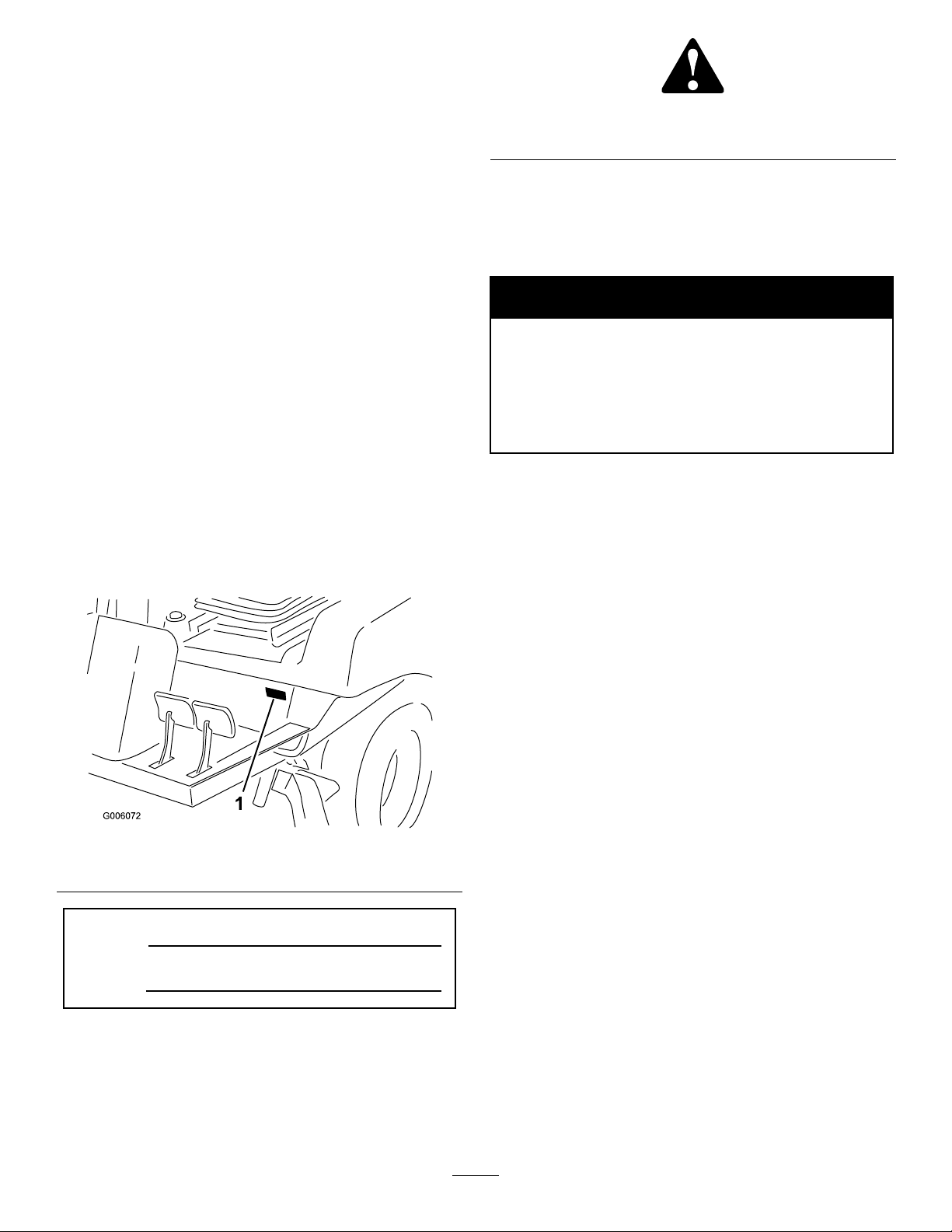
SafetyandInstructionalDecals
71-37 30
Safetydecalsandinstructionsareeasilyvisibletotheoperatorandarelocatednearanyareaof
potentialdanger.Replaceanydecalthatisdamagedorlost.
106-9206
1.Wheeltorquespecications
2.ReadtheOperator’sManual.
93-7841
1.Warning—readtheOperator’sManual.
106-6754
1.Warning—donottouchthehotsurface.
2.Cutting/dismembermenthazard,fanandentanglement
hazard,belt—stayawayfrommovingparts.
105-9584
71-3730
1.Hydraulicoil
2.ReadtheOperator’sManual.
93-6686
76-8750
108-9691
1.Unlocked
2.Locked
3.Fast
4.Continuousvariablesetting
5.Slow
6.Choke
7.Lowerthehopper10.Raisethecuttingunits
8.Raisethehopper
9.Lowerthecuttingunits
7
Page 8
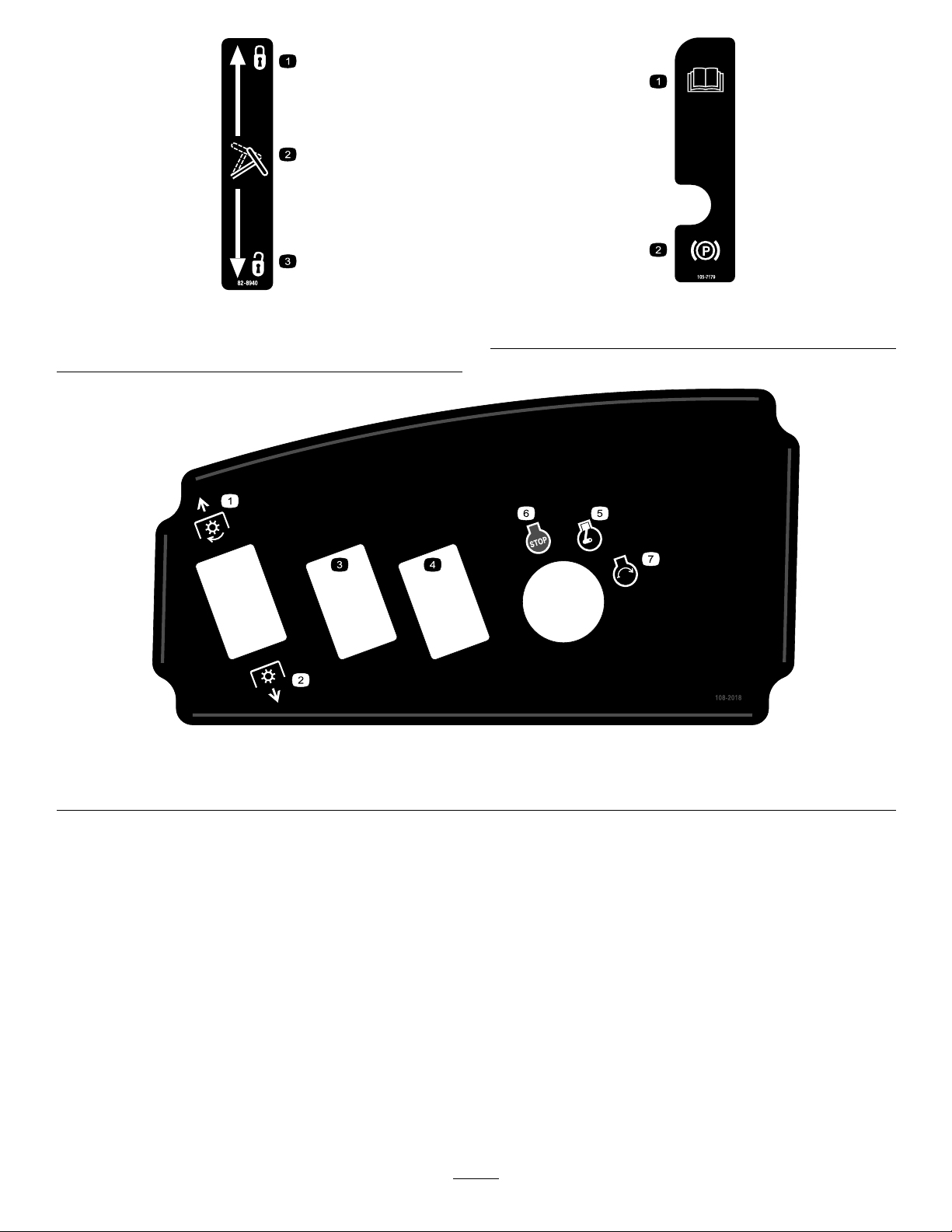
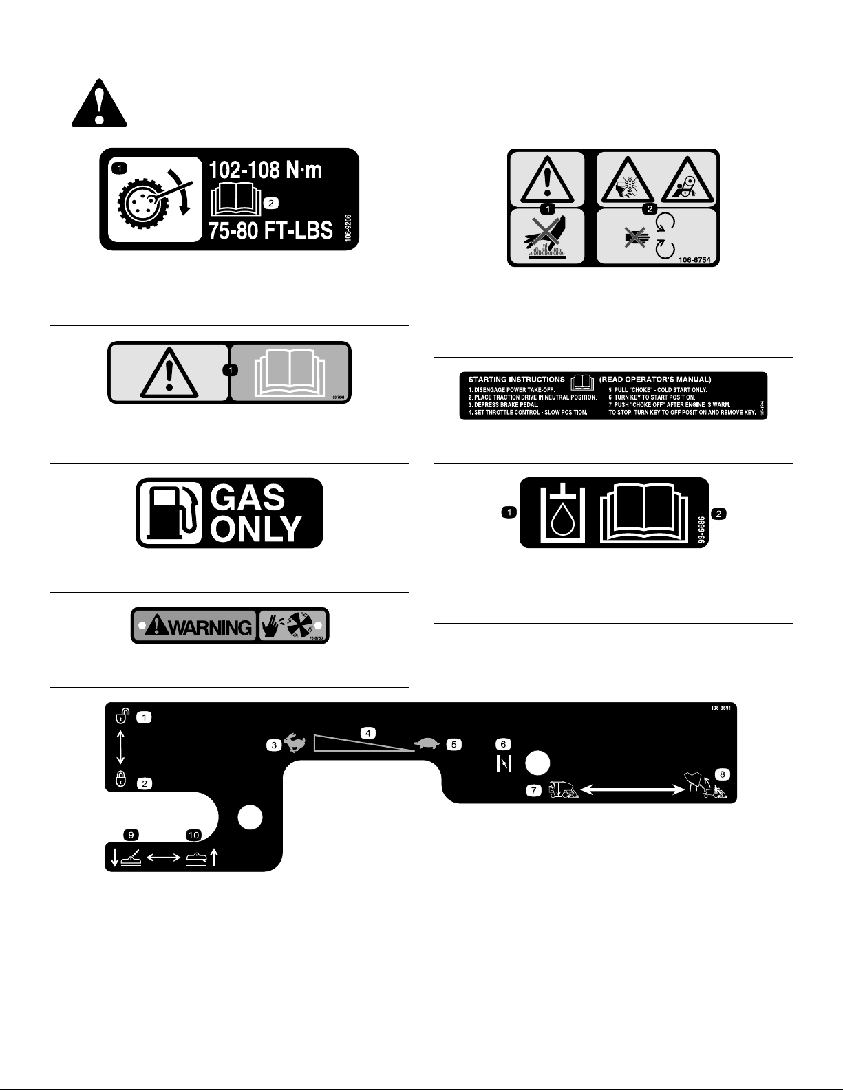
82-8940
1.Locked3.Unlocked
2.Tiltsteering
1.PTO–Off3.OptionalEquipment
2.PTO—On4.OptionalEquipment6.Engine—Stop
105-7179
1.ReadOperator’sManual.
2.Parkingbrake
108-2018
5.Engine—Run
7.Engine—Start
8
Page 9
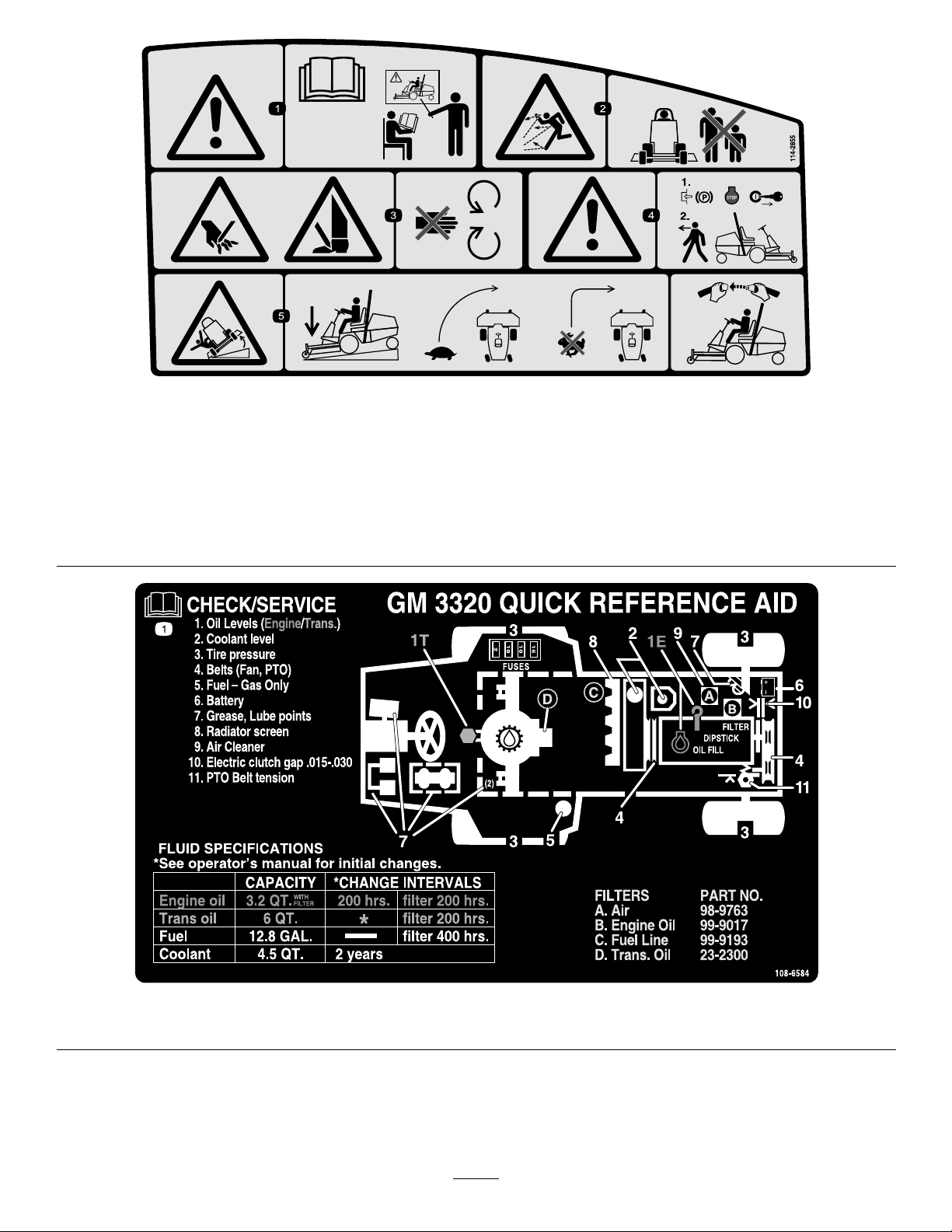
1.Warning—readtheOperator’sManual,
alloperatorsshouldbetrainedbefore
operatingthemachine.
2.Thrownobjecthazard—keep
bystandersasafedistancefromthe
machineandkeepthedeectorin
place.
114-2855
3.Cutting/dismembermenthazardof
handsorfeet,mowerblade—stay
awayfrommovingparts.
4.Warning—engagetheparkingbrake,
andremovetheignitionkeybefore
leavingthemachine.
5.Tippinghazard—whendrivingdown
slopes,lowerthecuttingunit,slow
machinebeforeturning,donotturnat
highspeeds;iftherollbarisinstalled,
weartheseatbelt.
1.ReadtheOperator’sManual.
108-6584
9
Page 10
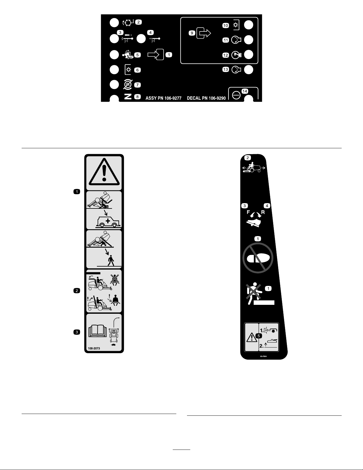
1.Inputs5.Inseat
2.Backlap
3.Hightemperatureshutdown
4.Hightemperaturewarning8.Neutral
6.PowerT ake-off(PTO)10.PowerT ake-off(PTO)
7.ParkingbrakeOff11.Start
106-9290
9.Outputs13.Start
14.Power
12.EnergizetoRun(ETR)
108-2073
1.Warning—thereisnorolloverprotectionwhentherollbaris
down.
2.Toavoidinjuryordeathfromarolloveraccident,keepthe
rollbarintheraisedandlockedpositionandweartheseat
belt.Lowertherollbaronlywhenabsolutelynecessary;do
notweartheseatbeltwhentherollbarisdown.
3.ReadtheOperator’sManual;driveslowlyandcarefully.
1.Nostep4.Traction-reverse
2.Tractionpedal
3.Traction-forward
10
93-7834
5.Warning—shutoffPTO
priortoraisingdecks;do
notoperatedeckswhen
theyareinraisedposition
Page 11
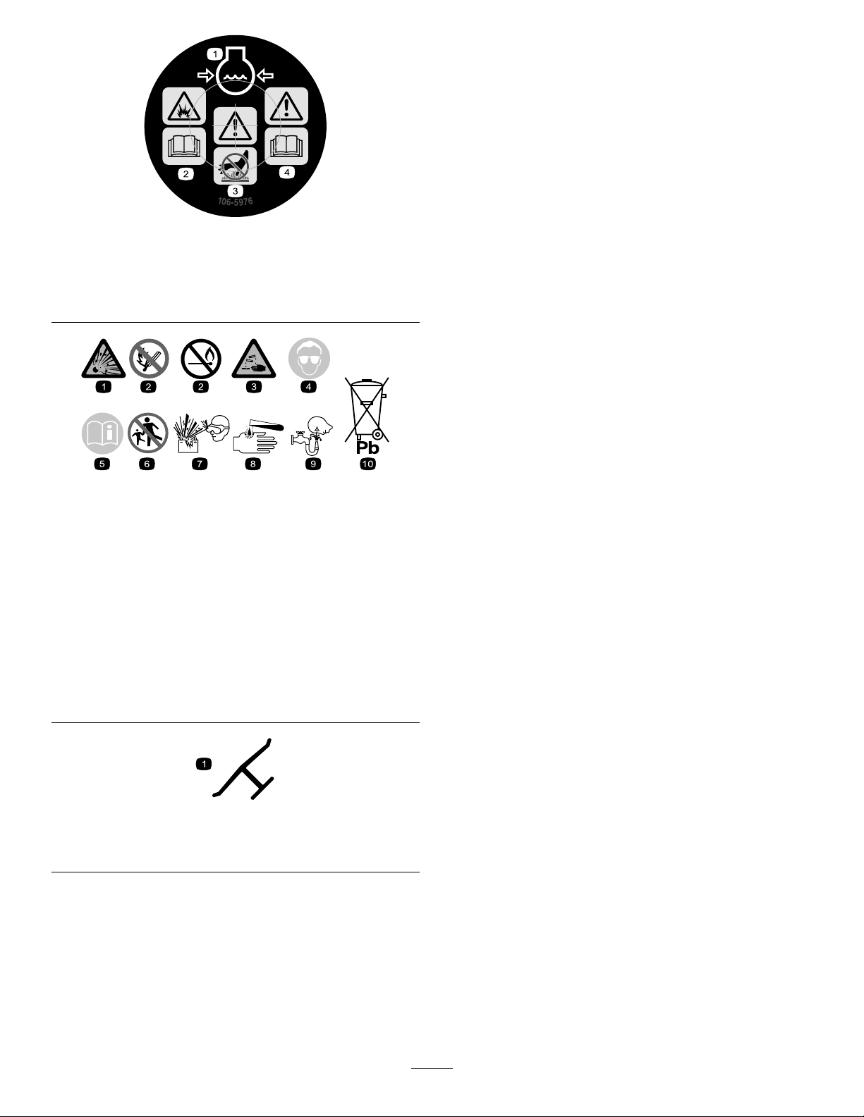
106-5976
1.Enginecoolantunder
pressure
2.Explosionhazard—read
theOperator’sManual.
3.Warning—donottouch
4.Warning—readthe
BatterySymbols
Someorallofthesesymbolsareonyourbattery
1.Explosionhazard
2.Nore,opename,or
smoking.
3.Causticliquid/chemical
burnhazard
4.Weareyeprotection9.Flusheyesimmediately
5.ReadtheOperator’s
Manual.
6.Keepbystandersasafe
7.Weareyeprotection;
8.Batteryacidcancause
10.Containslead;donot
thehotsurface.
Operator’sManual.
distancefromthebattery.
explosivegasescan
causeblindnessandother
injuries
blindnessorsevereburns.
withwaterandgetmedical
helpfast.
discard.
Manufacturer’sMark
1.Indicatesthebladeisidentiedasapartfromtheoriginal
machinemanufacturer.
11
Page 12

Setup
LooseParts
Usethechartbelowtoverifythatallpartshavebeenshipped.
ProcedureDescription
1
2
3
4
5
6
7
8
9
Steeringwheel
Cover
Handle1
Screws
Nopartsrequired
SeatBelt
Bolt2
Lockwasher2
Flatwasher2
ManualTube&Cap
R-clamp2
Nopartsrequired
Electrolyte(notincluded)A/R
Nopartsrequired
Rearweight(s)(notincluded)A/R
Qty.
Use
1
1
2
–
2
1
–
–
Installthesteeringwheel.
Installthehandletothehood.
Installtheseat.
Mounttheseatbelt.
Installthemanualtubeontheleft
undersideoftheseat.
AdjusttheROPS.
Activateandchargethebattery.
Checkthetirepressure.
Installtherearweight.
10
Nopartsrequired
MediaandAdditionalParts
Description
Operator’sManual
EngineOperator’sManual
PartsCatalog
OperatorTrainingMaterial
CerticateofQuality
IgnitionKey1
Note:Determinetheleftandrightsidesofthemachine
fromthenormaloperatingposition.
Note:Usethischartasachecklisttoensurethat
allpartsnecessaryforassemblyhavebeenreceived.
Withouttheseparts,totalset-upcannotbecompleted.
Somepartsmayhavealreadybeenassembledatthe
factory.
Qty.
–
1
1
1
1
1
AdjustCounterbalancePressure
Use
PTOuniversalshaftisattachedtomachine
frame.DONOTENGAGEPTOwithoutrst
removinguniversalshaftorcouplingittoa
suitableimplement.
12
Page 13

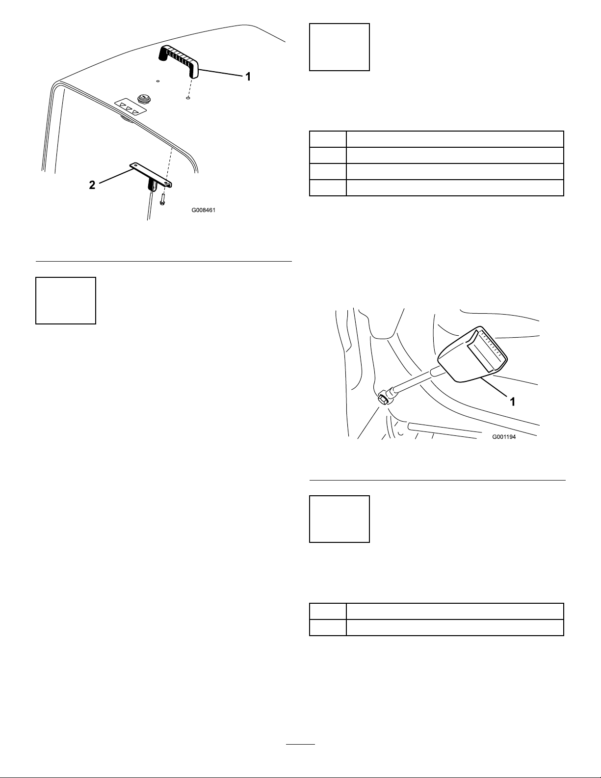
1
2
InstallingtheSteeringWheel
Partsneededforthisprocedure:
1
Steeringwheel
1
Cover
Procedure
1.Removethesteeringwheelfromtheshippingskid.
InstallingtheHandletothe
Hood
Partsneededforthisprocedure:
1Handle
2
Screws
Procedure
1.Removeanddiscardthe(2)screwsandnutssecuring
thehoodcablebracketandtotheundersideofthe
hood(Figure4).
Figure3
1.Steeringwheel
2.Jamnut
3.Dustcover6.Washer
2.Removethejamnutandwasherfromthesteering
shaft.Ensurethatthefoamcollaranddustcover
remainonthesteeringshaft(Figure3).
3.Slidethesteeringwheelandwasherontothesteering
shaft(Figure3).
4.Securethesteeringwheeltotheshaftwiththejam
nut.Tightenthejamnutto20-26ft-lb.
5.Mountthecovertothesteeringwheel(Figure3).
4.Foamcollar
5.Cover
Figure4
1.Hoodcablebracket
2.Mountthehandleandthecablebrackettothehood
with(2)screws(Figure5).
13
Page 14
4
InstallingtheSeatBelt
Partsneededforthisprocedure:
2
SeatBelt
2Bolt
2Lockwasher
2Flatwasher
Figure5
1.Handle2.Hoodcablebracket
3
InstallingtheSeat
NoPartsRequired
Procedure
TheGroundsmaster3320isshippedwithouttheseat
assembly.TheSeat,Model30398andtheMechanical
SeatSuspensionKit,ModelNo.30312orthePneumatic
SeatSuspensionKit,ModelNo.30313mustbeobtained
andinstalled.Refertotheseatkitforinstallation
instructions.
Note:AnAuxiliaryPowerUnitKit,ModelNo.30382,
mustbeobtainedandinstalledbeforeinstallinga
PneumaticSuspensionSeatKittothemachine.
Procedure
Installeachendoftheseatbeltintheholesintheback
oftheseatwith(2)7/16x1inchbolts,7/16inch
atwashersand7/16lockwashers(Figure6).Tighten
securely.Thelatchsideofthebeltistobemountedto
theleftsideoftheseat.
Figure6
1.Seatbelt
5
InstallingtheManualTube
Partsneededforthisprocedure:
1
ManualTube&Cap
2R-clamp
Procedure
1.RemovemanualtubeandR–clampssecuredto
theseatplate.Discardthe(2)mountingboltsand
atwashers.
14
Page 15

2.Removethe2nutsandvinylcaps(ifpreviously
installed)securingtheupperseatbrackettotheleft
sideoftheseatsuspension(Figure7).
Figure7
1.R-clamps4.Manualtube
2.Upperseatbracket5.Vinylcap
3.Seatsuspension
Figure8
1.Rollbar3.Hairpincotterpin
2.Pin
2.Raisetherollbartotheuprightpositionandinstall
thetwopinsandsecurethemwiththehairpincotter
pins(Figure8).
Note:Lowerrollbarslowlysodamagetohooddoes
notoccur.
3.LooselymounttheR–clampstotheseatbracket
studswiththe2nutspreviouslyremoved(Figure7).
TheR–clampsaretobepositionedundertheseat
suspensiontabs.
4.InstallthemanualtubeintotheR–clampsand
tightenthenuts(Figure7).
5.Insertthevinylcapsontotheseatbracketstuds.
6
AdjustingtheROPS
NoPartsRequired
Procedure
1.Removethehairpincotterpinsandremovethetwo
pins(Figure8).
7
ActivatingandChargingthe
Battery
Partsneededforthisprocedure:
A/RElectrolyte(notincluded)
Procedure
Useonlyelectrolyte(1.265SpecicGravity)toll
batteryinitially.
1.Removethebatteryfromthemachine.
Important:Donotaddelectrolytewhilethe
batteryisinthemachine.Youcouldspillit,
causingcorrosion.
2.Cleanthetopofthebatteryandremovethevent
caps(Figure9).
15
Page 16
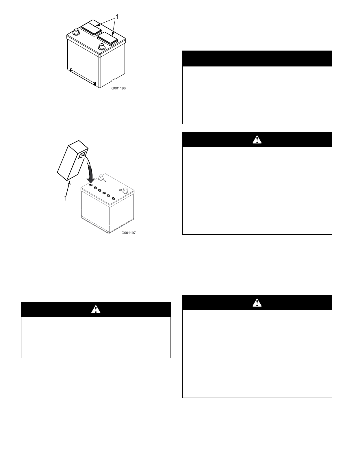
Figure9
1.Ventcaps
3.Carefullylleachcellwithelectrolyteuntiltheplates
arecoveredwithabout1/4inch(6mm)ofuid.
Note:Afterthebatteryhasbeenactivated,add
onlydistilledwatertoreplacenormalloss,although
maintenance–freebatteriesshouldnotrequirewater
undernormaloperatingconditions.
Warning
CALIFORNIA
Proposition65Warning
Batteryposts,terminals,andrelated
accessoriescontainleadandleadcompounds,
chemicalsknowntotheStateofCalifornia
tocausecancerandreproductiveharm.
Washhandsafterhandling.
Batteryterminalsormetaltoolscouldshort
againstmetaltractorcomponentscausing
sparks.Sparkscancausethebatterygassesto
explode,resultinginpersonalinjury.
Figure10
1.Electrolyte
4.Allowapproximately20to30minutesforthe
electrolytetosoakintotheplates.Rellasnecessary
tobringtheelectrolytetowithinabout1/4inch(6
mm)ofthebottomofthellwell(Figure10).
Chargingthebatteryproducesgassesthatcan
explode.
Neversmokenearthebatteryandkeepsparks
andamesawayfrombattery.
5.Connecta3to4ampbatterychargertothebattery
posts.Chargethebatteryatarateof3to4amps
untilthespecicgravityis1.250orhigherandthe
temperatureisatleast60degreesF(16degreesC)
withallcellsgassingfreely.
•Whenremovingorinstallingthebattery,do
notallowthebatteryterminalstotouchany
metalpartsofthetractor.
•Donotallowmetaltoolstoshortbetween
thebatteryterminalsandmetalpartsofthe
tractor.
7.Reinstallthebatterytothemachine.
8.First,installthepositivecable(red)tothepositive
(+)terminalandthenthenegativecable(black)to
thenegative(–)terminalofthebattery(Figure11).
Slidetherubberbootoverthepositiveterminalto
preventapossibleshortfromoccurring.
Incorrectbatterycableroutingcoulddamage
themachineandcablescausingsparks.Sparks
cancausethebatterygassestoexplode,
resultinginpersonalinjury.
•Alwaysdisconnectthenegative(black)
batterycablebeforedisconnectingthe
positive(red)cable.
•Alwaysconnectthepositive(red)battery
cablebeforeconnectingthenegative(black)
cable.
6.Whenthebatteryischarged,disconnectthecharger
fromtheelectricaloutletandbatteryposts.
16
Page 17

Figure11
1.Positive(+)2.Negative(-)
Connectingcablestothewrongpostcould
damagetheelectricalsystemandresultin
personalinjury.
Note:Makesurebatterycablesareroutedawayfrom
anysharpedgesormovingparts.
8
CheckingtheTirePressure
NoPartsRequired
Procedure
Thetiresareover–inatedforshipping.Therefore,
releasesomeoftheairtoreducethepressure.Correct
airpressureinfrontandreartiresis20psi.
17
Page 18

9
InstallingtheRearWeight
Partsneededforthisprocedure:
A/RRearweight(s)(notincluded)
Procedure
TheGroundsmaster3320SeriesTractionUnitscomplywithCENstandardEN836:1997,ISOstandard5395:1990
andtheANSIB71.4–2004Standardwhenequippedwithrearweight.215lb.ofrearweightisinstalledatthe
factory.Usethechartbelowtodeterminethecombinationsofadditionalweightrequired.Orderpartsfrom
yourlocalAuthorizedToroDistributor.
CuttingUnit
Description
52”SideDischarge
Deck(Model30555)
52”SideDischarge
Deckwith15cu.
ft.Hopper
62”RearDischarge
Deck(Model30403
w/30305)
62”Guardian
RecyclerDeck
(Model30403w/
30306)
60”SideDischarge
Deck(Model30366)
60”SideDischarge
Deckwith15cu.
ft.Hopper
RearWeight
Required
0lb0lb
0lb
0lb0lb
or
or
0lb
LeftSide
Weight
Required
180lb*
75lb**77–6700
WeightPart
Number
———
*77–6700
&&
92–9670BracketKit1
&&
24–5780RearWeightKit1
&&
24–5790RearWeight-35lb1
325–8
3253–7
3217–9
———
WeightDescription
75lbWheelWeight1
Bolt–1/2–13x2”
Lockwasher–1/2
Nut–1/2
75lbWheelWeight1
Quantity
2
2
2
18
Page 19

72”SideDischarge
Deck(Model30368)
or
72”RearDischarge
Deck(Model30404
w/30303)
or
72”Guardian
RecyclerDeck
(Model30404w/
30304)
70lb0lb24–5780RearWeightKit1
*75lbwheelweight(includedwith15cufthopper)requiredonleftwheel
10
AdjustingtheCounterbalance
Pressure
NoPartsRequired
Procedure
Forbestperformance,thecuttingunitbounceon
uneventurfisminimalanditdoesnotrideheavilyover
atterrain.Ifscalpingoccursorthecutisunevenfrom
sidetoside,theremaybetoomuchweightonthedeck
andtheweightmayhavetobetransferredtothetraction
unit:i.e.increasedcounterbalancepressure.
Bycontrast,iftoomuchweightistransferredtothe
tractionunit,thedeckwillbounceexcessivelyandthe
cutwillbeuneven.Ifthecuttingunitdoesnotperform
properly,adjustthecounterbalancepressureasfollows:
1.Ensuretheparkingbrakeisset,thePTOswitchis
inOFFpositionandtheliftleverisintheFLOAT
position.
2.Connectapressuregaugetothetestportbehindthe
rightliftcylinder(Figure12).
Figure12
1.TestPort
2.Rightliftcylinder
3.Loosenthejamnutatthebottomofthe
counterbalancevalve(Figure13).Thevalveis
locatedontherightsideofthemachine.
1.Liftvalve
2.Counterbalancevalve4.Spool
19
Figure13
3.Jamnut
Page 20

4.Starttheengineandsetthethrottletohighidle.
5.UsinganAllenwrench,adjusttheliftvalvespool
untilthedesiredpressureisattainedonthegauge.
Seethechartbelowfortherecommendedpressure
settingforthecuttingdeck.
CuttingDeckCounterbalancePressure
52”SideDischargeDeck
(Model30555)
60”SideDischargeDeck
(Model30366)
or
62”RearDischargeDeck
(Model30403w/30305)
or
62”GuardianRecyclerDeck
(Model30403w/30306)
72”SideDischargeDeck
(Model30368)
or
72”RearDischargeDeck
(Model30404w/30303)
or
72”GuardianRecyclerDeck
(Model30404w/30304)
100psi
175psi
220psi
ProductOverview
Controls
ServiceBrakes
Theleftandrightbrakepedals(Figure14)areconnected
totheleftandrightfrontwheels.Sincebothbrakes
workindependentlyofeachother,thebrakescanbe
usedtoturnsharplyortoincreasetractionifonewheel
tendstoslipwhileoperatingoncertainslopeconditions.
However,wetgrassorsoftturfcouldbedamagedwhen
brakesareusedtoturnsharply.Tomakea“quick-stop”,
depressbothbrakepedalstogether.Alwayslockbrakes
togetherwhentransportingthetractionunit.
6.Stoptheengine.
7.Tightenthejamnutontheliftvalve.Torquethenut
to10–12ft–lb.
8.Removethepressuregaugefromthetestport.
1.Parkingbrakeknob
2.Rightbrakepedal
1.Leftbrakepedal
2.Rightbrakepedal
Figure14
3.Leftbrakepedal
Figure15
3.Lockarm
TractionPedal
Tractionpedal(Figure16)hastwofunctions:oneisto
makethemachinemoveforward,theotheristomakeit
20
Page 21

moverearward.Usingtheheelandtoeoftherightfoot,
depresstopofpedaltomoveforwardandbottomof
pedaltomoverearward.Groundspeedisproportionate
tohowfarpedalisdepressed.Formaximumground
speed,tractionpedalmustbefullydepressedwhile
throttleisinFASTposition.Maximumspeedforwardis
10mph(16Km/hr)(approxamately).Togetmaximum
powerunderheavyloadorwhenascendingahill,have
throttleinFASTpositionwhiledepressingtraction
pedalslightlytokeepenginerpmhigh.Whenengine
rpmbeginstodecrease,releasetractionpedalslightly
toallowrpmtoincrease.
Figure17
1.Tiltsteeringcontrol
Neverraisedeckwhilebladesarerotating
becauseitishazardous.
Figure16
1.Tractionpedal
ParkingBrake
Whenevertheengineisshutoff,theparkingbrakemust
beengagedtopreventaccidentalmovementofthe
machine.Toengagetheparkingbrake,pushlockarm
(Figure15)onleftbrakepedalsothatitlockstogether
withtherightpedal.Next,pushdownfullyonboth
pedalsandpullparkingbrakeknobout(Figure14)then
releasethepedals.Toreleaseparkingbrake,depressboth
pedalsuntilparkingbrakeknobretracts.Beforestarting
theengine,however,lockarmmaybedisengagedfrom
leftbrakepedalsobothpedalsworkindependentlywith
eachfrontwheel.
TiltSteeringControl
Thetiltsteeringcontrolisaleveronrightsideofsteering
column(Figure17).Pullleverrearwardtoadjuststeering
wheeltodesiredforeoraftoperatingpositionandpush
leverforwardtolockadjustment.
HydraulicLiftLever
Thehydraulicliftlever(Figure18)hasthreelever
positionsthatactuatefouroperatingmodes;LIFT,
LOWER,FLOAT&HOLD .Tolowerthedeck,in
preparationformowing,movetheleverforwardand
thenallowthelevertofreelyreturn.Thiswillallow
thedecktodropatacontrolledrateandenablesthe
deckgroundfollowingoatfunction.Toraisethedeck
andholditinthetransportposition,pullandholdthe
liftleverrearwarduntilthedeckhasfullyraised,then
releasethelevertoallowittoreturn.Thedeckwillnow
holdinthetransportposition.Thedeckmustberaised
whentransportingbetweenmowinglocations.Thedeck
shouldbeloweredwhennotinuse.
PTOSwitch
PullupontheswitchknobtoENGAGEtheelectric
PTOclutch(Figure18).Pushdownontheknobto
DISENGAGEelectricPTOclutch.Theonlytimethe
PTOswitchshouldbeintheENGAGEpositionis
whentheimplementisdowninoperatingpositionand
readytobeginoperation.Iftheoperatorleavestheseat
whenthePTOswitchisengaged,thetractionunitwill
shutdown.Tore–engagethePTO,pushdownandpull
upontheknob.
21
Page 22

Figure18
1.Hydraulicliftlever7.Oilpressureindicator
2.PTOwitch8.Chargeindicator
3.Ignitionswitch
4.Throttle10.Powerpoint
5.Hourmeter
6.Enginecoolant
temperature
9.Liftleverlock
11.Choke
HourMeter
Thehourmeter(Figure18)registersaccumulatedhours
ofengineoperation.
EngineCoolantTemperatureWarning
Light
Thetemperaturewarninglight(Figure18)glowsand
theimplementstopsiftheenginecoolanttemperature
ishigh.Ifthemachineisnotstoppedandthecoolant
temperaturerisesanother20°F ,theenginewillkill.
Choke
Tostartengine,closecarburetorchoke(Figure18)
bypullingchokecontrolupward.Afterenginestarts,
regulatechoketokeepenginerunningsmoothly.As
soonaspossible,openthechokebypushingitinward.
Awarmenginerequireslittleornochoking.
FuelGauge
Thefuelgauge(Figure19)indicatesquantityoffuel
remaininginfueltank.
Figure19
1.Fuelgauge
IgnitionSwitch
ChargeIndicator
Illuminateswhensystemchargingcircuitmalfunctions
(Figure18).
OilPressureWarningLight
Theoilpressurewarninglight(Figure18)glowswhen
oilpressureinenginedropsbelowasafelevel.Iflow
oilpressureeveroccurs,stopengineanddeterminethe
cause.Repairthedamagebeforestartingtheengine
again.
LiftLeverLock
Lockliftlever(Figure18),inraisedposition,when
performingmaintenanceondeck.
Threepositions:OFF,RUNandSTART.(Figure18).
Throttle
Throttle(Figure18)isusedtooperateengineatvarious
speeds.Movingthrottleforwardincreasesenginespeed
—FAST;rearwarddecreasesenginespeed—SLOW .
Thethrottlecontrolsthespeedofthecutterbladesand,
inconjunctionwithtractionpedal,controlsground
speedofthemachine.Thedetentisthehighidle
position.
22
Page 23

Specications
Note:Specicationsanddesignaresubjecttochange
withoutnotice.
DimensionsandWeights(approx.)
Width(measuredfromoutside
offronttires)
Length(withoutcutterdeck)83.5inches(212cm)
Height(withROPSraised)77inches(196cm)
DryWeight(withoutcutter
deck)
47inches(120cm)
1555lb(705kg)
Attachments/Accessories
AselectionofToroapprovedattachmentsand
accessoriesareavailableforusewiththemachineto
enhanceandexpanditscapabilities.Contactyour
AuthorizedServiceDealerorDistributororgoto
www.Toro.comforalistofallapprovedattachments
andaccessories.
Operation
Note:Determinetheleftandrightsidesofthe
machinefromthenormaloperatingposition.
ThinkSafetyFirst
Pleasecarefullyreadallofthesafetyinstructions
andsymbolsinthesafetysection.Knowingthis
informationcouldhelpyouorbystandersavoidinjury.
Theuseofprotectiveequipment,suchasbutnot
limitedto,foreyes,ears,feet,andheadisrecommended.
Thismachineproducessoundlevelsinexcess
of85dBAattheoperator’searandcancause
hearinglossthroughextendedperiodsof
exposure.
Wearhearingprotectionwhenoperatingthis
machine.
CheckingtheEngineOil
ServiceInterval:Beforeeachuseordaily—Checkthe
engineoil.
Theengineisshippedwithoilinthecrankcase;
however,theoillevelmustbecheckedbeforeandafter
theengineisrststarted.
Crankcasecapacityisapproximately3.2quarts(3l)
withthelter.
Usehigh-qualityengineoilthatmeetsthefollowing
specications:
APIClassicationLevelRequired:SJ,SK,SLorhigher.
Preferredoil:SAE10W–30(alltemperatures)
Alternateoil:SAE5W–30(alltemperatures)SAE30
(above32F)
ToroPremiumEngineoilisavailablefromyour
distributorin10W–30viscosity.Seethepartscatalog
forpartnumbers.
1.Parkthemachineonalevelsurface,lowerthe
cuttingdeck,stoptheengineandremovethekey
fromtheignitionswitch.Openthehood.
2.Removethedipstick(Figure20),wipeitcleanand
reinstallthedipstick.Removethedipstickand
checktheoillevel.Theoillevelshouldbeuptothe
FULLmarkonthedipstick
23
Page 24

Figure20
1.Dipstick
3.IftheoillevelisbelowtheFULLmark,remove
thellcap(Figure20)andaddoiluntilitlevel
reachestheFULLmarkonthedipstick.DONOT
OVERFILL.
4.Installtheoilllcapandclosethehood.
Iftheenginehasbeenrunning,pressurizedhot
coolantcanescapewhentheradiatorcapis
removedandcauseburns.
1.Checkthelevelofthecoolantintheexpansiontank
(Figure22).Thecoolantlevelshouldbebetween
themarksonthesideofthetank.
Figure22
1.Expansiontank
Figure21
1.Oilll
CheckingtheCoolingSystem
ServiceInterval:Beforeeachuseordaily
Cleandebrisoffthescreenandtheradiator/oilcooler
daily,moreoftenifconditionsareextremelydustyand
dirty;refertosectiononEngineCoolingSystem.
Thecoolingsystemislledwitha50/50solutionof
waterandpermanentethyleneglycolantifreeze.Check
thelevelofthecoolantintheexpansiontankatthe
beginningofeachdaybeforestartingtheengine.The
capacityofthecoolingsystemis4qt(3.7l).
2.Ifcoolantlevelislow ,removeexpansiontankcap
andreplenishthesystem.DONOTOVERFILL.
3.Installexpansiontankcap.
CheckingtheHydraulic
System
ServiceInterval:Beforeeachuseordaily
Themachinesreservoirislledatthefactorywith
approximately5quarts(4.7l)ofhighqualityhydraulic
uid.Checkthelevelofthehydraulicuidbefore
theengineisrststartedanddailythereafter.The
recommendedreplacementuidis:
ToroPremiumTransmission/HydraulicTractor
Fluid
(Availablein5gallonpailsor55gallondrums.Seeparts
catalogorTorodistributorforpartnumbers.)
Alternateuids:IftheTorouidisnotavailable,other
petroleum–basedUniversalTractorHydraulicFluids
(UTHF)maybeusedprovideditsspecicationsfall
withinthelistedrangeforallthefollowingmaterial
propertiesanditmeetsindustrystandards.Wedonot
recommendtheuseofsyntheticuid.Consultwith
yourlubricantdistributortoidentifyasatisfactory
24
Page 25

productNote:Torowillnotassumeresponsibilityfor
damagecausedbyimpropersubstitutions,souseonly
productsfromreputablemanufacturerswhowillstand
behindtheirrecommendation.
3.Threaddipstickllcapnger-tightontollerneck.
Itisnotrecommendedtotightencapwithawrench.
4.Checkallhosesandttingsforleaks.
MaterialProperties:
Viscosity,ASTMD445cSt@40C.55to62cSt@
100C9.1to9.8
ViscosityIndexASTMD2270140–152
PourPoint,ASTMD97–35Fto–46F
IndustrySpecications:
APIGL–4,AGCOPoweruid821XL,FordNew
HollandFNHA–2–C–201.00,KubotaUDT,John
DeereJ20C,Vickers35VQ25andVolvoWB–101/BM.
Note:Manyhydraulicuidsarealmostcolorless,
makingitdifculttospotleaks.Areddyeadditivefor
thehydraulicsystemoilisavailablein2/3oz.(20ml)
bottles.Onebottleissufcientfor4–6gal(15–221)
ofhydraulicoil.Orderpartno.44–2500fromyour
authorizedTorodistributor.
1.Positionmachineonalevelsurface.Placeallcontrol
inneutralpositionandstarttheengine.Runengine
atlowestpossibleRPMtopurgethesystemofair.
DONOTENGAGEPTO.Cyclesteeringwheel
severaltimesfullytotheleftandright.Raisethe
decktoextendliftcylinders,aimingsteeringwheels
straightforwardandstoptheengine.
2.Removedipstickcap(Figure23)fromllerneck
andwipeitwithacleanrag.Screwdipstickcap
nger-tightontollerneck;thenremoveitand
checklevelofuid.Iflevelisnotwithin1/2inch
(13mm)fromthegrooveinthedipstick(Figure23),
addenoughhighqualityhydraulicuidtoraiselevel
togroovemark.Donotoverll.
FillingtheFuelTank
Fueltankcapacityisapproximately12.8gallon(48.5l).
1.Usingacleanrag,cleanareaaroundfueltankcap.
2.Removecapfromthefueltank(Figure24).
Figure24
1.Fueltankcap
3.Fillthetankuntilthelevelistothebottomofthe
llerneckwithunleadedfuel.
4.Installfueltankcaptightlyafterllingtank.
Undercertainconditions,fuelandfuelvapors
arehighlyammableandexplosive.Areor
explosionfromfuelcanburnyouandothers
andcancausepropertydamage.
Figure23
1.Hydraulicsystemreservoiruid/adddipstickcap
•Useafunnelandllthefueltankoutdoors,
inanopenarea,whentheengineisoffand
iscold.Wipeupanyfuelthatspills.
•Donotllthefueltankcompletelyfull.Add
fueltothefueltankuntilthelevelistothe
bottomofthellerneck.
•Neversmokewhenhandlingfuel,andstay
awayfromanopenameorwherefuel
fumesmaybeignitedbyaspark.
•Storefuelinaclean,safety-approved
containerandkeepthecapinplace.
25
Page 26

UsingtheRolloverProtection
System(ROPS)
Toavoidinjuryordeathfromrollover:keepthe
rollbarintheraisedlockedpositionanduse
theseatbelt.
Ensurethattherearpartoftheseatissecured
withtheseatlatch.
Thereisnorolloverprotectionwhentherollbar
isinthedownposition.
•Lowertherollbaronlywhenabsolutely
necessary.
Figure25
1.Rollbar3.Hairpincotterpin
2.Pin
2.Lowertherollbartothedownposition.
3.Installthetwopinsandsecurethemwiththehairpin
cotterpins(Figure25).
•Donotweartheseatbeltwhentherollbaris
inthedownposition.
•Driveslowlyandcarefully.
•Raisetherollbarassoonasclearance
permits.
•Checkcarefullyforoverheadclearances(i.e.
branches,doorways,electricalwires)before
drivingunderanyobjectsanddonotcontact
them.
•Lowerrollbarslowlysodamagetohood
doesnotoccur.
Important:Lowertherollbaronlywhen
absolutelynecessary.
1.Tolowertherollbar,removethehairpincotterpins
andremovethetwopins(Figure25).
Important:Alwaysusetheseatbeltwiththe
rollbarintheraisedposition.
4.Toraisetherollbar,removethehairpincotterpins
andremovethetwopins(Figure25).
5.Raisetherollbartotheuprightpositionandinstall
thetwopinsandsecurethemwiththehairpincotter
pins(Figure25).
Starting/StoppingtheEngine
1.Ensureparkingbrakeisset,PTOswitchisin
OFFpositionandliftleverisinTRANSPORTor
FLOATposition.Removefootfromtractionpedal
andinsureitisinneutral.
2.Pullchoketofullchokepositionandmovethrottle
controltoSLOWposition.
3.TurnkeyinignitionswitchtoSTARTposition.
Releasekeyimmediatelywhenenginestartsand
allowittoreturntoRUNposition.Regulatechoke
tokeepenginerunningsmoothly.
Note:Donotrunstartermotormorethan20
secondsatatimeorprematurestarterfailuremay
result.Ifenginefailstostartafter20seconds,
turnkeytoOFFposition,recheckcontrolsand
procedures,wait10additionalsecondsandrepeat
starteroperation.
4.Whenengineisstartedforthersttime,or
afterengineoilchange,oroverhaulofengine,
transmissionoraxle,operatethemachineinforward
andreverseforonetotwominutes.Alsooperatethe
liftleverandPTOlevertoensureproperoperation
ofallparts.Turnpowersteeringwheeltotheleft
26
Page 27

andrighttochecksteeringresponse.Thenshut
engineoffandcheckuidlevels,checkforoilleaks,
loosepartsandanyothernoticeablemalfunctions.
Shutengineoffandwaitforallmovingpartsto
stopbeforecheckingforoilleaks,looseparts
orothermalfunctions.
5.Tostopengine,movethrottlecontrolbackwardto
SLOWposition,movePTOswitchtoOFFposition
androtateignitionkeytoOFF.Removekeyfrom
switchtopreventaccidentalstarting.
CheckingInterlockSystem
Thepurposeofthesafetyinterlocksystemistoprevent
theenginefromcrankingorstartingunlessthetraction
pedalisinneutralandthePTOswitchisintheOFF
position.Inaddition,theenginewillstopwhenthe
PTOcontrolisengagedortractionpedalisdepressed
withoperatorofftheseatorwhenparkingbrakeis
engaged.
correctly;thus,proceedtostep5Ifenginedoesnot
stop,thereisamalfunctionintheinterlocksystem.
5.Engagetheparkingbrake.Depressthetraction
pedalwhileengineisrunningandthePTOlever
isdisengaged.Theengineshouldstopwithin2
seconds.Ifenginestops,theswitchisoperating
correctly;thus,continueoperation.Ifenginedoes
notstop,thereisamalfunctionintheinterlock
system.
PushingOrTowingthe
Machine
Inanemergency,themachinecanbepushedortowed
foraveryshortdistance.However,T orodoesnot
recommendthisasstandardprocedure.
Important:Donotpushortowthemachine
fasterthan2to3mph(3.2to4.8Km/hr)because
transmissionmaybedamaged.Ifthemachine
mustbemovedaconsiderabledistance,transport
itonatruckortrailer.Whenevermachineis
pushedortowed,by-passvalvemustbeopen.
1.Loosentheknobandremovetheaccesscoverat
therearoftheseatmountingplate(Figure26).
Ifsafetyinterlockswitchesaredisconnected
ordamagedthemachinecouldoperate
unexpectedlycausingpersonalinjury.
•Donottamperwiththeinterlockswitches.
•Checktheoperationoftheinterlock
switchesdailyandreplaceanydamaged
switchesbeforeoperatingthemachine.
1.MovePTOswitchtoOFFpositionandremove
footfromtractionpedalsoitisfullyreleased.
2.RotatetheignitionkeytoSTART.Engineshould
crank.Ifenginecranks,proceedtostep3.Ifengine
doesnotcrank,theremaybeamalfunctioninthe
interlocksystem.
3.RaiseofftheseatandengagethePTOswitch
whiletheengineisrunning.Theengineshould
stopwithin2seconds.Ifenginestops,theswitch
isoperatingcorrectly;thus,proceedtostep4.If
enginedoesnotstop,thereisamalfunctioninthe
interlocksystem.
Figure26
1.Accesscoverknob
2.Depressandholdthepinslocatedinthecenterof
thetwo(2)checkvalveassembliesinthetopofthe
transmission(Figure27)whilepushingortowing
themachine.Figure27isshownwithseatandseat
mountingplateremoved.
4.Raiseofftheseatanddepressthetractionpedal
whileengineisrunningandthePTOleveris
disengaged.Theengineshouldstopwithin2
seconds.Ifenginestops,theswitchisoperating
27
Page 28

Figure27
1.Transmissioncheckvalveby–passpins(2)
Thismachineproducessoundlevelsinexcess
of85dBAattheoperatorsearandcancause
hearinglossthroughextendedperiodsof
exposure.
Wearhearingprotectionwhenoperatingthis
machine.
3.Starttheenginemomentarilyaftertherepairsare
completedandmakesurethepinsareinthefull
disengaged(fullyup)position.
Important:Runningthemachinewithby-pass
valveopenwillcausethetransmissionto
overheat.
4.Reinstalltheaccesscover.
OperatingCharacteristics
PracticedrivingtheGROUNDSMASTER3320
beforeinitialoperationbecauseithasahydrostatic
transmissionanditscharacteristicsaredifferentthan
someturfmaintenancemachines.Somepointsto
considerwhenoperatingthetractionunitanddeck
arethetransmission,enginespeed,loadonthecutting
blades,andtheimportanceofthebrakes.
Tomaintainenoughpowerforthetractionunitand
deckwhilemowing,regulatetractionpedaltokeep
enginerpmhighandsomewhatconstant.Agood
ruletofollowis:decreasegroundspeedastheload
onthecuttingbladesincreases;andincreaseground
speedasloadonthebladesdecreases.Thisallowsthe
engine,workingwiththetransmission,tosensethe
propergroundspeedwhilemaintaininghighbladetip
speednecessaryforgoodquality-of-cut.Therefore,
allowtractionpedaltomoveupwardasenginespeed
decreases,anddepresspedalslowlyasspeedincreases.
Bycomparison,whendrivingfromoneworkareato
another—withnoloadanddeckraised—havethrottle
inFASTpositionanddepresstractionpedalslowlybut
fullytoattainmaximumgroundspeed.
Adequaterearweightisnecessarytoprevent
therearwheelsfromleavingtheground.Do
notstopsuddenlywhiledeckorimplementis
raised.Donottraveldownhillwiththedeckor
implementraised.Iftherearwheelleavesthe
ground,steeringislost.
Anothercharacteristictoconsideristheoperationof
thebrakes.Thebrakescanbeusedtoassistinturning
themachine;however,usethemcarefully,especially
onsoftorwetgrassbecausetheturfmaybetorn
accidentally.Thebrakescanbeusedtogreatadvantage
tocontrolthedirectionofthedeckwhentrimming
alongfencesorsimilarobjects.Theotherbenetof
thebrakesistomaintaintraction.Forexample;in
someslopeconditions,theuphillwheelslipsandloses
traction.Ifthissituationoccurs,depressuphillbrake
pedalgraduallyandintermittentlyuntiltheuphillwheel
stopsslipping;thus,increasingtractiononthedownhill
wheel.Ifindependentbrakingisnotdesired,engage
theleveronleftbrakepedalwithrightpedal.This
providessimultaneousbrakingatbothwheels.
Beforestoppingtheengine,disengageallcontroland
movethrottletoSLOW .MovingthrottletoSLOW
reduceshighenginespeed,noiseandvibration.Turn
ignitionkeytoOFFtostoptheengine.
StandardControlModule
(SCM)
TheStandardControlModuleisa”potted”electronic
deviceproducedina”onesizetsall”conguration.
Themoduleusessolidstateandmechanical
componentstomonitorandcontrolstandardelectrical
featuresrequiredforsafeproductoperation.
Themodulemonitorsinputsincludingneutral,parking
brake,PTO,start,backlap,andhightemperature.The
moduleenergizesoutputsincludingPTO,Starter,and
ETR(energizetorun)solenoid.
28
Page 29

Themoduleisdividedintoinputsandoutputs.Inputs
andoutputsareidentiedbyyellowLEDindicators
mountedontheprintedcircuitboard.
Thestartcircuitinputisenergizedby12VDC.All
otherinputsareenergizedwhenthecircuitisclosedto
ground.EachinputhasaLEDthatisilluminatedwhen
thespeciccircuitisenergized.UsetheinputLED’s
forswitchandinputcircuittroubleshooting.
Outputcircuitsareenergizedbyanappropriatesetof
inputconditions.ThethreeoutputsincludePTO,ETR,
andSTART.OutputLED’smonitorrelaycondition
indicatingthepresenceofvoltageatoneofthree
specicoutputterminals.
Outputcircuitsdonotdetermineoutputdeviceintegrity
soelectricaltroubleshootingincludesoutputLED
inspectionandconventionaldeviceandwireharness
integritytesting.Measuredisconnectedcomponent
impedance,throughwireharness(disconnectat
SCM),orbytemporarily“testenergizing”thespecic
component.
TheSCMdoesnotconnecttoanexternalcomputeror
handhelddevice,cannotbere–programmed,anddoes
notrecordintermittentfaulttroubleshootingdata.
ThedecalontheSCMonlyincludessymbols.Three
LEDoutputsymbolsareshownintheoutputbox.All
otherLED’sareinputs.Thechartbelowidentiesthe
symbols.
Figure28
1.Inputs5.Inseat
2.Backlap
3.Hightemperatureshutdown
4.Hightemperaturewarning8.Neutral
6.PowerT ake-off(PTO)10.PowerT ake-off(PTO)
7.ParkingbrakeOff11.Start
HerearethelogicaltroubleshootingstepsfortheSCM
device.
1.Determinetheoutputfaultyouaretryingtoresolve
(PTO,START,orETR).
2.Movekeyswitchto”ON”andensurethered
”power”LEDisilluminated.
3.MoveallinputswitchestoensureallLED’schange
state(Seat,Brake,TractionPedal,PTOandStart.
4.Positioninputdevicesatappropriatepositionto
achievetheappropriateoutput.Usethefollowing
9.Outputs13.Start
14.Power
12.EnergizetoRun(ETR)
logiccharttodeterminetheappropriateinput
condition.
5.IfspecicoutputLEDisilluminatedwithout
appropriateoutputfunction,checkoutputharness,
connections,andcomponent.Repairasrequired.
6.IfspecicoutputLEDisnotilluminated,check
bothfuses.
7.IfspecicoutputLEDisnotilluminatedandinputs
areinappropriatecondition,installnewSCMand
determineiffaultdisappears.
Note:Eachrow(across)inthelogicchartbelowidentiesinputandoutputrequirementsforeachspecicproduct
function.Productfunctionsarelistedintheleftcolumn.Symbolsidentifyspeciccircuitconditionincluding:
energizedtovoltage,closedtoground,andopentoground.
29
Page 30

INPUTSOUTPUTS
FunctionPower
ON
Start
Run(Off
Unit)
Run(On
Unit)
Mow
HiT emp
Warning
HiT emp
Shutdown
——
——
—
—
—
—
In
Neutral
OO
OO
Start
ON
Brake
ON
+
OOOOOON/AO
OO—(AN/A
O
OO
—
———
(—)Indicatesacircuitclosedtoground.–LEDON
(O)Indicatesacircuitopentogroundorde–energized
–LEDOFF
(+)Indicatesanenergizedcircuit(clutchcoil,solenoid,
orstartinput)LEDON.
“”ABlankindicatesacircuitthatisnotinvolvedwith
thelogic.
PTO
ON
InSeat
O
HiT emp
Shutdown
—
—
HiT emp
Warning
OON/A
OON/AO
OON/AO
—
Back
Lap
N/AOOO
++
++
+
+
++
O
O
O
O
(A)PTOinputmustbere–initiatedafterenginecool
down(cyclekeyon–off)
N/ANotapplicable
Totroubleshoot,turnonthekeywithoutstartingthe
engine.Identifythespecicfunctionthatdoesnot
workandworkacrossthelogicchart.Inspectthe
conditionofeachinputLED’stoensureitmatchesthe
logicchart.
IftheinputLED’sarecorrect,checktheoutput
LED.IftheoutputLEDisilluminatedbutthedevice
isnotenergized,measureavailablevoltageatthe
outputdevice,continuityofthedisconnecteddevice,
andpotentialvoltageonthegroundcircuit(oating
ground).Repairswillvarydependingonyourndings.
30
Page 31

Maintenance
RecommendedMaintenanceSchedule(s)
MaintenanceService
Interval
Aftertherst8hours
Aftertherst10hours
Aftertherst50hours
Beforeeachuseordaily
Every50hours
Every200hours
MaintenanceProcedure
•Replacethehydraulicoillter.
•Checkthebrakeoperation
•Checkthealternatorbelttension.
•CheckthePTObelttension.
•T orquewheellugnuts
•Changetheoilandoillter.
•Checkthebrakeoperation
•CheckthePTObelttension.
•Checktheengineoil.
•Cleandebrisoffthescreenandtheradiator/oilcooler.
•Checkthelevelofthehydraulicuid.
•Checkthescreenandradiator
•Lubricateallbearingsandbushings.(Lubricateallbearingsandbushingsdailywhen
conditionsaredustyanddirty.)
•Checktheelectrolytelevel.(Ifthemachineisinstorage,checktheelectrolytelevel
every30days.)
•Changetheoilandoillter.
•AdjustthePTOClutch
•Checktherearwheeltoe-in.
•Checkthealternatorbelttension.
•CheckthePTObelttension.
•Replacethehydraulicoillter.
•T orquewheellugnuts
•Inspectcoolingsystemhoses
•Checkrearwheeltoe-inandsteeringlinkage
•Servicetheaircleaner.(Servicemorefrequentlyinextremelydustyordirty
conditions.)
Every400hours
Every1,500hours
•Replacethefuelprelter
•Checkfuellinesandconnections.
•Coattransmissionbypasspinswithgrease
•AdjustvalvesandcheckengineRPM
•Replacethehydraulicoil.
•Replacemovinghoses
•Coolantsystem-ush/replaceuid
Ifyouleavethekeyintheignitionswitch,someonecouldaccidentlystarttheengineandseriously
injureyouorotherbystanders.
Removethekeyfromtheignitionanddisconnectthewirefromthesparkplugbeforeyoudoany
maintenance.Setthewireasidesothatitdoesnotaccidentallycontactthesparkplug.
31
Page 32

DailyMaintenanceChecklist
Duplicatethispageforroutineuse.
Fortheweekof:
MaintenanceCheckItem
Checkthesafetyinterlock
operation.
Checkthatthegrassdeector
isinthedownposition
Checkthebrakeoperation.
Checkthefuellevel.
Checktheengineoillevel.
Checkthecoolingsystem
uidlevel
Inspecttheairlterrestriction
indicator
Checktheradiatorand
screenfordebris
Checkforunusualengine
noises
Checkforunusualoperating
noises
Checkthetransmissionoil
level
Checkhydraulichosesfor
damage
Checkforuidleaks
Checkthetirepressure
Checktheinstrument
operation
Checktheconditionofthe
blades
Lubricateallthegrease
ttings
Touch-upanydamagedpaint
1
=Immediatelyaftereverywashing,regardlessoftheintervallisted
2
=Iftheindicatorshowsred
2
1
Mon.T ues.Wed.Thurs.Fri.
Sat.Sun.
Important:Refertoyourengine
NotationforAreasofConcern
Inspectionperformedby:
ItemDate
Operator’ s Man ual
foradditionalmaintenanceprocedures.
Information
32
Page 33

ServiceIntervalChart
Figure29
33
Page 34

Lubrication
GreasingtheBearingsAnd
Bushings
ServiceInterval:Every50hours(Lubricateallbearings
andbushingsdailywhenconditions
aredustyanddirty.)
Themachinehasgreasettingsthatmustbelubricated
regularlywithNo.2GeneralPurposeLithiumBase
Grease.Bearingsandbushingsmustbelubricateddaily
whenoperatingconditionsareextremelydustyand
dirty.Dustyanddirtyoperatingconditionscouldcause
dirttogetintothebearingsandbushings,resultingin
acceleratedwear.Lubricategreasettingimmediately
aftereverywashing,regardlessofintervalspecied.
Applyaliberalcoatingofgreasetothecheckvalvepins
onceeachyear(Figure27).Alsogreasethebearingsin
therearaxleevery500hours,oryearly,whichevercomes
rst(notshown).Thebearingandbushinglubrication
pointsare:
•PTOuniversalshaft(Figure30)
•Brakepivotbushings(Figure32)
Figure32
•Brakecables(drivewheelandbrakepedalends)
(Figure33)
•PTOtensionpivot(Figure33)
Figure30
•Liftarmpivotbushings(Figure31)
Figure33
•RearPTObearing(Figure33)
•Transmissionneutralshaft(Figure34)
Figure34
Figure31
34
Page 35

•Rearwheelspindlebushings(Figure35)
providegoodperformanceandlifeundernormaluse,
butperiodicinspectionsofbearingconditionandseal
integrityshouldbeconductedtoavoiddowntime.These
bearingsshouldbeinspectedseasonallyandreplacedif
damagedorworn.Bearingsshouldoperatesmoothly
withnodetrimentalcharacteristicssuchashighheat,
noise,loosenessorindicationsofcorrosion(rust).
Duetotheoperatingconditionsthesebearing/seal
packagesaresubjectto(i.e.sand,turfchemicals,water,
impacts,etc.)theyareconsiderednormalwearitems.
Bearingsthatfailduetocausesotherthandefectsin
materialsorworkmanshiparetypicallynotcovered
underwarranty.
Figure35
•Steeringplatebushings(Figure36)
•Axlepinbushing(Figure36)
Figure36
1.Wipegreasettingcleansoforeignmattercannotbe
forcedintothebearingorbushing.
Note:Bearinglifecanbenegativelyaffectedby
improperwashdownprocedures.Donotwash
downtheunitwhenitisstillhotandavoiddirecting
high–pressureorhighvolumesprayatthebearings.
2.Pumpgreaseintothebearingorbushing.
3.Wipeupexcessgrease.
Note:Bearingsrarelyfailfromdefectsinmaterialsor
workmanship.Themostcommonreasonforfailure
ismoistureandcontaminationworkingitswaypast
theprotectiveseals.Bearingsthataregreasedwillrely
uponregularmaintenancetopurgeharmfuldebrisfrom
thebearingarea.Sealedbearingsrelyonaninitial
llofspecialgreaseandarobustintegralsealtokeep
contaminantsandmoistureoutoftherollingelements.
Thesealedbearingsrequirenolubricationorshortterm
maintenance.Thisminimizesroutineservicerequired
andreducesthepotentialofturfdamageduetogrease
contamination.Thesesealedbearingpackageswill
35
Page 36

EngineMaintenance
GeneralAirCleaner
Maintenance
ServiceInterval:Every400hours(Servicemore
frequentlyinextremelydustyordirty
conditions.)
•Checkaircleanerbodyfordamagewhichcould
possiblycauseanairleak.Replaceadamagedair
cleanerbody .Checkthewholeintakesystemfor
leaks,damageorloosehoseclamps.
•Servicetheaircleanerlterwhenaircleanerindicator
(Figure37)showsredorevery400hours(more
frequentlyinextremedustyordirtyconditions).Do
notoverserviceairlter.
Figure38
1.Aircleanerlatch3.Rubberoutletvalve
2.Aircleanercover
2.Removethecoverfromtheaircleanerbody.Before
removingthelter,uselowpressureair(40psi,
cleananddry)tohelpremovelargeaccumulations
ofdebrispackedbetweenoutsideofprimarylter
andthecanister.Avoidusinghighpressureairwhich
couldforcedirtthroughthelterintotheintake
tract.Thiscleaningprocesspreventsdebrisfrom
migratingintotheintakewhentheprimarylteris
removed.
Figure37
1.Aircleanerindicator
•Besurethecoverisseatedcorrectlyandsealswith
theaircleanerbody.
ServicingtheAirCleaner
1.Pulllatchoutwardandrotateaircleanercover
counter–clockwise(Figure38).
3.Removeandreplacetheprimarylter(Figure39).
Cleaningoftheusedelementisnotrecommended
duetothepossibilityofdamagetotheltermedia.
Inspectthenewlterforshippingdamage,checking
thesealingendofthelterandthebody.Donotuse
adamagedelement.Insertthenewlterbyapplying
pressuretotheouterrimoftheelementtoseatitin
thecanister.Donotapplypressuretotheexible
centerofthelter.
Figure39
1.Filter
4.Cleanthedirtejectionportlocatedintheremovable
cover.Removetherubberoutletvalvefromthe
cover,cleanthecavityandreplacetheoutletvalve.
36
Page 37

5.Installthecoverorientingtherubberoutletvalvein
adownwardposition–betweenapproximately5:00
to7:00whenviewedfromtheend(Figure38).
6.Resetindicator(Figure37)ifshowingred.
ChangingtheEngineOilAnd
Filter
ServiceInterval:Aftertherst50hours—Changethe
oilandoillter.
Every200hours—Changetheoiland
oillter.
Ifpossible,runenginejustbeforechangingoilbecause
warmoilowsbetterandcarriesmorecontaminants
thancoldoil.
1.Positionmachineonalevelsurface.
2.Openthehood.Setdrainpanundertheoilpanand
inlinewithdrainplug(Figure40).
Figure41
1.Oillter
Figure40
1.Drainplug
3.Cleanareaarounddrainplug.
4.Removeoildrainplugandallowoiltoowinto
drainpan.
5.Removeandreplaceoillter(Figure41).
6.Afteroilisdrained,reinstalldrainplugandwipeup
anyoilthatisspilled.
7.Fillcrankcasewithoil;refertoCheckCrankcaseOil.
37
Page 38

FuelSystem
Maintenance
ServicingtheFuelSystem
FuelTank
Drainandcleanfueliftankbecomescontaminatedor
machineistobestoredforanextendedperiod.Use
cleansolventtoushoutthetank.
1.Lubricategasketonltercanisterwithcleanoil.
2.Installltercanisterbyhanduntilgasketcontacts
mountingsurface,thenrotateanadditional1/2turn.
ReplacingFuelPreFilter
ServiceInterval:Every400hours/Y early(whichever
comesrst)
1.Clampbothfuellinesthatconnecttothefuellterso
fuelcannotdrainwhenlinesareremoved(Figure42).
2.Loosenthehoseclampsatbothendsofthelter
andpullfuellinesofflter.
Undercertainconditions,fuelandfuelvapors
arehighlyammableandexplosive.Areor
explosionfromfuelcanburnyouandothers
andcancausepropertydamage.
•Useafunnelandllthefueltankoutdoors,
inanopenarea,whentheengineisoffand
iscold.Wipeupanyfuelthatspills.
•Donotllthefueltankcompletelyfull.Add
fueltothefueltankuntilthelevelistothe
bottomofthellerneck.
•Neversmokewhenhandlingfuel,andstay
awayfromanopenameorwherefuel
fumesmaybeignitedbyaspark.
•Storefuelinaclean,safety-approved
containerandkeepthecapinplace.
3.Slidehoseclampsontoendsoffuellines.Push
fuellinesontofuellterandsecurethemwithhose
clamps.Besurearrowonsideoflterpointstoward
theinjectionpump.
1.Fuelprelter
FuelLinesandConnections
ServiceInterval:Every400hours/Y early(whichever
comesrst)—Checkfuellinesand
connections.
Inspectfordeterioration,damageorlooseconnections.
Figure42
38
Page 39

ElectricalSystem
Maintenance
storedinalocationwheretemperaturesareextremely
high,thebatterywillrundownmorerapidlythanif
themachineisstoredinalocationwheretemperatures
arecool.
AdjustingthePTOClutch
ServiceInterval:Every200hours
Thepowertakeoffelectricclutchcanbeadjustedby
followingthefollowingprocedure:
1.Turnengineoffandremovetheignitionkey.Setthe
parkingbrake.Raisetheenginehoodandallowthe
enginetocool.
2.Unplugclutchelectricconnector(Figure43).
Maintainthecelllevelwithdistilledordemineralized
water.Donotllthecellsabovethebottomofthesplit
ringinsideeachcell.
Warning
CALIFORNIA
Proposition65Warning
Batteryposts,terminals,andrelated
accessoriescontainleadandleadcompounds,
chemicalsknowntotheStateofCalifornia
tocausecancerandreproductiveharm.
W ash hands after handling .
Batteryelectrolytecontainssulfuricacidwhich
isadeadlypoisonandcausessevereburns.
•Donotdrinkelectrolyteandavoidcontact
withskin,eyesorclothing.Wearsafety
glassestoshieldyoureyesandrubbergloves
toprotectyourhands.
Figure43
1.Clutch
2..015”airgap(3)
3.Adjustingnut(3)
3.Adjusttheairgapsothata.015inchfeelergauge
slidesinbetweentheclutchliningandfrictionplate
withlightpressure(Figure43).Thegapcanbe
decreasedbyturningtheadjustingnutclockwise
(Figure43).Themaximumservicegapis0.030inch.
4.Rotatetheclutchbyhandandadjustallthreeairgaps.
Afterallthreegapshavebeenset,checkallthree
again.Adjustingonegapcanaltertheothergaps.
5.Reconnecttheclutchelectricalconnector.
4.Electricalconnector
5.Neutralreturnswitch
ServicingtheBattery
ServiceInterval:Every50hours—Checkthe
electrolytelevel.(Ifthemachineis
instorage,checktheelectrolytelevel
every30days.)
•Fillthebatterywherecleanwaterisalways
availableforushingtheskin.
Keepthetopofthebatterycleanbywashingit
periodicallywithabrushdippedinammoniaor
bicarbonateofsodasolution.Flushthetopsurfacewith
wateraftercleaningit.Donotremovethellcapswhile
cleaningthebattery.
Thebatterycablesmustbetightontheterminalsto
providegoodelectricalcontact.
Ifcorrosionoccursattheterminals,disconnectthe
cables,negative(–)cablerst,andscrapetheclampsand
terminalsseparately.Reconnectthecables,positive(+)
cablerst,andcoattheterminalswithpetroleumjelly.
Thebatteryelectrolytelevelmustbeproperlymaintained
andthetopofthebatterykeptclean.lfthemachineis
39
Page 40

ServicingtheFuses
Batteryterminalsormetaltoolscouldshort
againstmetaltractorcomponentscausing
sparks.Sparkscancausethebatterygassesto
explode,resultinginpersonalinjury.
•Whenremovingorinstallingthebattery,do
notallowthebatteryterminalstotouchany
metalpartsofthetractor.
•Donotallowmetaltoolstoshortbetween
thebatteryterminalsandmetalpartsofthe
tractor.
Incorrectbatterycableroutingcoulddamage
thetractorandcablescausingsparks.Sparks
cancausethebatterygassestoexplode,
resultinginpersonalinjury.
•Alwaysdisconnectthenegative(black)
batterycablebeforedisconnectingthe
positive(red)cable.
Fusesarelocatedunderthecontrolpanel(Figure44).
Figure44
1.Fuseblock
•Alwaysconnectthepositive(red)battery
cablebeforeconnectingthenegative(black)
cable.
StoringtheBattery
Ifthemachinewillbestoredmorethan30days,remove
thebatteryandchargeitfully.Eitherstoreitonthe
shelfonthemachine.Leavethecablesdisconnectedif
itisstoredonthemachine.Storethebatteryinacool
atmospheretoavoidquickdeteriorationofthechargein
thebattery.Topreventthebatteryfromfreezing,make
sureitisfullycharged.Thespecicgravityofafully
chargedbatteryis1.265–1.299.
ServicingtheWiringHarness
PreventcorrosionofwiringterminalsbyapplyingGrafo
112X(Skin-over)grease,ToroPartNo.505-47,tothe
insideofallharnessconnectorswhenevertheharness
isreplaced.
Wheneverworkingwiththeelectricalsystem,always
disconnectbatterycables,negative(–)cablerst,to
preventpossiblewiringdamagefromshort-outs.
40
Page 41

DriveSystem
Maintenance
AdjustingtheTractionDrive
forNeutral
Ifthemachinemoveswhenthetractionpedalisinthe
neutralposition,thetractioncammustbeadjusted.
1.Parkthemachineonalevelsurfaceandturnthe
engineoff.
2.Raiseonefrontwheelandonerearwheeloffofthe
oorandplacesupportblocksundertheframe.
Ifthemachineisnotsupportedadequately,it
mayaccidentallyfall,injuringanyoneunder
themachine.
Onefrontwheelandonerearwheelmustbe
raisedoffofthegroundorthemachinewill
moveduringadjustment.
3.Loosentheretainingscrewontheoppositesideof
thetractionadjustmentcam(Figure45).
Theenginemustberunningsoanal
adjustmentofthetractionadjustmentcamcan
beperformed.Contactwithhotormovingparts
canresultinpersonalinjury.
Keephands,feet,face,andotherbodyparts
awayfromthemufer,otherhotpartsofthe
engine,andotherrotatingparts.
4.Starttheengineandrotatethecamhexforward
untilthefrontwheelstartstorotate,thenrotate
hexcambackwarduntilfrontwheelstartstorotate.
Determinethemidpositionoftheneutralspanand
tightentheretainingscrew .Doprocedureatlow
speedidleandathighenginespeed.
5.Tightenthescrewsecuringtheadjustment.Torque
to15–18ft–lb(20–24N-m)
6.Stoptheengine.
7.Adjustthescrewontheneutralreturnarm
(Figure45)untilthegapbetweentheendofthe
screwandtheswitchcontactis.090–.120inch.
8.Removethesupportblocksandlowerthemachine
totheshopoor.Testdrivethemachinetomake
sureitdoesnotmovewhenthetractionpedalisin
neutral.
Figure45
1.Tractionadjustmentcam4.Adjustingscrew
2.Retainingscrew5.Neutralreturnswitch
3.Neutralreturnarm
AdjustingtheTractionPedal
Thetractionpedalcanbeadjustedforoperatorcomfort
ortoreducethemaximumreversespeedofthemachine.
1.Checkthetractionpedalstopadjustment.Thepedal
stop(Figure46)shouldcontacttheframeslightly
beforethepumpreachesfullstroke.
Figure46
1.Tractionpedalstop
41
Page 42

2.Toadjustpedalstop,loosenjamnuts,pushdownon
tractionpedalandtightenjamnutswhenadjustment
isattained.
3.Ifmoreadjustmentisrequired,adjusttractionrod
(Figure47)asfollows:
Figure47
1.Rodend3.Tractionrod
2.Jamnut
Figure48
1.Steeringplate2.Samedimensionatfront
andrearofwheels
•Removeboltandnutsecuringtractionrodend
topedal.
•Loosenjamnutsecuringrodendtotractionrod.
•Rotateroduntildesiredlengthisattained.
•Tightenjamnutandsecurerodendtotraction
pedalwithboltandnutremovedtolockthe
angleofthefootpedal.
AdjustingRearWheelToe-in
ServiceInterval:Every200hours
Therearwheelsshouldnottoe-inortoe-outwhen
theyareadjustedcorrectly.Tochecktherearwheel
toe-in,measurethecenter-to-centerdistanceatwheel
hubheight,infrontandinbackofthereartires.Ifthe
wheelstoe-inortoe-out,anadjustmentisrequired.
1.Rotatethesteeringwheelsorearwheelsarestraight
ahead.
2.Loosenthejamnutsonbothtierods.Adjustboth
tierodsuntilcenter-to-centerdistanceatfrontand
backofrearwheelsisthesame(Figure48).
3.Whenrearwheelsareadjustedcorrectly,tightenjam
nutsagainsttierods.
42
Page 43

CoolingSystem
Maintenance
BrakeMaintenance
AdjustingtheParkingBrake
CleaningtheRadiatorandthe
Screen
ServiceInterval:Beforeeachuseordaily
Note:Checkandcleanthescreenandradiatormore
frequentlyinextremelydustyanddirtyconditions.
Note:Ifengineshutsoffduetooverheating,rstcheck
theradiatorandscreenforexcessivebuildupofdebris.
Tothoroughlycleantheradiator:
1.Removethescreen.
2.Workingfromthefansideoftheradiator,blowwith
lowpressure(25p.s.i.)compressedair(DoNotUse
Water).Repeatprocedurefromthefrontofradiator
andagainfromthefanside.
3.Aftertheradiatoristhoroughlycleaned,cleanout
debristhatmayhavecollectedinthechannelatthe
radiatorbase.
4.Cleanandinstallthescreen.
InterlockSwitch
1.Turntheengineoffandremovetheignitionkey .Do
notengagetheparkingbrake.
2.Removeknobfromparkingbrakerodandscrews
fromsteeringtowercover(Figure49).
Figure49
1.Steeringtowercover3.Switchmountingscrews
2.Parkingbrakeknob/rod4.Covermountingscrews
3.Slidecoverupsteeringshafttoexposeparkingbrake
switch(Figure50).
Figure50
1.Parkingbrakeinterlock
switch
4.Loosenscrewsandnutssecuringparkingbrake
switchtoleftsideofsteeringtower(Figure49).
2.Parkingbrakerodpaddle
5.Alignparkingbrakerodpaddlewithswitchplunger
(Figure50).
43
Page 44

6.Pressdownonparkingbrakerodandpushupon
switchuntilcompressedlengthofswitchplunger
is.030inches(Figure50,inset).Thisthedistance
betweenthebrakerodpaddleandswitchplunger
housing.
7.Tightenswitchmountingscrewsandnuts.
8.Withparkingbrakedisengaged,theswitchcircuit
shouldhavecontinuity.Ifthereisnocontinuity ,
moveswitchdownslightlyuntilthereiscontinuity.
9.Checkadjustmentasfollows:
Engagetheparkingbrake.Depressthetraction
pedalwhileengineisrunningandthePTOlever
isdisengaged.Theengineshouldstopwithin2
seconds.Ifenginestops,theswitchisoperating
correctly;thus,continueoperation.Ifenginedoes
notstop,thereisamalfunctionintheinterlock
system.
10.Installsteeringtowercoverandbrakerodknob.
AdjustingtheServiceBrakes
Figure51
1.1.Brakecablejamnuts
ServiceInterval:Aftertherst10hours
Aftertherst50hours
Adjusttheservicebrakeswhenthereismorethanone
inch(25mm)of“freetravel”ofthebrakepedals,or
whenthebrakesdonotworkeffectively.Freetravel
isthedistancethebrakepedalmovesbeforebraking
resistanceisfelt.
Thebrakesshouldbecheckedforadjustmentafter
therst10hoursofoperationandshouldonlyneed
adjustingafterconsiderableusethereafter.These
periodicadjustmentscanbeperformedwherethebrake
cableconnecttothebottomofthebrakepedals.When
thecableisnolongeradjustable,thestarnutoninside
ofthebrakedrummustbeadjustedtomovethebrake
shoesoutward.However,thebrakecablesmustbe
adjustedagaintocompensateforthisadjustment.
1.Disengagelockarmfromrightbrakepedalsoboth
pedalsworkindependentlyofeachother.
2.Toreducefreetravelofbrakepedals—tightenthe
brakes—loosenfrontnutonthreadedendofbrake
cable(Figure51).Thentightenrearnuttomove
cablebackwarduntilbrakepedalshave1/2to1inch
(13mmto25mm)offreetravel.Tightenfrontnut
afterbrakesareadjustedcorrectly.
44
Page 45

BeltMaintenance
ServicingthePTOBelt
ServiceInterval:Aftertherst10hours
ServicingtheAlternatorBelt
ServiceInterval:Aftertherst10hours
Every200hours
1.Checktensionbydepressingbeltmidwayofspan
with18lbofforce.Beltshoulddeect3/8in.to
1/2in.Ifdeectionisincorrect,proceedtostep2.
Ifcorrect,continueoperation.
2.Loosenboltsecuringbracetoengineandbolt
securingalternatortobrace(Figure52).
Aftertherst50hours
Every200hours
1.Turnengineoffandremovetheignitionkey.Setthe
parkingbrake.Raisetheenginehoodandallowthe
enginetocool.
2.Loosenthetensioningrodjamnut(Figure53).
Figure53
1.Tensioningspring3.T ensionadjustingbolt
2.Tensioningrodjamnut
Figure52
1.Alternatorbelt2.T ensionadjustmentbolt
3.Insertprybarbetweenalternatorandengineandpry
outonalternator.
4.Holdalternatorinpositionafterproperbelttension
settingisachievedandtightenalternatorandbrace
boltstosecureadjustment.
ToReplaceBelt:
1.Loosenboltssecuringbracetoengineandalternator
tobrace(Figure52).
2.Removetwoboltsholdingthetransmissiondrive
shaftcouplertotheenginepulley .Donotremove
thedriveshaftfromthetransmission.
3.Movethedriveshaftoutofthewaysotthatthefan
beltcanberemovedandanewbeltinstalled.Install
thenewbeltaroundthefanbeforepositioningit
aroundthedrivepulley .
4.Reinstallthedriveshaft.Tensionthenewbelt.
3.Usea1/2”wrenchtotightenorloosenthebelt
tensioningspring(Figure53).Adjustspringtoa
lengthof2-7/8”(73mm).
4.Tightenjamnut.
ToReplaceBelt:
1.Turnofftheengineandremovetheignitionkey.
Settheparkingbrake.Raisethehoodandallowthe
enginetocool.
2.Loosenthetensioningrodjamnut(Figure53).
3.Usinga1/2”wrench,loosenthebelttensioning
spring(Figure53)alltheway .
4.RotatePTOpulleytowardtheengineandremove
thebelt.
5.InstallthenewPTObeltandre–tensionthepulley
springto2–7/8”(73mm)(Figure53).
6.Tightenthejamnut(Figure53)andclosethehood.
5.Checkthebelttensionafteroneday’suse.
45
Page 46

ControlsSystem
HydraulicSystem
Maintenance
AdjustingtheTiltSteering
Control
Ifsteeringwheeltiltcontrollevermustbeadjusted,
proceedasfollows:
1.Removeknobfromparkingbrakeandscrewsfrom
steeringcolumncover(Figure54).
Figure54
1.Parkingbrakeknob
2.Slidecoverupsteeringshafttoexposepivotbracket
(Figure55).
2.Mountingscrew(4)
Maintenance
ChangingtheHydraulicOil
AndFilter
ServiceInterval:Aftertherst8hours
Every200hours
Every1,500hours
Theaxlehousingactsasthereservoirforthesystem.
Thetransmissionandaxlehousingareshippedfrom
thefactorywithapproximately6quarts(5.6l)ofhigh
qualityhydraulicuid.Checkthelevelofhydraulic
uidbeforetheengineisrststartedanddaily
thereafter.Therecommendedreplacementuidis:
ToroPremiumTransmission/HydraulicTractorFluid
(Availablein5gallonpailsor55gallondrums.Seeparts
catalogorTorodistributorforpartnumbers.)
Alternateuids:IftheTorouidisnotavailable,other
petroleum–basedUniversalTractorHydraulicFluids
(UTHF)maybeusedprovideditsspecicationsfall
within41thelistedrangeforallthefollowingmaterial
propertiesanditmeetsindustrystandards.W edonot
recommendtheuseofsyntheticuid.Consultwithyour
lubricantdistributortoidentifyasatisfactoryproduct
Note:Torowillnotassumeresponsibilityfordamage
causedbyimpropersubstitutions,souseonlyproducts
fromreputablemanufacturerswhowillstandbehind
theirrecommendation.
Figure55
1.Pivotplate3.Largenut
2.Smallnut
3.Loosensmallnut,rotatepivotbracketuntilittightens
largenutbelow(Figure55).Retightensmallnut.
4.Reinstallsteeringcolumncoverandparkingbrake
knob.
MaterialProperties:
Viscosity,ASTMD445cSt@40ºC55to62cSt@100º
C9.1to9.8
ViscosityIndexASTMD2270140–152
PourPoint,ASTMD97–35ºFto–46ºF
IndustrySpecications:
APIGL–4,AGCOPoweruid821XL,FordNew
HollandFNHA–2–C–201.00,KubotaUDT,JohnDeere
J20C,Vickers35VQ25andVolvoWB–101/BM.
Note:Fluidtooperatethepowersteeringissupplied
bythehydraulicsystemtransmissionchargepump.
Coldweatherstart–upmayresultin“stiff”operation
ofthesteeringuntilthehydraulicsystemhaswarmed
up.Usingproperweighthydraulicoilinsystemwill
minimizethiscondition.
Note:Manyhydraulicuidsarealmostcolorless,
makingitdifculttospotleaks.Areddyeadditivefor
46
Page 47

thehydraulicsystemoilisavailablein2/3oz.(20ml)
bottles.Onebottleissufcientfor4–6gal(15–221)
ofhydraulicoil.Orderpartno.44–2500fromyour
authorizedTorodistributor.
1.Lowerdecktoshopoor,setparkingbrake,and
turnengineOFF.Blockthetworearwheels.
2.Jackupbothsidesofthefrontaxleandsupportit
withjackstands.
3.Cleantheareaaroundthehydraulicoillterand
removethelter(Figure56).
Storage
TractionUnit
1.Thoroughlycleanthetractionunit,deckandthe
engine,payingspecialattentiontotheseareas:
•radiatorandradiatorscreen
•underneaththedeck
•underthedeckbeltcovers
•counterbalancesprings
•P .T .O .ShaftAssembly
•allgreasettingsandpivotpoints
•removecontrolpanelandcleanoutinsideofthe
controlbox
•beneathseatplateandtopoftransmission
2.Checkthetirepressure.Inatealltractionunittires
to20psi.
3.Remove,sharpenandbalancethedeck’sblades.
Reinstallthebladesandtorquethebladefastenersto
85-110ft-lb(115-149Nm).
Figure56
1.Filter
2.Returnline
4.Removethetubethatconnectstheaxlehousingto
thetransmissionandallowtheoiltoowintoa
drainpan.
5.Installnewhydraulicoillterandconnectthetube
betweenaxlehousingandtransmission.Fillaxle
(reservoir)toproperlevel(approximately6quarts);
refertoCheckHydraulicSystemFluid.Removejack
stands.
6.Startengine,cyclesteeringandliftcylinders,and
checkforoilleaks.allowenginetorunforaboutve
minute.Thenshutengineoff.
7.Aftertwominutes,checkleveloftransmissionuid;
refertoCheckHydraulicSystemFluid.
3.Suctionline
4.Checkallfastenersforlooseness;tightenas
necessary.
5.Greaseoroilallgreasettings,pivotpoints,and
transmissionby-passvalvepins.Wipeoffanyexcess
lubricant.
6.Lightlysandandusetouchuppaintonpaintedareas
thatarescratched,chippedorrusted.Repairany
dentsinthemetalbody.
7.Servicethebatteryandcablesasfollows:
A.Removethebatteryterminalsfromthebattery
posts.
B.Cleanthebattery,terminalsandpostswithawire
brushandbakingsodasolution.
C.Coatthecableterminalsandbatterypostswith
Grafo112Xskin-overgrease(ToroPartNo.
505-47),orpetroleumjellytopreventcorrosion.
D.Slowlyrechargethebatteryfor24hoursevery60
daystopreventleadsulfationofthebattery.
Engine
1.Draintheengineoilfromtheoilpanandreplace
thedrainplug.
2.Removeanddiscardtheoillter.Installanewlter.
3.Relltheenginewithrecommendedmotoroil.Refer
toChangingCrankcaseOil.
4.Starttheengineandrunatidlespeedfortwo
minutes.
47
Page 48

5.Thoroughlycleanandservicetheaircleaner
assembly.
6.Sealtheaircleanerinletandtheexhaustoutletwith
weatherproofmaskingtape.
7.Checktheoilllercapandfueltankcaptoensure
theyaresecurelyinplace.
48
Page 49

Schematics
HydraulicSchematic(Rev.A)
49
Page 50

ElectricalSchematic(Rev.A)
50
Page 51

Notes:
51
Page 52

Toro General Commercial Products Warranty
A Two-Year Limited Warranty
Conditions and Products Covered
The Toro Company and its affi liate, Toro Warranty Company, pursuant
to an agreement between them, jointly warrant your Toro Commercial
Product (“Product”) to be free from defects in materials or workmanship for two years or 1500 operational hours*, whichever occurs
fi rst. This warranty is applicable to all products with the exception of
Aerators (refer to separate warranty statements for these products).
Where a warrantable condition exists, we will repair the Product at no
cost to you including diagnosis, labor, parts, and transportation. This
warranty begins on the date the Product is delivered to the original
retail purchaser.
* Product equipped with hour meter
Instructions for Obtaining Warranty Service
You are responsible for notifying the Commercial Products Distributor
or Authorized Commercial Products Dealer from whom you purchased the Product as soon as you believe a warrantable condition
exists. If you need help locating a Commercial Products Distributor or
Authorized Dealer, or if you have questions regarding your warranty
rights or responsibilities, you may contact us at:
Toro Commercial Products Service Department
Toro Warranty Company
8111 Lyndale Avenue South
Bloomington, MN 55420-1196
952-888-8801 or 800-952-2740
E-mail: commercial.warranty@toro.com
Owner Responsibilities
As the Product owner, you are responsible for required maintenance
and adjustments stated in your Operator’s Manual. Failure to perform
required maintenance and adjustments can be grounds for disallowing a warranty claim.
Items and Conditions Not Covered
Not all product failures or malfunctions that occur during the warranty
period are defects in materials or workmanship. This warranty does
not cover the following:
Product failures which result from the use of non-Toro replace-
•
ment parts, or from installation and use of add-on, or modifi ed
non-Toro branded accessories and products. A separate waranty
may be provided by the manufacturer of these items.
Product failures which result from failure to perform recomended
•
maintenance and/or adjustments. Failure to properly maintain
your Toro product per the Recommended Maintenance listed in
the Operator’s Manual can result in claims for warranty being
denied.
Product failures which result from operating the Product in an
•
abusive, negligent or reckless manner.
Parts subject to consumption through use unless found to be
•
defective. Examples of parts which are consumed, or used up,
during normal Product operation include, but are not limited to,
brake pads and linings, clutch linings, blades, reels, rollers and
bearings (sealed or greasable), bed knives, aerator crankshaft
and stomper arm bearings, tines, spark plugs, castor wheels and
bearings, tires, fi lters, belts, and certain sprayer components
such as diaphragms, nozzles, and check valves, etc.
Failures caused by outside infl uence. Conditions considered to be
•
outside infl uence include, but are not limited to, weather, storage
practices, contamination, use of unapproved coolants, lubricants,
additives, fertilizers, water, or chemicals, etc.
•
Normal noise, vibration, wear and tear, and deterioration.
•
Normal “wear and tear” includes, but is not limited to, damage to
seats due to wear or abrasion, worn painted surfaces, scratched
decals or windows, etc.
Parts
Parts scheduled for replacement as required maintenance are warranted for the period of time up to the scheduled replacement time
for that part. Parts replaced under this warranty are covered for the
duration of the original product warranty and become the property of
Toro. Toro will make the fi nal decision whether to repair any existing
part or assembly or replace it. Toro may use remanufactured parts for
warranty repairs.
Note Regarding Deep Cycle Battery Warranty:
Deep cycle batteries have a specifi ed total number of kilowatt-hours
they can deliver during their lifetime. Operating, recharging, and aintenance techniques can extend or reduce total battery life. As the batteries in this product are consumed, the amount of useful work between
charging intervals will slowly decrease until the battery is completely
worn out. Replacement of worn out batteries, due to normal consumption, is the responsibility of the product owner. Battery replacement
may be required during the normal product warranty period at owner’s
expense.
Maintenance is at Owner’s Expense
Engine tune-up, lubrication cleaning and polishing, replacement of
fi lters, coolant, and completing recommended maintenance are some
of the normal services Toro products require that are at the owner’s
expense.
General Conditions
Repair by an Authorized Toro Distributor or Dealer is your sole remedy
under this warranty.
Neither The Toro Company nor Toro Warranty Company is liable
for indirect, incidental or consequential damages in connetion
with the use of the Toro Products covered by this warranty,
including any cost or expense of providing substitute equipment
or service during reasonable periods of malfunction or non-use
pending completion of repairs under this warranty. Except for the
Emissions warranty referenced below, if applicable, there is no
other express warranty. All implied warranties of merchantability
and fi tness for use are limited to the duration of this express war-
ranty.
Some states do not allow exclusions of incidental or consequential
damages, or limitations on how long an implied warranty lasts, so the
above exclusions and limitations may not apply to you. This warranty
gives you specifi c legal rights, and you may also have other rights
which vary from state to state.
Note regarding engine warranty:
The Emissions Control System on your Product may be covered by a
separate warranty meeting requirements established by the U.S. Environmental Protection Agency (EPA) and/or the California Air Resources Board (CARB). The hour limitations set forth above do not apply to
the Emissions Control System Warranty. Refer to the Engine Emission
Control Warranty Statement supplied with your product or contained in
the engine manufacturer’s documentation for details.
Countries Other than the United States or Canada
Customers who have purchased Toro products exported from the United States or Canada should contact their Toro Distributor (Dealer) to obtain
guarantee policies for your country, province, or state. If for any reason you are dissatisfi ed with your Distributor’s service or have diffi culty ob-
taining guarantee information, contact the Toro importer.
Part No. 374-0031 Rev. E
 Loading...