

Page 1

HYDRO-GEAR BDP-10L SERVICE AND REPAIR MANUAL
Table of Contents – Page 1 of 1
INTRODUCTION/GENERAL DESCRIPTION: BDP-10L VARIABLE PUMP
INTRODUCTION
GENERAL DESCRIPTION
BDP-10L VARIABLE PUMP: SU PPO RT SYSTEM
TRANSMISSION HYDRAULIC SUPPORT SYSTEM
SAFETY PRECAUTIO NS
CONTROLS AND FEATURES: BDP- 10L V ARI AB LE PUM P
DIRECT DISPLACEMENT CONTROL
CHARGE PUMPS
BYPASS VALVE
BDP-10L VARIABLE PUMP: START-UP & MAINTENANCE
FLUIDS
START-UP PROCEDURE
MAINTENANCE
TROUBLESHOOTNG CHART: BDP-10L VARIABLE PUMP
BDP-10L VARIABLE PUMP: MINOR REP AIR
GENERAL
PLUG/FITTING TORQUES
SHAFT SEALS
CHARGE CHECK VALVES
BYPASS VALVE
CHARGE PUMP
BDP-10L VARIABLE PUMP: MAJO R REPAIR
GENERAL
DISASSEMBLY PRO CED URES FOR VARIABLE PUMP
RECONDITIONING AND REPLACEMENT OF PARTS
ASSEMBLY PROCEDURES FOR VARIABLE PUMP
PARTS DRAWING & PARTS LIST: BDP-10L VARIABLE PUMP
VARIATION CHART: BDP-10L
PRODUCT LINE: HYDRO-GEAR
A WORLD LEADER IN TURF CARE TRANSMISSION PRODUCTS
Page 2
Hydro-Gear
Page 3
Table
of
Contents
Description
Introduction
General Description
Support System
Controls & Features
.....................................................
.........................................
...............................................
........................................
Start-up & Maintenance
Troubleshooting Chart
Minor Repair
General
....................................................
.......................................................
Plug/Fitting Torques
Shaft Seals
..................................................
.....................................
.....................................
..................................
Page
1
1
2
3
4
5
6
6
6
6
Copyright
All
right
reserved
Charge Check Valves
Bypass Valve
Charge Pump
Major Repair
General
Disassembly Procedures
Reconditioning & Replacement
Parts Drawing & Parts List
Variation Chart
1992.
Hydro-Gear.
.
Contents
Inc.
.
subject
..................................
...............................................
..............................................
.................................................
....................................................
.........................
of
............................
..............................................
to
change
.
Parts
...
7
8
8
10
10
10
12
16
17
BDP
Service
Manual
Page 4
Introduction General Description
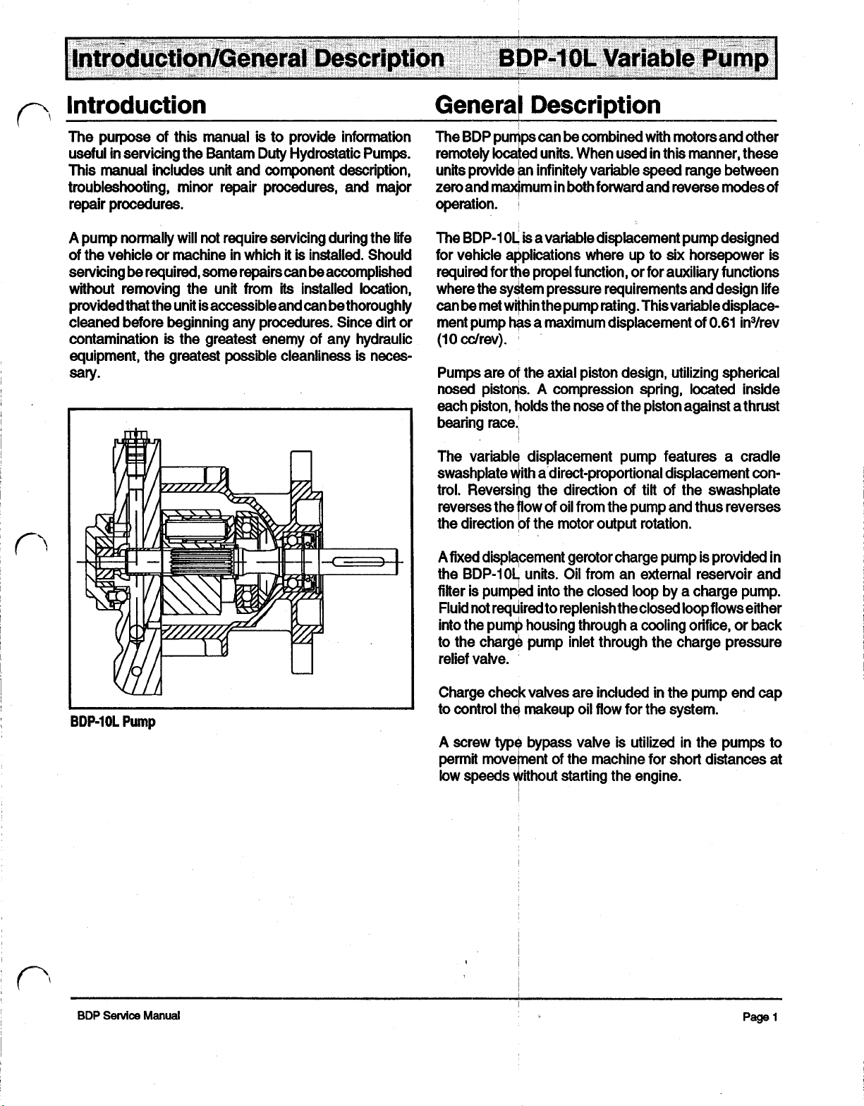
The purpose of this manual
useful
in
servicing the Bantam Duty Hydrostatic Pumps.
This manual includes unit and component description,
troubleshooting, minor repair procedures, and major
repair procedures.
A
pump normally will not require servicing during the lie
of the vehicle or machine in which
servicing be required, some repairscan beaccomplished
without removing the unit from
provided that the unit is accessible and can be thoroughly
cleaned before beginning any procedures. Since dirt or
contamination is the greatest enemy of any hydraulic
equipment, the greatest possible cleanliness is neces-
sary.
is
to provide information
it
is
installed. Should
its
installed location,
The BDP pumps can be combined with motors and other
remotely
units provide an infinitely variable speed range between
zero and maximum in both forward and reverse modes of
operation.
The BDP-1
for vehicle applications where up to
required for the propel function, or for auxiliary functions
where the system pressure requirements and design life
can be met within the pump rating. This variable
ment pump
(10
Pumps are of the
nosed
each piston, holds the
bearing
The variable displacement pump features a cradle
swashplate with a direct-proportional displacement con-
trol. Reversing the direction of tilt of the swashplate
reverses the flow of oil from the pump and thus reverses
the direction of the motor output rotation.
located
cc/rev).
pistons. A compression spring, located inside
units. When used in this manner, these
0L
is
a variable displacement pump designed
six
horsepower
has
a maximum displacement of
axial
piston design, utilizing spherical
nose
of the piston against a thrust
0.61
race.
is
displace-
in³/rev
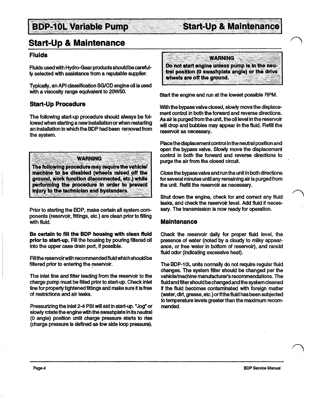
BDP-10L
Pump
A
fixed displacement gerotor charge pump is provided in
the BDP-10L units. Oil from an external reservoir and
fitter is pumped into the closed loop by a charge pump.
Fluid not required to replenish theclosed loop flows either
into the pump housing through a cooling orifice, or back
to the charge pump inlet through the charge pressure
relief valve.
Charge check valves are included in the pump end cap
to control the makeup oil
flow
for the system.
valve is utilized in the pumps to
for short distances at
the engine.
BDP
Service
Manual
Page 5
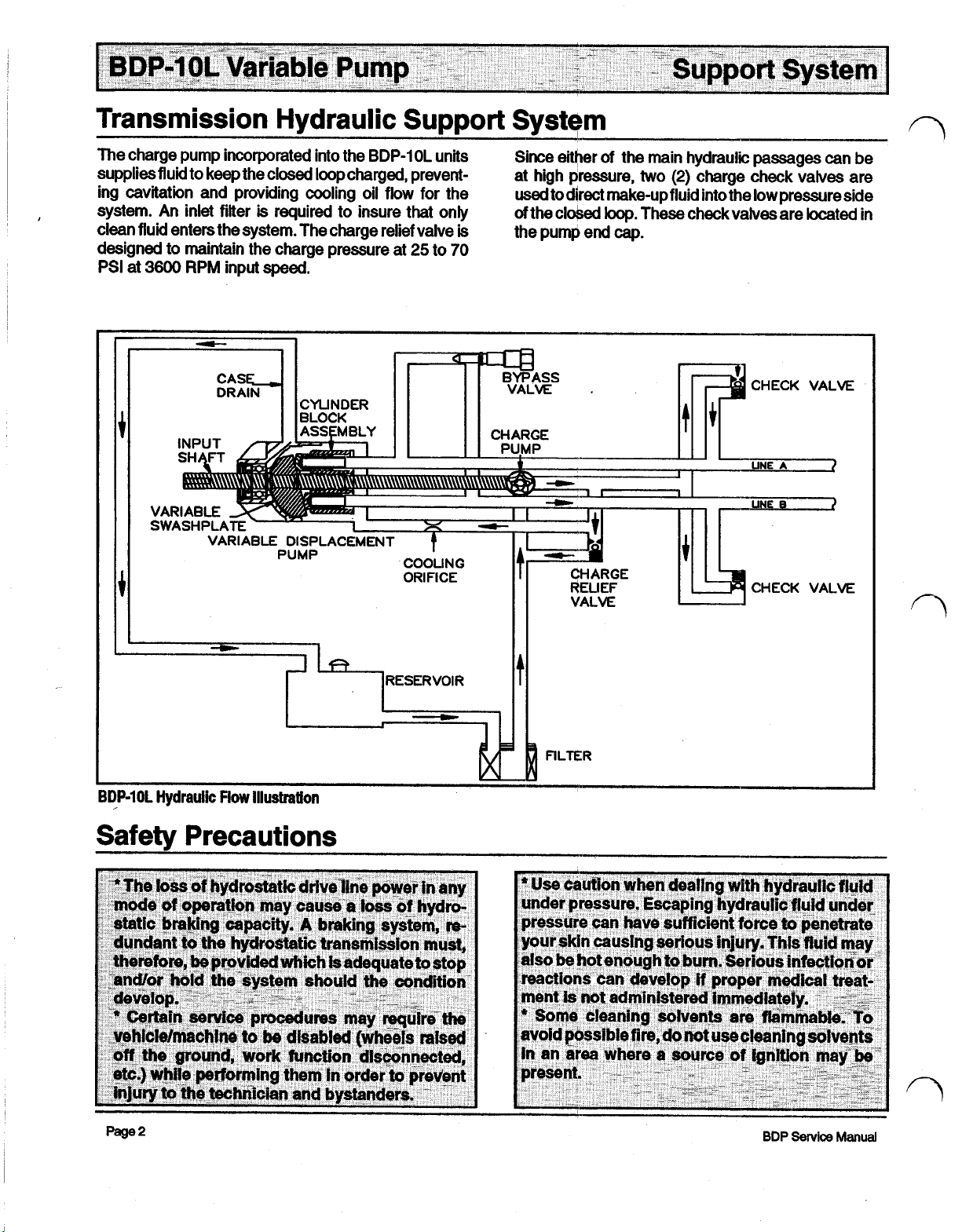
Transmission Hydraulic Support System
The charge pump incorporated into the
supplies fluid to keep the closed loop charged, prevent- at high pressure,
ing cavitation and providing cooling oil flow for the
system. An inlet filter
clean fluid enters the system. The charge relief valve
designed
PSI
at
to
maintain the charge pressure at
3600
RPM
is
required to insure that
input speed.
BDP-1
0L
units Since either
only
is
25
to
70
used
to
direct make-up fluid into the low pressure side
of
the closed
the pump end
of
the main hydraulic passages can be
two
(2)
charge check valves are
loop.
These check valves are located in
cap.
FILTER
Page 6
Controls and Features
Direct Displacement Control
The direct-proportional displacement control
vides a simple method of
swashplate control shaft produces a proportional swashplate movement and change in pump flow and/or direction.
If
difficulties are encountered with the control, inspect the
connection of the control linkage to the swashplate
control
tached.
the neutral
shaft
to insure that the linkage
The vehicle/machine control system determines
position
of the linkage.
control.
Movement of the
(DDC)
is
properly at-
pro-
Charge Pumps
A
fixed displacement gerotor type charge pump is pro-
vided as
Bypass
In
for
engine.
side of the pump/motor circuit to the other, thus allowing
the motor to turn with little resistance.
part
some
applications, it
short
distances at low
A
of
the
BDP-1
0L.
Valve
is
desirable to move the machine
speeds
bypass valve allows oil to be routed from one
without operating the
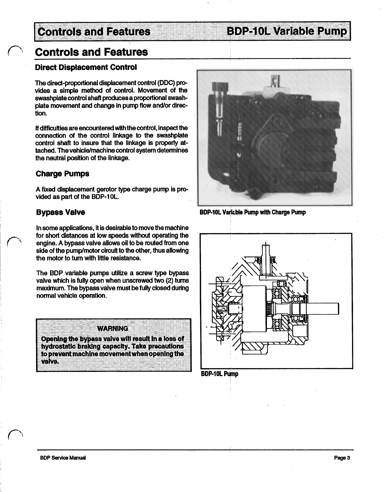
BDP-10L
Variable
Pump
with
Charge
Pump
The
BDP
variable pumps utilize a screw type bypass
valve which is
maximum. The bypass valve must
normal
vehicle operation.
fully
open when unscrewed
be
two
(2)
turns
fully closed during
Page 7
Start-up & Maintenance
Fluids
Fluids used with Hydro-Gear products should
ly selected with assistance from a reputable supplier.
Typically, an API classification SG/CD engine oil is used
with a viscosity range equivalent to
Start-up
The following start-up procedure should always be fol-
lowed when starting a new installatiin or when restarting
an installation in which the BDP had been removed from
the system.
Procedure
20W50.
be
careful-
-
Start the engine and run at the lowest possible RPM.
With the bypass valve closed, slowly move the displace-
ment control in both the forward and reverse directions.
As
will
reservoir
Place thedisplacement control in the neutral position and
open
control in both the forward and reverse directions to
purge the air from the closed circuit.
Close the bypass valve and run the unit in both directions
for several minutes until any remaining air is purged from
the unit.
Shut down the engine, check for and correct any fluid
leaks, and check the reservoir level. Add fluid
Prior to starting the BDP, make certain all system components (reservoir, fittings, etc.) are clean prior to filling
with fluid.
sary. The transmission is now ready for operation.
Maintenance
air
is
purged from the unit, the oil level in the reservoir
drop and bubbles may appear
as
necessary.
the bypass valve. Slowly move the displacement
Refill
the reservoir as necessary.
in
the fluid. Refill the
if
neces-
Be
certain to
prior
to
into the upper case drain
Fill the reservoirwith
filtered prior to entering the reservoir.
The inlet line and filter leading from the reservoir to the
charge pump must
line for properly tightened fittings and make sure it is free
of restrictions and air
Pressurizing the inlet
slowly rotate the engine with the swashplate in its neutral
(0
angle) position until charge pressure starts to rise
(charge pressure is defined as
Page
4
fill
start-up.
the
BDP
housing with clean fluid
Fill the housing by pouring filtered oil
port,
if
possible.
recommended fluid which
be
filled prior to start-up. Check inlet
leaks.
2-4
PSI
will
aid in start-up.
low
side loop pressure).
should
be
"Jog"
or
Check the reservoir daily for proper fluid level, the
presence of water (noted by a cloudy to milky appearance,
or
free water in bottom of reservoir), and rancid
fluid odor (indicating excessive heat).
The BDP-1
changes. The system filter should be changed per the
vehicle/machine manufacturer's recommendations. The
fluid and fitter should
if
the fluid becomes contaminated with foreign matter
(water, dirt, grease, etc.) or if the fluid has been subjected
to temperature levels greater than the maximum recom-
mended.
0L
units normally do not require regular fluid
be
changed and the system cleaned
BDP
Service
Manual
Page 8

Troubleshooting
Chart
Symptom
Vehicle will not attain
maximum speed.
Vehicle
control
Vehicle jerky or operating erratic.
will
not move when vehicle
is
moved.
normal
Probable
Engine not operating at correct
Speed.
Control linkage damaged or
binding.
Bypass valve stuck partially open.
Charge check valve held open.
(Problem in one direction only)
Control linkage damaged or not
connected.
Drive between engine and transmission damaged.
Transmission
Plugged filter.
Inlet air leak.
low
Cause
on fluid.
Suggested
Repair engine governor.
Repair control linkage.
Repair bypass valve.
Remove foreign material from
valve.
Repair or reconnect control
linkage.
Repair drive (replace broken belt,
repair sheared key, repair splined
coupling, etc.)
Refill reservoir. Purge air from
transmission.
Inspect inlet condition and
filter.
Remedy
Vehicle is "sluggish" under load
(operates
OK
on level surface).
Loose
drive belt between engine
and transmission.
Transmission
Large amount of water in
transmission fluid (evaporates
when hot, resulting in low fluid
level).
low
on fluid.
Tension drive belt (replace
necessary).
Refill reservoir. Purge air from
transmission
Drain fluid from reservoir and
unit, replace filter element and
refill with new fluid.
if
necessary.
if
BDP
Service
Manual
Page 9

Minor
Repair
General
Minor repairs may
dures in this section, without voiding the unit warranty.
Cleanliness is a primary means of assuring satisfactory
lie on either new or repaired units. Cleaning
using a clean solvent wash and air drying
adequate.
must
Protect all
from damage and foreign material.
It
is
lubricate all O-rings with clean petroleum jelly prior
assembly.
As
be
kept free of foreign materials and chemicals.
exposed
recommended that all O-rings be replaced. Lightly
be
performed, following the proce-
parts
is
usually
with any precision equipment, all
sealing surfaces and open cavities
by
parts
Fitting/Plug
If
during
the accompanying tables:
r
Case Drain Fitting
(9/16-18 0-Ring)
System
(3/4-16 O-Ring)
Inlet Fitting/Plug
(7/16-20 0-Ring)
Check
to
(9/16- 18 0-Ring)
Bypass Valve
Torques
any plugs are removed from the housing
servicing,
Ports
Valve Plugs
they should be torqued as indicated in
Item
I
I
1
I
I
I
Torque
15-20
15-20
8-10
15-20
7-10
ft.
ft.
ft.
ft.
ft.
or
Ibs.
Ibs.
Ibs.
Ibs
lbs
end
cap
I
I
input
-
-
Input
Page 6
Shaft
Shaft
Seal
Retaining
Seal
Removal
Ring
Removal
Input
Shaft
Seal,
Spacer
Washer,
Shaft
Lip type
ment control shaft of the BDP-1 0L variable pumps. These
seals
unit. However, replacement of these seals generally
requires removal of the pump from the machine.
To
retaining ring from the housing.
Carefully pull the
type tool may be used to grasp the seal and pull
a
seal. Care
bore, shaft sealing surface, or bearing. Once removed,
the seal
Seals
seals
are
used
can
be
replaced without major disassembly of the
replace the pump input shaft
seal
out of the housing bore. A “hook”
slide hammer type puller may be used to re-move the
must
be taken so as not to damage the housing
is
not
reusable.
and
Retaining Ring Removed
on the input shaft and displace-
seal,
first remove the
it
out, or
BDP
Service
Manual
Page 10

Install Input
Shaft
Seal
Note:
Once the pump input shaft
pump block spring may push the shaft partially
the housing.
housing. Internal parts could move
fall into the transmission, requiring major disassembly
of
the unit.
Inspect the dealing area on the shaft for rust, wear or
contamination. Polish the sealing area on the shaft
necessary.
Lubricate the new seal with petroleum jelly.
Wrap the spline or key end of the shaft with thin plastic to
prevent damage to the seal lip during installation.
Slide the seal over the shaft and press it into the housing
bore. Be careful not to damage the seal.
bo
not attempt to pull the shaft
seal
is removed, the
out
of
alignment or
out
out
of
of the
if
Install Input Shaft
Remove Charge Check
Seal
Retaining Ring
Valve
Plugs
Install the
Charge Check
Remove the check valve plug with a
wrench.
Remove the' valve spring and check ball (or poppets)
from the pump end cap.
Inspect the check
the end cap for damage or foreign material.
seal
retaining ring in the housing.
Valves
balls
(or poppets) and mating seats in
1/4"
internal hex
Charge Check
BDP
Service
Manual
Valve
Components
(Poppets
Opt,
Balls
Std.)
Lay the pump on
,
poppets)
Becertain the check ball does not fall into the closed loop
passage. Torque the plug to
over and repeat for the other check valve.
spring, and plug (with O-ring) into the end cap.
P
its
side and reinstall the check ball (or
15-20
ft. lbs.
Turn the unit
Page
7
Page 11

I
Bypass
Unscrew the, bypass valve from the end cap.
Valve
Bypass
Valve
At
Variations
NOTE:
Inspect the valve and mating seat in the end cap for
damage or foreign material.
O-ring and backup ring be replaced.
Reinstall the bypass valve into the end cap. Torque to
10
Some
while others have a cross hole.
ft. lbs.
valves have a
5/8"
It
is recommended that the
hex end
7-
Charge Pump
The charge pump rotation
tion of the charge pump cover on the end cap. The cast
boss
on the Charge pump cover indicates the orientation.
is
determined by the orienta-
Orienting
Orienting Charge Pump
Charge
Pump Cover (CCW
Cover
Rotation)
(CW Rotation)
Make note
the
ing
Using a
screws
Remove the charge pump cover and O-ring.
Remove the charge pump gerotor assembly.
Remove the charge relief valve spring and
of
the correct orientation prior to remov-
charge pump cover.
5
mm
internal hex wrench, remove the
holding
the charge pump cover to the end cap.
ball.
two
(2)
Page
8
BDP
Service
Manual
Page 12

Inspect the gerotor assembly, charge pump cover, and
end
cap for abnormal wear, damage or foreign material.
Inspect the charge relief valve
ball
and spring. Inspect the
charge relief valve seat in the end cap for damage or
foreign material.
Prior to installilng the charge pump, apply a small quantity
of petroleum jelly to the
I.D.,
O.D.,
and side faces
of
the
gerotor assembly
Charge
install
Pump
Components
Gerotor
Assembly
and
Charge
Relief
Valve
Install the charge relief valve
ball
and spring.
Install the charge pump gerotor assembly.
Install the charge pump cover and O-ring. The charge
relief valve spring must enter the recess
in
the cover.
Install the charge pump cover screws. Toque each
screw to
7-1 0 ft.
Ibs.
BDP
Service
Manual
~
Page
9
Page 13

Major
Repair
General
The procedures on the following pages are for the
complete disassembly and reassembly (Major Repair) of
the BDP-1 0L variable pump.
Again, cleanliness is a primary means of assuring satis-
factory hydraulic unit life on either new or repaired units.
Cleaning parts by using a clean solvent wash and air
drying is usually adequate.
ment,
all
parts must be kept free of foreign materials and
chemicals. Protect all exposed sealing surfaces and
open cavities
During reassembly of the pump all surfaces which have
relative motion between
filmofclean
will
assure that these surfaces will
start-up.
It
is recommended that all O-rings and gaskets be re-
placed. Lightly lubricate all O-rings with clean petroleum
jelly prior to assembly.
be cleaned prior to installing new gaskets.
from
damage and foreign material.
oil or a lubricant such as petroleum jelly. This
As
with any precision equip-
two
parts must be coated with a
be
lubricated during
All
gasket sealing surfaces must
Remove
End
Cap
from
Housing
Disassembly Procedures
for
Variable
Pump
Prior to performing Major Repairs on the pump, remove
the external components
Repair" section of this manual. These include the following:
Bypass valve
Charge Check
Charge Pump
Lay the unit on its
remove the four
the pump housing.
The internal springs should separate the end cap from
the housing. Remove the end cap from the housing.
Valves
side.
(4)
as
described in the 'Minor
Using a 6 mm internal hexwrench,
screws which retain the end cap to
emove
Remove the gasket and
housing.
Remove the pump cylinder block
Remove the pump cylinder blockspring and washerfrom
the pump shaft.
Gasket
and
Aligning Pins
two
(2)
alignment pins from the
kit
from the pump shaft.
Page
10
BDP
Service
Manual
Page 14

Remove the thrust bearing from the swashplate.
Remove the pump swashplate from the housing.
Remove the swashplate cradle bearings from the
housing.
Remove the slot guide block from the displacement
control shaft.
Remove Pump Cylinder Block
Swashplate and
Remove
from Housing
Input
Cradle
Shaft
Retaining Ring,
Kit,
Block Spring and Washer,
Bearings from Housing
Seal
and
Input
Shaft
Remove the input shaft seal retaining ring.
Carefully pull the input shaft
A
hook may
type puller may
be taken
sealing surface
reusable.
Remove the bearing spacer washer.
Remove the pump shaft and bearing assembly from the
housing.
be
used to pry theseal
be
used to remove
so
as
not to damage the housing bore, shaft
or
bearing. Once removed, theseal is not
seal
out of the housing bore.
out,
or a slide hammer
the
seal. Care must
Remove Bearing
BDP
Service
from
Manual
Input
Shaft
Remove the outer bearing retaining ring (and washer,
used)
and press the shaft out of the bearing.
NOTE:
most
An
inner
bearing
shafts. Remove
retaining
it
from
the
ring
shaft if
is used
necessary.
Page
if
on
11
Page 15

If
the pump block spring retaining ring requires replace-
ment, remove
it
from the pump shaft.
Cylinder
Block
Kit
Components
Reconditioning and Replacement of Parts
After
disassembly,
in a suitable solvent. Replace all O-rings, gaskets and
shaft seals.
Inspect all parts for damage, nicks or unusual wear
patterns. Replace all parts having unusual or excessive
wear or discoloration.
Inspect the
splines. Polish the sealing areas on the shafts if
sary.
Replace any
all parts should be
seal
surfaces, bearing surfaces and
worn
or damaged parts.
thoroughly
cleaned
shaft
neces-
Remove the displacement control shaft
housing. Care must be taken
so
seal
out
of the
as not to damage the
housing bore.
is
The pump shaft bushing
should
not
be
removed.
The running surfaces of the cylinder blocks
and free from scratches.
on the running surface of the cylinder block or end
pressed into the end cap and
MUST
be flat
If
scratches or wear are found
cap,
polish or replace the parts. When polishing these sur-
faces, up to
0.0004
in. may be removed.
If
this is not
sufficient to obtain a flat surface, free of scratches, the
part
should be replaced.
I
Install
Page
12
Displacement
Control
Shaft
Assembly Procedures for Variable Pump
Clean and lightly oil parts prior to assembly
pump. Be sure to toque all threaded parts to recom-
mended torque levels.
Install the displacement control shaft into the housing.
J
of
the variable
BDP
Service Manual
Page 16

If
the block spring retaining ring was removed from the
pump shaft, install a new retaining ring onto the shaft.
(if
Install a new inner bearing retaining ring
used) onto the
pump shaft. Press the bearing onto the shaft. Install the
washer
(if
used) and a new outer bearing retaining ring.
Install Input
install
Bearing
In
Shaft
Spacer
Washer
NOTE:
Do
not stretch or
deform
the retaining ring.
Install, the pump shaft and bearing assembly into the
housing.
Install the bearing spacer washer.
Wrap the spline or key end of pump drive shaft with thin
plastic to prevent damage to the seal lip during installation. Lubricate the new pump shaft seal with petroleum
jelly.
Install Input
Shaft
Seal
Install Input
Shaft
Retaining Ring
Seal
Slide the seal over the shaft and press it into the housing
bore. Be careful not to damage seal.
Install the retaining ring.
Page
13
Page 17

Install the swashplate cradle bearings into the housing,
making sure they are located on the cast-in pins in the
housing.
Install the slot guide blockonto the displacement control
shaft.
Install Cradle Bearings and
Swashplate
Kit
Components
Guide
Block
Install the Swashplate into the housing. The slot on the
swashplate must engage the guide block on the displace-
ment control shaft. Use
magnet to
hold
the guide block in position while installing
a
tool such as a screwdriver or
the swashplate.
Hold
the swashplate in position and measure the side
play
of
the displacement control shaft using a dial indicator or depth gauge. Using a suitable sleeve, press the
control shaft bearing into the housing until the control
shaft end play is between
0.020
and
0.060
in.
Install Swashplate,
Page
14
Thrust
Washer
and
Block
Spring
Install the thrust washer and pump cylinder block spring
onto the pump shaft.
BDP
Service
Manual
Page 18

Install the springs, piston washers and pistons into the
cylinder block. The pistons must move freely in their
bores.
With the pump swashplate in the "neutral"
position and ;he pump housing laying on
the pump cylinder block
Check that the piston springs are centered in the cylinder
block bores.
screwdriver.
housing.
(0
angle)
its
side, install
kit
onto the pump shaft in the
If
necessary, position them with a small
Cylinder
Install
Pump
Block
Kit
Components
Cylinder Block
Kit
Install the two
(2)
aligning pins, and install a new end cap
gasket onto the housing.
Lubricate the running surfaces
of
the end
cap
and
cylinder blocks. Position the housing with the housing
opening UP,
When the end
springs
3/8
in.
Install the four
variable pump housing. Toque the screws evenly to
20 ft.
Rotate the shaft to assure
properly assembled, minimal torque should
to
turn the shaft.
will
Ibs.
and
install the end cap onto the housing.
cap
is properly installed, the internal
hold
it
away from the housing approximately
(4)
screws which retain the end cap to the
correct
assembly. When
be
15-
required
Install
BDP
Service
End
Cap
Manual
Wrap the end, of the displacement control shaft with thin
plastic to prevent damage to the
seal
lip during installation. Lubricate the new displacement control shaft seal
with petroleum jelly. Slide the
it
press
into the housing bore. Be careful not to damage
seal
over the shaft and
the seal.
Assemble the following components as described in the
"Minor Repair” section of this manual:
Charge Pump
Charge Check Valves
Bypass
Valve
Page
15
Page 19

No.
Description
Housing
1
seal-Up
2
End Cap Jut
End
Cap
Kit
Part
No.
2513017
2518016
1
Part
No.
Description
17
Ring,
Back
cump
-
Ball
Up
Shaft -
18
19 1
Bearing
1
No.
9006110-0120
2003020
2003073
2003043
Qty
1
1
Page
16
Charge Pump
Gerotor
I
11
Assembly
Valve
Kit
I
251008 Check
2510027
1
1
1
1
I
Spring
Washer
Washer
-
Piston
-
Piston
-
Block
Thrust
251 001 1
8
251 301
BDP
Service
Manual
Page 20

Variation
Chart
CHECK
Trunnion
Side Trunnion
I
I
2510008
MODEL NO.
BDP-1 0L-1 10 2003020 2513029 251 0008
BDP-10L-1
I I
I
I
Shaft
2003020
#
VALVE
I
I
BYPASS
KIT
2513029
VALVE KITS
Opp.
251 0008
251 0008
251 0008
251 0008
251 0008
251 0027
251 0008
251 0008
251 0027
251 0027
251
251 0027
251
251 0027
0008
0008
ROTATION
CW
CCW
CW
CCW
CCW
CCW
CCW
CCW
CCW
CCW
CW
CW
CW
CW
251 0008
2510008
CW
CCW
BDP
Service
Manual
Page
17
Page 21

A
World Leader in
Hydro-Gear is a leader in engineered products designed specifically for the turf care industry with a wide range of hydrostatic
transaxles, transmissions and pumps. Hydro-Gear and its associate companies provide complete worldwide service parts,
repair, and technical assistance.
Turf
Care Transmission
Products
210-2510L
ZT
Drive
Axles
210-101
OS
Transaxles
Bantam
Duty
Pumps
I
HYDRO-GEAR, 1411
Phone: (217)728-2581; FAX (21 7)72-7665
S.
Hamilton,
Sullivan,
IL
61951
 Loading...