

Page 1
MODEL NO. 30301 - 220000001 & UP
MODEL NO. 30301TC - 220000001 & UP
MODEL NO. 30302 - 220000001 & UP
MODEL NO. 30302TC - 220000001 & UP
FORM NO. 3326-938
OPERATOR'S
MANUAL
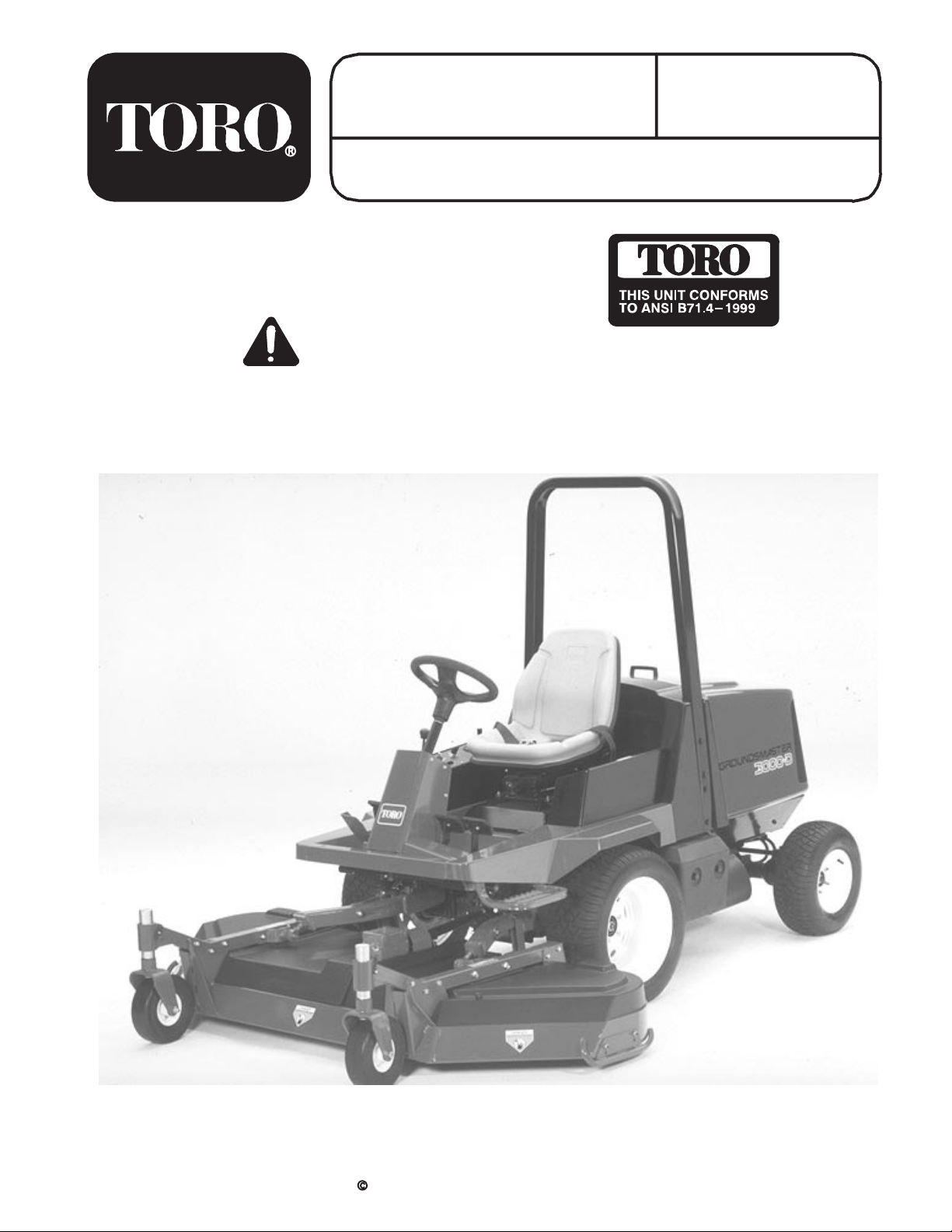
GROUNDSMASTER® 3000-D
2 & 4 WHEEL DRIVE TRACTION UNITS
To understand this product, and for safety and
optimum performance, read this manual before
starting the engine. Pay special attention to SAFETY
INSTRUCTIONS highlighted by this symbol.
It means CAUTION, WARNING or DANGER personal safety instruction. Failure to comply with
the instruction may result in personal injury.
The GROUNDSMASTER 3000-D conforms to the
B71.41999 specifications of the American National
Standards Institute's safety standards for riding
mowers: thus, TORO proudly displays the ANSI
safety seal.
The TORO COMPANY - 2001
Page 2

FOREWORD
This operator's manual has instructions on safety, proper set-up and operation, adjustments and maintenance.
Therefore, anyone involved with the product, including the operator, should read and understand this manual.
Major sections are:
- Safety Instructions
- Specifications
- Set-up Instructions
- Before Operating
This manual emphasizes safety, mechanical and general product information. DANGER, WARNING and
CAUTION identify safety messages. Whenever the triangular safety alert symbol appears, understand the safety
message that follows. For complete safety instructions, read pages 4-6. IMPORTANT highlights special
mechanical information and NOTE emphasizes general product information worthy of special attention.
Diesel engine exhaust and some of its
constituents are known to the State of
California to cause cancer, birth defects,
or other reproductive harm.
- Know Your Controls
- Operating Instructions
- Maintenance
- Schematics
Whenever you have questions or need service, contact your local authorized Toro Distributor. In addition to having a
complete line of accessories and professional turf care service technicians, the distributor has a complete line of
genuine TORO replacement parts to keep your machine operating properly. Keep your TORO all TORO. Buy
genuine TORO parts and accessories.
IDENTIFICATION AND ORDERING
MODEL AND SERIAL NUMBER
The model and serial number is on a plate that is
mounted on the left side of operator platform behind
footrest. Use model and serial number in all
correspondence and when ordering parts.
To order replacement parts from an authorized TORO
Distributor, supply the following information:
1. Model and serial numbers of the machine.
2. Part number, description and quantity of parts
desired.
Note: Do not order by reference number if a parts
catalog is being used; use the part number.
2
Page 3

TABLE OF CONTENTS
IDENTIFICATION & ORDERING 2. . . . . . . . . . . . . .
Model And Serial Number 2. . . . . . . . . . . . . . . .
SAFETY INSTRUCTIONS 4. . . . . . . . . . . . . . . . . . . .
SAFETY INSTRUCTIONS & DECALS 7. . . . . . . . .
SPECIFICATIONS 9. . . . . . . . . . . . . . . . . . . . . . . . . .
LOOSE PARTS CHART 10. . . . . . . . . . . . . . . . . . . . .
SETUP INSTRUCTIONS 11. . . . . . . . . . . . . . . . . . .
Install Front and Rear Wheels 11. . . . . . . . . . . .
Install Steering Wheel 11. . . . . . . . . . . . . . . . . . .
Install Roll Bar 11. . . . . . . . . . . . . . . . . . . . . . . . . .
Grease Traction Unit 11. . . . . . . . . . . . . . . . . . . .
BEFORE OPERATING 12. . . . . . . . . . . . . . . . . . . . .
Check Engine Oil 12. . . . . . . . . . . . . . . . . . . . . . .
Check Cooling System 12. . . . . . . . . . . . . . . . . .
Fill Fuel Tank 12. . . . . . . . . . . . . . . . . . . . . . . . . . .
Check Hydraulic Fluid 13. . . . . . . . . . . . . . . . . . .
Check Rear Axle Lubricant 13. . . . . . . . . . . . . . .
Check Tire Pressure 14. . . . . . . . . . . . . . . . . . . .
Check Torque Of Wheel Nuts 14. . . . . . . . . . . .
KNOW YOUR CONTROLS 15. . . . . . . . . . . . . . . . . .
OPERATING INSTRUCTIONS 16. . . . . . . . . . . . . . .
Starting And Stopping 16. . . . . . . . . . . . . . . . . . .
Priming Fuel System 16. . . . . . . . . . . . . . . . . . . .
Checking Interlock Switches 16. . . . . . . . . . . . .
Pushing or Towing Traction Unit 17. . . . . . . . . .
Operating Characteristics 17. . . . . . . . . . . . . . . .
LUBRICATION 19. . . . . . . . . . . . . . . . . . . . . . . . . . . .
Greasing Bearings And Bushings 19. . . . . . . . .
DAILY MAINTENANCE CHECKLIST 20. . . . . . . . .
Page Page
MAINTENANCE SCHEDULE 21. . . . . . . . . . . . . . . .
AIR CLEANER MAINTENANCE 22. . . . . . . . . . . . .
General Air Cleaner Maintenance 22. . . . . . . . .
Servicing Air Cleaner 22. . . . . . . . . . . . . . . . . . . .
ENGINE MAINTENANCE 23. . . . . . . . . . . . . . . . . .
Engine Oil And Filter 23. . . . . . . . . . . . . . . . . . . .
Fuel System 23. . . . . . . . . . . . . . . . . . . . . . . . . . .
Engine Cooling System 24. . . . . . . . . . . . . . . . .
Engine Belts 24. . . . . . . . . . . . . . . . . . . . . . . . . . .
Service Spark Arrester Muffler 25. . . . . . . . . . . .
HYDRAULIC MAINTENANCE 26. . . . . . . . . . . . . . .
Changing Hydraulic System Oil and Filter 26. .
Checking Hydraulic Lines And Hoses 27. . . . .
Hydraulic System Test Port 27. . . . . . . . . . . . . .
Adjusting Traction Drive Pedal Linkage 27. . . .
HYDRAULIC SCHEMATIC 28. . . . . . . . . . . . . . . . . .
BRAKE MAINTENANCE 29. . . . . . . . . . . . . . . . . . . .
Adjusting Service Brakes 29. . . . . . . . . . . . . . . .
AXLE MAINTENANCE 30. . . . . . . . . . . . . . . . . . . . . .
Changing Rear Axle Lubricant 30. . . . . . . . . . . .
Rear Wheel Toe-in 30. . . . . . . . . . . . . . . . . . . . .
ELECTRICAL MAINTENANCE 31. . . . . . . . . . . . . .
Battery Care 31. . . . . . . . . . . . . . . . . . . . . . . . . . .
Fuses 31. . . . . . . . . . . . . . . . . . . . . . . . . . . . . . . . .
ELECTRICAL SCHEMATIC 32. . . . . . . . . . . . . . . . .
PREPARATION FOR SEASONAL STORAGE 33.
NOTES 34. . . . . . . . . . . . . . . . . . . . . . . . . . . . . . . . . . .
WARRANTY Back Cover. . . . . . . . . . . . . . . . . . . . . . . . .
3
Page 4

SAFETY INSTRUCTIONS
This machine meets or exceeds the B71.4 1999
specifications of the American National Standards
Institute, in effect at time of production, when 40 lbs. of
ballast is added to the rear wheel.
Note: The addition of attachments made by other
manufacturers that do not meet American National
Standards Institute certification will cause noncompliance
of this machine.
Improper use or maintenance by the operator or owner
can result in injury. To reduce the potential for injury,
comply with these safety instructions and always pay
attention to the safety alert symbol, which means
CAUTION, WARNING, or DANGER—“personal
safety instruction.” Failure to comply with the
instruction may result in personal injury or death.
Safe Operating Practices
The following instructions are from ANSI standard
B71.4—1999.
Training
• Read the Operator ’s Manual and other training
material. If the operator(s) or mechanic(s) can not read
English it is the owner’s responsibility to explain this
material to them.
• Become familiar with the safe operation of the
equipment, operator controls, and safety signs.
• All operators and mechanics should be trained. The
owner is responsible for training the users.
• Never let children or untrained people operate or
service the equipment. Local regulations may restrict
the age of the operator.
• The owner/user can prevent and is responsible for
accidents or injuries occurring to himself or herself,
other people or property.
Preparation
• Evaluate the terrain to determine what accessories and
attachments are needed to properly and safely perform
the job. Only use accessories and attachments
approved by the manufacturer.
• Wear appropriate clothing including hard hat, safety
glasses and ear protection. Long hair, loose clothing or
jewelry may get tangled in moving parts.
• Inspect the area where the equipment is to be used and
remove all objects such as rocks, toys and wire which
can be thrown by the machine.
4
• Use extra care when handling gasoline and other fuels.
They are flammable and vapors are explosive.
– Use only an approved container.
– Never remove gas cap or add fuel with engine
running. Allow engine to cool before refueling. Do
not smoke.
– Never refuel or drain the machine indoors.
• Check that operator ’s presence controls, safety
switches and shields are attached and functioning
properly. Do not operate unless they are functioning
properly.
Operation
• Never run an engine in an enclosed area.
• Only operate in good light, keeping away from holes
and hidden hazards.
• Be sure all drives are in neutral and parking brake is
engaged before starting engine. Only start engine from
the operator ’s position. Use seat belts if provided.
• Slow down and use extra care on hillsides. Be sure to
travel in the recommended direction on hillsides. Turf
conditions can affect the machine’s stability. Use
caution while operating near drop-offs.
• Slow down and use caution when making turns and
when changing directions on slopes.
• Never operate with guards not securely in place. Be
sure all interlocks are attached, adjusted properly, and
functioning property.
• Do not change the engine governor setting or
overspeed the engine.
• Stop on level ground, raise the cutting unit, disengage
drives, engage parking brake (if provided), shut off
engine before leaving the operator’s position for any
reason.
• Stop equipment and inspect the machine after striking
objects or if an abnormal vibration occurs. Make
necessary repairs before resuming operations.
• Keep hands and feet away from the cutting units.
• Look behind and down before backing up to be sure of
a clear path.
• Never carry passengers and keep pets and bystanders
away.
• Slow down and use caution when making turns and
crossing roads and sidewalks. Stop reels if not
mowing.
• Do not operate the mower under the influence of
alcohol or drugs
Page 5

SAFETY INSTRUCTIONS
• Use care when loading or unloading the machine into a
trailer or truck
• Use care when approaching blind corners, shrubs,
trees, or other objects that may obscure vision.
Maintenance and Storage
• Disengage drives, raise the cutting units, set parking
brake, stop engine and remove key and disconnect
spark plug wire. Wait for all movement to stop before
adjusting, cleaning or repairing.
• Clean grass and debris from cutting units, drives,
mufflers, and engine to help prevent fires. Clean up oil
or fuel spillage.
• Let engine cool before storing and do not store near
flame.
• Shut off fuel while storing or transporting. Do not store
fuel near flames or drain indoors.
• Park machine on level ground. Never allow untrained
personnel to service machine.
• Use jack stands to support components when required.
• Carefully release pressure from components with
stored energy.
• Disconnect battery before making any repairs.
Disconnect the negative terminal first and the positive
last. Reconnect positive first and negative last.
• Use care when checking the blades. Wear gloves and
use caution when servicing them.
• Keep hands and feet away from moving parts. If
possible, do not make adjustments with the engine
running.
• Charge batteries in an open well ventilated area, away
from spark and flames. Unplug charger before
connecting or disconnecting from battery. Wear
protective clothing and use insulated tools.
• Keep all parts in good working condition and all
hardware and hydraulic fittings tightened. Replace all
worn or damaged decals.
Operation
• Know how to stop the engine quickly.
• Always wear substantial shoes. Do not operate the
machine while wearing sandals, tennis shoes, or
sneakers.
• Wearing safety shoes and long pants is advisable and
required by some local ordinances and insurance
regulations.
• Handle fuel carefully. Wipe up any spills.
• Check the safety interlock switches daily for proper
operation. If a switch should fail, replace the switch
before operating the machine. After every two years,
replace all three interlock switches in the safety
system, regardless if they are working properly or not.
• Using the machine demands attention. To prevent loss
of control:
– Do not drive close to sand traps, ditches, creeks, or
other hazards.
– Reduce speed when making sharp turns. Avoid
sudden stops and starts.
– Watch out for traffic when near or crossing roads.
Always yield the right-of-way.
– Apply the service brakes when going downhill to
keep forward speed slow and to maintain control of
the machine.
• Raise the cutting unit when driving from one work
area to another.
• Do not touch the engine, muffler, or exhaust pipe
while the engine is running or soon after it has stopped
because these areas could be hot enough to cause
burns.
• If a cutting unit strikes a solid object or vibrates
abnormally, stop immediately, turn the engine off, wait
for all motion to stop, and inspect the machine for
damage. A damaged blade must be replaced before
operation is continued.
Toro Mower Safety
The following list contains safety information specific to
Toro products or other safety information that you must
know that is not included in the ANSI standards.
This product is capable of amputating hands and feet and
throwing objects. Always follow all safety instructions to
avoid serious injury or death.
Use of this product for purposes other than its intended
use could prove dangerous to user and bystanders.
• Traverse slopes carefully. Do not start or stop suddenly
when traveling uphill or downhill.
• The operator must be skilled and trained in how to
drive on hillsides. Failure to use caution on slopes or
hills may cause loss of control and cause the vehicle to
tip or roll, possibly resulting in personal injury or
death.
• If the engine stalls or loses headway and cannot make
it to the top of a slope, do not turn the machine around.
Always back slowly, straight down the slope.
5
Page 6

SAFETY INSTRUCTIONS
• When a person or pet appears unexpectedly in or near
the mowing area, stop mowing. Careless operation,
combined with terrain angles, ricochets, or improperly
positioned guards can lead to thrown object injuries.
Do not resume mowing until the area is cleared.
• Whenever the machine is left unattended, make sure
the cutting unit is disengaged, the key is removed from
the ignition switch, and the parking brake is set.
Maintenance and Storage
• Make sure all hydraulic line connectors are tight and
all hydraulic hoses and lines are in good condition
before applying pressure to the system.
• Keep your body and hands away from pin hole leaks
or nozzles that eject hydraulic fluid under high
pressure. Use paper or cardboard, not your hands, to
search for leaks. Hydraulic fluid escaping under
pressure can have sufficient force to penetrate the skin
and cause serious injury.
• Before disconnecting or performing any work on the
hydraulic system, all pressure in the system must be
relieved by stopping the engine and lowering the
cutting units and attachments to the ground.
• Check all fuel lines for tightness and wear on a regular
basis. Tighten or repair them as needed.
• Periodically inspect the roll bar and roll bar mounting.
Repair, as necessary. Do not weld, cut, drill, or modify
roll bar in any manner.
• If the engine must be running to perform a
maintenance adjustment, keep hands, feet, clothing,
and any parts of the body away from the cutting units,
attachments, and any moving parts, especially the
screen at the side of the engine. Keep everyone away.
• Do not overspeed the engine by changing governor
settings. To ensure safety and accuracy, have an
Authorized Toro Distributor check the maximum
engine speed with a tachometer.
• The engine must be shut off before checking the oil or
adding oil to the crankcase.
• If major repairs are ever needed or if assistance is
desired, contact an Authorized Toro Distributor.
• To make sure of optimum performance and continued
safety certification of the machine, use only genuine
Toro replacement parts and accessories. Replacement
parts and accessories made by other manufacturers
could be dangerous, and such use could void the
product warranty.
6
Page 7
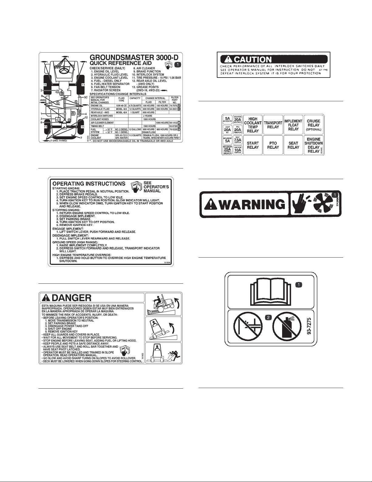
SAFETY AND INSTRUCTION DECALS
The following safety and instruction decals are mounted on the traction unit. If any decal becomes damaged or
illegible, install a new decal. Part numbers are listed below or in your parts catalog.
Part No. 67–1710
Part No. 93–5934
1. See Operator’s Manual
Part No. 93–5932
Part No. 93–5930
Part No. 93–5921–Model 30301
Part No. 93–5622–Model 30302
Part No. 77–3100
1. Keep hands away from
fan blades
Part No. 93–7275
1. Read and understand
Operator’s Manual
2. Do not prime engine or
use starting fluid
7
Page 8
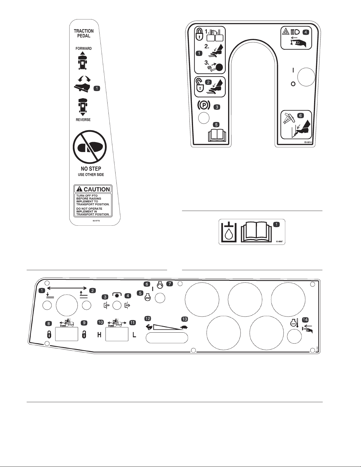
Part No. 92–5772
1. Press down on front of
traction pedal to go
forward; rear of pedal to
go in reverse
Part No. 95–0814
1. To lock parking
brake–Latch pedals
together, apply brake
pedals and pull up on
knob
2. To unlock parking
brake–step on brake
pedals
3. Locks the parking brake
4. Optional light switch
5. Press down on lever to
adjust steering wheel
position
6. Read the operator’s
manual
Part No. 93-8067
1. Read the operator’s manual for the correct hydraulic oil level.
1. Lower cutting unit
2. Raise cutting unit
3. PTO–On
4. PTO–Off
8
Part No. 93-5425
5. Engine–Stop
6. Engine–On
7. Engine–Off
8. Optional Cruise control–On
9. Optional Cruise control–Off
10. Hi–Lo speed–On
11. Hi–Lo speed–Off
12. Throttle–Slow
13. Throttle–Fast
14. Temperature reset button
Page 9

SPECIFICATIONS
Engine: Peugeot TUD5, 4 cylinder, 4 cycle, in-line,
over-head cam, liquid cooled diesel engine with
centrifugal water pump. Available power, 36 hp at 2625
RPM. 1.5 liter displacement, governed to a maximum
speed of 2780 RPM. Compression ratio 23.5:1. Glow
plugs controlled by pre/post heat relay. Oil capacity
4.75 quart (4.5 liters) with oil filter. 12 volt type 4 starter
motor with integral solenoid. 70 amp type 7 alternator
with integral regulator.
Fuel Tank Capacity: 12 gallons diesel fuel
Radiator : Rear mount industrial radiator with tube and
fin construction: 4 rows, 5 fins per inch. Thermally
stable water cooled hydrostatic system regulates
operating temperature. Separate degassing bottle to
remove air from cooling system fluid. System capacity
approximately 11.5 quarts (10.9 liter).
Controls: Hand operated throttle, PTO switch,
hydraulic lift/lower/counterbalance of implement,
ground speed high/low range switch, ignition switch.
Foot operated tilt steering locking lever, traction pedal,
steering/parking brake pedals.
Gauges and Diagnostics: Gauge package includes
fuel gauge, engine coolant temperature gauge, and
hour meter. Indicator light for high engine coolant
temperature, low engine oil pressure, alternator, low
engine coolant level, water in fuel, glow plugs.
Electrical Features: 12 volt automotive type electrical
system. 650 cold cranking amp battery performance at
00F. Dash mounted ignition switch. 70 amp alternator.
PTO, seat and traction interlock switches.
Transaxle/PTO: Sauer-Sundstrand integrated
hydrostatic transaxle (IHT-M15) incorporating the
hydrostatic transmission, mechanical gearbox,
differential, drive axle, power-take-off (PTO) system,
implement hydraulic system pump and reservoir in a
single component. Variable speed, axial piston,
hydrostatic U-type transmission: gear type charge
circuit hydraulics with filtration provides hydraulic flow
for power steering and implement lift. Approximately
12 quart oil capacity. Single foot pedal control of
forward/reverse ground speed. Two speed axle with
"shift on the fly" speed range selection. 4wd is
mechanically driven from front axle by a universal shaft.
Double overrunning clutch provides 4wd function in
forward and reverse preventing rear tire scuffing in
turns. Both 2wd and 4wd have the same turning radius.
Optional cruise control available.
Implement Lift: Twin hydraulic lift cylinders (2.5" bore
x 3.5" stroke) provide lift, lower and counterbalance of
implement via electrically actuated hydraulic control
manifold.
Steering: Eaton Series 2 steering control unit with
power beyond. Steering valve controls single steering
cylinder. Steering system is single tie-rod type which
provides identical steering performance on both two
and four wheel drive versions. Tilt steering wheel with
single lever control. 14" diameter steering wheel.
Ground Speed
Low speed - 0-8 mph, infinitely variable
High speed - 0-15 mph, infinitely variable
Clearance
Front ground clearance - 8.25 inches
Rear ground clearance - 2wd : 6.00 inches
4wd : 4.75 inches
Tires/Wheels/Pressures
Two front traction drive tires
Models 30301 TC and 30302 TC - 25 x10.5-15 turf
tread, 6 ply rating.
Models 30301 and 30302 - 24 x13-12 turf tread, 4 ply
rating.
Two rear steering tires
Models 30301 TC and 30302 TC - 20 x 8-10, turf
tread, 6 ply rating.
Models 30301 and 30302 - 18 x 8.50-10, turf tread,
4 ply rating.
Tire pressure - 15 psi
Brakes: Individual mechanical caliper disc brakes
provide both independent application for steering
assist and combined application for parking brake
function. Dynamic braking through the hydrostatic
traction drive.
Seat: Deluxe high back seat. Optional seat suspension
kit, Model 30395, or deluxe adjustable suspension kit,
Model 30396.
Storage: Toolbox with cover located to the left of the
seat base. Beverage holder integral to toolbox cover.
Operator manual storage tube furnished for
attachment to seat frame.
Weight: 2wd - 1930lbs (875kg)
4wd - 2030lbs (920kg)
Wheel Base: 55 inches
Tread Width: 53 inches
Specifications and design subject to change without notice.
9
Page 10

LOOSE PARTS CHART
Note: Use this chart as a checklist to assure all parts necessary for assembly have been received. Without these
parts, total setup cannot be completed. Some parts may have already been assembled at factory.
DESCRIPTION QTY. USE
Wheel nut 10 Mount Rear Wheels
Wheel 2
Wheel nut 10 Mount Front Wheels
Wheel 2
Steering Wheel 1
Foam Seal 1
Nut 1 Install Steering Wheel
Washer 1
Cap 1
Seat Belt 1
Bolt 2 Install Seat Belts to Seat. (Model 30302 only)
Lockwasher 2
Roll Bar (ROPS) 1
Bar Assembly 2
Bolt 8 Install Roll Bar. (Model 30302 only)
Flat washer 8
Operator's Manual 2
Parts Catalog 1
Registration Card 1 Fill out and return to Toro
Hydraulic Oil Filter (94-3951) 1 Change after 200 hours
10
Page 11
SET-UP INSTRUCTIONS
INSTALL FRONT & REAR WHEELS
1. Mount wheels and torque mounting nuts to 7580
ft-lbs (102108 Nm).
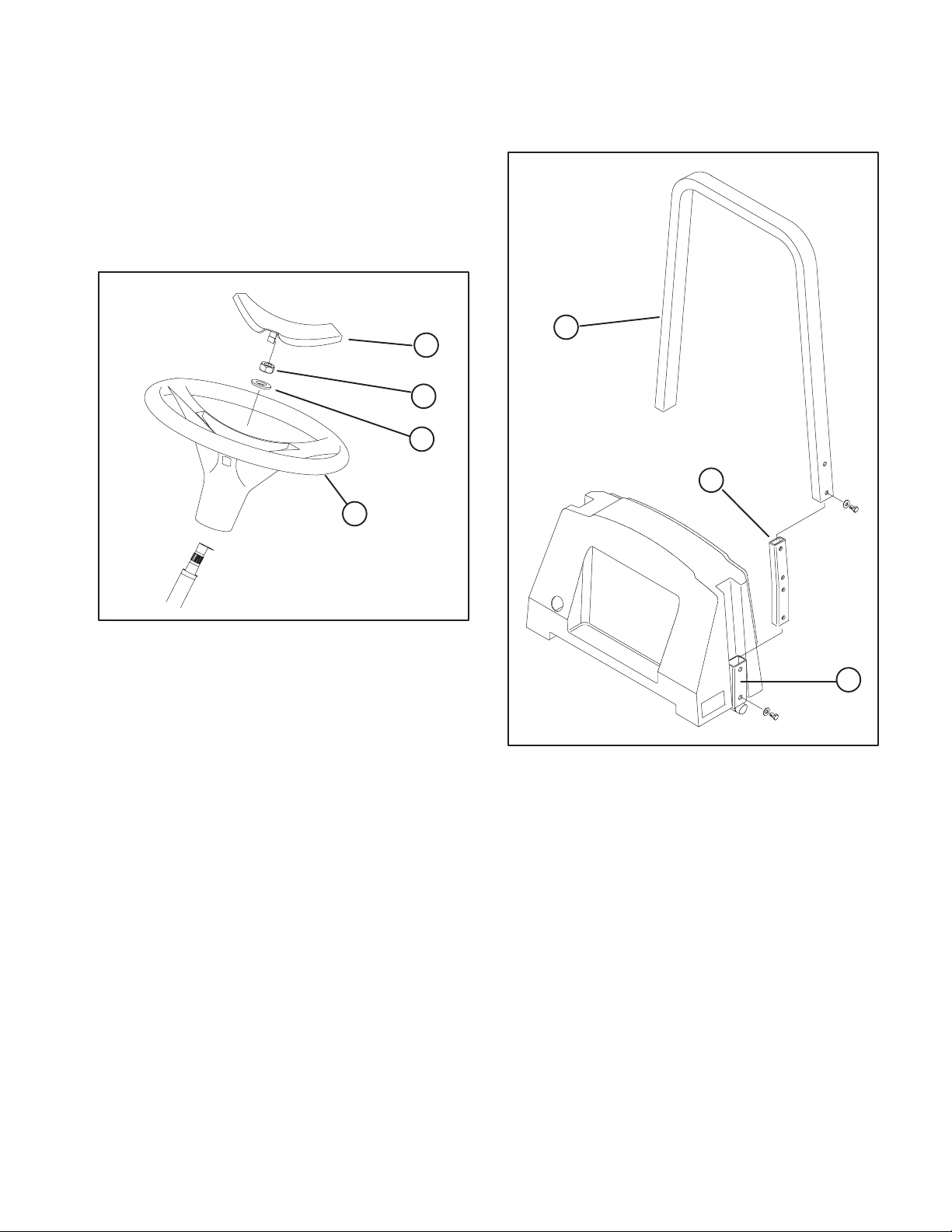
INSTALLING STEERING WHEEL (Fig. 1)
1. Move rear wheels so they point straight ahead.
2. Slide steering wheel assembly onto steering shaft.
4
3
2
1
3. Loosely secure bar assembly to frame holder with
(4) bolts and flat washers (Fig. 2).
4. Tighten all fasteners to 100 ft-lb..
1
2
Figure 1
1. Steering Wheel
2. Flat Washer
3. Nut
4. Cap
3. Secure steering wheel to shaft with flat washer and
nut. Tighten nut it to 10-15 ft-lb.
4. Install cap on steering wheel.
INSTALL ROLL BAR (Fig. 2)
Model 30302 only
1. Loosely mount a bar assembly to each end of roll
bar with (2) bolts and flatwashers.
2. Lower roll bar into frame holder, aligning mounting
holes as shown in Fig. 2.
3
Figure 2
1. Roll Bar
2. Bar Assembly
3. Frame Holder
GREASE TRACTION UNIT
Before the machine is operated, it must be greased to
assure proper operating characteristics; refer to
Lubrication Maintenance. Failure to grease the
machine will result in premature failure of critical parts.
11
Page 12

BEFORE OPERATING
CHECK COOLING SYSTEM (Fig. 5)
CAUTION
Before servicing or making adjustments to the
machine, stop engine and remove key from
the switch.
CHECK ENGINE OIL (Fig. 3 & 4)
Crankcase capacity is 4-3/4 qt. (4.5 l) with filter.
1. Park machine on a level surface. Rotate hood latch
fully counterclockwise and open hood.
1
Capacity of system is 11.5 qts. (10.9 l).
Check cooling system if low water level light
illuminates.
1. Park machine on a level surface. Release hood
latch and open hood.
2. Remove degasser tank cap and check coolant
level. Coolant level should be up to or above tabs In
degasser tank, when engine is cold.
CAUTION
If engine has been running, pressurized
hot coolant can escape and cause burns
if degasser cap is removed. Allow engine
to cool at least 15 minutes or until the
degasser cap is cool enough to touch
without burning hand.
Figure 3
1. Hood Latch
2. Remove dipstick and wipe it with a clean rag. Insert
dipstick into tube and make sure it is fully seated.
Remove dipstick and check level of oil. If level of oil is
low, add enough oil to raise level to notch in dipstick.
DO NOT OVERFILL.
12
Figure 4
1. Dipstick
2. Oil Fill Cap
3. If oil level is low, clean area around oil fill cap,
remove cap and add SAE 15W-40 CE oil until level
reaches FULL mark on dipstick. DO NOT OVERFILL.
4. Install oil fill cap.
5. Close hood and secure latch.
12
1
Figure 5
1. Degasser Tank
3. If coolant is low, remove degasser tank cap and
add a 50/50 mixture of water and Peugeot
recommended anti-freeze (Toro Part No. 93-7213).
DO NOT USE WATER ONLY OR
ALCOHOL/METHANOL BASE COOLANTS.
4. Install degasser tank cap.
5. Close hood and secure latch.
FILL FUEL TANK (Fig. 6)
Capacity of fuel tank is 12 gal.
1. Remove fuel tank cap.
2. Fill tank to about one inch below top of tank, not
filler neck with No. 2 diesel fuel. Then install cap.
Page 13

BEFORE OPERATING
1
Figure 6
1. Fuel Tank Cap
DANGER
Because diesel fuel is flammable, use
caution when storing or handling it. Do
not smoke while filling the fuel tank. Do
not fill fuel tank while engine is running,
hot, or when machine is in an enclosed
area. Always fill fuel tank outside and
wipe up any spilled diesel fuel before
starting the engine. Store fuel in a clean,
safety-approved container and keep cap
in place. Use diesel fuel for the engine
only; not for any other purpose.
Universal Tractor Hydraulic Fluid
Mobil Mobil Fluid 424
Amoco 1000 Fluid
Chevron Tractor Hydraulic Fluid
Conoco Hydroclear Powertrain
Exxon Univis N46
Pennzoil Hydra-Tranz
Shell Donax TD
Texaco TDH
IMPORTANT: Do Not Use Biodegradable Hydraulic
Fluid.
Note: Many hydraulic fluids are almost colorless,
making it difficult to spot leaks. A red dye additive for
the hydraulic system oil is available in 2/3 oz. (20 ml)
bottles. One bottle is sufficient for 4-6 gal (15-22 1) of
hydraulic oil. Order part no.44-2500 from your
authorized Toro distributor.
1. Position machine on a level surface, raise the
implement, and stop the engine.
2. Unscrew dipstick cap (Fig. 7) from the filler neck
and wipe it with a clean rag. Screw dipstick cap finger
tight onto filler neck. Unscrew the dipstick and check
level of oil. If level is not up to FULL mark on dipstick
(Fig. 7), add enough oil to raise level to mark. DO NOT
OVERFILL.
3. Screw dipstick filler cap finger-tight onto filler
neck.
4. Lower the implement.
1
CHECK HYDRAULIC FLUID (Fig. 7)
The The machines reservoir is filled at the factory with
approximately 12 quarts of high quality tractor
hydraulic fluid. Check level of hydraulic fluid before
engine is first started and daily thereafter.
Appropriate hydraulic oils are listed below.
The following list is not assumed to be all-inclusive.
Hydraulic fluids produced by other manufacturers may
be used if they can cross reference to find an
equivalent to the products listed. Toro will not assume
responsibility for damage caused by improper
substitutions, so use only products from reputable
manufacturers who will stand behind their
recommendation.
Figure 7
1. Dipstick cap
CHECK REAR AXLE LUBRICANT (Fig. 8)
(Model 30302 Only)
The rear axle reservoir uses Mobil 424 hydraulic fluid.
Although the axle is shipped with lubricant from the
factory, check the level before operating the machine.
1. Position the machine on a level surface.
2. Remove check plug from axle and make sure
lubricant is up to bottom of hole. If level is low, add
enough lubricant to bring the level up to the bottom of
the check hole (Fig. 8).
13
Page 14

BEFORE OPERATING
IMPORTANT: Maintain even pressure in all tires to
1
assure a good quality-of-cut and proper machine
performance. DO NOT UNDER INFLATE.
CHECK TORQUE OF WHEEL NUTS
WARNING
2
Figure 8
1. Check Plug
2. Drain Plug
CHECK TIRE PRESSURE (Fig. 9)
The tires are over-inflated for shipping. Therefore,
release some of the air to reduce the pressure. Correct
air pressure in the front and rear tires is 15 psi.
1
Torque wheel nuts to 7580 ft-lb after 14
hours of operation and again after 10
hours of operation and every 200 hours
thereafter. Failure to maintain proper
torque could result in failure or loss of
wheel and may result in personal injury.
14
Figure 9
1. Rear Tire
Page 15

KNOW YOUR CONTROLS
Traction Pedal (Fig. 10) - Controls forward and
reverse operation. Depress top of pedal to move
forward and bottom to move backward. Ground speed
depends on how far pedal is depressed. For no load,
maximum ground speed, fully depress pedal while
throttle is in FAST.
To stop, reduce foot pressure on traction pedal and
allow it to return to center position.
3
1
2
4
Figure 10
1. Traction Pedal
2. Brake Pedals
3. Parking Brake Latch
4. Tilt Steering Control
Brake Pedals (Fig. 10) - Two foot pedals operate
individual wheel brakes for turning assistance, parking
and to aid in obtaining better sidehill traction. Locking
strap connects the pedals for parking brake operation.
Parking Brake Latch (Fig. 10) - A knob on the left side
of console actuates parking brake lock. To engage
parking brake, connect pedals with locking strap, push
down on both pedals and pull parking brake latch out.
To release parking brake, depress both pedals until
parking brake latch retracts.
Tilt Steering Control (Fig. 10) - Lever on rear of
steering tower. Push lever downward to adjust steering
wheel to desired fore or aft operating position and
release lever to lock adjustment.
Charge Indicator (Fig. 11) - Illuminates when system
charging circuit malfunctions.
Low Water Level Light (Fig. 11) - Indicates coolant
water level is low.
Engine Coolant Temperature Warning Light (Fig. 11)
- The light illuminates and engine shuts down when
coolant reaches a dangerously high temperature.
Engine Oil Pressure Warning Light (Fig. 11) Indicates dangerously low engine oil pressure.
Glow Plug Indicator Light (Fig. 11)- When lit,
indicates glow plugs are on.
Water in Fuel Light (Fig. 11) - Indicates water in fuel
system.
Temperature Gauge (Fig. 11)The temperature
gauge registers the temperature of the coolant in the
cooling system.
Temperature Reset Button (Fig. 11) Press and
hold reset button to start engine after high temperature
shut down.
Hour Meter (Fig. 11) - Shows total hours that machine
has been operated.
Fuel Gauge (Fig. 11) - Indicates level of fuel in tank.
Throttle Control (Fig. 11) - Move control forward to
increase engine speed, rearward to decrease speed.
Hi-Lo Speed Control (Fig. 11) - Allows speed range
to increase for transport of machine.
Cruise Control (Optional) (Fig. 11) -Controls speed
of machine.
1
2
3
5
6
4
8
7
9
10
Lift Lever (Fig. 11) - The lever raises and lowers the
cutting unit.
PTO Switch (Fig. 11) - The PTO switch has three
positions: ON (engage), Neutral and OFF (disengage).
Slowly lift and push PTO switch forward to ON position
to start the implement or cutting unit blades. Slowly,
pull switch backward to OFF position to stop
implement operation. The only time PTO switch should
be in the ON position is when implement or cutting unit
is down in operating position.
Ignition Switch (Fig. 11) - Three positions: OFF, ON /
Preheat and START.
16
15
14
Figure 11
1. Lift Lever
2. PTO Switch
3. Ignition Switch
4. Charge Indicator
5. Low Water Level Light
6. Engine Coolant Temperature
Warning Light
7. Engine Oil Pressure Warning
Light
13
8. Glow Plug Indicator Light
9. Water in Fuel Light
10. Temperature Gauge
11. Temperature Reset Button
12. Hour Meter
13. Fuel Gauge
14. Throttle Control
15. Hi-Lo Speed Control
16. Cruise Control (Optional)
12
11
15
Page 16

OPERATING INSTRUCTIONS
PRIMING FUEL SYSTEM (Fig. 12)
CAUTION
Before servicing or making adjustments to the
machine, stop engine and remove key from
the switch.
STARTING/STOPPING ENGINE
IMPORTANT: The fuel system must be bled if any of
the following situations have occurred:
A. Initial start up of a new machine.
B. Engine has ceased running due to lack of fuel.
C. Maintenance has been performed upon fuel
system components.
D. Refer to Priming Fuel System.
1. Ensure parking brake is set. Remove foot from
traction pedal and insure it is in neutral.
2. Move throttle control to low idle position.
3. Turn ignition key to RUN position, glow indicator
will light.
IMPORTANT: The fuel system may need to be
primed when a new engine is started for the first
time, if it runs out of fuel or if maintenance is
performed on the fuel system.
1. Unlatch and raise hood.
2. Insert a 3/16" hose over bleed screw and run other
end into a container to catch fuel.
3. Loosen fuel filter / water separator bleed screw
(Fig. 12) a few turns. Pump priming plunger until a
steady stream of fuel comes out of hole in bleed screw.
When fuel stops foaming, tighten the bleed screw
during the downstroke of the priming plunger. Wipe up
any spilled fuel.
2
1
Note: Do not run starter motor more than 15
seconds at a time or premature starter failure may
result. If engine fails to start after 15 seconds, turn
key to OFF position, recheck controls and
procedures, wait 15 additional seconds and repeat
starter procedure.
4. When glow indicator dims, turn ignition key to
START position. Release key immediately when
engine starts and allow it to return to RUN position.
Move throttle control to desired position.
5. When engine is started for the first time, or after
overhaul of the engine, transmission or axle, operate
the machine in forward and reverse for one or two
minutes. Also operate the lift lever and PTO lever to
assure proper operation of all parts. Turn steering
wheel to the left and right to check steering response.
Then shut engine off and check for oil leaks, loose
parts, and any other noticeable difficulties.
CAUTION
Shut engine off and wait for all moving parts to
stop before checking for oil leaks, loose parts,
or other difficulties.
6. To stop engine, move throttle control backward to
SLOW position, move PTO lever to OFF position, and
rotate ignition key to OFF. Remove key from switch to
prevent accidental starting.
16
Figure 12
1. Primer Plunger 2. Bleed Screw
4. Pump priming plunger until resistance is felt. Try to
start engine. If engine does not start repeat step 3.
CHECKING INTERLOCK SWITCHES
The machine has interlock switches in the electrical
system. These switches are designed to stop the
engine when operator gets off the seat when traction
pedal is depressed. However, operator may get off the
seat while engine is running. Although engine will
continue to run if PTO lever is disengaged and traction
pedal is released, it is strongly recommended that the
engine be stopped before dismounting from the seat.
CAUTION
Do not disconnect the interlock switches.
Check operation of switches daily to assure in
terlock system is operating correctly. If a
switch is malfunctioning, replace it before op
erating the machine. To ensure maximum safe
ty, replace all switches after every two years or
1000 hours, whichever comes first.
Page 17

OPERATING INSTRUCTIONS
To check operation of interlock switches:
1. Drive the machine slowly to a large, relatively open
area. Lower cutting unit, stop the engine and apply
parking brake.
2. Sit on seat. Depress the traction pedal. Try to start
the engine. The engine should not crank. If the engine
cranks, there is a malfunction in the interlock system
that should be corrected before beginning operation.
WARNING
Do not operate machine without implement
unless the PTO driveshaft is also removed.
3. Sit on seat and start the engine. Raise off the seat
and move the PTO lever to ON. The PTO should not
engage. If the PTO engages, there is a malfunction in
the interlock system that should be corrected before
beginning operation.
4. With the parking brake engaged, sit on seat and start
the engine. Depress the traction pedal. The engine
should kill when traction pedal is depressed. If the
engine continues to run, there is a malfunction in the
interlock system that should be corrected before
beginning operation.
PUSHING OR TOWING TRACTION UNIT
(Fig. 13)
In an emergency, the traction unit can be pushed or
towed. However, Toro does not recommend this as
standard procedure.
IMPORTANT: Do no push or tow the traction unit
faster than 10 mph. If traction unit must be moved a
considerable distance, transport it on a truck or
trailer.
1. Locate towing lever on right side of axle assembly.
1
2. Remove cotter pin and clevis pin securing lever to
plate on side of axle.
3. Pivot lever rearward until hole is aligned with rear
hole in plate. Secure lever to rear hole with cotter pin
and clevis pin previously removed.
4. After completion of towing operation, pivot lever
back to original position and re-secure.
OPERATING CHARACTERISTICS
Practice driving the GROUNDSMASTER 3000D
because it has a hydrostatic transmission and its
characteristics are different than many turf
maintenance machines. Some points to consider
when operating the traction unit, cutting unit, or other
implement are the transmission, engine speed, load
on the cutting blades or other implement components,
and the importance of the brakes.
To maintain enough power for the traction unit and
implement while operating, regulate traction pedal to
keep engine rpm high and somewhat constant. A good
rule to follow is: decrease ground speed as the load on
the implement increases, and increase ground speed
as the load decreases.
Therefore, allow traction pedal to move backward as
engine rpm decrease, and depress pedal slowly as
rpm increase. By comparison, when driving from one
work area to anotherwith no load and cutting unit
raisedhave throttle in FAST position and depress
traction pedal slowly but fully to attain maximum
ground speed.
Another characteristic to consider is the operation of
the pedals that are connected to the brakes. The
brakes can be used to assist in turning the machine.
However, use them carefully, especially on soft or wet
grass because the turf may be torn accidentally.
Another benefit of the brakes is to maintain traction. For
example: in some slope conditions, the uphill wheel
slips and loses traction. If this situation occurs, depress
uphill turn pedal gradually and intermittently until the
uphill wheel stops slipping, thus, increasing traction on
the downhill wheel.
Figure 13
1. Towing Lever
Use extra care when operating machine on slopes.
Make sure seat latch is properly secured. Drive slowly
and avoid sharp turns on slopes to prevent roll overs.
The cutting deck must be lowered when going
downhill for steering control.
17
Page 18

OPERATING INSTRUCTIONS
WARNING
This product is designed to drive objects into
the ground where they lose energy quickly in
grassy areas. However, when a person or pet
appears suddenly in or near mowing area,
STOP MOWING.
Careless operation, combined with terrain
angle, ricochets, or improperly positioned
safety guards can lead to thrown object inju
ries. Do not resume mowing until area is
cleared.
Before transporting machine, raise cutting deck and
secure with transport latch.
1
Figure 14
1. Transport Latch
Before stopping the engine, disengage all controls and
move throttle to SLOW. Moving throttle to SLOW
reduces high engine rpm, noise, and vibration. Turn
key to OFF to stop engine.
CAUTION: This product may exceed noise levels of 85
dB(A) at the operator position. Ear protectors are
recommended, for prolonged exposure, to reduce the
potential of permanent hearing damage.
18
Page 19

LUBRICATION
CAUTION
Before servicing or making adjustments to the
machine, stop engine and remove key from
the switch.
GREASING BEARINGS AND BUSHINGS
(Fig. 15-20)
The machine has grease fittings that must be
lubricated regularly with No. 2 General Purpose
Lithium Base Grease. If machine is operated under
normal conditions, lubricate all bearings and bushings
after every 50 hours of operation or immediately after
every washing.
The grease fitting locations and quantities are:
2 Wheel Drive Models only-Steering cylinder ball
joint, Rear axle tie rod (2), Rear axle pivot (1) Rear
Spindle Shafts (2) (Fig. 15).
4 Wheel Drive Models only-Steering cylinder ball
joints, Rear axle tie rod (2), Rear axle pivot (1), Double
Cardan joints (2 ea. side) (Fig. 16) and Rear DrIve Shaft
(3) (Fig.17)
All Models-Intermediate Drive Shaft (9) (Fig. 18);
Pedal Pivots (5), Traction pedal (In square tube under
floor plate) (1) (Fig. 19) and Lift arm pivot (2) (Fig. 20).
Figure 17
(4)
(4)
Figure 18
Figure 15
Figure 16
Figure 19
Figure 20
19
Page 20

DAILY MAINTENANCE CHECKLIST
Maintenance
Daily Maintenance: (duplicate this page for routine use)
Check proper section of Operator's Manual for fluid specifications
Maintenance
Check Item
Safety Interlock Operation
Brake Operation
Engine Oil & Fuel Level
Cooling System Fluid Level
Drain Water/Fuel Separator
Radiator & Screen for Debris
Unusual Engine Noises
Unusual Operating Noises
Hydraulic System Oil Level
Hydraulic Hoses for Damage
Fluid Leaks
Tire Pressure
Instrument Operation
Lubricate All Grease Fittings
Touch–up Damaged Paint
1
= Check glow plug and injector nozzles, if hard starting, excess smoke or rough running is noted.
2
= Immediately after every washing, regardless of the interval listed.
1
Daily Maintenance Check For Week Of _________________
MON TUES WED THURS FRI SAT SUN
2
Notation for areas of concern: Inspection performed by_____________________________
Item Date Information
1
2
3
4
5
6
7
8
20
Page 21

MAINTENANCE SCHEDULE
Minimum Recommended Maintenance Intervals
Maintenance Procedure
Lubricate All Grease Fittings
Inspect Air Filter
Check Battery Level/Cable Connections
Change Engine Oil and Filter
Inspect Cooling System Hoses
Check Fan and Alternator Belt Tension
Torque Wheel Lug Nuts
Service Spark Arrester Muffler
Service Air Filter
Change Fuel Filter
Inspect Fuel Lines and Connections
Check Engine RPM (idle and full throttle)
Check Rear Axle Oil Level (4wd)
Change Hydraulic Oil
Change Hydraulic Oil Filter
Change Rear Axle Oil Level (4wd)
Every
50hrs
Maintenance Interval & Service
Every
800hrs
Every
100hrs
Every
200hrs
Every
400hrs
Inspect Engine Timing Belt (see note below)
Drain and Clean Fuel Tank
Pack 2WD Rear Axle Bearings
Check Rear Wheel Toe-In
Initial break in at 10 hours
Initial break in at 50 hours
Initial break in at 200 hours
Replace Moving Hoses
Replace Safety Switches
Cooling System Flush/Replace Fluid
NOTE: Replace Timing Belt after every 2500 hours of operation or if worn, cracked, oil soaked or
any time the Belt is removed or loosened.
Annual Recommendations:
Items listed are recommended every 1500
hours or 2 years, whichever occurs first.
21
Page 22

AIR CLEANER MAINTENANCE
CAUTION
Before servicing or making adjustments to the
machine, stop engine and remove key from
the switch.
GENERAL AIR CLEANER MAINTENANCE
1. Inspect air cleaner after every 50 hours of
operation. More frequent in dusty or dirty conditions.
2. Check air cleaner body for damage which could
possibly cause an air leak. Replace a damaged air
cleaner body.
3. Service the air cleaner filter every 400 hours (more
frequently in extreme dusty or dirty conditions). Do not
over service air filter.
4. Be sure cover is sealing around air cleaner body.
CAUTION
Never operate machine without complete air
cleaner assembly in place and latched proper
ly or a damaged air cleaner Debris entering en
gine can cause engine failure.
SERVICING AIR CLEANER (Fig. 21 & 22)
1. Release latches securing air cleaner cover to air
cleaner body. Separate cover from body. Clean inside
of air cleaner cover.
1
2
Figure 21
1. Air cleaner latches
2. Dust cup
2. Gently slide filter (Fig. 22) out of air cleaner body to
reduce the amount of dust dislodged. Avoid knocking
filter against air cleaner body.
1
Figure 22
1. Air cleaner filter
3. Inspect filter and discard if damaged. Do not wash
or reuse a damaged filter.
Washing Method
A. Prepare a solution of filter cleaner and water
and soak filter element about 15 minutes. Refer to
directions on filter cleaner carton for complete
information.
B. After soaking filter for 15 minutes, rinse it with
clear water. Maximum water pressure must not
exceed 40 psi to prevent damage to the filter
element. Rinse filter from clean side to dirty to side.
C. Dry filter element using warm, flowing air
(160F ) max), or allow element to air-dry. Do not
use a light bulb to dry the filter element because
damage could result.
Compressed Air Method
A. Blow compressed air from inside to the outside
of dry filter element. Do not exceed 100 psi
to prevent damage to the element.
B. Keep air hose nozzle at least 2" from filter and
move nozzle up and down while rotating the filter
element. Inspect for holes and tears by looking
through the filter toward a bright light.
5. Inspect new filter for shipping damage. Check
sealing end of filter. Do not install a damaged filter.
6. Insert new filter properly into air cleaner body.
Make sure filter is sealed properly by applying pressure
to outer rim of filter when installing. Do not press on
flexible center of filter.
7. Reinstall cover and secure latches. Make sure
cover is positioned with TOP side up.
22
Page 23

ENGINE MAINTENANCE
CAUTION
Before servicing or making adjustments to the
machine, stop engine and remove key from
the switch.
ENGINE OIL AND FILTER (Fig. 23-24)
Change oil and filter initially after the first 50 hours of
operation, thereafter change oil and filter every 100
hours.
1. Remove drain plug (Fig. 23) and let oil flow into
drain pan. When oil stops, install drain plug and new
plug seal, Part No. 74-7850.
3. Add 15W-40 CE oil to crankcase. Capacity is 4.75
quarts with filter.
FUEL SYSTEM (Fig. 25)
Fuel Tank
Drain and clean fuel tank every 800 hours of operation
or yearly, whichever comes first. Also, drain and clean
tank if fuel system becomes contaminated or if
machine is to be stored for an extended period. Use
clean fuel to flush out the tank.
DANGER
Because diesel fuel is highly flammable,
use caution when storing or handling it.
Do not smoke while filling the fuel tank.
Do not fill fuel tank while engine is
running, hot, or when machine is in an
enclosed area. Always fill fuel tank out
side and wipe up any spilled diesel fuel
before starting the engine. Store fuel in a
clean, safety-approved container and
keep cap in place. Use diesel fuel for the
engine only; not for any other purpose.
1
Figure 23
1. Drain Plug
2. Remove oil filter (Fig. 24). Apply a light coat of clean
oil to the new filter seal before screwing it on. DO NOT
OVER-TIGHTEN.
Fuel Lines and Connections
Check lines and connections every 400 hours or yearly,
whichever comes first. Inspect for deterioration,
damage, or loose connections.
Draining Fuel Filter / Water Separator
Drain water or other contaminants from fuel filter /
water separator daily.
1
3
2
Figure 25
1. Fuel Filter
2. Drain Screw
3. Primer plunger
Figure 24
1. Oil Filter
1
1. Place a clean container under fuel filter.
2. Loosen drain screw on bottom of fuel filter and
press primer plunger until only fuel is evident draining
into container.
3. Tighten drain screw.
23
Page 24

ENGINE MAINTENANCE
Changing Fuel Filter
Replace fuel filter if fuel flow becomes restricted, after
every 400 hours of operation or annually, whichever
comes first.
1. Loosen bolt and unscrew bottom filter cap from
filter assembly. Remove cap, gaskets, oring and filter
from assembly. Note position of gaskets and oring
when disassembling from filter.
3. Install new filter, gaskets, oring with filter assembly
cap.
4. Prime fuel system, refer to Priming Fuel System.
ENGINE COOLING SYSTEM (Fig. 26-27)
1. Removing Debris - Remove debris from rear
screen, oil cooler and radiator daily, clean more
frequently in dirty conditions.
IMPORTANT: Never spray water onto a hot engine
as damage to engine may occur.
A. Turn engine off and clean hood screen
thoroughly.
D. Close hood and secure latch.
Note: Do not use water to clean engine or electrical
components, as damage may occur.
2. Maintaining Cooling System - Capacity of the
system is 11.5 quarts. Always protect cooling system
with a 50/50 solution of water and Peugeot
recommended anti-freeze (Part No. 93-7213). DO
NOT USE WATER ONLY IN COOLING SYSTEM.
A. After every 100 operating hours, inspect and
tighten hose connections. Replace any
deteriorated hoses.
B. After every 2 years, drain and flush the cooling
system. Add anti-freeze (refer to Check Cooling
System).
ENGINE BELTS (Fig. 28)
1
Figure 26
1. Rear Screen
B. Release hood latch and raise hood. Clean
engine area thoroughly of all debris.
C. Clean both sides of oil cooler and radiator area
thoroughly with compressed air. Do not use water.
2
Check condition and tension of belts after every 100
hours of operation (Fig. 28). Replace belts as required.
Alternator Belt
1. Proper tension will allow 1/8 in. deflection on the
belt midway between the pulleys, when pressed firmly
with thumb.
1
2
24
Figure 28
1. Fan Belt
1
2. If deflection exceeds 1/8 in., loosen alternator
Figure 27
1. Oil Cooler
2. Radiator
mounting bolts. Adjust belt tension and tighten
mounting bolts. Check deflection of belt again to
assure tension is correct.
2. Alternator belt
Page 25

Fan Belt
ENGINE MAINTENANCE
1. Proper tension will allow 3/8 in. deflection on the
belt midway between the pulleys, when pressed firmly
with thumb.
2. If deflection exceeds 3/8 in., loosen pulley
mounting bolt. Adjust belt tension and tighten
mounting bolt. Check deflection of belt again to assure
tension is correct.
SERVICING SPARK ARRESTOR
MUFFLER
Every 200 hours operation, clear the muffler of carbon
buildup.
1. Remove pipe plug from clean-out port at lower
side of muffler.
CAUTION
Be careful while working around muffler as it
may be hot and could cause injury.
2. Start engine. Plug the normal muffler exit with
block of wood or metal plate so exhaust flow will be
forced out of the clean-out port. Continue to block exit
until carbon deposits cease coming out port.
CAUTION
Do not stand in line with the clean-out
port. Always wear safety glasses.
3. Stop engine and replace pipe plug.
25
Page 26

HYDRAULIC MAINTENANCE
CAUTION
Before servicing or making adjustments to the
machine, stop engine and remove key from
the switch.
CHANGING HYDRAULIC SYSTEM OIL &
FILTER (Fig. 30 - 29)
1
The hydraulic system oil and filter must be changed
initially at 200 hours and thereafter every 400 hours of
operation or seasonally, whichever comes first. The
hydraulic system is designed to operate on anti-wear
hydraulic fluid. The machines reservoir is filled at the
factory with approximately 12 quarts of high quality
hydraulic fluid. Check level of hydraulic fluid before
engine is first started and daily thereafter.
Universal Tractor Hydraulic Fluid
Mobil Mobil Fluid 424
Amoco 1000 Fluid
Chevron Tractor Hydraulic Fluid
Conoco Hydroclear Powertrain
Exxon Univis N46
Pennzoil Hydra-Tranz
Shell Donax TD
Texaco TDH
IMPORTANT: Do Not Use Biodegradable Hydraulic
Fluid.
15. Start engine, park machine on a level surface,
lower implement to the shop floor, set the parking
brake, and shut engine off.
16. Clean area around dipstick cap (Fig. 29) and
remove cap from axle filler tube.
17. To ease access to axle housing drain plug (Fig. 30),
implement may be removed from traction unit.
18. Remove drain plug from axle housing and allow oil
to flow into drain pan.
Figure 30
1. Drain plug
19. Clean area around hydraulic oil filter and remove
filter (Fig. 31).
1
Figure 31
1. Hydraulic Filter
20. Lubricate new filter seal and install filter.
21. Install drain plug in axle housing (Fig. 30).
26
Figure 29
1. Dipstick cap
22. Through axle filler tube, fill axle to proper level with
1
Mobil 424 hydraulic fluid. Install dipstick cap.
23. Start and run the engine at idle speed for about two
minutes, raise and lower implement and turn the
steering wheel lock to lock to purge air trapped in the
system. Shut the engine off.
24. Let machine set for two additional minutes, then
remove dipstick and check oil level in axle. If level is
low, add oil until level matches groove in dipstick. If
level is too high, remove drain plug and drain oil until oil
level matches Full mark on dipstick.
Page 27

HYDRAULIC MAINTENANCE
CHECKING HYDRAULIC LINES AND
HOSES
Inspect hydraulic lines and hoses daily for leaks,
kinked lines, loose mounting supports, wear, loose
fittings, weather deterioration and chemical
deterioration. Make all necessary repairs before
operating.
WARNING
Keep body and hands away from pin hole
leaks or nozzles that eject high pressure hy
draulic fluid. Use cardboard or paper to find
hydraulic leaks. Hydraulic fluid escaping un
der pressure can penetrate skin and cause in
jury. Fluid accidentally injected into the skin
must be surgically removed within a few hours
by a doctor familiar with this form of injury or
gangrene may result.
HYDRAULIC SYSTEM TEST PORT (Fig. 32)
The test port is used to test pressure in the hydraulic
circuits. Contact your local Toro distributor for
assistance.
ADJUSTING TRACTION PEDAL LINKAGE
(Fig. 33 & 34)
Traction pedal to reach full stroke prior to contact with
stop.
1. Park machine on a level surface, shut engine off
and lower cutting unit to the floor.
2. Check pedal stop adjustment. Distance from top of
stand to top of stop must be 1.25". Loosen jam nuts
and adjust stop if required.
1.25"
1
Figure 33
1. Traction Pedal Stop
3. Loosen jam nuts securing traction rod to
transmission lever pivot capscrew.
1. Test Port #1 (Fig. 32) is used to adjust pressure in
counterbalance circuit.
1
Figure 32
1. Test Port
2
3
1
Figure 34
1. Traction Rod
2. Capscrew
3. Lever
4. Adjust capscrew until traction pedal reaches full
forward stroke just before pedal contacts stop.
5. Tighten jam nuts to lock adjustment.
27
Page 28

28
15CC
VARIABLE
PUMP
IHT-M15 TRANSAXLE
CHARGE/
IMPLEMENT
PUMP
PV
PF
INLET
FILTER
CHARGE
PRESSURE
PRIORITY VALVE
IMPLEMENT CIRCUIT
PRESSURE RELIEF VALVE
"EASY-RIDE"
VALVES
25CC
VARIABLE
MOTOR
MV
LIFT/LOWER
CONTROL
LIFT
HOLD
LOWER/FLOAT
LIFT/
COUNTERBALANCE
MANIFOLD
C3
SOLENOIDS
S1
ON
OFF
OFF
LIFT CYLINDERS
2.5" BORE
3.5" STROKE
1" ROD
S2
OFF
OFF
ON
HYDRAULIC SCHEMATIC
CYL1 CYL2
T-2350-4
RESERVOIR
STEERING CONTROL UNIT
3
6.1 IN DISPLACEMENT
S
T3
P2
P3
T1 T2
PBP
T
L
STEERING CYLINDER
1.625 BORE
7.00 STROKE
.625 ROD
R
OUT
COOLER
OIL
S1
N1
ADJ ORIFICE
STD .187
LC1
75-220 PSI
G1
S2
P
Page 29

BRAKE MAINTENANCE
ADJUSTING SERVICE BRAKES (Fig. 35)
If excessive pedal travel is required to engage brake or
as brake pads wear, an adjustment to the brake
linkage may be required.
1. Jack up front of machine and support with jack
stands.
2. Remove left front tire.
2
3. With brake linkage bellcrank against frame stop,
loosen jam nut disconnect clevis from bellcrank and
adjust linkage until there is a slight drag on rotor.
4. Back off clevis one full turn and reinstall to
bellcrank.
5. Tighten jam nut.
6. Repeat procedure on opposite wheel.
1
3
Figure 35
1. Bellcrank
2. Frame stop
3. Linkage Clevis
29
Page 30

AXLE MAINTENANCE
CAUTION
Before servicing or making adjustments to the
machine, stop engine and remove key from
the switch.
CHANGING REAR AXLE LUBRICANT
(Model 30302 only) (Fig. 36)
Initially, change oil in rear axle after 200 hours,
thereafter change every 400 hours of operation.
REAR WHEEL TOE-IN (Fig. 37)
After every 800 operating hours or annually, check rear
wheel toe-in.
1. Measure center-to-center distance (at axle
height) at front and rear of steering tires. Front
measurement must be 1/8 in. less than rear
measurement.
2. To adjust toe-in:
1. Position machine on a level surface.
2. Clean area around drain plug on rear axle.
1
2
Figure 36
1. Check Plug
2. Drain Plug
3. Remove check plug to ease draining of oil.
4. Remove drain plug allowing oil to drain into pan.
5. Install drain plug.
6. Fill axle with approximately 16 oz. of Mobile 424 or
until lubricant is up to bottom of check hole.
7. Install check plug.
A. Remove cotter pins and nuts securing ball
joints to steering arms. Separate ball joint from
arm.
B. Loosen clamps at both ends of tie rod.
C. Rotate ball joints to move front of tire inward or
outward.
D. Tighten tie rod clamps when adjustment is
correct.
1
Figure 37
1. Tie Rod
2. Tie Rod Clamps
22
30
Page 31

ELECTRICAL MAINTENANCE
BATTERY CARE
(Fig. 38)
Check battery condition weekly or after every 50 hours
of operation. Keep terminals and entire battery case
clean because a dirty battery will discharge slowly. To
clean the battery, wash the entire case with solution of
baking soda and water. Rinse with clear water. Coat the
battery posts and cable connectors with Grafo 112X
(skin-over) grease (Toro Part No. 50547) or
petroleum jelly to prevent corrosion.
IMPORTANT: Before welding on the machine,
disconnect both cables from the battery and the
terminal connector from the alternator to prevent
damage to the electrical system.
1. Remove strap, cover and foam block to access
battery.
CAUTION
Wear safety goggles and rubber gloves
when working with electrolyte. Charge
the battery in a well ventilated so gases
produced while charging can dissipate.
Since the gases are explosive, keep
open flame and electrical spark away
from the battery; do not smoke. Nausea
may result if the gases are inhaled.
Unplug charger from electrical outlet
before connecting to, or disconnecting
charger leads from battery posts.
2
3
1
4
5
Figure 38
1. Battery Cover
2. Strap
3. Foam block
4. Battery
5. Tray
FUSES (Fig. 39)
There are 5 fuses in the machines electrical system.
Four fuses are located in compartment rear of control
panel and one (80 amp) fuse is located by alternator.
1
Figure 39
1. Fuses
31
Page 32

32
T-2262-7
80A
RED
RED
PRE/POST
HEAT RELAY
RED
50A THERMALBREAKER
RED RED
RED
STARTER
-
BATTERY
PINK
LIGHT
Y
WHITE
DIODE
ALTERNATOR
1
SENDER
BLUE
2
WHITE
3
TAN
4
LIGHT
GRN
Y
5
6
GLOW
PLUGS
7
8
ORANGE
9
ORG
TEMP. RELAY
HIGH COOLANT
INJECTION ADVANCE
20A
20A
NEUTRAL
SWITCH
GRAY
10A
7.5A
BLUE
GREEN
IGNITION
SWITCH
WHITE
START
RELAY
TAN
12 VOLTS
B
RED
+
TAN
S
RED
NOTE:
ALL GROUND WIRES ARE BLACK
FUEL STOP
SOLENOID
WHI
HIGH
TEMP
SWITCH
LIGHT
R
GRAY
BRW
WHITE
PINK
PINK
BROWN
S
B
GRN
A
CAPACITOR
YEL
SEAT SWITCH
PINK
I
X
YEL
BLUE
DECK
HOLD/LIFT
SWITCH
HI TEMP
OVERRIDE
SWITCH
PINK
PINK
VIOLET
START
Y
RUN
ORANGE
GRAY
WHITE
ORANGE
ORANGE
+
-
WHITE
HOURMETER
DECK
FLOAT
SWITCH
BLUE
R
BLU
R
TAN
BLUE
GRN
BLUE
1
2
DIODE
CAPACITOR
GRN
VIO.
VIO.
VIO.
VIO.
R
OIL PRESSURE
3
2
H20 IN FUEL
WHITE
3
1
COOLANT LEVEL
SEAT
RELAY
BRW
RELAY
BLU
ORANGE
ORG
SS
ORG
II
GG
BLUE
TEMP GAUGE
FUEL GAUGE
FLOAT/HOLD
SOLENOID
PINK
BRW
GRAY
DECK
POSITION
SWITCH
SV2
DIODE
IMPLEMENT FLOAT
RELAY
PINK
PINK
LIFT/XBAL
SOLENOID
DIODE
OPTIONAL
PARKING
BRAKE
BROWN
TRANSPORT
GRAY
SWITCH
HOLD
LOWER/FLOAT
SV1
CRUISE
SWITCH
BRW
SERVICE
BRAKE
SWITCH
25
PTO
SWITCH
1
4
5
3
2
6
LIFT
5
236
VIOLET
ORANGE
YELLOW
SV1 SV2
ON
OFF
OFF
OFF
OFF
ON
GREEN
TAN
TAN
TAN
TAN
G
TAN
WHI
CRUISE COIL
TAN
VIOLET
VIO.
VIO.
BLU
PTO COIL
YEL
YEL
YEL
YEL
G
PINK
TRANSPORT COIL
RELAY
CRUISE
DIODE
LIGHT
RELAY
PTO
DIODE
RELAY
TRANSPORT
DIODE
LIGHT
ELECTRICAL SCHEMATIC
Page 33

PREPARATION FOR SEASONAL STORAGE
Traction Unit
1. Thoroughly clean the traction unit, cutting units
and the engine.
2. Check the tire pressure. Inflate all tires to
15-20 psi.
3. Check all fasteners for looseness; tighten as
necessary.
4. Grease or oil all grease fittings and pivot points.
Wipe up any excess lubricant.
5. Lightly sand and use touch-up paint on painted
areas that are scratched, chipped, or rusted. Repair
any dents in the metal body.
6. Service the battery and cables as follows:
a. Remove the battery cables from the battery
posts.
b. Clean the battery, posts and cable
connections with a wire brush and baking soda
solution.
c. Coat the cable terminals and battery posts
with Grafo 112X skin-over grease (Toro Part No.
50547) or petroleum jelly to prevent corrosion.
d. Slowly recharge the battery every 60 days for
24 hours to prevent lead sulfation of the battery.
Engine
1. Drain the engine oil from the oil pan and replace
the drain plug.
2. Remove and discard the oil filter. Install a new oil
filter.
3. Refill oil pan with 4.75 quarts of SAE15W40 CE
motor oil.
4. Start the engine and run at idle speed for
approximately two minutes.
5. Stop the engine.
6. Re-secure all fuel system fittings.
7. Thoroughly clean and service the air cleaner
assembly.
8. Seal the air cleaner inlet and the exhaust outlet with
weatherproof tape.
9. Check anti freeze protection and add a 50/50
solution of water and Peugeot recommended anti
freeze, Part No. 93-7213, as needed for expected
minimum temperature in your area.
33
Page 34

NOTES
34
Page 35

NOTES
35
Page 36

The Toro General Commercial Products Warranty
A Two-Year Limited Warranty
Conditions and Products Covered
The Toro Company and its affiliate, Toro Warranty Company,
pursuant to an a g r eement between them, jointly warrant your 1996
or newer Toro Commercial Product (“Product”) purchased after
January 1, 1997, to be free from defects in materials or
workmanship for tw o years or 1500 operational hours*, whichever
occurs first. Where a warrantable condition exists, we will repair the
Product at no cost to you including diagnosis, labor, parts, and
transportation. This warranty begins on the date the Product is
delivered to the original retail purchaser.
* Product equipped with hour meter
Instructions for Obtaining Warranty Service
You are responsible for notifying the Commercial Products
Distributor or Authorized Commercial Products Dealer from whom
you purchased the Product as soon as you believe a warrantable
condition exists.
If you need help locating a Commercial Products Distributor or
Authorized Dealer, or if you have questions regarding your
warranty rights or responsibilities, you may contact us at:
Toro Commercial Products Service Department
Toro Warranty Company
8111 Lyndale Avenue South
Bloomington, MN 55420-1196
952-888-8801 or 800-982-2740
E-mail: commercial.service@toro.com
Owner Responsibilities
As the Product owner, you are responsible for required maintenance and adjustments stated in your operator’s manual. Failure
to perform required maintenance and adjustments can be grounds
for disallowing a warranty claim.
Items and Conditions Not Covered
Not all product failures or malfunctions that occur during the
warranty period are defects in materials or workmanship. This
express warranty does not cover the following:
• Product failures which result from the use of non-Toro
replacement parts, or from installation and use of add-on,
modified, or unapproved accessories
• Product failures which result from failure to perform required
maintenance and/or adjustments
• Product failures which result from operating the Product in an
abusive, negligent or reckless manner
• Parts subject to consumption through use unless found to be
defective. Examples of parts which are consumed, or used up,
during normal Product operation include, but are not limited to,
blades, reels, bedknives, tines, spark plugs, castor wheels,
tires, filters, belts, etc.
• Failures caused by outside influence. Items considered to be
outside influence include, but are not limited to, weather,
storage practices, contamination, use of unapproved coolants,
lubricants, additives, or chemicals, etc.
• Normal “wear and tear” items. Normal “wear and tear” includes,
but is not limited to, damage to seats due to wear or abrasion,
worn painted surfaces, scratched decals or windows, etc.
Parts
Parts scheduled for replacement as required maintenance are
warranted for the period of time up to the scheduled replacement
time for that part.
Parts replaced under this warranty become the property of Toro.
T oro will make the final decision whether to repair any existing part
or assembly or replace it. Toro may use factory remanufactured
parts rather than new parts for some warranty repairs.
General Conditions
Repair by an Authorized Toro Distributor or Dealer is your sole
remedy under this warranty.
Neither The Toro Company nor Toro Warranty Company is
liable for indirect, incidental or consequential damages in
connection with t h e use of the T oro Products covered by this
warranty, including any cost or expense of providing substitute equipment or service during reasonable periods of
malfunction or non-use pending completion of repairs under
this warranty. Except for the Emissions warranty referenced
below, if applicable, there is no other express warranty. All
implied warranties of merchantability and fitness for use are
limited to the duration of this express warranty.
Some states do not allow exclusions of incidental or consequential
damages, or limitations on how long an implied warranty lasts, so
the above exclusions and limitations may not apply to you.
This warranty gives you specific legal rights, and you may also
have other rights which vary from state to state.
Note regarding engine warranty: The Emissions Control System
on your Product may be covered by a separate warranty meeting
requirements established by the U.S. Environmental Protection
Agency (EPA) and/or the California Air Resources Board (CARB).
The hour limitations set forth above do not apply to the Emissions
Control System Warranty. Refer to the Engine Emission Control
Warranty Statement printed in your operator’s manual or contained in the engine manufacturer’s documentation for details.
Countries Other than the United States or Canada
Customers who have purchased Toro products exported from the United States or Canada should contact their T oro Distributor (Dealer)
to obtain guarantee policies for your country, province, or state. If for any reason you are dissatisfied with your Distributor’s service or
have difficulty obtaining guarantee information, contact the Toro importer. If all other remedies fail, you may contact us at Toro Warranty
Company.
Part No. 374-0031 Rev. –
 Loading...