

Toro 30297 Operator's Manual

Form No. 3326–491
Mid–Size Mower
ProLine Hydro 17 HP with 52 in. Side Discharge
Mower
Model No. 30297—210005001 and Up
Operator ’s Manual
Domestic English (EN)

Warning
The engine exhaust from this product contains
chemicals known to the State of California to
cause cancer, birth defects, or other reproductive
harm.
Important This engine is not equipped with a spark
arrester muffler. It is a violation of California Public
Resource Code Section 4442 to use or operate this engine
on any forest–covered, brush–covered or grass–covered
land. Other states or federal areas may have similar laws.
This spark ignition system complies with Canadian
ICES-002.
Ce système d’allumage par étincelle de véhicule est
conforme à la norme NMB-002 du Canada.
The enclosed Engine Owner ’s Manual is supplied for
information regarding The U.S. Environmental
Protection Agency (EPA) and the California Emission
Control Regulation of emission systems, maintenance
and warranty.
Keep this engine Owner ’s Manual with your unit.
Should this engine Owner’s Manual become damaged
or illegible, replace immediately. Replacements may be
ordered through the engine manufacturer.
Contents
Page
Introduction 3. . . . . . . . . . . . . . . . . . . . . . . . . . . . . . . .
Safety 3. . . . . . . . . . . . . . . . . . . . . . . . . . . . . . . . . . . . .
Safe Operating Practices 3. . . . . . . . . . . . . . . . . . .
Toro Mower Safety 4. . . . . . . . . . . . . . . . . . . . . . .
Slope Chart 7. . . . . . . . . . . . . . . . . . . . . . . . . . . . . .
Safety and Instruction Decals 9. . . . . . . . . . . . . . .
Gasoline and Oil 13. . . . . . . . . . . . . . . . . . . . . . . . . . . .
Recommended Gasoline 13. . . . . . . . . . . . . . . . . . .
Using Stabilizer/Conditioner 13. . . . . . . . . . . . . . . .
Filling the Fuel Tank 13. . . . . . . . . . . . . . . . . . . . . .
Check Engine Oil Level 13. . . . . . . . . . . . . . . . . . . .
Assembly 14. . . . . . . . . . . . . . . . . . . . . . . . . . . . . . . . . .
Loose Parts 14. . . . . . . . . . . . . . . . . . . . . . . . . . . . . .
Installing Fuel Tank and Fuel Line 14. . . . . . . . . . .
Installing Upper Handle 15. . . . . . . . . . . . . . . . . . . .
Installing Control Rods 15. . . . . . . . . . . . . . . . . . . .
Activating the Battery 16. . . . . . . . . . . . . . . . . . . . .
Checking the Hydraulic Fluid 17. . . . . . . . . . . . . . .
Installing Hairpin Cotter Pins 18. . . . . . . . . . . . . . .
Operation 18. . . . . . . . . . . . . . . . . . . . . . . . . . . . . . . . . .
2001 by The Toro Company
8111 Lyndale Avenue South
Bloomington, MN 55420-1196
Page
Think Safety First 19. . . . . . . . . . . . . . . . . . . . . . . .
Controls 19. . . . . . . . . . . . . . . . . . . . . . . . . . . . . . . .
Starting and Stopping the Engine 19. . . . . . . . . . . .
Operating Mower Blade Control (PTO) 20. . . . . . .
The Safety Interlock System 21. . . . . . . . . . . . . . . .
Driving Forward or Backward 21. . . . . . . . . . . . . . .
Using Neutral Position 22. . . . . . . . . . . . . . . . . . . . .
Stopping the Machine 22. . . . . . . . . . . . . . . . . . . . .
Pushing the Machine by Hand 22. . . . . . . . . . . . . . .
Transporting Machines 23. . . . . . . . . . . . . . . . . . . .
Using Side Discharge or Mulch Grass 23. . . . . . . . .
Adjusting Height-of-Cut 23. . . . . . . . . . . . . . . . . . .
Adjusting Gage Wheels 24. . . . . . . . . . . . . . . . . . . .
Adjusting Center Gage Wheels 24. . . . . . . . . . . . . .
Maintenance 25. . . . . . . . . . . . . . . . . . . . . . . . . . . . . . . .
Recommended Maintenance Schedule 25. . . . . . . .
Servicing the Air Cleaner 26. . . . . . . . . . . . . . . . . .
Servicing the Engine Oil 27. . . . . . . . . . . . . . . . . . .
Servicing the Spark Plug 28. . . . . . . . . . . . . . . . . . .
Greasing and Lubricating 29. . . . . . . . . . . . . . . . . . .
Cleaning the Cooling System 30. . . . . . . . . . . . . . .
Checking the Tire Pressure 30. . . . . . . . . . . . . . . . .
Servicing the Fuel Tank 31. . . . . . . . . . . . . . . . . . . .
Servicing the Fuel Filter 31. . . . . . . . . . . . . . . . . . .
Servicing the Hydraulic System 32. . . . . . . . . . . . .
Adjusting the By-pass Valve 33. . . . . . . . . . . . . . . .
Adjusting Neutral Position 34. . . . . . . . . . . . . . . . . .
Adjusting the Electric Clutch 35. . . . . . . . . . . . . . .
Servicing the Fuse 35. . . . . . . . . . . . . . . . . . . . . . . .
Servicing the Battery 36. . . . . . . . . . . . . . . . . . . . . .
Servicing the Cutting Blades 38. . . . . . . . . . . . . . . .
Correcting Cutting Unit Mismatch 39. . . . . . . . . . .
Setting up Frame 40. . . . . . . . . . . . . . . . . . . . . . . . .
Checking the Deck Front-to-Rear Pitch 41. . . . . . .
Changing the Deck Front-to-Rear Pitch 41. . . . . . .
Checking the Deck Side-to-Side Level 42. . . . . . . .
Changing the Side-to-Side Level 42. . . . . . . . . . . . .
Matching Height of Cut 42. . . . . . . . . . . . . . . . . . . .
Replacing the Traction Belt 43. . . . . . . . . . . . . . . . .
Replacing the Deck Belt 43. . . . . . . . . . . . . . . . . . .
Replacing the PTO Drive Belt 44. . . . . . . . . . . . . . .
Replacing the Caster Wheel Fork Bushings 44. . . .
Servicing the Caster Wheel and Bearings 45. . . . . .
Replacing the Grass Deflector 46. . . . . . . . . . . . . . .
Wiring Diagram 47. . . . . . . . . . . . . . . . . . . . . . . . . .
Hydraulic Diagram 48. . . . . . . . . . . . . . . . . . . . . . . .
Cleaning and Storage 49. . . . . . . . . . . . . . . . . . . . . .
Troubleshooting 50. . . . . . . . . . . . . . . . . . . . . . . . . . . . .
The Toro Total Coverage Guarantee 52. . . . . . . . . . . . .
All Rights Reserved
Printed in the USA
2
Introduction
Safety
Read this manual carefully to learn how to operate and
maintain your product properly. The information in this
manual can help you and others avoid injury and product
damage. Although Toro designs and produces safe
products, you are responsible for operating the product
properly and safely.
Whenever you need service, genuine Toro parts, or
additional information, contact an Authorized Service
Dealer or Toro Customer Service and have the model and
serial numbers of your product ready. Figure 1 illustrates
the location of the model and serial numbers on the
product.
1
m–3097
Figure 1
1. Location o f the model and serial numbers
Write the product model and serial numbers in the space
below:
Note: The addition of attachments made by other
manufacturers that do not meet American National
Standards Institute certification will cause noncompliance
of this machine.
Improper use or maintenance by the operator or owner
can result in injury. To reduce the potential for injury,
comply with these safety instructions and always pay
attention to the safety alert symbol, which means
CAUTION, WARNING, or DANGER—“personal
safety instruction.” Failure to comply with the
instruction may result in personal injury or death.
Safe Operating Practices
The following instructions are from ANSI standard
B71.4—1999.
Training
• Read the Operator ’s Manual and other training
material. If the operator(s) or mechanic(s) can not read
English it is the owner’s responsibility to explain this
material to them.
• Become familiar with the safe operation of the
equipment, operator controls, and safety signs.
• All operators and mechanics should be trained. The
owner is responsible for training the users.
Model No.
Serial No.
This manual identifies potential hazards and has special
safety messages that help you and others avoid personal
injury and even death. Danger, Warning, and Caution are
signal words used to identify the level of hazard.
However, regardless of the hazard, be extremely careful.
Danger signals an extreme hazard that will cause serious
injury or death if you do not follow the recommended
precautions.
Warning signals a hazard that may cause serious injury or
death if you do not follow the recommended precautions.
Caution signals a hazard that may cause minor or
moderate injury if you do not follow the recommended
precautions.
This manual uses two other words to highlight
information. Important calls attention to special
mechanical information and Note: emphasizes general
information worthy of special attention.
• Never let children or untrained people operate or
service the equipment. Local regulations may restrict
the age of the operator.
• The owner/user can prevent and is responsible for
accidents or injuries occurring to himself or herself,
other people or property.
Preparation
• Evaluate the terrain to determine what accessories and
attachments are needed to properly and safely perform
the job. Only use accessories and attachments
approved by the manufacturer.
• Wear appropriate clothing including hard hat, safety
glasses and ear protection. Long hair, loose clothing or
jewelry may get tangled in moving parts.
• Inspect the area where the equipment is to be used and
remove all objects such as rocks, toys and wire which
can be thrown by the machine.
• Use extra care when handling gasoline and other fuels.
They are flammable and vapors are explosive.
• Use only an approved container
3

• Never remove gas cap or add fuel with engine
running. Allow engine to cool before refueling.
Do not smoke.
• Never refuel or drain the machine indoors.
• Do not operate the mower under the influence of
alcohol or drugs
• Use care when loading or unloading the machine into
or from a trailer or truck
• Check that operator ’s presence controls, safety
switches and shields are attached and functioning
properly. Do not operate unless they are functioning
properly.
Operation
• Never run an engine in an enclosed area.
• Only operate in good light, keeping away from holes
and hidden hazards.
• Be sure all drives are in neutral and wheels are
chocked and blocked before starting engine. Only start
engine from the operator’s position.
• Slow down and use extra care on hillsides. Be sure to
travel side–to–side on hillsides. Turf conditions can
affect the machine’s stability. Use caution while
operating near drop–offs.
• Slow down and use caution when making turns and
when changing directions on slopes.
• Never raise deck with the blades running.
• Never operate with the PTO shield, or other guards not
securely in place. Be sure all interlocks are attached,
adjusted properly, and functioning property.
• Never operate with the discharge deflector raised,
removed or altered, unless using a grass catcher.
• Do not change the engine governor setting or
overspeed the engine.
• Stop on level ground, disengage drives, chock or block
wheels, shut off engine before leaving the operator’s
position for any reason including emptying the
catchers or unclogging the chute.
• Stop equipment and inspect blades after striking
objects or if an abnormal vibration occurs. Make
necessary repairs before resuming operations.
• Keep hands and feet away from the cutting unit.
• Look behind and down before backing up to be sure of
a clear path.
• Keep pets and bystanders away.
• Use care when approaching blind corners, shrubs,
trees, or other objects that may obscure vision.
Maintenance and storage
• Disengage drives, chock or block wheels, stop engine
and remove key or disconnect spark plug wire. Wait
for all movement to stop before adjusting, cleaning or
repairing.
• Clean grass and debris from cutting unit, drives,
mufflers, and engine to help prevent fires. Clean up oil
or fuel spillage.
• Let engine cool before storing and do not store near
flame.
• Shut off fuel while storing or transporting. Do not store
fuel near flames or drain indoors.
• Park machine on level ground. Chock or block wheels
when it is parked. Never allow untrained personnel to
service machine.
• Use jack stands to support components when required.
• Carefully release pressure from components with
stored energy.
• Disconnect battery or remove spark plug wire before
making any repairs. Disconnect the negative terminal
first and the positive last. Reconnect positive first and
negative last.
• Use care when checking blades. Wrap the blade(s) or
wear gloves, and use caution when servicing them.
Only replace blades. Never straighten or weld them.
• Keep hands and feet away from moving parts. If
possible, do not make adjustments with the engine
running.
• Charge batteries in an open well ventilated area, away
from spark and flames. Unplug charger before
connecting or disconnecting from battery. Wear
protective clothing and use insulated tools.
• Keep all parts in good working condition and all
hardware tightened. Replace all worn or damaged
decals.
• Slow down and use caution when making turns and
crossing roads and sidewalks. Stop blades if not
mowing.
• Be aware of the mower discharge direction and do not
point it at anyone.
Toro Mower Safety
The following list contains safety information
specific to Toro products or other safety information
that you must know that is not included in the ANSI
standards.
4

This product is capable of amputating hands and feet and
throwing objects. Always follow all safety instructions to
avoid serious injury or death.
• Use extra care with grass catchers or other
attachments. These can change the stability of the
machine.
This product is designed for cutting and recycling grass or,
when equipped with a grass bagger, for catching cut grass.
Any use for purposes other than these could prove
dangerous to user and bystanders.
General Operation
• Allow only responsible adults who are familiar with
the instructions to operate the machine.
• Be sure the area is clear of other people before
mowing. Stop the machine if anyone enters the area.
• Do not mow in reverse unless absolutely necessary.
Always look down and behind before and while
backing.
• Be aware of the mower discharge direction and do not
point it at anyone. Do not operate the mower without
either the entire grass catcher or the guard in place.
• Slow down before turning. Sharp turns on any terrain
may cause loss of control.
• Turn off blades when not mowing.
• Keep hands, feet, hair and loose clothing away from
attachment discharge area, underside of mower and
any moving parts while engine is running.
• Keep all movement on slopes slow and gradual. Do
not make sudden changes in speed or direction.
• Avoid starting or stopping on a slope. If tires lose
traction, disengage the blades.
• Check carefully for overhead clearances (i.e. branches,
doorways, electrical wires) before driving under any
objects and do not contact them.
• Mow slopes side–to–side.
DO NOT
• Do not mow slopes greater than 15 degrees.
• Avoid turning on slopes. If you must turn, turn slowly
and gradually downhill, if possible.
• Do not mow near drop-offs, ditches, or embankments.
The machine could suddenly turn over if a wheel goes
over the edge of a cliff or ditch, or if an edge caves in.
• Do not mow on wet grass. Reduced traction could
cause sliding.
• Do not use a grass catcher on steep slopes. Heavy
grass bags could cause loss of control, of the machine.
• Do not mow up and down slopes.
• Stop the engine before removing the grass catcher or
unclogging the chute.
• Mow only in daylight or good artificial light.
• Watch for traffic when operating near or crossing
roadways.
• Do not touch equipment or attachment parts which
may be hot from operation. Allow to cool before
attempting to maintain, adjust or service.
• Use only Toro-approved attachments. Warranty may
be voided if used with unapproved attachments.
Slope Operation
Slopes and ramps are a major factor related to
loss-of-control and accidents, which can result in severe
injury or death. All slopes and ramps require extra
caution. If you feel uneasy on a slope, do not mow it.
DO
• Remove obstacles such as rocks, tree limbs, etc. from
the mowing area. Watch for holes, ruts or bumps. Tall
grass can hide obstacles.
• Use slow speed so that you will not have to stop while
on the slope.
Service
• Never store the machine or fuel container inside where
there is an open flame, such as near a water heater or
furnace.
• Keep nuts and bolts tight, especially the blade
attachment bolts. Keep equipment in good condition.
• Never tamper with safety devices. Check safety
systems for proper operation before each use.
• Use only Toro genuine replacement parts to ensure that
original standards are maintained.
• Battery acid is poisonous and can cause burns. Avoid
contact with skin, eyes and clothing. Protect your face,
eyes and clothing when working with a battery.
• Battery gases can explode. Keep cigarettes, sparks and
flames away from battery.
• Hydraulic fluid escaping under pressure can penetrate
the skin and cause injury. Use cardboard or paper to
find hydraulic leaks. Never use your hands.
5

6
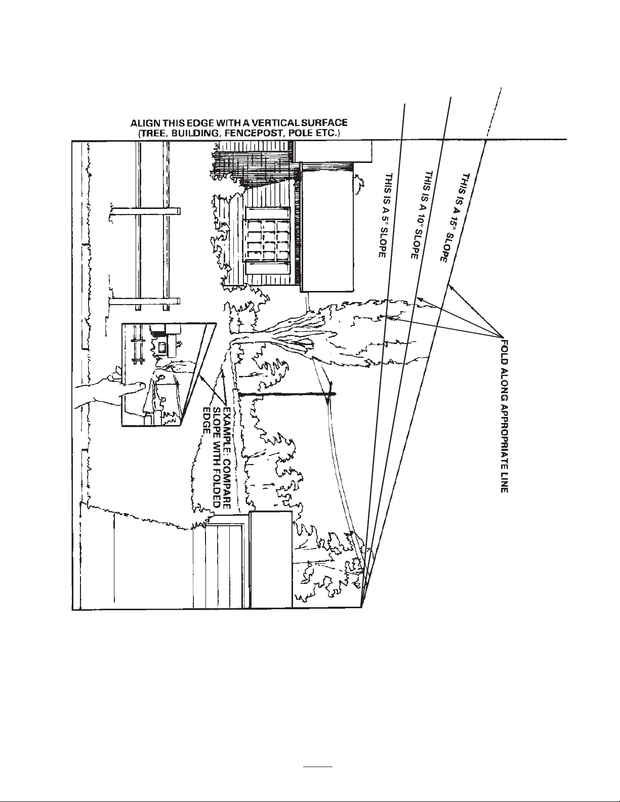
Slope Chart
7

8

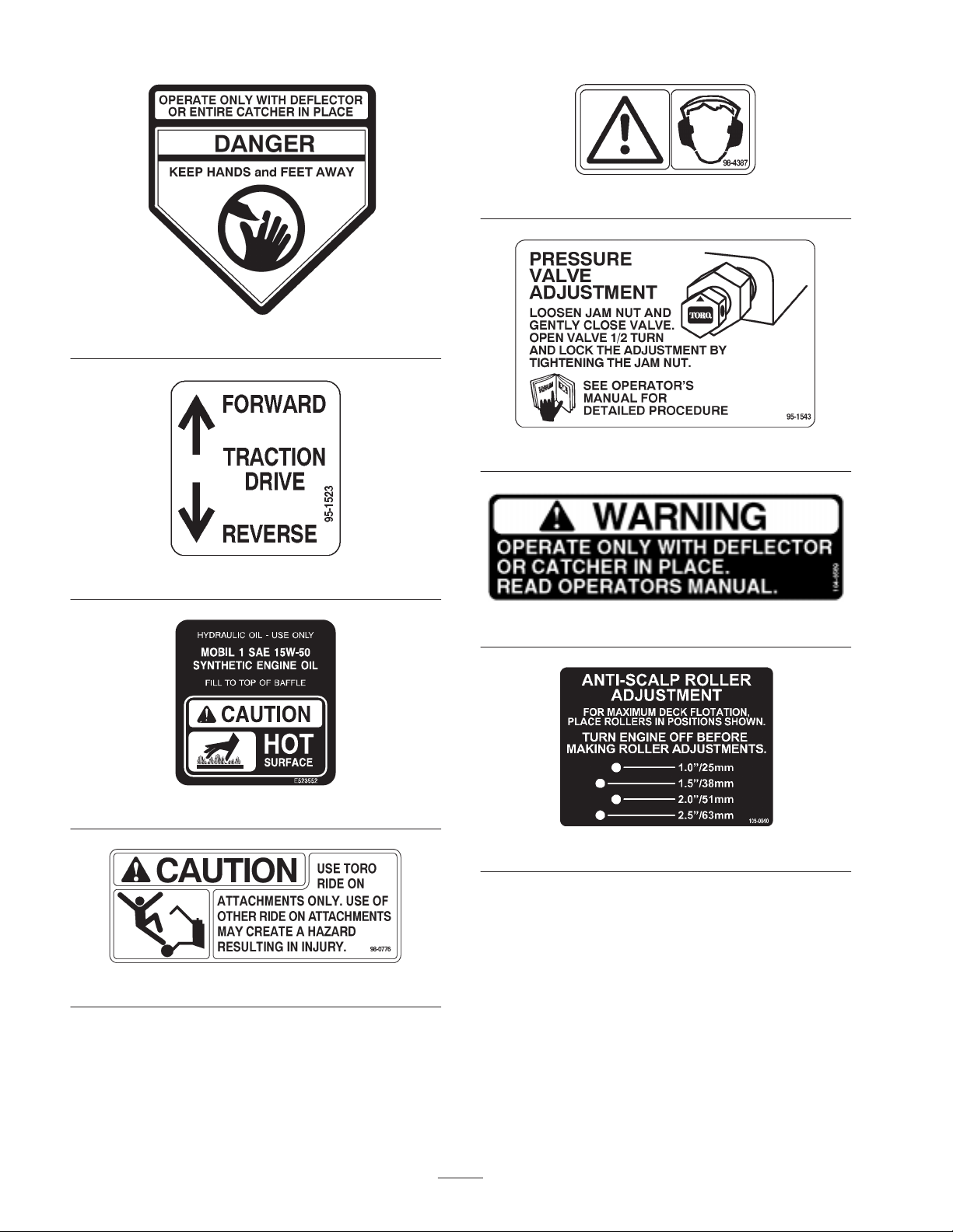
Safety and Instruction Decals
Safety decals and instructions are easily visible to the operator and are located near any
area of potential danger. Replace any decal that is damaged or lost.
82–4590
67–5360
43–8480
66–1340
95–2814
63–8440
68–8340
9
54–9220
95–1523
98–4387
95–1543
104–8569
1–523552
98–0776
105–0840
10
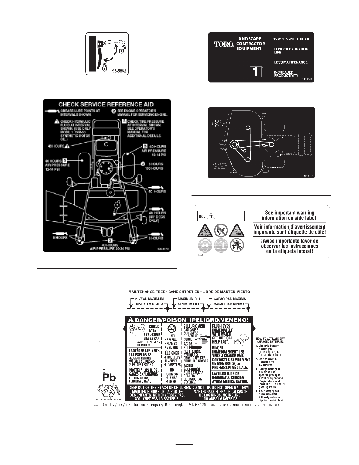
95–5862
104–8172
104–8186
104–8173
104–4163
104–4164
11

104–8171
95–1544
104–8178
12

Gasoline and Oil
Recommended Gasoline
Use UNLEADED Regular Gasoline suitable for
automotive use (85 pump octane minimum). Leaded
regular gasoline may be used if unleaded regular is not
available.
Important Never use methanol, gasoline containing
methanol, or gasohol containing more than 10% ethanol
because the fuel system could be damaged. Do not mix oil
with gasoline.
Danger
In certain conditions, gasoline is extremely
flammable and highly explosive. A fire or
explosion from gasoline can burn you and others
and can damage property.
• Fill the fuel tank outdoors, in an open area,
when the engine is cold. Wipe up any gasoline
that spills.
• Do not fill the fuel tank completely full. Add
gasoline to the fuel tank until the level is 1/4 to
1/2 (6 mm to 13 mm) below the bottom of the
filler neck. This empty space in the tank allows
gasoline to expand.
• Never smoke when handling gasoline, and stay
away from an open flame or where gasoline
fumes may be ignited by a spark.
• Store gasoline in an approved container and
keep it out of the reach of children. Never buy
more than a 30-day supply of gasoline.
• Always place gasoline containers on the ground
away from your vehicle before filling.
• Do not fill gasoline containers inside a vehicle
or on a truck or trailer bed because interior
carpets or plastic truck bed liners may insulate
the container and slow the loss of any static
charge.
• When practical, remove gas–powered
equipment from the truck or trailer and refuel
the equipment with its wheels on the ground.
• If this is not possible, then refuel such
equipment on a truck or trailer from a portable
container, rather than from a gasoline
dispenser nozzle.
• If a gasoline dispenser nozzle must be used,
keep the nozzle in contact with the rim of the
fuel tank or container opening at all times until
fueling is complete.
Warning
Gasoline is harmful or fatal if swallowed.
Long–term exposure to vapors can cause serious
injury and illness.
• Avoid prolonged breathing of vapors.
• Keep face away from nozzle and gas tank or
conditioner opening.
• Keep gas away from eyes and skin.
Using Stabilizer/Conditioner
Use a fuel stabilizer/conditioner in the machine to provide
the following benefits:
• Keeps gasoline fresh during storage of 90 days or less.
For longer storage it is recommended that the fuel tank
be drained.
• Cleans the engine while it runs
• Eliminates gum-like varnish buildup in the fuel
system, which causes hard starting
Important Do not use fuel additives containing
methanol or ethanol.
Add the correct amount of gas stabilizer/conditioner to the
gas.
Note: A fuel stabilizer/conditioner is most effective when
mixed with fresh gasoline. To minimize the chance of
varnish deposits in the fuel system, use fuel stabilizer at
all times.
Filling the Fuel Tank
1. Shut the engine off and chock or block tires.
2. Clean around the fuel tank cap and remove the cap.
Add unleaded regular gasoline to fuel tank, until the
level is 1/4 to 1/2 inch (6 mm to 13 mm) below the
bottom of the filler neck. This space in the tank allows
gasoline to expand. Do not fill the fuel tank
completely full.
3. Install fuel tank cap securely. Wipe up any gasoline
that may have spilled.
Check Engine Oil Level
Before you start the engine and use the machine, check
the oil level in the engine crankcase; refer to Checking Oil
Level, page 27.
13

Assembly
Loose Parts
Note: Use the chart below to verify all parts have been shipped.
DESCRIPTION QTY. USE
Fuel tank
Bolt 5/16 x 7/8 in. (22 mm)
Lock washer 5/16 in.
Washer 5/16 in.
Stud
Spring
Hose clamp
Upper handle
Flanged bolt 3/8 x 1 in. (26 mm)
Flange nut 3/8 in.
Clevis pin
Washer
Hairpin cotter
Battery 1 Activate battery
Operator’s Manual
Engine Operator’s Manual
Parts Catalog
1
2
2
4
2
2
1
1
4
4
2
2
2
1
1
1
Installing fuel tank and fuel line
Installing upper handle to frame
Installing control rods
Read before operating machine
Registration card
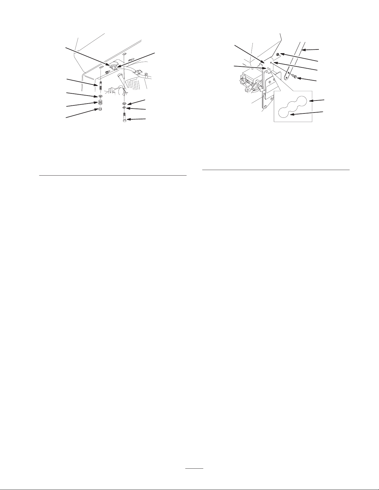
Installing Fuel Tank and Fuel
Line
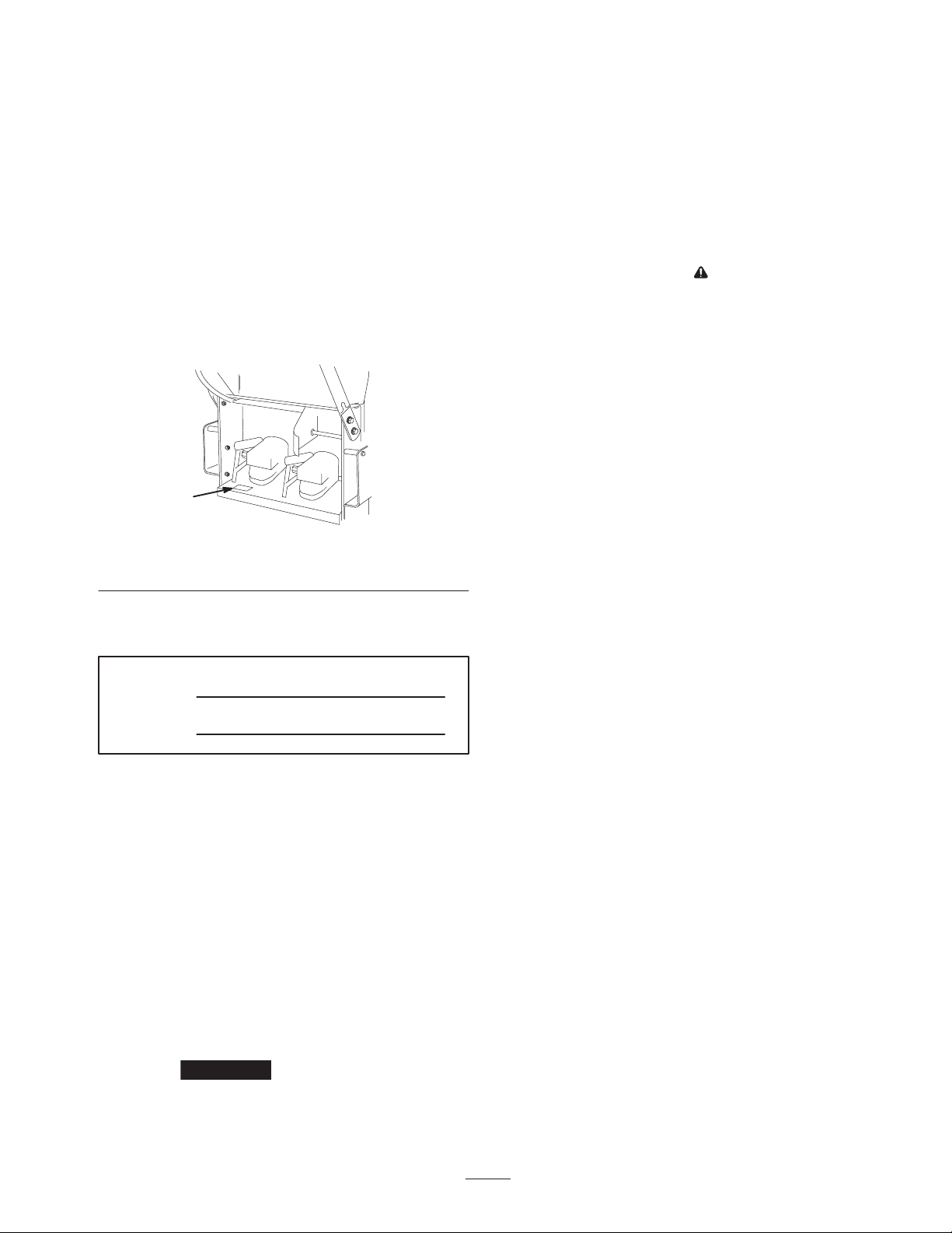
1. Align fuel tank to top of rear frame and secure fuel
tank right side with 2 bolts (5/16 x 7/8 in.), 2 lock
washers (5/16 in.) and 2 washers (5/16) (Fig. 2).
2. Secure fuel tank left side to frame with 2 studs (5/16 x
7/8 in.), 2 washers (5/16 in.), 2 springs and 2 locknuts
(5/16 in.) (Fig. 2).
Note: Tighten left side until it is completely tight and then
unscrew locknut one full turn. This will allow the spring
to work.
1
14
Fill out and return to Toro
8
7
2
1
6
4
5
4
3
3
3
5
6
5
6
m–5339
Figure 2
1. Bolt, 5/8 x 7/8 in.
(22.5 mm)
2. Lock washer, 5/16 in.
3. Washer, 5/16 in.
4. Stud
5. Spring
6. Locknut
7. Hose clamp
8. Fuel tank connection
3. Slide the hose clamp onto the fuel line (Fig. 2).
4. Push the fuel line onto the fuel tank connection and
secure it with a hose clamp (Fig. 2).
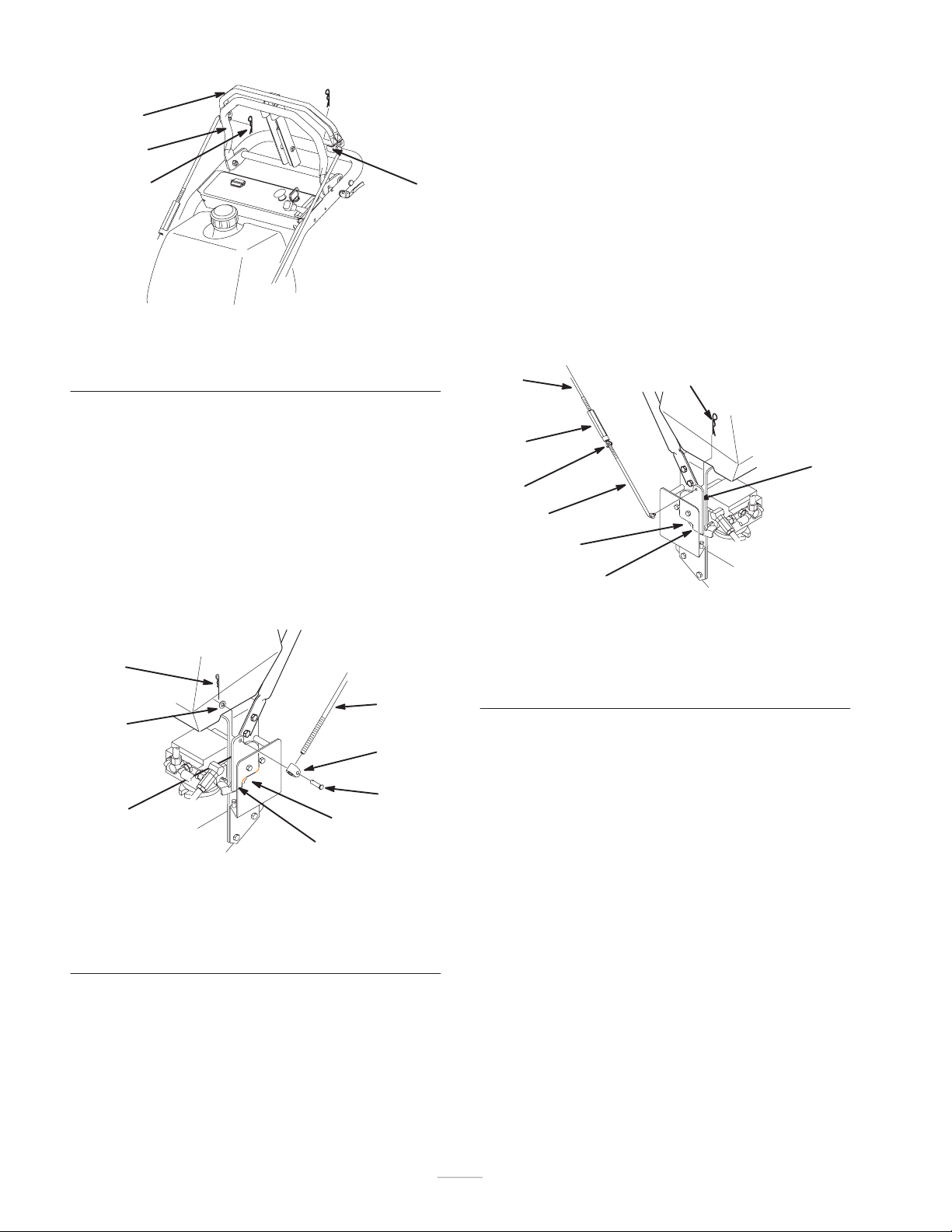
Installing Upper Handle
1. Align upper handle with upper mounting holes in rear
frame (Fig. 3).
2. Secure each upper mounting hole with a flange bolt
(3/8 x 1 in. (26mm)) and flange nut (Fig. 3). Torque
bolts to 25 ft. lbs. (34 N.m).
3. Select high, medium or low position for the lower
mounting hole (Fig. 3). This allows the upper handle
to be adjusted to the user’s height preference.
4. Secure each lower mounting hole with a flange bolt
(3/8 x 1 in. (26mm)) and flange nut (Fig. 3). Torque
bolts to 25 ft. lbs. (34 N.m).
7
8
m–5336
Figure 3
1. Upper handle
2. Rear frame
3. Flange bolt, 3/8 x 1 in.
4. Flange nut, 3/8 in.
5. Upper mounting hole
6. Lower mounting hole
7. Low position
8. High position
Installing Control Rods
Before installing and adjusting control rods loosen quick
release levers and move reference control bar all the way
forward.
Left Control Rod
1. Slide clevis pin through rod fitting and mounting hole
in control bracket (from outside). Secure with washer
and hairpin cotter (Fig. 5).
2. Remove hairpin cotter and rod from upper control bars
(Fig. 4).
3. Press and hold upper control bars against reference
bar, so stop hits (Fig. 4).
15
1
3
2
4
m–5264
Figure 4
1. Upper control bars
2. Hairpin cotter
3. Reference bar
4. Stop
4. Push rod full forward until bearing is against control
bracket stop. Thread rod in or out of fitting on control
bracket until rod aligns with holes in upper control
bars (Fig. 5).
5. When rod and holes in upper control bars line up, turn
rod one additional turn, so rod is shorter.
Note: Upper control bar stop must hit reference bar before
roller bearing hits control bracket stop.
6. Connect rod to upper control bars with previously
removed hairpin cotter (Fig. 4).
6
1
5
3
3. Press and hold upper control bars against reference
bar, so stop hits.
4. Push rod full forward until bearing is against control
bracket stop. Loosen wing nut and thread turnbuckle in
or out until rod aligns with holes in upper control bars
(Fig. 6).
5. When rod and holes in upper control bars line up,
rotate turnbuckle one additional turn, so rod is shorter.
Note: Upper control bar stop must hit reference bar before
roller bearing hits control bracket stop.
6. Connect rod to upper control bars with previously
removed hairpin cotter, tighten wing nut and
turnbuckle (Fig. 4).
1
3
5
2
4
1
7
6
m–5262
Figure 6
1. Control rod–right
2. Control bracket
3. Hairpin cotter
4. Wing nut
5. Turnbuckle
6. Control bracket stop
7. Roller bearing
Adjusting Tracking
4
2
6
7
m–5263
Figure 5
1. Control rod–left
2. Control bracket
3. Rod fitting
4. Clevis pin
5. washer
6. Hairpin cotter
7. Control bracket stop
8. Roller bearing
Right Control Rod
1. Slide rod into control bracket and secure with hairpin
cotter (Fig. 6).
2. Remove hairpin cotter and rod from upper control
bars.
1. After completing assembly check machine tracking.
Operate machine by holding upper control bar against
reference bar with wheel drive engaged.
2. If machine does not track straight, moves more right or
left, adjustment is required.
3. Loosen wing nut on right control rod and rotate
turnbuckle in or out to change tracking. Secure
turnbuckle in position with wing nut (Fig. 6).
4. Check for proper tracking.
Note: Control rods must be adjusted if handle height
position is changed.
Activating the Battery
Bulk electrolyte with 1.265 specific gravity must be
purchased from a local battery supply outlet.
16
 Loading...