

Toro 30297 Parts Catalogue

Form No. 3325-212
Mid–Size Mower
ProLine Hydro with 52” Side Discharge Mower
Model No. 30297—210000001 and Up
Parts Catalog
Ordering Replacement Parts
To order replacement parts, please supply: the part
number, the quantity, and the description of each
part desired.
Understanding Reference Numbers
Each identified part in an illustration has a reference
number. The reference number for a part also appears in
the parts list, along with other information about the part.
This catalog uses two special reference number formats,
one to indicate parts in a service assembly and another
to indicate the quantity of a given part in an illustration.
Service Assembly Reference Numbers
Parts in service assemblies have reference numbers in
the form a:b.
the entire service assembly and the b represents a
sequential number unique to each part within the service
assembly.
The a represents the reference number of
The TORO Company — 2000
All Rights Reserved
For example, a wheel assembly might be identified by
reference number 6, the tire by 6:1, the valve by 6:2,
and the wheel by 6:3. When you order the assembly
identified by reference number 6, you receive all parts
identified by reference numbers 6:1, 6:2, and 6:3.
However, you may also order any part individually.
Reference numbers of this type appear in illustrations
and in part lists.
Reference Numbers Indicating Quantity
In an illustration, if a reference number indicates more
than one part, the reference number has the form nX y.
The n represents the quantity of the part, the X is the
multiplication symbol, and the y represents the reference
number.
For example, in an illustration, the reference number
2X 37 means that two of the parts identified by reference
number 37 are indicated.

3325–212
Contents
Description Page Description Page
Engine and Clutch Assembly 3. . . . . . . . . . . . . . . .
Clutch Assembly No. 54–3200 4. . . . . . . . . . . . . .
Fuel Tank, Hydraulic Tanks, Pump and Filter
Assembly 5. . . . . . . . . . . . . . . . . . . . . . . . . . . . . .
Wheel Motors, Pump Belt and Pump Idler
Assembly 6. . . . . . . . . . . . . . . . . . . . . . . . . . . . . .
Lower Controls Assembly 7. . . . . . . . . . . . . . . . . .
Hydraulic Hose Assembly 8. . . . . . . . . . . . . . . . . .
Upper Handles Assembly 9. . . . . . . . . . . . . . . . . . .
Control Panal Assembly 10. . . . . . . . . . . . . . . . . . . .
Battery Assembly 11. . . . . . . . . . . . . . . . . . . . . . . . .
Deck Assembly 12. . . . . . . . . . . . . . . . . . . . . . . . . . .
Spindles, Idler Pulleys, and Belts Assembly 13. . .
Carrier Frame Assembly 16. . . . . . . . . . . . . . . . . . .
Cylinder/Crankcase 17. . . . . . . . . . . . . . . . . . . . . . . .
Piston/Crankshaft 19. . . . . . . . . . . . . . . . . . . . . . . . .
Valve/Camshaft 21. . . . . . . . . . . . . . . . . . . . . . . . . . .
Lubrication Equipment 23. . . . . . . . . . . . . . . . . . . . .
Cooling Equipment 25. . . . . . . . . . . . . . . . . . . . . . . .
Electric Equipment 27. . . . . . . . . . . . . . . . . . . . . . . .
Control Equipment 29. . . . . . . . . . . . . . . . . . . . . . . . .
Carburetor 31. . . . . . . . . . . . . . . . . . . . . . . . . . . . . . . .
Air Filter/Muffler 33. . . . . . . . . . . . . . . . . . . . . . . . . . .
Fuel Tank/Fuel Valve 35. . . . . . . . . . . . . . . . . . . . . . .
Starter 37. . . . . . . . . . . . . . . . . . . . . . . . . . . . . . . . . . .
Label 39. . . . . . . . . . . . . . . . . . . . . . . . . . . . . . . . . . . .
Electrical Schematic 40. . . . . . . . . . . . . . . . . . . . . . .
Part Description Abbreviations
Part descriptions in this catalog may include the following abbreviations.
Abbreviation Meaning Abbreviation Meaning
AR as required. . . . . . . . . . . . . . . . .
ASM assembly. . . . . . . . . . . . . . . .
CARR carriage. . . . . . . . . . . . . .
DEG degrees. . . . . . . . . . . . . . . .
FH flat head. . . . . . . . . . . . . . . . .
GA gauge. . . . . . . . . . . . . . . . .
HF hex flange. . . . . . . . . . . . . . . . .
HH hex head. . . . . . . . . . . . . . . . .
HHF hex head flange. . . . . . . . . . . . . . . .
HLH hex lag head. . . . . . . . . . . . . . . .
HJ hex jam. . . . . . . . . . . . . . . . . .
HOC height-of-cut. . . . . . . . . . . . . . . .
HS hex socket. . . . . . . . . . . . . . . . .
HSBH hex socket button head. . . . . . . . . . . . . .
HSFH hex socket flat head. . . . . . . . . . . . . . .
HSH hex socket head. . . . . . . . . . . . . . . .
HWH hex washer head. . . . . . . . . . . . . . .
HWHTF hex washer head. . . . . . . . . . . . .
thread forming
HYD hydraulic. . . . . . . . . . . . . . . .
INC incorporated. . . . . . . . . . . . . . . . .
LH left hand. . . . . . . . . . . . . . . . .
NI nylon insert. . . . . . . . . . . . . . . . . .
PPH Phillips pan head. . . . . . . . . . . . . . . .
PTH Phillips truss head. . . . . . . . . . . . . . . .
PTO power take off. . . . . . . . . . . . . . . .
RH right hand. . . . . . . . . . . . . . . . .
SFH slotted fillister head. . . . . . . . . . . . . . . .
SHH slotted hex head. . . . . . . . . . . . . . . .
SQH square head. . . . . . . . . . . . . . . .
SHWH slotted hex washer head. . . . . . . . . . . . . .
SPH slotted pan head. . . . . . . . . . . . . . . .
SRH slotted round head. . . . . . . . . . . . . . . .
STD standard. . . . . . . . . . . . . . . .
TAP self tapping. . . . . . . . . . . . . . . .
TTH Torx truss head. . . . . . . . . . . . . . . .
WH wing head. . . . . . . . . . . . . . . . .
2
33
1
3
4
6
7
3325–212
32
31
30
29
28
34
36
35
34
25
18
23
18
10
12
13
15
12
17
11
12
13
14
15
12
16
24
22
21
20
19
27
26
17
18
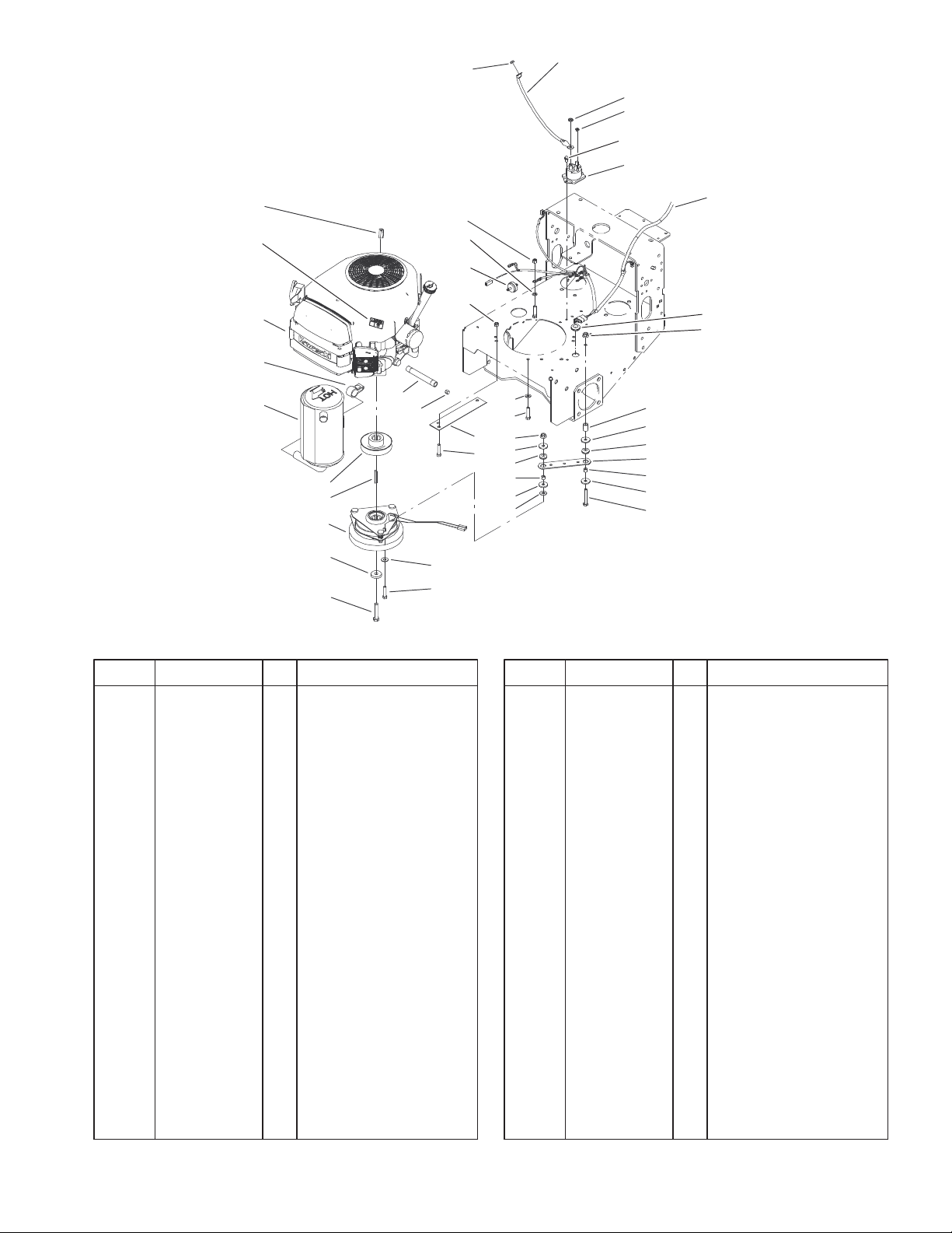
Engine and Clutch Assembly
8
9
10
Sheet No.:3
DescriptionPart No. Qty.Ref. No. DescriptionPart No. Qty.Ref. No.
1 105–0834 1 Cable–Battery, Red
3 32149–1 2 Nut
4 32149–8 2 Nut–Keps
6 32144–4 2 Screw–HWH
7 28–4210 1 Solenoid
8 104–8138 1 Wire Harness
9 237–124 1 Grommet
10 32128–20 2 Nut–HF
11 104–6373 1 Tube – Retainer
12 1–613235 4 Washer
13 1–633630 2 Grommet–Brake
14 1–633543 1 Strap–Clutch/Brake
15 1–633545 2 Spacer–Grommet
16 322–11 1 Screw–HH
17 3256–3 2 Washer–Flat
18 322–7 5 Screw–HH
19 3212–9 1 Screw–HH
20 112843 1 Washer
21 54–3200 1 Clutch/Brake
22 608006 1 Key
23 3256–23 2 Washer–Flat
24 44–5940 1 Pulley
25 94–5847–01 1 Cover – Pulley
26 288–10 1 Cap–Pipe
27 289–19 1 Nipple
30 1 Engine–Kawasaki,
Fh500v–As30
31 63–8440 1 Decal–Surface, Hot
32 2412–87 1 Clamp–Cable
33 32149–2 1 Nut
34 3296–29 4 Nut–Lock
35 56–6360 1 Filter–Fuel
36 3255–8 1 Washer–Lock/Ext
Not serviced
3
3325–212
10
2
3
4
5
8
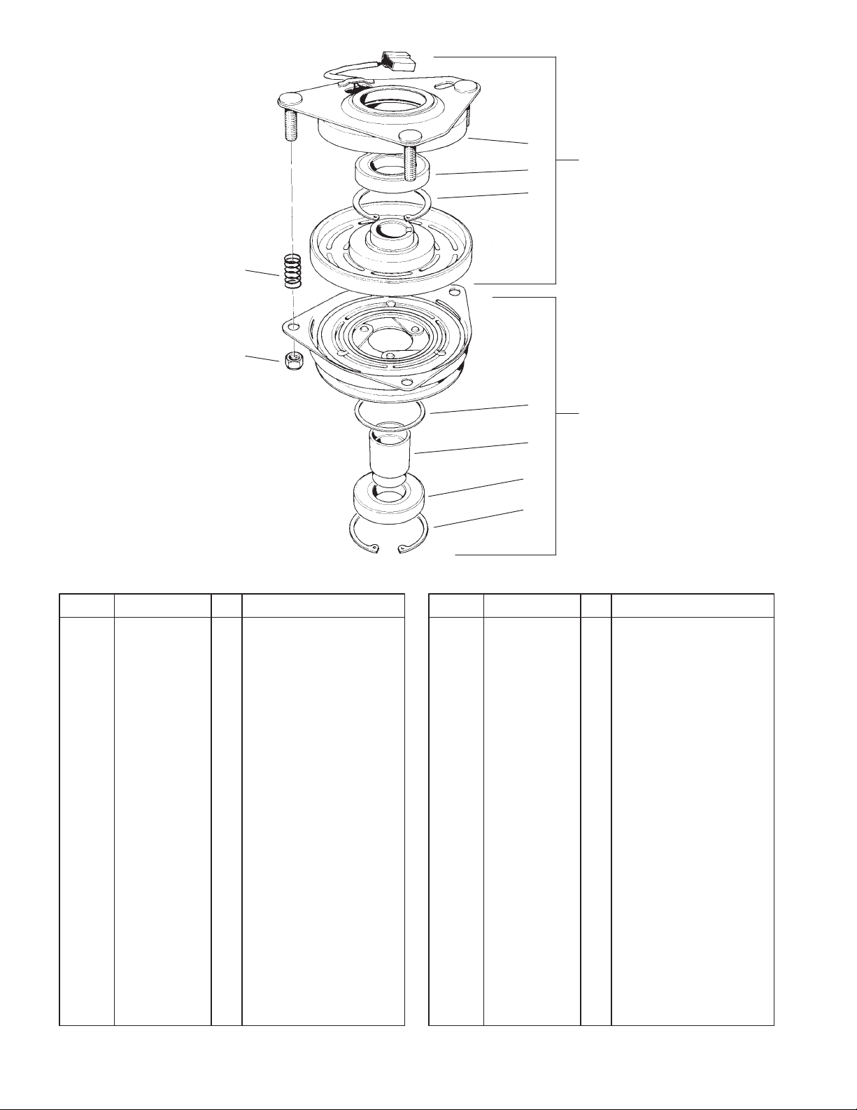
Clutch Assembly No. 54–3200
DescriptionPart No. Qty.Ref. No. DescriptionPart No. Qty.Ref. No.
1 251–291 1 Bearing–Pulley
2 251–292 1 Bearing–Field
3 44–8310 2 Ring–Retaining
4 44–8320 3 Spring
5 3296–6 3 Nut–Lock, NI
6 44–8330 1 Spacer–Bearing,
Pulley
7 44–8340 1 Collar–Bearing
8 44–8360 1 Field Coil–Rotor /
Bearing ASM
9 44–8370 1 Armature / Pulley /
Bearing ASM
10 54–0230 1 Field Bearing ASM
6
9
7
1
3
Sheet No.:A1
T–3726
4

3325–212
1
2
5
25:1
24
25
25:2
23
22
26
27
21:1
24
21:1
21
21
20
28
13
29
30
32
31
18
7
4
3
9
11
10
12
13
14
15
16
17
19
6
8:2
33
8
Sheet No.:4
Fuel Tank, Hydraulic Tanks, Pump and Filter Assembly
DescriptionPart No. Qty.Ref. No. DescriptionPart No. Qty.Ref. No.
1 55–3570 1 Gas Cap ASM
2 1–323551 1 Tank–Fuel
3 1–603988 1 Fitting–Elbow
4 1–513510 1 Fitting–Straight
5 1–513167 1 Cap
6 1–523103 1 Gasket–Cap, Tank
7 321–4 2 Screw–HH
8 99–4625 1 Hydraulic Tank ASM
8:2 1–523552 1 Decal–Tank, Hydraulic
9 1–513645 1 Bushing–Valve, Fuel
10 32128–33 2 Nut–HF
11 104–8121 2 Stud–Threaded
12 1–543277 1 Elbow–Tank, Fuel
13 3256–23 4 Washer–Flat
14 1–633349 2 Spring–Tank, Fuel
15 3296–47 2 Nut–Lock, NI
16 2412–98 4 Clamp
17 47–2980 1 Hose–Gas
18 1–603770 1 Valve–Fuel
19 324–5 4 Screw–HH
20 47–2982 1 Hose–Gas
21 105–0858 3 Fitting–90
21:1 237–42 1 O–Ring
22 1–633750 1 Filter–HYD
22 1–633752 1 Filter–HYD, Winter
23 104–7836 1 Head – Filter
24 353–384 3 Fitting–Straight
25 340–4 4 Adapter
25:1 237–30 1 O–Ring
25:2 237–79 1 O–Ring
26 104–1167 2 Pump–Hydraulic
27 32128–42 4 Nut–HF
28 322–4 2 Screw–HH
29 3253–4 2 Washer–Lock
30 237–124 1 Grommet
31 3253–3 2 Washer–Lock
32 321–3 2 Screw–HH
33 104–8172 1 Decal–Mobil 1
5
3325–212
34
1
2
3
28
30
27
29
26
24
32
33
23
22
25
13
4
31
6
10
14
5
9
15
12:1
12:2
12
7
16
11
8
36
17
20
36:1
36:2
36:3
19
21
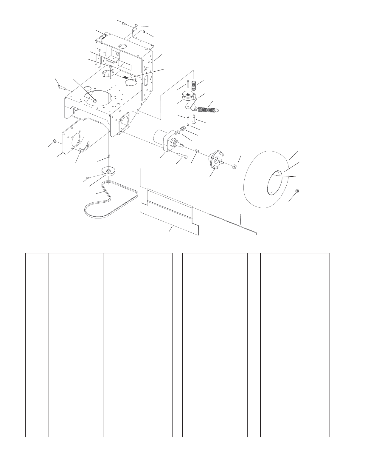
Wheel Motors, Pump Belt and Pump Idler Assembly
DescriptionPart No. Qty.Ref. No. DescriptionPart No. Qty.Ref. No.
1 322–5 2 Screw–HH
2 105–0876–01 1 Bracket–Bushing
3 3296–29 2 Nut–Lock
4 104–1100–01 1 Frame ASM
5 323–9 1 Screw–HH
6 88–1880 1 Spring–Compression
7 86–4770 1 Idler Lever ASM
8 68–2190 1 Spring–Extension
9 62–4540 1 Pulley
10 3296–39 1 Nut–Lock, NI
11 27–6230 1 Bolt–Wheel
12 340–6 4 Fitting–HYD, Straight
12:1 237–30 1 O–Ring
12:2 237–80 1 O–Ring
13 104–1171 2 Motor–Wheel
14 325–11 8 Screw–HH
15 80–6090 2 Key – Pump
16 105–0800 2 Wheel Hub/Stud ASM
17 85–7310 2 Nut–Motor, Wheel
19 242–50 8 Nut–Lug
20 95–1529 1 Rod–Shield
21 95–1526 1 Shield–Trailing
22 82–4110 1 V–Belt
23 95–1528 2 Pulley – Pump
24 3241–5 4 Screw–Set
25 3257–8 2 Key–Woodruff
26 86–4740–01 2 Spacer – Frame
27 104–6326–01 2 Plate–Frame
28 3296–23 8 Nut–Lock, NI
29 32128–23 6 Nut–HF
30 3234–22 2 Screw–HHF
30 3234–32 4 Screw–HHF
31 95–1543 1 Decal–Adjustment,
Valve
32 3296–6 1 Nut–Lock, NI
33 98–0776 1 Decal–Caution
34 95–2814 1 Decal–Shut Off, Fuel
36 104–1198 2 Wheel And Tire ASM
36:1 104–6320 1 Tire
36:2 104–1199 1 Wheel
36:3 232–27 1 Stem–Valve
Sheet No.:5
6
42
41
40
6
7
8
9
11
2
30
14 LH
15 RH
13
5
6
1
2
4
3
5
10
12
3325–212
16
12
3
39
38
37
36
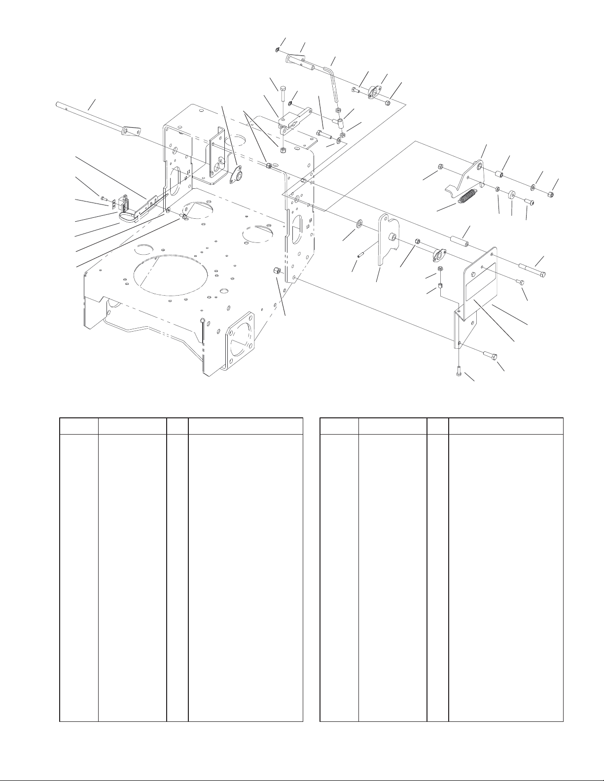
Lower Controls Assembly
DescriptionPart No. Qty.Ref. No. DescriptionPart No. Qty.Ref. No.
1 94–9059 1 Lever–Pivot, RH
2 82–4130 4 Side Flange Bearing
ASM
3 3296–29 6 Nut–Lock
4 82–3790 2 Arm–Pump
5 322–7 4 Screw–HH
6 32151–3 4 Ring–Grip, Ex
7 94–9057 1 Lever–Pivot, LH
8 104–8109 2 Rod–Link
9 321–3 8 Screw–HH
10 94–9062 2 Sleeve
11 3218–2 4 Nut–Jam
12 3256–23 4 Washer–Flat
13 3296–47 2 Nut–Lock, NI
14 82–4330–01 1 Arm–Detent, LH
15 82–4340–01 1 Arm–Detent, RH
16 82–4370 2 Bushing–Arm, Detent
17 82–4240 2 Spacer–Bearing
18 251–259 2 Bearing
19 3274–32 2 Screw–HSBH
20 105–1210 2 Spring – Extension
21 82–3920 2 Stop–Reverse
22 322–14 2 Screw–HH
23 104–8106–01 1 Bracket–Pivot, Left
24 104–8107–01 1 Bracket–Pivot, Right
25 82–4600 2 Decal–Hydro
35
34
33
31 LH
32 RH
30
20
29
28
21
27
17
18
26
26 323–7 6 Screw–HH
27 321–5 2 Screw–HH
28 95–1516 2 Spacer – Tubular
29 32128–10 2 Locknut–Flange
30 3296–42 8 Nut–Lock, NI
31 94–9054–01 1 Arm–Pivot, LH
32 94–9061–01 1 Arm–Pivot, RH
33 32121–4 2 Pin–Roll
34 257–5 2 Washer–Thrust
35 3296–39 6 Nut–Lock, NI
36 32144–4 4 Screw–HWH
37 3256–1 4 Washer–Flat
38 3290–378 2 Tie–Cable
39 65–7410 2 Switch – Single Pole
40 82–4570 2 Switch Plate
41 32144–1 4 Screw–Taptite
42 82–4580–03 2 Bracket – Neutral
19
22
9
23 LH
24 RH
25
Sheet No.:6
7
3325–212
1
2
5
6
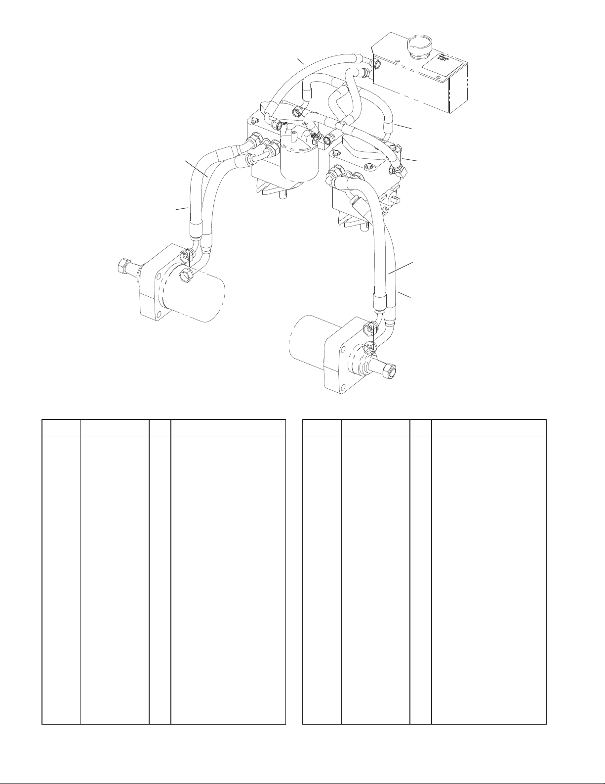
Hydraulic Hose Assembly
DescriptionPart No. Qty.Ref. No. DescriptionPart No. Qty.Ref. No.
1 105–0849 1 Hydraulic Hose ASM
2 105–0847 1 Hydraulic Hose ASM
3 105–0848 1 Hydraulic Hose ASM
4 82–4560 1 Hydraulic Hose ASM
5 82–4550 2 Hydraulic Hose ASM
6 82–4540 1 Hydraulic Hose ASM
3
4
5
Sheet No.:7
8
3
5
3325–212
11
28
29
30
31
34
26
23
24
25
33
1
32
4
2
22
27
6
7
10
7
8
21
20
9
11
12
13
14
15
16
7
19
18
34
17
Sheet No.:8
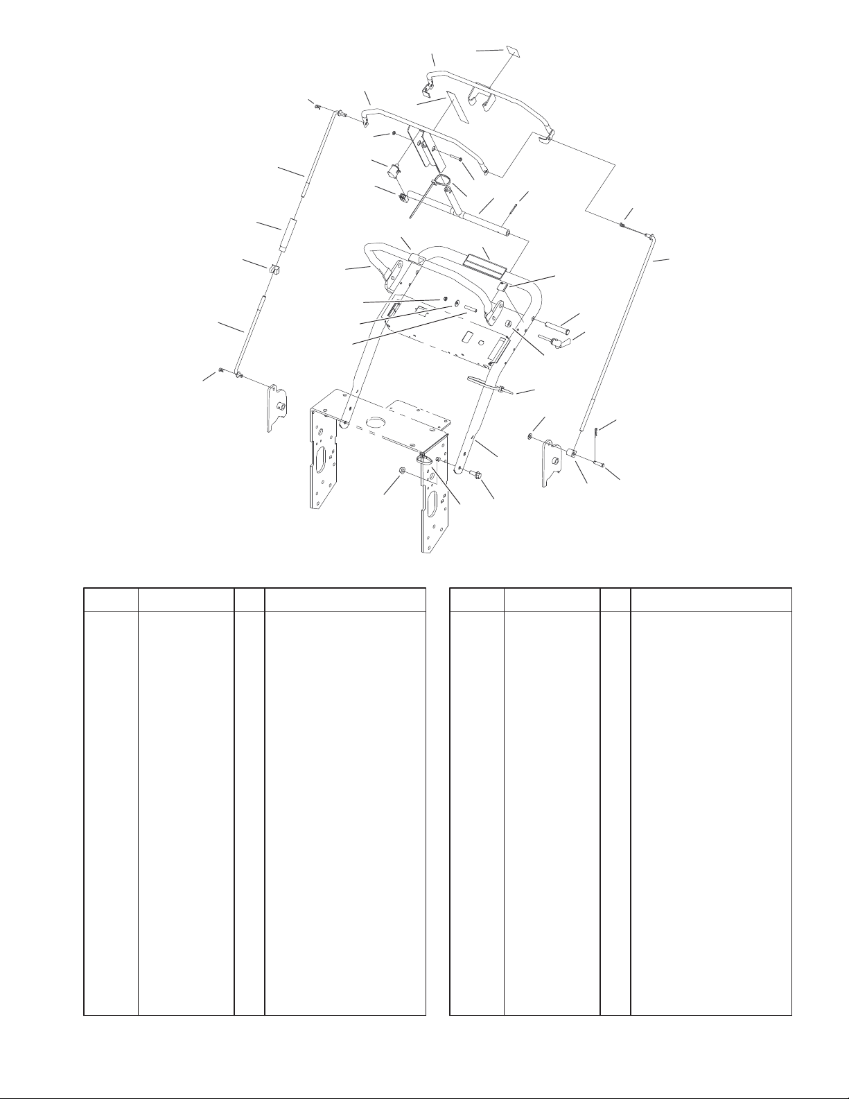
Upper Handles Assembly
DescriptionPart No. Qty.Ref. No. DescriptionPart No. Qty.Ref. No.
1 104–6380–03 1 Control Bar ASM
2 32153–1 1 Nut–Lock
3 104–6386–03 1 Bail ASM
4 95–1524 1 Decal–T Bar
5 95–1523 1 Decal–Drive, Traction
6 32105–1 1 Screw–SHH
7 3290–378 3 Tie–Cable
8 104–6383–03 1 Pivot ASM
9 3272–11 2 Pin–Cotter
10 82–4590 1 Decal – Warning
11 3290–307 2 Pin–Hair
12 94–9095 1 Rod – Control
13 95–5862 1 Decal–Lock, Speed
14 283–55 2 Pin–Clevis
15 95–5853 2 Quick Release Lock
ASM
16 82–3840 2 Spacer
17 283–6 1 Pin–Clevis
18 74–0521 1 Fitting–Rod
19 3256–23 1 Washer–Flat
20 95–5856–03 1 Handle – Upper
21 3234–11 4 Screw–HHF
22 32128–21 4 Nut–HF
23 95–5854 2 Sleeve
24 3290–436 2 Washer–Belleville
25 33023–00 2 Nut–Lock
26 95–1536–03 1 Handle ASM
27 98–4387 1 Decal–Protection, Ear
28 95–1506 1 Rod–Control, Lower
29 32103–3 1 Nut–Wing
30 95–1504 1 Turnbuckle
31 95–1505 1 Rod–Control, Upper
32 218–595 1 Connector–Body
33 82–2190 1 Switch–Bail
34 3272–4 2 Pin–Cotter
9
3325–212
4
3
1
2
21
20
19
18
16
5
17
8
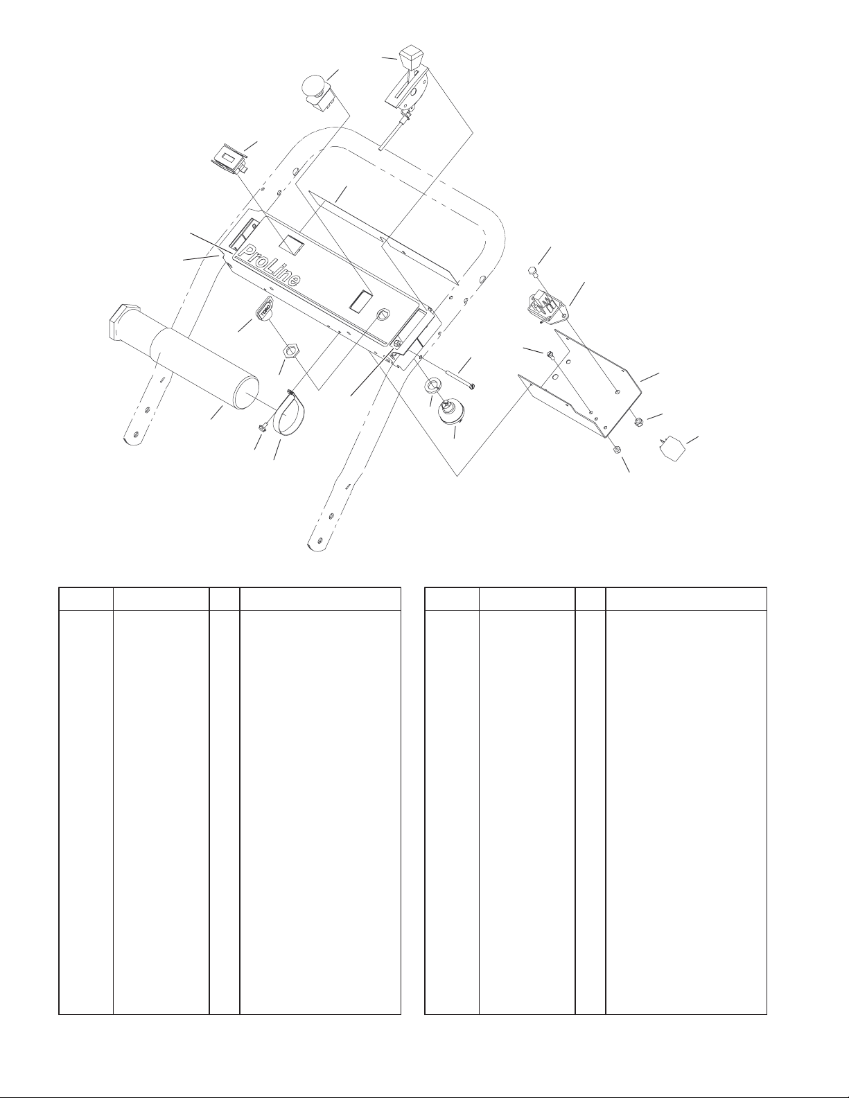
Control Panal Assembly
DescriptionPart No. Qty.Ref. No. DescriptionPart No. Qty.Ref. No.
1 104–8143 1 Hourmeter
2 95–1544 1 Decal – Warning
3 104–8140 1 Switch–PTO
4 100–6450 1 Control– Throttle
5 74–0720 1 Tube–Manual
6 321–3 1 Screw–HH
7 104–8141 1 Module–Delay
8 2412–120 2 R–Clamp
9 93–1187–03 1 Panel–Bottom
10 3296–42 1 Nut–Lock, NI
11 98–7249 1 Relay
13 32105–14 4 Screw
14 116338 1 Key–Switch Ass’y
15 3254–5 1 Washer–Lock, Internal
16 3296–2 4 Nut–Lock
17 32104–76 4 Screw
18 218–461 1 Nut–HH
19 63–8360 2 Key–Ignition
20 104–8177–03 1 Panel–Control
21 104–8178 1 Decal–Control Panel
23 32105–8 1 Screw
24 3296–2 1 Nut–Lock
15
14
13
6
7
23
9
10
11
24
Sheet No.:9
10
10
11
12
3325–212
2
3
4
6
5
10:2
1
10:1
7
9
8
14
13
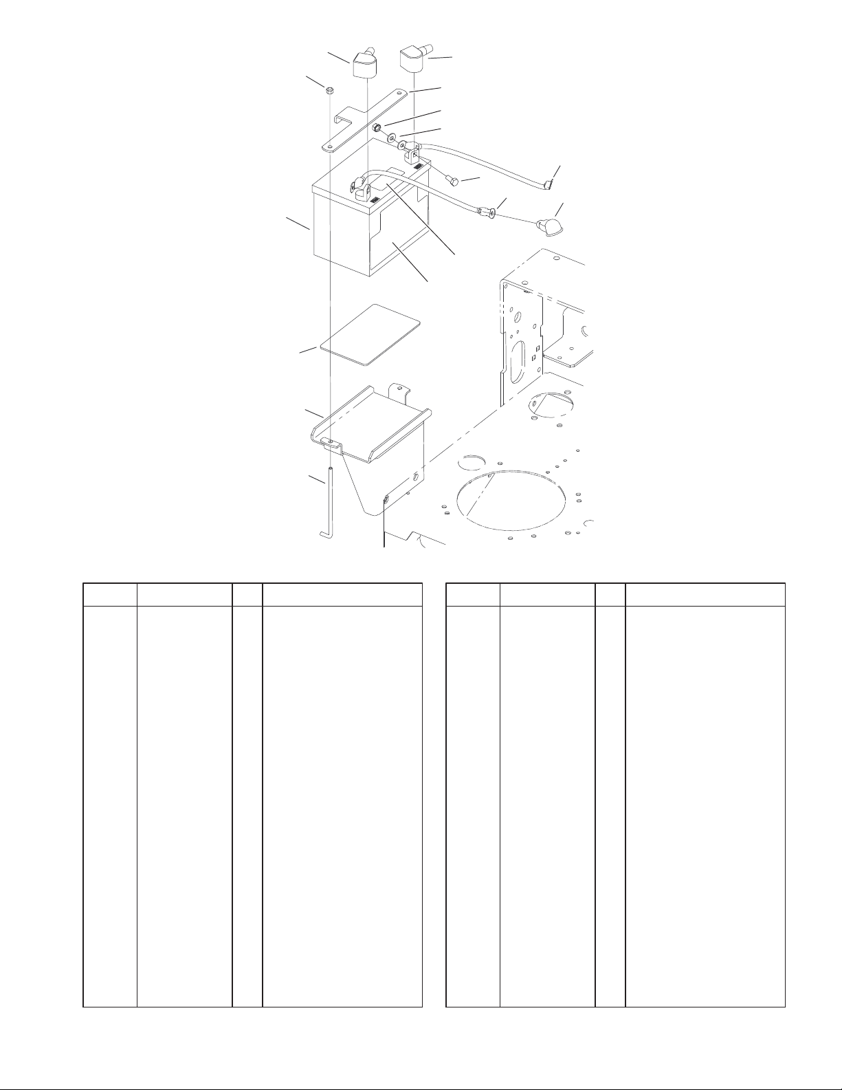
Battery Assembly
DescriptionPart No. Qty.Ref. No. DescriptionPart No. Qty.Ref. No.
1 77–0981 1 Boot–Terminal
2 77–0980 1 Boot–Terminal
3 3296–42 2 Nut–Lock, NI
4 104–8568–03 1 Plate–Battery Hold
Down
5 3256–2 2 Washer–Flat
6 32149–1 2 Nut
7 105–0833 1 Cable–Battery, Black
8 100–6457 1 Cable–Battery,Red
9 322–3 2 Screw–HH
10 104–8162 1 Battery–300 Cca
10:1 104–4163 1 Decal–Battery
10:2 104–4164 1 Decal–Battery
11 62–4300 1 Pad–Anti Skid
12 105–0804–01 1 Battery Plate ASM
13 104–8567 2 Holdown–Battery
14 93–3190 1 Boot–Terminal
Insulator
Sheet No.:10
11
3325–212
4
3
2
1:2
1
5
6
22
23
7
5
8
9
10
10
11
21
15:4
15:3
21
15:2
20
17
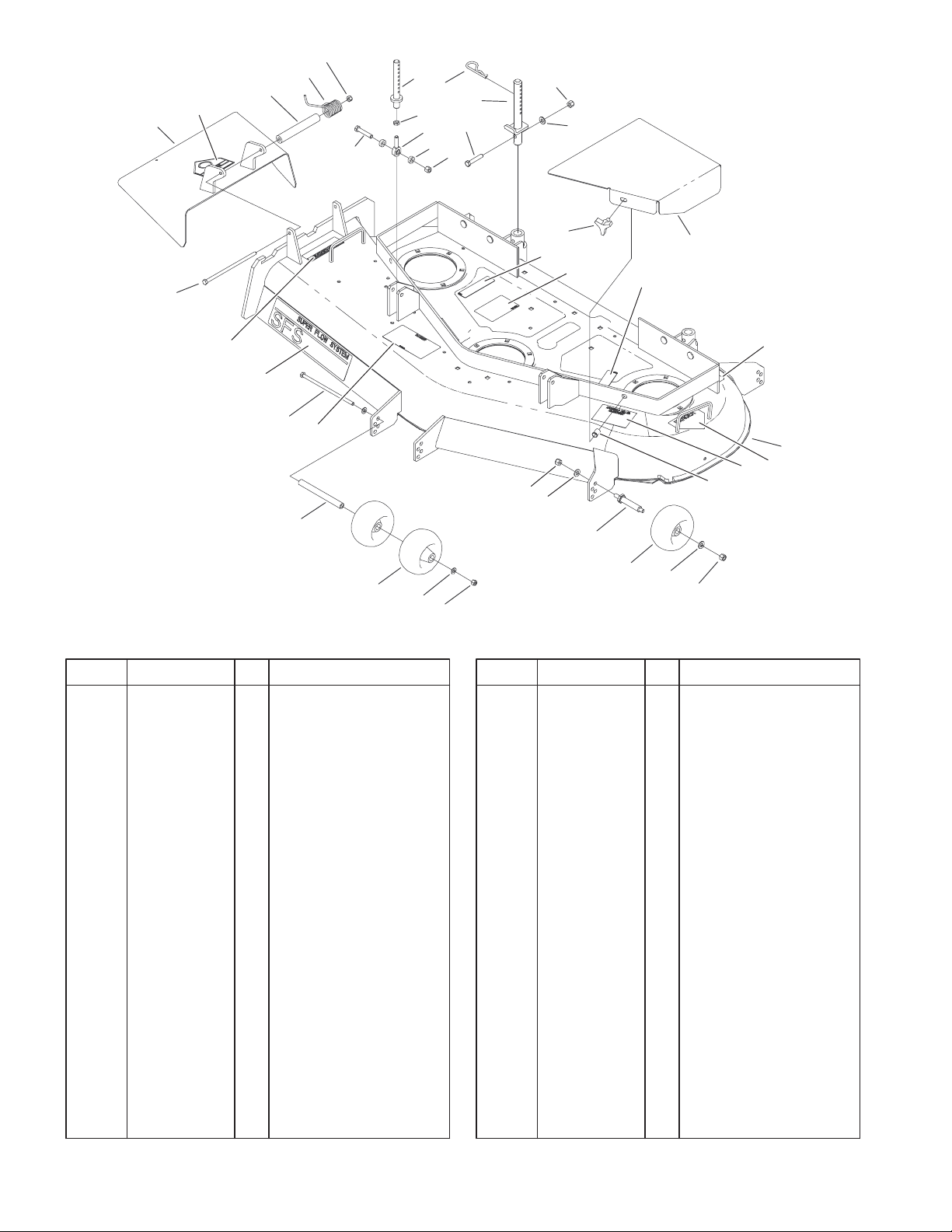
Deck Assembly
DescriptionPart No. Qty.Ref. No. DescriptionPart No. Qty.Ref. No.
1 104–7753 1 Deflector ASM
1:2 54–9220 1 Decal–Danger
2 104–8555 1 Spacer–Mounting,
Deflector
3 104–8554 1 Spring–Torsion
4 3296–29 2 Nut–Lock
5 323–10 4 Screw–HH
6 105–0832 2 Link–Support
7 3220–3 2 Nut–Jam
8 1–613204 2 Balljoint,Stud
9 104–1156 4 Spacer
10 3296–39 10 Nut–Lock, NI
11 3256–24 8 Washer–Flat
12 62–6520 2 Knob
13 104–6389–01 1 Cover–Belt, Right
14 104–6388–01 1 Cover–Belt, Left
15 104–6394 1 Deck ASM
15:2 66–1340 1 Decal–Danger
15:3 98–5953 1 Decal–Sfs
15:4 104–8569 1 Decal–Deflector
Warning
15:5 67–5360 3 Decal–Danger
15:6 104–8186 1 Decal–Belt Routing
15:7 68–8340 1 Decal–Torque
15:8 43–8480 1 Decal–Danger
15:9 105–0840 1 Decal–Anti Scalp
19
12
15:5
15:6
10
11
18
4
15:7
17
11
13 RH
14 LH
10
16
15:7
15:9
15
15:8
Sheet No.: 2
16 32148–10 2 Insert–Threaded
17 68–2730 5 Gage–Wheel
18 99–2842 3 Spacer–Wheel
19 3256–23 2 Washer–Flat
20 98–5967 1 Spacer – Wheel
21 322–50 2 Screw–Cap
22 3290–256 6 Pin–Cotter, Hair
23 105–0831 2 Rod ASM
12
34
33
32
7
6
3
5
2
1
6
4
3
8
9
10
11
13
27
12
6
3
14
23
16
1
17
18
1
19
20
21
26
24
3
25
21:2
6
21:1
22
19
15
3325–212
31
30
29
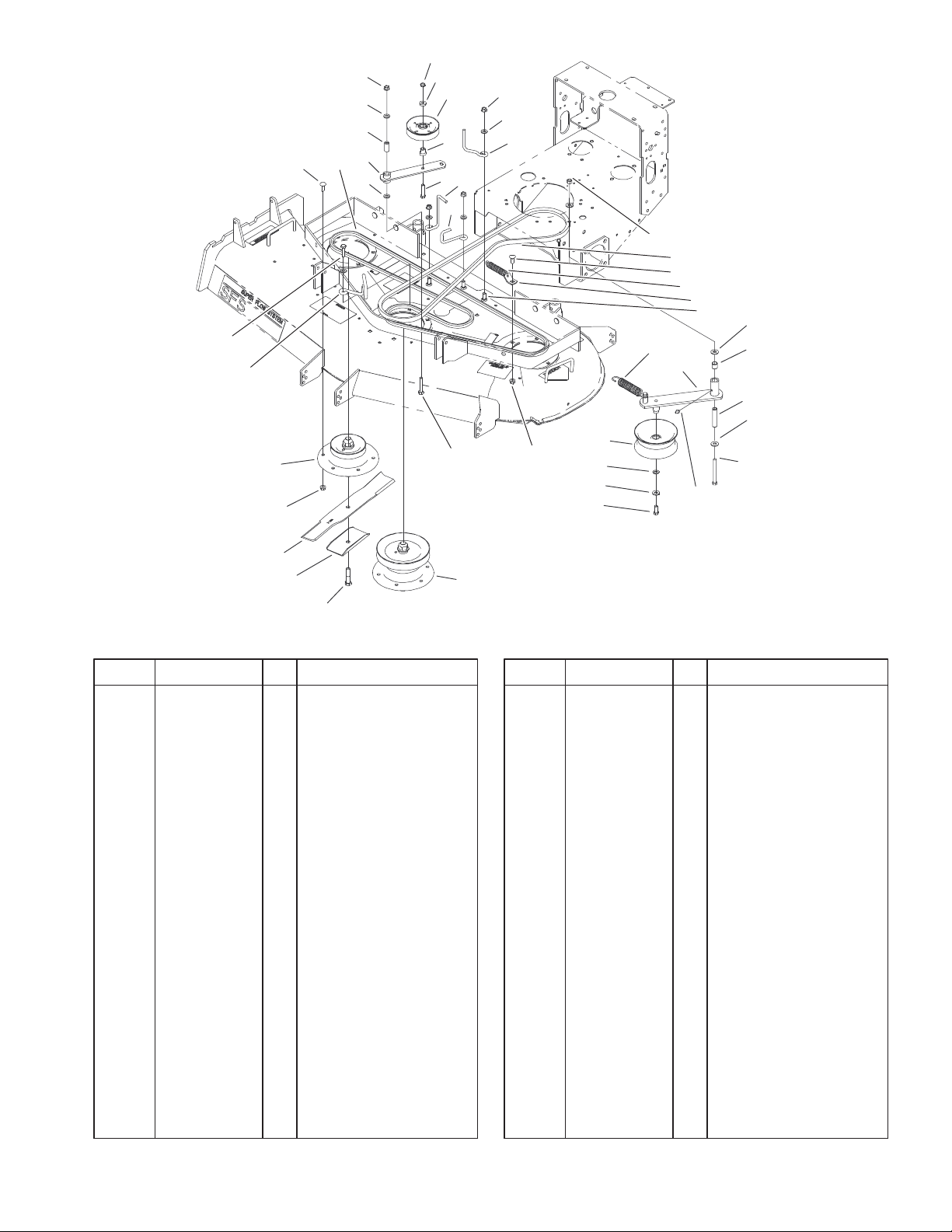
Spindles, Idler Pulleys, and Belts Assembly
DescriptionPart No. Qty.Ref. No. DescriptionPart No. Qty.Ref. No.
1 3231–22 19 Screw–CARR
2 104–6397 1 V–Belt, Deck
3 3256–24 7 Washer–Flat
4 104–6375 1 Idler Arm ASM
5 51–3640 1 Sleeve–Pivot, Idler
6 32128–21 21 Nut–HF
7 3296–5 1 Nut–Lock NI
8 7–0081 1 Washer–Flat
9 65–5940 1 Pulley–Idler
10 104–6379 1 Bushing–Pulley
11 3211–8 1 Screw–HH
12 98–5980 1 Guide – Belt
13 104–6396 1 Guide–Belt
14 52–4780 1 Rod–Belt
15 323–42 1 Screw–HH
16 104–6398 1 V–Belt, PTO
17 51–3650 1 Spring – Extension
18 104–6374 1 Plate – Spring
19 1–809107 2 Washer–Hardened
20 104–8161 1 Spring–Extension
21 104–6370 1 Idler Arm ASM
21:1 1–513034 2 Sleeve–Bearing
21:2 302–5 1 Fitting–Grease
22 104–6377 1 Tube – Idler
23 3296–39 1 Nut–Lock, NI
24 1–413099 1 Pulley–Idler
28
Sheet No.: 3
25 98–5975 1 Washer–Belleville
26 323–6 1 Screw–HH
27 323–11 1 Screw–HH
28 104–6315 1 Spindle Housing ASM
29 44–2200 3 Screw – Blade
30 92–9820 3 Stiffener – Blade
31 27–0990 3 Blade
32 104–6317 2 Spindle Housing ASM
33 105–0850 1 Guide–Belt
34 323–8 1 Screw–HH
13
3325–212
2
1
3
6
4
9
4
5
8
7
Sheet No.: A1
C–3011
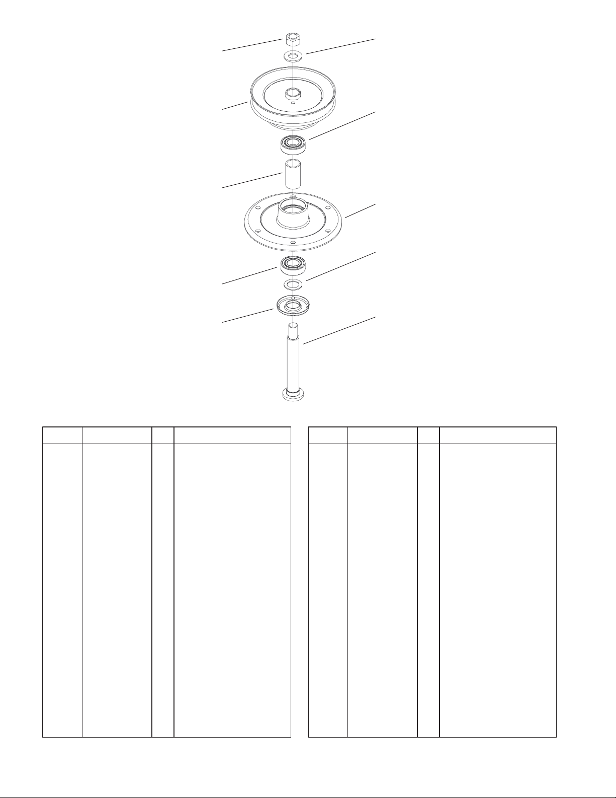
Spindle Housing Assembly No. 104–6315
DescriptionPart No. Qty.Ref. No. DescriptionPart No. Qty.Ref. No.
1 3219–7 1 Nut–Hex
2 7–4150 1 Washer–Pinion
3 104–1117 1 Pulley And Hub ASM
4 104–6325 2 Bearing
5 104–6307 1 Spindle Housing
6 104–6313 1 Spacer–Bearing
7 104–6311 1 Shaft–Spindle
8 88–7540 1 Washer – Backup
9 79–1920 1 Shield–Bearing
14
 Loading...