

Toro 30260 Parts Catalogue

Form No. 3326-859
Mid–Size Mower
ProLine Gear with Side Discharge Mower
Model No. 30260—210010001 and Up
Parts Catalog
Ordering Replacement Parts
To order replacement parts, please supply: the part
number, the quantity, and the description of each
part desired.
Understanding Reference Numbers
Each identified part in an illustration has a reference
number. The reference number for a part also appears in
the parts list, along with other information about the part.
This catalog uses two special reference number formats,
one to indicate parts in a service assembly and another
to indicate the quantity of a given part in an illustration.
Service Assembly Reference Numbers
Parts in service assemblies have reference numbers in
the form a:b.
the entire service assembly and the b represents a
sequential number unique to each part within the service
assembly.
The a represents the reference number of
The TORO Company — 2001
All Rights Reserved
For example, a wheel assembly might be identified by
reference number 6, the tire by 6:1, the valve by 6:2,
and the wheel by 6:3. When you order the assembly
identified by reference number 6, you receive all parts
identified by reference numbers 6:1, 6:2, and 6:3.
However, you may also order any part individually.
Reference numbers of this type appear in illustrations
and in part lists.
Reference Numbers Indicating Quantity
In an illustration, if a reference number indicates more
than one part, the reference number has the form nX y.
The n represents the quantity of the part, the X is the
multiplication symbol, and the y represents the reference
number.
For example, in an illustration, the reference number
2X 37 means that two of the parts identified by reference
number 37 are indicated.

3326–859
Contents
Description Page Description Page
Engine and Clutch Assembly 3. . . . . . . . . . . . . . . .
Clutch Assembly No. 54–3200 4. . . . . . . . . . . . . .
Fuel Tank Assembly 5. . . . . . . . . . . . . . . . . . . . . . .
Lower Control Assembly 6. . . . . . . . . . . . . . . . . . .
Transmission and Drive System Assembly 7. . . .
Wheel Drive and Brake System Assembly 8. . . .
Handle Assembly 9. . . . . . . . . . . . . . . . . . . . . . . . . .
Control Panel Assembly 10. . . . . . . . . . . . . . . . . . . .
Deck Assembly 11. . . . . . . . . . . . . . . . . . . . . . . . . . .
Spindle, Idler Pulley, and Belt Assembly 12. . . . . .
Spindle Housing Assembly No. 104–6315 13. . . .
Spindle Housing Assembly No. 104–6317 14. . . .
Carrier Frame Assembly 15. . . . . . . . . . . . . . . . . . .
Cylinder / Crankcase Assembly 16. . . . . . . . . . . . .
Valve / Camshaft Assembly 18. . . . . . . . . . . . . . . . .
Piston / Crankshaft Assembly 20. . . . . . . . . . . . . . .
Lubrication Equipment Assembly 21. . . . . . . . . . . .
Cooling Equipment Assembly 22. . . . . . . . . . . . . . .
Electrical Equipment Assembly 24. . . . . . . . . . . . . .
Control Equipment Assembly 26. . . . . . . . . . . . . . .
Carburetor Assembly 28. . . . . . . . . . . . . . . . . . . . . .
Air Filter / Muffler Assembly 30. . . . . . . . . . . . . . . . .
Fuel Tank / Fuel Valve Assembly 31. . . . . . . . . . . .
Starter Assembly 32. . . . . . . . . . . . . . . . . . . . . . . . . .
Decals 33. . . . . . . . . . . . . . . . . . . . . . . . . . . . . . . . . . .
Electrical Schematic 34. . . . . . . . . . . . . . . . . . . . . . .
Accessories
Description Model / Part No. Description Model / Part No.
Midsize Sulky 30123. . . . . . . . . . . . . . . . . . . . . . . . . . . . .
ProLine Midsize Platform Sulky 30110. . . . . . . . . . . . .
Hourmeter Kit 105–2695. . . . . . . . . . . . . . . . . . . . . . . . .
36/44/52/62in Soft Bagger F/D 30104. . . . . . . . . . . . . .
36/44/52/62in Steel Bagger F/D 30107. . . . . . . . . . . . .
44/52in Striping Kit 30121. . . . . . . . . . . . . . . . . . . . . . . .
52in Deck Recycler Kit 59225. . . . . . . . . . . . . . . . . . . . .
52in Mulching Kit 59227. . . . . . . . . . . . . . . . . . . . . . . . . .
Atomic Blade ASM 104–1301. . . . . . . . . . . . . . . . . . . .
18in Blade 56–2390. . . . . . . . . . . . . . . . . . . . . . . . . . . . .
18in Recycler Blade 92–7961. . . . . . . . . . . . . . . . . . . .
Part Description Abbreviations
Part descriptions in this catalog may include the following abbreviations.
Abbreviation Meaning Abbreviation Meaning
AR as required. . . . . . . . . . . . . . . . .
ASM assembly. . . . . . . . . . . . . . . .
CARR carriage. . . . . . . . . . . . . .
DEG degrees. . . . . . . . . . . . . . . .
FH flat head. . . . . . . . . . . . . . . . .
GA gauge. . . . . . . . . . . . . . . . .
HF hex flange. . . . . . . . . . . . . . . . .
HH hex head. . . . . . . . . . . . . . . . .
HHF hex head flange. . . . . . . . . . . . . . . .
HLH hex lag head. . . . . . . . . . . . . . . .
HJ hex jam. . . . . . . . . . . . . . . . . .
HOC height-of-cut. . . . . . . . . . . . . . . .
HS hex socket. . . . . . . . . . . . . . . . .
HSBH hex socket button head. . . . . . . . . . . . . .
HSFH hex socket flat head. . . . . . . . . . . . . . .
HSH hex socket head. . . . . . . . . . . . . . . .
HWH hex washer head. . . . . . . . . . . . . . .
HWHTF hex washer head. . . . . . . . . . . . .
thread forming
HYD hydraulic. . . . . . . . . . . . . . . .
INC incorporated. . . . . . . . . . . . . . . . .
LH left hand. . . . . . . . . . . . . . . . .
NI nylon insert. . . . . . . . . . . . . . . . . .
PPH Phillips pan head. . . . . . . . . . . . . . . .
PTH Phillips truss head. . . . . . . . . . . . . . . .
PTO power take off. . . . . . . . . . . . . . . .
RH right hand. . . . . . . . . . . . . . . . .
SFH slotted fillister head. . . . . . . . . . . . . . . .
SHH slotted hex head. . . . . . . . . . . . . . . .
SQH square head. . . . . . . . . . . . . . . .
SHWH slotted hex washer head. . . . . . . . . . . . . .
SPH slotted pan head. . . . . . . . . . . . . . . .
SRH slotted round head. . . . . . . . . . . . . . . .
STD standard. . . . . . . . . . . . . . . .
TAP self tapping. . . . . . . . . . . . . . . .
TTH Torx truss head. . . . . . . . . . . . . . . .
WH wing head. . . . . . . . . . . . . . . . .
2
1
2
3
4
5
3326–859
25
5
27
24
15
16
16
23
22
21
19
18
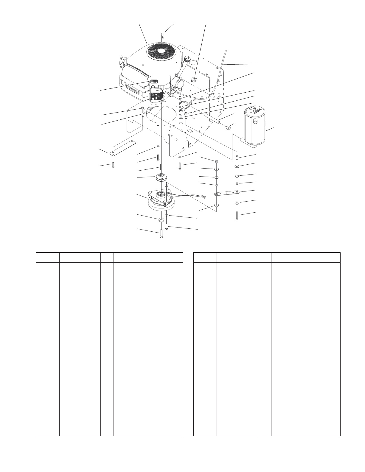
Engine and Clutch Assembly
DescriptionPart No. Qty.Ref. No. DescriptionPart No. Qty.Ref. No.
1 1 Engine–Kawasaki,
Fh500v–As25
2 2412–87 1 Clamp–Cable
3 56–6360 1 Filter–Fuel
4 104–8137 1 Harness–Wire
5 3296–29 4 Nut–Lock, NI
6 3255–8 1 Washer–Lock/Ext
7 32128–20 2 Nut–HF
8 237–124 1 Grommet
9 104–6373 1 Tube–Retainer
10 1–613235 4 Washer
11 1–633630 2 Grommet–Brake
12 1–633545 2 Spacer–Grommet
13 1–633543 1 Strap–Clutch/Brake
14 322–11 1 Screw–HH
15 3256–23 2 Washer–Flat
16 322–7 5 Screw–HH
17 3256–3 2 Washer–Flat
18 3212–9 1 Screw–HH
19 112843 1 Washer
21 54–3200 1 Clutch/Brake
22 105–0827 1 Pulley–Drive
23 608006 1 Key
24 94–5847–01 1 Cover–Pulley
25 63–8440 1 Decal–Surface, Hot
26 100–6467 1 Muffler
6
7
8
28
10
11
12
10
29
15
7
16
17
16
9
10
11
12
13
10
14
26
27 100–6468 1 Clamp–Muffler
28 289–19 1 Nipple
29 288–10 1 Cap–Pipe
Sheet No.: 4
3
3326–859
10
2
3
4
5
8
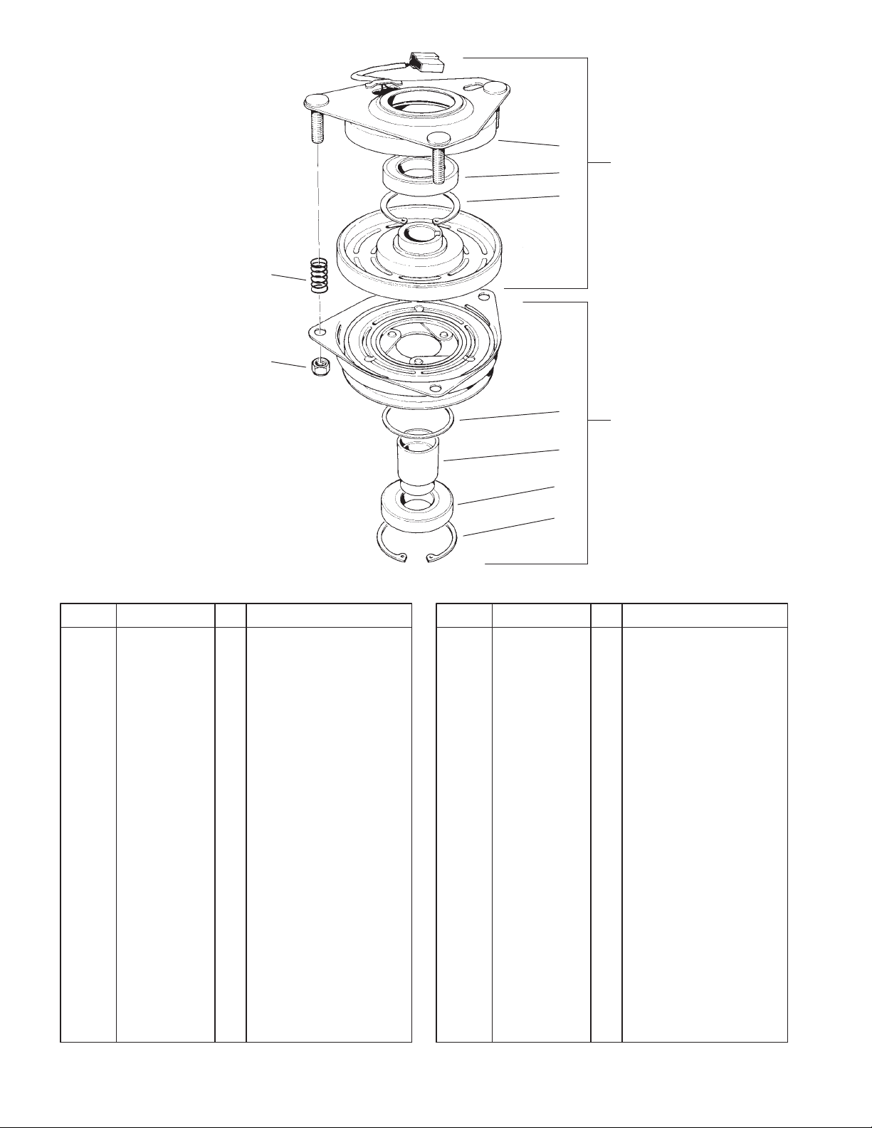
Clutch Assembly No. 54–3200
DescriptionPart No. Qty.Ref. No. DescriptionPart No. Qty.Ref. No.
1 251–291 1 Bearing–Pulley
2 251–292 1 Bearing–Field
3 44–8310 2 Ring–Retaining
4 44–8320 3 Spring
5 3296–6 3 Nut–Lock, NI
6 44–8330 1 Spacer–Bearing,
Pulley
7 44–8340 1 Collar–Bearing
8 44–8360 1 Field Coil, Rotor,
Bearing ASM
9 44–8370 1 Armature Pulley
Bearing ASM
10 54–0230 1 Field Bearing ASM
6
9
7
1
3
Sheet No.: A1
T–3726
4
10
11
10
20
17
19
16
15
14
12
3326–859
1
2
3
18
4
5
6
7
8
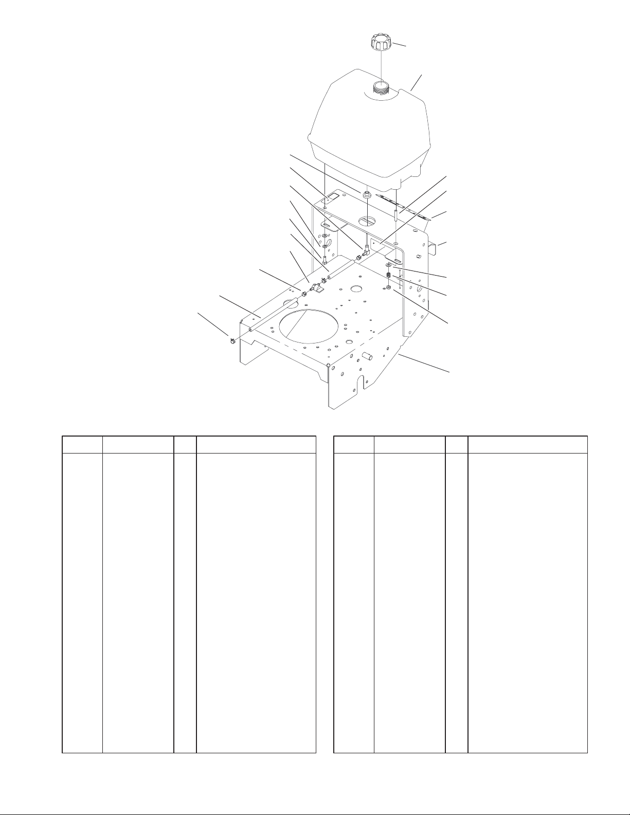
Fuel Tank Assembly
DescriptionPart No. Qty.Ref. No. DescriptionPart No. Qty.Ref. No.
1 55–3570 1 Gas Cap ASM
2 1–323551 1 Tank–Fuel
3 104–8121 2 Stud–Threaded
4 98–3256 1 Decal–Speed, Ground
5 104–8102–01 1 Plate–Gate, Shift
6 3256–23 4 Washer–Flat
7 1–633349 2 Spring–Tank, Fuel
8 3296–47 2 Nut–Lock, NI
9 105–4666–01 1 Traction Frame ASM
10 2412–98 4 Clamp
11 47–2982 1 Hose–Gas
12 1–603770 1 Valve–Fuel
14 47–2980 1 Hose–Gas
15 322–4 2 Screw–HH
16 3253–4 2 Washer–Lock
17 95–2814 1 Decal–Shut Off, Fuel
18 98–0776 1 Decal–Caution
19 1–543277 1 Elbow–Tank, Fuel
20 1–513645 1 Bushing–Valve, Fuel
9
Sheet No.: 5
5
3326–859
32
21
21
19 LH
20 RH
18
17
1
2
3
4
2
5
3
6
7
8 LH
9 RH
10
2
31
Lower Control Assembly
DescriptionPart No. Qty.Ref. No. DescriptionPart No. Qty.Ref. No.
1 32103–25 2 Nut–Wing
2 3256–23 6 Washer–Flat
3 3290–307 4 Pin–Hair
4 52–2890 2 Bushing–Nylon
5 74–0521 2 Fitting–Rod
6 283–6 2 Pin–Clevis
7 74–0040 4 Spacer–Pivot, Idler
8 67–6380–01 1 Bracket–Support, LH
9 67–6370–01 1 Bracket–Support, RH
10 323–16 2 Screw–HH
11 323–6 4 Screw–HH
12 3296–23 2 Nut–Lock, NI
13 95–2800 2 Pulley–Idler
14 95–2801 2 Spacer–Pulley
15 74–0220–01 1 Bracket–Idler, LH
16 74–0230–01 1 Bracket–Idler, RH
17 51–4450 2 Screw–Leveler
18 68–9690 2 Fitting–Rod
19 51–4380 1 Spring–Torsion, LH
20 51–4370 1 Spring–Torsion, RH
21 3296–39 6 Nut–Lock, NI
31 3234–32 6 Screw–HHF
32 32128–23 6 Nut–HF
15 LH
16 RH
14
13
12
Sheet No.: 6
11
6
3326–859
1
29
28
27
26
27:1
25
24
30
31
32
33
23
19
12
20
16
10
2
5
6
9
7
8
11
12
13
14
15
3
4
17
18
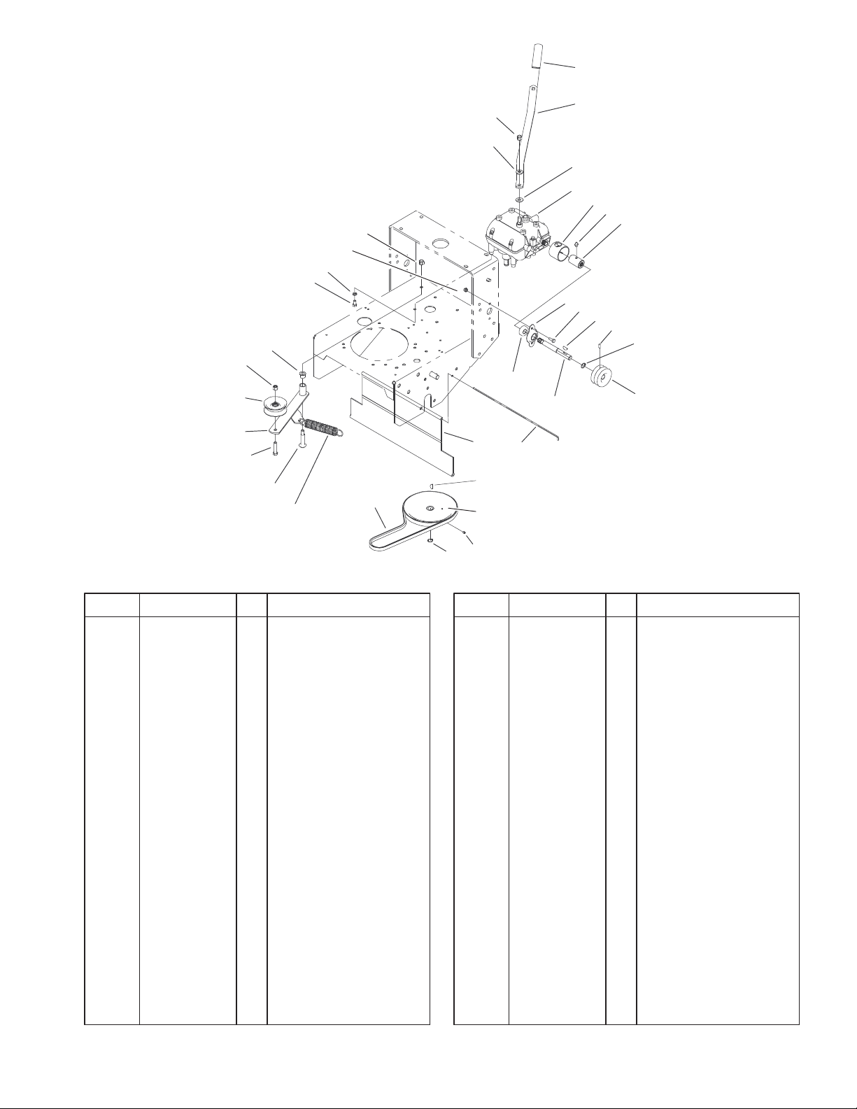
Transmission and Drive System Assembly
DescriptionPart No. Qty.Ref. No. DescriptionPart No. Qty.Ref. No.
1 47–1970 1 Grip
2 98–3274–03 1 Lever–Shift
3 3296–6 1 Nut–Lock, NI
4 98–5975 1 Washer–Belleville
5 1–323379 1 Washer–Lever, Shifter
6 1–323500 1 Transmission
7 302–5 2 Fitting–Grease
8 98–0789 2 Coupler
9 51–4220 2 Guard–Coupler
10 1–323254 2 Flange–Output
11 321–4 4 Screw–HH
12 3257–5 3 Key–Woodruff
13 3245–9 2 Screw–Set
14 32151–62 2 Ring–Retaining
15 105–0828 2 Pulley–Transmission
16 104–1102 2 Shaft–Output
17 1–323252 2 Bearing–Shaft
18 95–1529 1 Rod–Shield
19 95–1526 1 Shield–Trailing
20 51–4190 1 Pulley–Driven
21 3245–1 1 Screw–Set, HSH
22 32120–64 1 Ring–Snap, External
23 26–9671 1 V–Belt
24 68–2190 1 Spring
25 27–6230 1 Bolt–Wheel
26 323–9 1 Screw–HH
21
22
27 16–7509 1 Lever–Idler
27:1 256–155 2 Bushing–Flange
28 62–4540 1 Pulley
29 3296–39 1 Nut–Lock, NI
30 322–2 4 Screw–HH
31 3253–4 4 Washer–Lock
32 3296–42 4 Nut–Lock, NI
33 3296–6 1 Nut–Lock, NI
Sheet No.: 7
7

3326–859
30
31
32
29
28
27
17
25
6
5
3 LH
4 RH
8
9
2
7
26
16
1
10
12
13
11
14
15
16
17
34
34:1
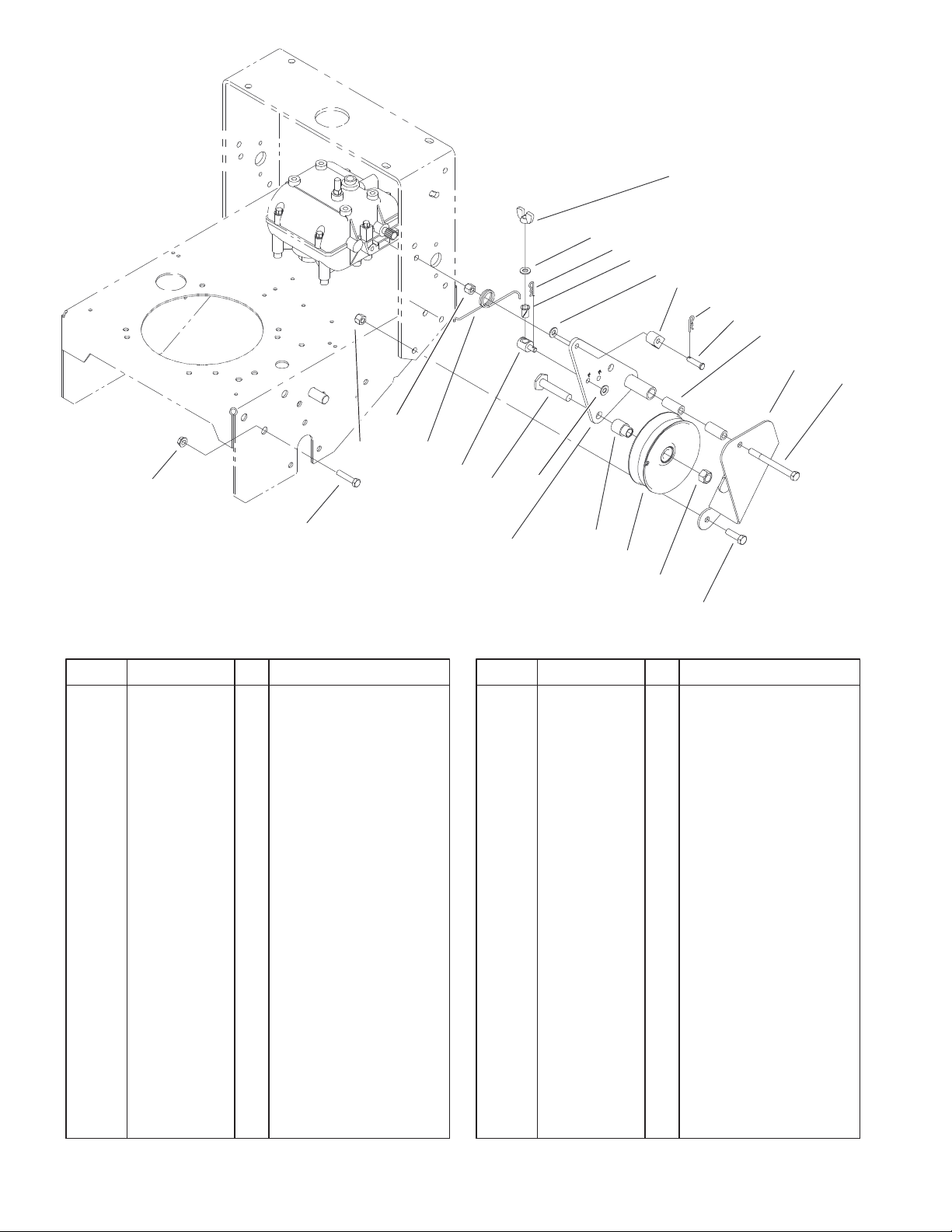
Wheel Drive and Brake System Assembly
DescriptionPart No. Qty.Ref. No. DescriptionPart No. Qty.Ref. No.
1 105–4652–01 2 Brake Link ASM
2 105–4651–01 2 Plate–Link, Brake
3 105–4667–01 1 LH Brake Arm ASM
4 105–4668–01 1 RH Brake Arm ASM
5 3290–307 2 Pin–Hair
6 51–4580 2 Rod–Brake
7 32151–40 2 Ring–Retaining
8 32151–56 2 Ring–Retaining,
External
9 32151–72 4 Ring–Retaining
10 1–323261 2 Drum–Brake
11 104–8152 2 Belt–Drive, Traction
12 51–4170 8 Spacer–Pulley
13 51–4160–03 4 Pulley–Wheel
14 1–413333 2 Hub–Wheel W/Cups
15 3296–29 8 Nut–Lock, NI
16 254–72 4 Bearing–Cup, Tapered
17 254–94 4 Bearing–Cone, Taper
19 242–50 8 Nut–Lug
20 241–119 2 Cap–Dust
21 1–809082 2 Nut–SHH
22 1–523157 2 Washer–Spacer
23 1–633926 8 Stud–Wheel
24 302–19 2 Fitting–Grease
25 1–323262 2 Band–Brake
26 322–8 8 Screw–HH
24
34:2
23
22
21
34:3
Sheet No.: 8
20
27 1–543511 2 Seal–Grease
28 104–1197 2 Spacer–Wheel
29 1–806800 2 Pin–Cotter
30 3234–11 6 Screw–HHF
31 104–1196–01 1 Axle ASM
32 32128–21 6 Nut–HF
34 104–1198 2 Wheel and Tire ASM
34:1 104–6320 1 Tire
34:2 104–1199 1 Wheel
34:3 232–27 1 Stem–Valve
19
8
2
1
4
3
5
6
7
8
3326–859
16
21
20
19
18
17
9
10
11
12
13
14
15
Sheet No.: 9
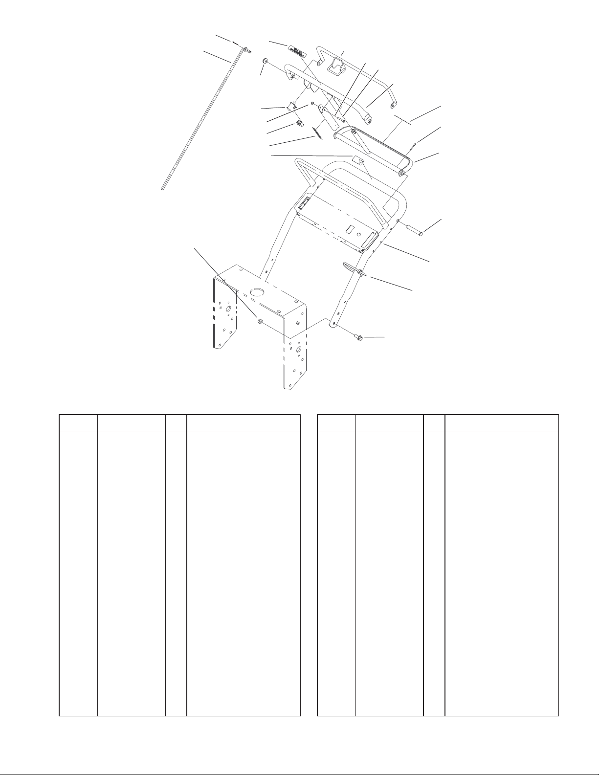
Handle Assembly
DescriptionPart No. Qty.Ref. No. DescriptionPart No. Qty.Ref. No.
1 82–7631 2 Rod–Control
2 3272–4 2 Pin–Cotter
3 237–141 2 Grommet–Rubber
4 82–2290 1 Decal–Bar, Control
5 82–7680–03 1 Bail
6 51–4850–03 1 Lever–Brake, Parking
7 32105–1 1 Screw–SHH
8 82–7690–03 1 Bar–Control
9 82–2280 1 Decal–Handle,
Reverse
10 3272–11 2 Pin–Cotter
11 99–8501–03 1 Control–Pivot
12 283–55 2 Pin–Clevis
13 67–6440–03 1 Handle–Upper
14 3290–378 1 Tie–Cable
15 3234–11 4 Screw–HHF
16 32128–21 4 Nut–HF
17 98–4387 1 Decal–Protection, Ear
18 52–2010 1 Decal–Lever, Parking
19 218–595 1 Connector–Body
20 3296–2 1 Nut–Lock
21 82–2190 1 Switch–Bail
9
3326–859
22
21
20
19
14
1
7
17
9
2
15:2
15
4
15:1
6
8
10
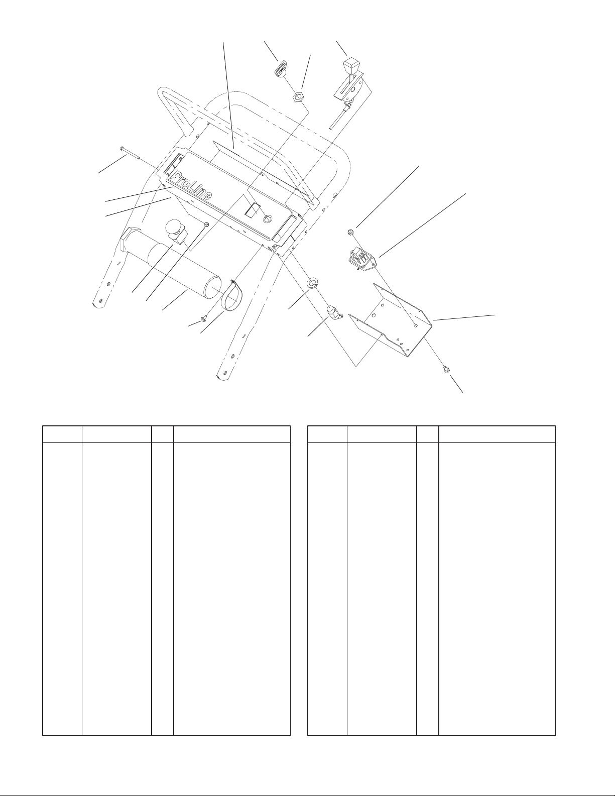
Control Panel Assembly
DescriptionPart No. Qty.Ref. No. DescriptionPart No. Qty.Ref. No.
1 105–0884 1 Decal–Danger
2 63–8360 2 Key–Ignition
4 100–6450 1 Control–Throttle
6 3296–42 1 Nut–Lock, NI
7 74–0720 1 Tube–Manual
8 104–8141 1 Module–Delay
9 2412–120 2 R–Clamp
10 93–1187–03 1 Panel–Bottom
11 321–2 1 Screw–HH
14 3296–2 4 Nut–Lock
15 29–5560 1 Switch–On/Off
15:1 218–461 1 Nut–HH
15:2 3254–5 1 Washer–Lock, Internal
17 32104–76 4 Screw
19 104–8140 1 Switch–PTO
20 104–8177–03 1 Panel–Control
21 104–8180 1 Decal–Panel, Control
22 32105–14 4 Screw
11
Sheet No.: 10
10
4
3
2
1:2
1
5
6
22
23
7
5
8
9
10
10
11
3326–859
21
15:4
15:3
21
15:2
20
17
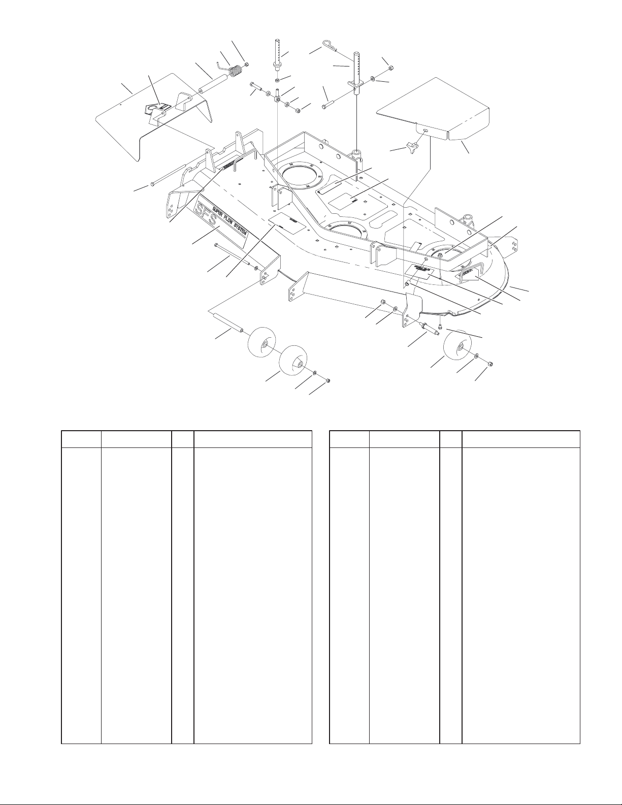
Deck Assembly
DescriptionPart No. Qty.Ref. No. DescriptionPart No. Qty.Ref. No.
1 104–7753 1 Deflector ASM
1:2 54–9220 1 Decal–Danger
2 104–8555 1 Spacer–Mounting,
Deflector
3 104–8554 1 Spring–Torsion
4 3296–29 2 Nut–Lock, NI
5 323–10 4 Screw–HH
6 105–0832 2 Link–Support
7 3220–3 2 Nut–Jam
8 1–613204 2 Balljoint
9 104–1156 4 Spacer
10 3296–39 12 Nut–Lock, NI
11 3256–24 10 Washer–Flat
12 104–8587 2 Knob
13 104–8118–01 1 Cover–Belt, Right
14 104–8117–01 1 Cover–Belt, Left
15 104–6394 1 Deck ASM
15:2 66–1340 1 Decal–Danger
15:3 98–5953 1 Decal–Sfs
15:4 104–8569 1 Decal–Warning,
Deflector
15:5 67–5360 3 Decal–Danger
15:6 104–8186 1 Decal–Routing, Belt
15:7 68–8340 1 Decal–Torque
15:8 43–8480 1 Decal–Danger
15:9 105–0840 1 Decal–Scalp, Anti
19
12
15:5
15:6
10
11
18
17
4
11
13 RH
14 LH
10
25
16
24
15:9
15:7
15
15:8
Sheet No.: 2
16 32148–10 2 Insert–Threaded
17 68–2730 6 Wheel–Gage
18 99–2842 4 Spacer–Wheel
19 3256–23 2 Washer–Flat
20 98–5967 1 Spacer–Wheel
21 322–50 2 Screw–Cap
22 3290–256 6 Pin–Hair
23 105–0831 2 Rod ASM
24 32128–20 7 Nut–HF
25 322–1 7 Screw–HH
11
 Loading...