

Page 1

Form No. 3325-387 Rev A
Operator’s Manual
®
Groundsmaster®228-D
Traction Unit
Model No. 30241—210000001 and Up
English
Page 2

Contents 2
Introduction 3
Safety 3
Safe Operating Practices 3
Toro Mower Safety 5
Safety and Instruction Decals 8
Specifications 12
Installing Rear Weights 14
Before Operating 15
Check the Engine Oil 15
Check the Cooling System 15
Check Hydraulic System Fluid 15
Fill the Fuel Tank 16
Controls 17
Operation 20
Starting/Stopping the Engine 20
Bleeding the Fuel System 20
Checking the Interlock System 21
Operating Characteristics 22
Pushing or Towing the Traction Unit 22
Maintenance 23
Recommended Maintenance Schedule 23
Fluid Specifications/Change Intervals 24
Service Interval Charts 24
Daily Maintenance Checklist 25
General Air Cleaner Maintenance 27
Servicing the Air Cleaner 27
Cleaning the Radiator and Screen 28
Changing the Engine Oil and Filter 28
Servicing the Fuel System 28
Replacing the Fuel Pre Filter 29
Bleeding Air from Injectors 30
Alternator Belt 30
Adjusting the Throttle 30
Power Take-Off Belt 30
Power Take-Off Clutch Adjustment 31
Adjusting the Transmission for Neutral 31
Adjusting the Parking Brake
Interlock Switch 32
Changing the Hydraulic Oil and Filter 33
Adjusting the Service Brakes 34
Servicing the Battery 34
Wiring Harness Service 34
Fuses 34
Storage 35
2
Contents
2001 by The Toro Company 8111
Lyndale Avenue South
Bloomington, MN 55420-1196
All Rights Reserved
Printed in the USA
Page 3
Read this manual carefully to learn how to operate
and maintain your product properly. The information
in this manual can help you and others avoid injury
and product damage. Although Toro designs and
produces safe products, you are responsible for
operating the product properly and safely.
Whenever you need service, genuine Toro parts, or
additional information, contact an Authorized Service
Dealer or Toro Customer Service and have the model
and serial numbers of your product ready. Figure 1
illustrates the location of the model and serial
numbers on the product.
Figure 1
1. Location of the model and serial numbers
Write the product model and serial numbers in the
space below:
This manual identifies potential hazards and has
special safety messages that help you and others avoid
personal injury and even death. Danger, Warning, and
Caution are signal words used to identify the level of
hazard. However, regardless of the hazard, be
extremely careful.
Danger signals an extreme hazard that will cause
serious injury or death if you do not follow the
recommended precautions.
Warning signals a hazard that may cause serious
injury or death if you do not follow the recommended
precautions.
Caution signals a hazard that may cause minor or
moderate injury if you do not follow the
recommended precautions.
Safety
This machine meets or exceeds the B71.4 1999
specifications of the American National Standards
Institute when weights are installed according to
chart on page 14.
Note: The addition of attachments made by other
manufacturers that do not meet American National
Standards Institute certification will cause
noncompliance of this machine.
Improper use or maintenance by the operator or
owner can result in injury. To reduce the potential
for injury, comply with these safety instructions
and always pay attention to the safety alert symbol
, which means CAUTION, WARNING, or
DANGER—personal safety instruction.” Failure
to comply with the instruction may result in
personal injury or death.
Safe Operating Practices
Training
• Read the Operator’s Manual and other training
material. If the operator(s) or mechanic(s) cannot
read the language of the manual, it is the owner’s
responsibility to explain this material to them.
• Become familiar with the safe operation of the
equipment, operator controls, and safety signs.
• All operators and mechanics should be trained.
The owner is responsible for training the users.
• Never let children or untrained people operate or
service the equipment. Local regulations may
restrict the age of the operator.
• The owner/user can prevent and is responsible
3
Introduction
Model No. __________________________
Serial No. ___________________________
Page 4

for accidents or injuries occurring to himself or
herself, other people or property.
Preparation
• Evaluate the terrain to determine what
accessories and attachments are needed to
properly and safely perform the job. Only use
accessories and attachments approved by the
manufacturer.
•Wear appropriate clothing including hard hat,
safety glasses and ear protection. Long hair, loose
clothing or jewelry may get tangled in moving
parts.
• Inspect the area where the equipment will be
used and remove all objects such as rocks, toys
and wire that can be thrown by the machine.
• Use extra care when handling diesel and other
fuels. They are flammable and vapors are
explosive.
• Use only an approved container
• Never remove the fuel cap or add fuel with
the engine running. Allow the engine to cool
before refueling. Do not smoke.
• Never refuel or drain the machine indoors.
• Check that operator’s presence controls, safety
switches and shields are attached and functioning
properly. Do not operate unless they are
functioning properly.
Operation
• Never run an engine in an enclosed area.
• Only operate in good light, keeping away from
holes and hidden hazards.
• Be sure all drives are in neutral and the parking
brake is engaged before starting the engine. Only
start the engine from the operator’s position. Use
seat belts, if provided.
• Slow down and use extra care on hillsides. Be
sure to travel in the recommended direction on
hillsides. Turf conditions can affect the machine’s
stability. Use caution while operating near
drop–offs.
•Slow down and use caution when making turns
and when changing directions on slopes.
• Never raise the deck with the blades running.
• Never operate with the power take-off shield, or
other guards not securely in place. Be sure all
interlocks are attached, adjusted properly, and
functioning property.
• Do not change the engine governor setting or
overspeed the engine.
• Stop on level ground, lower the implements,
disengage the drives, engage the parking brake
(if provided), and shut off the engine before
leaving the operator’s position for any reason.
• Stop the equipment and inspect the blades after
striking objects or if an abnormal vibration
occurs. Make necessary repairs before resuming
operations.
• Keep your hands and feet away from the cutting
units.
• Look behind and down before backing up to be
sure of a clear path.
• Never carry passengers and keep pets and
bystanders away.
•Slow down and use caution when making turns
and crossing roads and sidewalks. Stop the
blades if not mowing.
• Do not operate the mower under the influence of
alcohol or drugs
• Use care when loading or unloading the machine
into a trailer or truck
• Use care when approaching blind corners,
shrubs, trees, or other objects that may obscure
4
Page 5

vision.
Maintenance and storage
• Disengage the drives, lower the implement, set
the parking brake, stop the engine and remove
the key. Wait for all movement to stop before
adjusting, cleaning or repairing.
• Clean grass and debris from the cutting units,
drives, mufflers, and engine to help prevent fires.
Clean up oil or fuel spillage.
• Let the engine cool before storing and do not
store near flame.
• Do not store fuel near flames or drain indoors.
• Park the machine on level ground. Never allow
untrained personnel to service the machine.
• Use jack stands to support components when
required.
• Carefully release pressure from components with
stored energy.
• Disconnect the battery before making any
repairs. Disconnect the negative terminal first
and the positive last. Reconnect positive first and
negative last.
• Use care when checking the blades. Wrap the
blade(s) or wear gloves, and use caution when
servicing them. Only replace the blades. Never
straighten or weld them.
• Keep your hands and feet away from moving
parts. If possible, do not make adjustments with
the engine running.
• Charge batteries in an open well ventilated area,
away from spark and flames. Unplug charger
before connecting or disconnecting from the
battery. Wear protective clothing and use
insulated tools.
• Keep all parts in good working condition and all
hardware tightened. Replace all worn or damaged
decals.
Toro Mower Safety
This product is capable of amputating hands and feet
and throwing objects. Always follow all safety
instructions to avoid serious injury or death.
This product is designed for cutting and recycling
grass. Any use for purposes other than these could
prove dangerous to user and bystanders.
General Operation
• Allow only responsible adults who are familiar
with the instructions to operate the machine.
• Be sure the area is clear of other people before
mowing.Stop the machine if anyone enters the
area.
• Do not mow in reverse unless absolutely
necessary. Always look down and behind before
and while backing.
• Slow down before turning. Sharp turns on any
terrain may cause loss of control.
•Turn off the blades when not mowing.
• Keep hands, feet, hair and loose clothing away
from attachment discharge area, underside of
mower and any moving parts while the engine is
running.
• Mow only in daylight or good artificial light.
•Watch for traffic when operating near or crossing
roadways.
• Do not touch equipment or attachment parts
which may be hot from operation. Allow to cool
before attempting to maintain, adjust or service.
• Before operating a machine with roll over
protection be certain the seat belts are attached
and seat is latched to prevent the seat from
pivoting forward.
5
Page 6

• Use only Toro-approved attachments. Warranty
may be voided if used with unapproved
attachments.
Slope Operation
Slopes and ramps are a major factor related to loss-ofcontrol and tip-over accidents, which can result in
severe injury or death. All slopes and ramps require
extra caution. If you cannot back up the slope or if
you feel uneasy on it, do not mow it.
DO
• If you must ascend a steep slope, back up the hill,
and drive forward down the hill, keeping the
machine in gear.
• Remove obstacles such as rocks, tree limbs, etc.
from the mowing area. Watch for holes, ruts or
bumps, as uneven terrain could overturn the
machine. Tall grass can hide obstacles.
• Use slow speed so that you will not have to stop
while on the slope.
• Follow the manufacturer’s recommendations for
wheel weights or counterweights to improve
stability.
• Use extra care with other attachments. These can
change the stability of the machine.
• Keep all movement on slopes slow and gradual.
Do not make sudden changes in speed or
direction.
•Avoid starting or stopping on a slope. If the tires
lose traction, disengage the blades and proceed
slowly straight down the slope. Avoid raising the
side decks on a slope.
• When operating the machine on slopes, banks or
near drop offs, always have roll-over protection
installed.
• When operating a machine with roll-over
protection always use seat belt.
• Be certain that the seat belt can be released
quickly if the machine is driven or rolls into
ponds or water.
• Check carefully for overhead clearances (i.e.,
branches, doorways, electrical wires) before
driving under any objects and do not contact
them.
DO NOT
• Do not mow slopes exceeding 15 degrees.
•Avoid turning on slopes. If you must turn, turn
slowly and gradually downhill, if possible.
• Do not mow near drop-offs, ditches, or
embankments. The machine could suddenly turn
over if a wheel goes over the edge of a cliff or
ditch, or if an edge caves in.
• Do not mow on wet grass. Reduced traction
could cause sliding.
• Do not try to stabilize the machine by putting
your foot on the ground.
Service
• Never store the machine or fuel container inside
where there is an open flame, such as near a
water heater or furnace.
• Keep nuts and bolts tight, especially the blade
attachment bolts. Keep equipment in good
condition.
• Never tamper with safety devices. Check safety
systems for proper operation before each use.
• Use only genuine replacement parts to ensure
that original standards are maintained.
• Check brake operation frequently. Adjust and
service as required.
• Battery acid is poisonous and can cause burns.
Avoid contact with skin, eyes and clothing.
Protect your face, eyes and clothing when
6
Page 7

working with a battery.
• Battery gases can explode. Keep cigarettes,
sparks and flames away from the battery.
• Hydraulic fluid escaping under pressure can
penetrate the skin and cause injury. Use
cardboard or paper to find hydraulic leaks. Never
use your hands.
Sound Pressure Level
This unit has an equivalent continuous A-weighted
sound pressure at the operator ear of: 90 dB(A), based
on measurements of identical machines per Directive
84/538/EEC and amendments.
Sound Power Level
This unit has a sound power level of: 105 dB(A) 1
pW, based on measurements of identical machines per
Directive 84/538/EEC and amendments.
Vibration Level
Hand-Arm
This unit does not exceed a vibration level of 2.5 m/s
2
at the hands based on measurements of identical
machines per ISO 5349 procedures.
Whole Body
This unit does not exceed a vibration level of 0.5
m/s2at the posterior based on measurements of
identical machines per ISO 2631 procedures.
7
Page 8
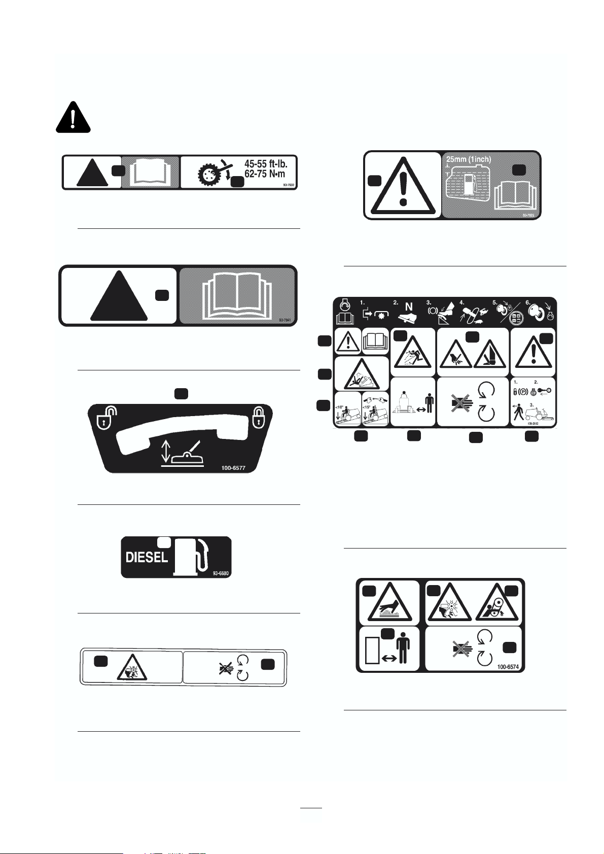
93-7830
1. Danger—See operator’s manual
2. Wheel torque specifications
93-7841
1. Danger—See operator’s manual
100-6577
1. Lock—Unlock the deck service lock
93-6680
1. Diesel fuel
93-7272
1. Fan blades can cause injury
2. Stay away from moving parts
93-7822
1. Danger
2. See Operator’s manual
3. Fill the fuel tank to 1” from bottom of the filler neck
105-2512
1. Read operator’s manual for starting instructions
2. Danger—Read operator’s manual
3. Tipping hazard—Go slow and avoid sharp turns on
slopes to avoid rollover. The deck must be lowered when
going down slopes for steering control. Always wear seat
belts with roll-over protection.
4. Thrown object hazard—keep bystanders away
5 Cutting hazard to hands or feet—stay away from rotating
blades or moving parts.
6. Danger—set the parking brake, stop the engine and
remove the key before leaving the operator’s position.
100-6574
1. Hot surface stay away
2. Stay away from moving parts
8
Safety and Instruction Decals
Safety decals and instructions are easily visible to the operator and are located near any area of potential
danger. Replace any decal that is damaged or lost.
1
2
1
1
1
1
2
1
2
1
2
3
3
4
4
5
5
6
6
1
1
2
2
2
Page 9
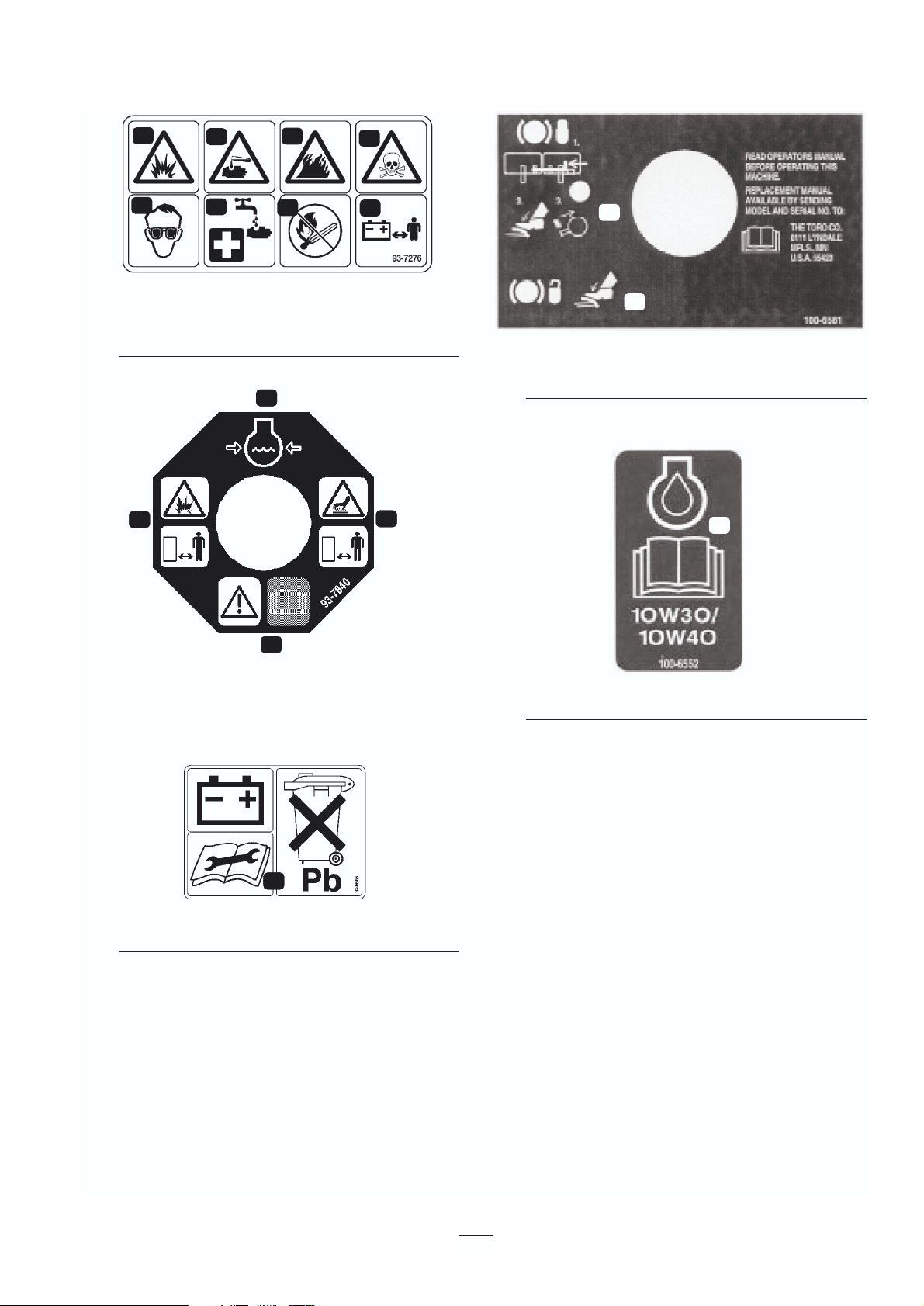
93-7276
1. Explosion hazard—wear eye protection.
2. Caustic liquid hazard—flush with water and seek first aid.
3. Fire hazard — no sparks, flame, or smoking
4. Poison—keep children a safe distance from the battery.
93-7840
1. Coolant level
2. Hot surface—keep a safe distance
3. Danger—rear the operator’s manual
4. Explosion hazard—stay away
93-6668
1. The battery contains lead. Do not throw it in the garbage.
100-6581
1. To lock parking brake—Latch pedals together, apply
brake pedals and pull up on knob
2. To unlock parking brake—step on brake pedals
100-6552
1. Refer to Operator’s Manual for engine oil specifications
9
1
3
4
2
1
1
1
2
2
3
3
4
4
1
2
1
Page 10
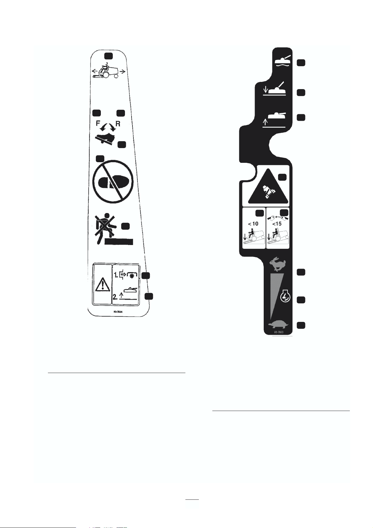
93-7834
1. No step
2. Traction pedal
3. Traction—forward
4. Traction—reverse
5. Danger—Shut off power take-off prior to raising decks
6. Danger—Do not operate decks when they are in raised
position
93-7833
1. Throttle control
2. Throttle—fast
3. Throttle—slow
4. Tipping hazard—Lower the deck when going down slopes
greater than 10 degrees
5. Tipping hazard—Lower the deck when going down slopes
greater than 10 degrees
6. Danger—tipping hazard
7. Lift lever—raise position
8. Lift lever—lower position
9. Lift lever—float position
10
1
1
3
3
2
4
5
6
1
2
3
4
5
6
7
8
9
Page 11
11
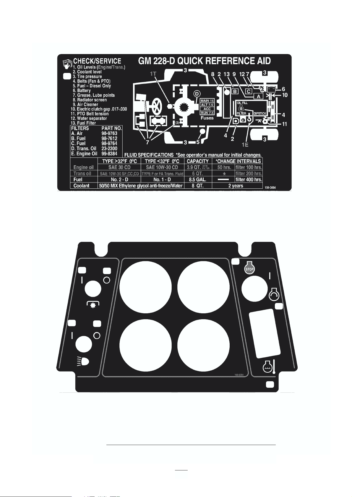
Part No. 104-3484
1. See the operator’s manual
Part No. 105-0054
1. Headlights—off
2. Headlights—on
3. Power take-off—off
4. Power take-off—on
5. Engine coolant temperature
6. Engine—start
7. Engine—stop
1
1
2
3
4
5
6
7
Page 12

12
Specifications
Note: Specifications and design subject to change without notice.General Specifications
Engine Kubota three-cylinder, 4-cycle, liquid-cooled diesel engine. 26 hp @ 3000. Engine
governed to 3200–3250 rpm high idle, no load.
Air Cleaner Heavy-duty remote mounted.
Fuel Tank Capacity 8.5 gal. (32 l) Equipped with a fuel filter/water separator to capture water in the fuel.
Fuel Pump 12-volt electric (transistor type) w/replaceable fuel filter.
Cooling System 7 qt (6.6 l) capacity. Remote-mounted expansion tank 1 qt (0.946 l) capacity. System
contains a 50/50 mix of ethylene glycol anti-freeze and water. Front mounted air/oil
cooler used to cool hydraulic oil for the hydrostatic transmission.
Electrical 12 volt with 530 cold cranking amps at 0° F and 75-minute reserve capacity at 80° F.
Drive Coupling Transmission driven by steel shaft with flexible rubber couplings at each end.
Transmission Hydrostatic, U-type. Implement Relief Setting—700–800 psi (4,826–5,516 kPa).
Hydraulic Filter Replaceable 25-micron filter mounted directly to the transmission.
Drive Axle The front axle serves as a hydraulic fluid reservoir and mates directly with the
transmission. Approximately 6 qt (5.7 l) capacity.
Brakes Mechanical drum-type. Individually controlled by two pedals connected by cable and
conduit for steering assist. Pedals may be latched together for two wheel braking. Lever
provided for parking brake.
Tires Front Tires—23 x 8.50-12, Rear Tires—16 x 6.50-8. All tires: 4-ply rating, tubeless
type. Pressure—20 psi (138 kPa).
Ground Speed 0–16 kmh forward and reverse.
Main Frame Frame is welded, formed steel.
Instrumentation Fuel gauge, water temperature gauge, hour meter and warning lights for high
temperature shutdown, oil pressure, amperage and glow plug are mounted on the
console.
Controls Throttle, power take-off switch, parking brake, implement lift, implement lift lock,
ignition switch and high temperature override switch are all hand-operated.
Forward/reverse traction pedal and turning brakes are foot-operated.
Power take-off drive The power take-off shaft is clutched by a belt directly from the engine output shaft. The
power take-off shaft engaged by an electric clutch/brake assembly. Power take-off
speed—2200 RPM@3250 RPM engine speed.
Page 13

Measurements
Length 208 cm (82 in.)
Width (Rear Wheels) 119.4 cm (47 in.)
Height 127 cm (50 in.)
Weight 442 kg (1185 lb.)
Optional Equipment
52” Side Discharge Cutting Unit Model No. 30555
52” Rear Discharge Cutting Unit Model No. 30568
62” Side Discharge Cutting Unit Model No. 30551
62” Guardian Recycler Cutting Unit Model No. 30569
72” Side Discharge Cutting Unit Model No. 30553
48” V-Plow Kit Model No. 30750
V-Plow Mounting Kit Model No. 30749*
Arm Rest Kit Model No. 30707
Rear Discharge Shield Kit Model No. 30578
Rear Weight Box Kit Part No. 24-5780
Grass Collection System Model No. 30502**
Wide Tires w/rim
23 x 10.5-12, 4 ply Part No. 62-7020
23 x 10.5-12, 6 ply Part No. 69-9870
Wheel Weights-50 lbs. (23kg.) Part No. 11-0440
Rear Weight Kit—70 lbs. (32 kg.) Part No. 24-5780
Weight Kit—20 lbs. Part No. 92-8763
Tire Chains (Front) Part No. 11-0390
Standard Seat Kit Model No. 30624
Deluxe Seat Kit Model No. 30625
*Required with 30750 V-plow. Tire chains, part no.
11-0390 recommended.
** 52” Blower Kit (for Model 30555 deck) or Model
30506 62” Blower Kit (for Model 30551 deck) can be
used with either Model No. 30504, 9 cu. ft. Hopper
Kit or Model No. 30505, 15 cu. ft. Hopper Kit.
13
Implement Connection Universal joint and telescoping shaft assembly.
Lift Cylinders Two with 2 in. (51 mm) bore, 3.5 in. (89 mm) stroke.
Interlock Switches Prevent engine starting if the traction pedal or power take-off switch are engaged. Stops
the engine if the operator leaves the seat with either the traction pedal or power take-off
switch engaged. Stops the engine if the traction pedal is engaged with parking brake
engaged.
Page 14

14
Two-Wheel Drive Groundsmaster 228-D Series traction units comply with ANSI B71.4-1999 Standard when
equipped with rear weight. Use chart below to determine combinations of weight required. Order parts from your
local Authorized Toro Distributor.
* 75 lb. wheel weight (included with 15 cu. ft. hopper) required on the left wheel
1
Rear
Weight
Required
Left Side
Weight
Required
Weight Description
Quantity
Weight Part
Number
52” Rear Discharge
Deck (Model 30568) or
52” Side Discharge
Deck
52” Side Discharge
Deck with 9 cu. ft.
Hopper
52” Side Discharge
Deck with 15 cu. ft.
Hopper
Rear Weight Kit
& Weight Kit-20 lb.
1
1
10 lbs.
0 lbs.
24-5780
& 92-8763
24-5790
325-8
3253-7
3-8847
3217-9
92-8763
92-8763 Weight Kit – 20 lb.
215 lbs.
0 lbs.
75 lb.*
77-6700 &
92-9670 &
24-5780
0 lbs.
0 lbs.
20 lbs.
0 lbs.
0 lbs.
0 lbs.
55 lbs.
* 77-6700 75 lb. Wheel Weight
62” Side Discharge
Deck (Model 30564) or
62” Side Discharge
Deck with 9 cu. ft.
Hopper
62” Side Discharge
Deck with 15 cu. ft.
Hopper
62” Guardian Recycler
Deck (Model 30569)
72” Side Discharge
Deck (Model 30575)
Rear Weight—35 lb.
Capscrew-
1
⁄2-13 x 2”
Lockwasher-
1
⁄2
Spacer
Nut-
1
⁄2
& Weight Kit-20 lb
75 lb. Wheel Weight
& Bracket Kit
& Rear Weight Kit
1
1
1
70 lbs
90 lbs
-- --
1
2
2
2
2
1
24-5780
Installing Rear Weights
Page 15

Check the Engine Oil
The engine is shipped with 4 qt (3.8 l) of oil in the
crankcase; however, check the oil level before and
after you first start the engine.
1. Park the machine on a level surface, stop the
engine and remove the key from the ignition
switch. Open the hood.
2. Remove the dipstick (Fig. 2), wipe it clean and
reinstall it. Remove it again and check the oil
level. The level should be up to the FULL mark
on the dipstick
Figure 2
1. Dipstick
2. Oil fill
3. If the oil is below the FULL mark, remove the fill
cap and add SAE 10W-30 CD, CE, CF, CF-4 or
CG-4 classification oil until the level reaches the
FULL mark on the dipstick. DO NOT
OVERFILL.
4. Install the oil fill cap and close the hood.
Check the Cooling System
Clean debris from the screen and radiator/oil cooler
daily, more often if conditions are extremely dusty
and dirty; refer to Engine Cooling System.
The cooling system is filled with a 50/50 solution of
water and permanent ethylene glycol anti-freeze.
Check the level of coolant in the expansion tank at the
beginning of each day before you start the engine.
Cooling system capacity is 7 quarts (6.6 l).
1. Check the level of coolant in the expansion tank.
Coolant level should be between the marks on
the side of the tank.
Figure 3
1. Expansion tank
2. If the coolant level is low, remove the expansion
tank cap and replenish the system. DO NOT
OVERFILL.
3. Install the expansion tank cap.
Check Hydraulic System Fluid
The hydraulic system will operate with any highquality detergent oil having the American Petroleum
Institute—API—“service classification” SF, CC or
CD. Oil viscosity—weigh —must be selected
according to anticipated ambient temperature.
Temperature/viscosity recommendations are:
15
Before Operating
if the engine has been running, pressurized hot
coolant can escape and cause burns when you
remove the radiator cap.
CAUTION
1
1
2
Page 16

Expected Ambient
Temperature
(Extreme) over 32° C SAE 30, Type SF, CC or CD
engine oil
(Normal) 4–37° C SAE 10W-30 or 10W-40,
Type SF,CC or CD engine oil
(Cool) –1 to 10° C SAE 5W-30, Type SF, CC or
CD engine oil
(Winter) Below –1° C Type “F” or “FA” ATF
Automatic Transmission Fluid
Note: Do not mix engine oil and automatic
transmission fluid or hydraulic component damage
may result. When changing fluids, also change the
transmission filter. DO NOT USE DEXRON II ATF.
The transmission and axle housing are shipped from
the factory with approximately 5 quarts (4.7 l) of SAE
10W-30 engine oil. However, check the level of
transmission oil before first starting the engine and
daily thereafter.
1. Position the machine on a level surface. Place all
controls in neutral position and start the engine.
Run the engine at lowest possible RPM to purge
the system of air. DO NOT ENGAGE the power
take-off. Turn the steering wheel several times
fully to the left and right. Raise the cutting unit to
extend the lift cylinders, aiming the wheels
straight forward, and stop the engine.
2. Remove the dipstick cap (Fig. 4) from the filler
neck and wipe it with a clean cloth. Screw the
dipstick cap finger-tight onto the filler neck; then
remove it and check the level of fluid. If the level
is not within
1
⁄
2 inch (13 mm) from the groove in
the dipstick (Fig. 4), add SAE 10W-30 engine oil,
or, if used, automatic transmission fluid to raise
the level to groove mark. Do not overfill.
When adding transmission fluid to
the hydraulic system, use a funnel with a fine
wire screen—200 mesh or finer—and make sure
the funnel and transmission fluid are
immaculately clean. This prevents accidentally
contaminatimg the hydraulic system.
3. Thread the dipstick fill cap finger-tight onto the
filler neck. It isn’t necessary to tighten the cap
with a wrench.
4. Check all hoses and fittings for leaks.
Figure 4
1. Hydraulic system reservoir fluid/add dipstick cap
Fill the Fuel Tank
1. Using a clean cloth, clean area around the fuel
tank cap.
2. Remove the cap from the fuel tank (Fig. 5).
3. Fill the 8.5 gallon (32 l) tank to within 1 inch (25
Important
Recommended
Viscosity and Type
16
Under certain conditions, diesel fuel and fuel vapors
are highly flammable and explosive. A fire or
explosion from fuel can burn you and others and can
cause property damage.
• Use a funnel and fill the fuel tank outdoors, in
an open area, when the engine is off and is cold.
Wipe up any fuel that spills.
• Do not fill the fuel tank completely full. Add
fuel to the fuel tank until the level is 1 in. (25
mm) below the bottom of the filler neck. This
empty space in the tank allows the fuel to
expand.
• Never smoke when handling fuel, and stay
away from an open flame or where fuel fumes
may be ignited by a spark.
• Store fuel in a clean, safety-approved container
and keep the cap in place.
CAUTION
1
Page 17

Service Brakes
The left and right brake pedals (Fig. 6) are connected
to the left and right front wheels. Since both brakes
work independently, the brakes can be used to turn
sharply or to increase traction if one wheel tends to
slip while operating on certain slope conditions.
However, wet grass or soft turf can be damaged when
brakes are used to turn sharply. To make a “quickstop”, depress both brake pedals together. Always lock
the brakes together when transporting the traction
unit.
Figure 6
1. Parking brake knob
2. Right brake pedal
3. Left brake pedal
Figure 7
1. Left brake pedal
2. Right brake pedal
3. Lock arm
Parking Brake
Whenever the engine is shut off, the parking brake
must be engaged to prevent accidental movement of
the machine. To engage the parking brake, push the
lock arm (Fig. 7) on so that it locks together with the
right pedal. Next, push down fully on both pedals and
pull parking brake knob out (Fig. 6) then release the
pedals. To release the parking brake, depress both
pedals until the parking brake knob retracts. Before
starting the engine, however, the lock arm may be
disengaged from the left brake pedal so both pedals
work independently with each front wheel
17
mm) from the bottom of the filler neck with
diesel fuel.
4. Install the fuel tank cap tightly after filling tank.
Figure 5
1. Fuel tank cap
Controls
1
1
1
2
3
2
3
Page 18

Traction Pedal
The traction pedal (Fig. 8) has two functions: to make
the machine move forward, and to make it move
backward. Depress the top of the pedal to move
forward and bottom of the pedal to move rearward.
Ground speed is proportionate to how far you depress
the pedal. For maximum ground speed, the traction
pedal must be fully depressed while the throttle is in
the FAST position. Maximum speed forward is 10
mph (16 Km/hr) (approx.). To get maximum power
with a heavy load or when climbing a hill, have the
throttle in the FAST position while depressing the
traction pedal slightly to keep engine rpm high. When
engine rpm begins to decrease, release the traction
pedal slightly to allow rpm to increase.
Figure 8
1. Traction pedal
Hydraulic Lift Lever
The hydraulic lift lever (Fig. 9) has three positions:
FLOAT, TRANSPORT and RAISE. To lower the
cutting unit to the ground, move the lift lever forward
into the notch in the seat platform—FLOAT. Use the
FLOAT position for mowing and when the machine is
not in operation. To raise the cutting unit, pull the lift
lever rearward to the RAISE position.
After the cutting unit is raised, let the lift lever move
to the TRANSPORT position. The cutting unit must
be raised when driving from one work area to another.
Figure 9
1. Hydraulic lift lever
2. Power take-off switch
3. Temperature gauge
4. Fuel gauge
5. Ignition key switch
6. Temperature override switch
7. Throttle
8. Hour meter
9. Engine coolant temperature
10. Glow plug indicator
11. Charge indicator
12. Oil pressure indicator
13. Lift lever lock
Power Take-Off Switch
Pull up on the sleeve on the toggle switch handle and
move handle to ON to engage the power take-off
clutch (Fig. 9). Pull up on the sleeve and move the
handle to OFF to disengage the power take-off clutch.
The only time the power take-off switch should be in
the ENGAGE position is when the implement is
down, in operating position and ready to begin
operation.
Temperature Gauge
The temperature gauge (Fig. 9) registers the
temperature of the coolant in the cooling system. If
coolant temperature becomes too high, the engine will
shut off automatically.
Fuel Gauge
The fuel gauge (Fig. 9) indicates the quantity of fuel
remaining in the fuel tank.
Ignition Key Switch
Three positions: OFF, ON/Preheat and START
(Fig. 9).
18
Never raise the cutting unit while the blades are
rotating because it is hazardous.
CAUTION
1
1
2
3
4
5
6
7
13
12
11
10
9
8
Page 19

Temperature Override Switch
Press and hold the over-ride switch (Fig. 9) to start the
engine after a high-temperature shut down. Use only
for emergency operation.
Throttle
The throttle (Fig. 9) is used to operate the engine at
various speeds. Moving the throttle forward increases
engine speed—FAST; rearward decreases engine
speed—SLOW. The throttle controls the speed of the
cutter blades and, with the traction pedal, controls the
traction unit’s ground speed.
Hour Meter
The hour meter (Fig. 9) registers accumulated hours
of engine operation.
Engine Coolant Temperature Warning
Light
The light illuminates and the engine shuts down when
coolant reaches an excessively high temperature
(Fig. 9).
Glow Plug Indicator
When lit, indicates that the glow plugs are on (Fig. 9).
Charge Indicator
Illuminates when the system’s charging circuit
malfunctions (Fig. 9).
Oil Pressure Warning Light
The oil pressure warning light (Fig. 9) glows when
engine oil pressure drops below a safe level. If low oil
pressure occurs, stop the engine and determine the
cause. Repair the damage before starting the engine
again.
Lift Lever Lock
Lock the lift lever (Fig. 9) in the raised position when
performing maintenance on the cutting unit.
Seat Adjusting Handle
To adjust the seat, loosen the adjusting knobs and
slide the seat to the desired position. Tighten the
knobs to lock the seat in place.
Seat Adjusting Handle—Deluxe Seat
To adjust the seat, move the lever on the left side
outward, slide the seat to the desired position and
release the lever so it will lock in that position.
19
Page 20

Note: Determine the left and right sides of the
machine from the normal operating position.
Starting/Stopping the Engine
the fuel system must be bled if any of
the following situation have occurred.
A. Initial start up of a new machine.
B. The engine has ceased running due to lack of
fuel.
C. Maintenance has been performed on fuel system
components; i.e., filter replaced, separator
serviced, etc.
Refer to Bleeding the Fuel System.
1. Ensure the parking brake is set, the power take-
off switch is in the OFF position and the lift lever
is in the TRANSPORT or FLOAT position.
Remove your foot from the traction pedal and
make sure it is in neutral.
2. Move the throttle control to the 1/2-speed
position.
3. Turn the ignition switch to the ON/Preheat
position. An automatic timer will control preheat
for 6 seconds. After preheat, turn the key to the
START position. CRANK THE ENGINE FOR
NO LONGER THAN 15 SECONDS. Release the
key when the engine starts. If additional preheat
is required, turn the key to the OFF position then
to the ON/preheat position. Repeat the process as
required.
4. Run the engine at idle speed or partial throttle
until the engine warms up.
Note: Move the throttle to the
1
⁄
2-speed position
when restarting a warm engine.
5. When the engine is started for the first time, or
after an engine oil change, or overhaul of the
engine, transmission or axle, operate the machine
in forward and reverse for one to two minutes.
Also operate the lift lever and power take-off
lever to assure proper operation of all parts. Turn
the steering wheel to the left and right to check
steering response. Then shut the engine off and
check fluid levels. Also check for oil leaks, loose
parts and any other noticeable malfunctions.
6. To stop the engine, move the throttle control
backward to the SLOW position, move the power
take-off switch to the OFF position and turn the
ignition key to OFF. Remove the key from the
switch to prevent accidental starting.
Bleeding the Fuel System
1. Park the machine on a level surface. Make sure
the fuel tank is at least half full.
Important
20
Operation
Shut the engine off and wait for all moving
parts to stop before checking for oil leaks, loose
parts or other malfunctions.
CAUTION
Under certain conditions, diesel fuel and fuel
vapors are highly flammable and explosive. A
fire or explosion from fuel can burn you and
others and can cause property damage.
• Use a funnel and fill the fuel tank
outdoors, in an open area, when the engine
is off and is cold. Wipe up any fuel that
spills.
• Do not fill the fuel tank completely full.
Add fuel to the fuel tank until the level is 1
in. (25 mm) below the bottom of the filler
neck. This empty space in the tank allows
the fuel to expand.
• Never smoke when handling fuel, and stay
away from an open flame or where fuel
fumes may be ignited by a spark.
• Store fuel in a clean, safety-approved
container and keep the cap in place.
DANGER
Page 21

2. Unlatch and raise the hood.
3. Open the air bleed screw on the fuel injection
pump (Fig. 10).
Figure 10
1. Fuel injection pump bleed screw
4. Turn the key in the ignition switch to the ON
position. The electric fuel pump will begin
operation, forcing air out around air bleed screw.
Leave the key in the ON position until a solid
stream of fuel flows out around the screw.
Tighten the screw and turn the key to OFF.
Note: Normally, the engine should start after
these bleeding procedures. However, if it doesn’t,
air may be trapped between the injection pump
and the injectors; refer to Bleeding Air from the
Injectors.
Checking the Interlock System
The purpose of the safety interlock system is to
prevent the engine from cranking or starting unless the
traction pedal is in neutral and the power take-off
switch is in the OFF position. Also, the engine will
stop when the power take-off control is engaged or the
traction pedal is depressed with operator off the seat
or when the parking brake is engaged.
1. Move the power take-off switch to the OFF
position and remove your foot from the traction
pedal.
2. Turn the ignition key to START. The engine
should crank. If the engine cranks, go to step 3.
If the engine does not crank, there may be a
malfunction in the interlock system.
3. Rise off the seat and engage the power take-off
switch while the engine is running. The engine
should stop within 2 seconds. If the engine stops,
the switch is operating correctly; go to step 4. If
the engine does not stop, there is a malfunction in
the interlock system.
4. Rise off the seat and depress the traction pedal
while the engine is running the power take-off
lever is disengaged. The engine should stop
within 2 seconds. If the engine stops, the switch
is operating correctly; go to step 5. If the engine
does not stop, there is a malfunction in the
interlock system.
5. Engage the parking brake. Depress the traction
pedal while the engine is running and the power
take-off lever is disengaged. The engine should
stop within 2 seconds. If the engine stops, the
switch is operating correctly; continue operation.
If the engine does not stop, there is a malfunction
in the interlock system.
Operating Characteristics
Practice driving the GROUNDSMASTER 228-D
before initial operation because it has a hydrostatic
transmission and its characteristics are different than
some turf maintenance machines with which you may
be familiar. Pay attention to the transmission, engine
speed, load on the cutting blades, and the importance
of the brakes.
To maintain enough power for the traction unit and
21
If the safety interlock switches are disconnected or
damaged, the machine could operate unexpectedly
and cause personal injury.
• Do not tamper with the interlock switches.
• Check the operation of the interlock switches
daily and replace any damaged switches before
operating the machine.
• Replace switches every two years, regardless of
whether they are operating properly.
CAUTION
1
Page 22

cutting unit while mowing, regulate the traction pedal
to keep engine rpm high and somewhat constant. A
good rule to follow is: decrease ground speed as the
load on the cutting blades increases; and increase
ground speed as load on the blades decreases. This
lets the engine—working with the transmission—
sense the proper ground speed while maintaining the
high blade speed necessary for good quality of cut.
Therefore, allow the traction pedal to move upward as
engine speed decreases, and depress the pedal slowly
as speed increases. By comparison, when driving from
one work area to another—with no load and the
cutting unit raised—have the throttle in the FAST
position and depress the traction pedal slowly, but
fully, to attain maximum ground speed.
You can use the brakes to assist in turning the
machine; however, use them carefully, especially on
soft or wet grass because the turf may be torn
accidentally. The brakes can be used to great
advantage to control the direction of the cutting unit
when trimming along fences or similar objects. The
other benefit of the brakes is to maintain traction. For
example; in some slope conditions, the uphill wheel
may slip and lose traction. If this occurs, depress the
uphill brake pedal gradually and intermittently until
the uphill wheel stops slipping. If you don’t want
independent braking, engage the lever on the left
brake pedal with the right pedal. This provides
simultaneous braking at both wheels.
Before stopping the engine, disengage all controls and
move the throttle to SLOW. Moving the throttle to
SLOW reduces engine speed, noise and vibration.
Turn the ignition key to OFF to stop the engine.
Pushing or Towing the Traction
Unit
In an emergency, the you can push or tow the traction
unit for a very short distance. However, Toro does not
recommend this as standard procedure.
Do not push or tow the traction unit
faster than 3.2 to 4.8 kmh because transmission may
be damaged. If you want to move the traction unit a
considerable distance, transport it on a truck or trailer.
Whenever the traction unit is pushed or towed, bypass valve must be open.
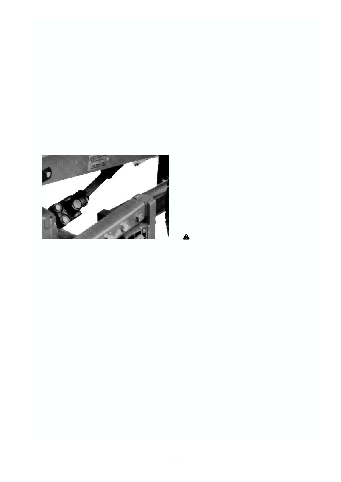
1. Remove the hair pin, pivot the seat platform
forward and locate the seat support rod in the
detent notch.
2. Depress and hold the pins located in the center of
the two (2) check valve assemblies in the top of
the transmission (Fig. 11) while pushing or
towing the machine.
Figure 11
1. Transmission check valve by-pass pins (2)
3. Start the engine momentarily after completing
repairs and make sure the pins are in the full,
disengaged (fully up) position.
Running the machine with the by-
pass valve open will overheat the transmission.
Important
Important
22
This machine produces sound levels in excess of
85dBA at the operator’s ear and can cause hearing
loss through extended periods of exposure. Wear
hearing protection when operating this machine.
CAUTION
1
Page 23

23
Maintenance
Service Interval Maintenance Procedure
After the first 10 hours • Check the power take-off belt tension.
• Check the fan and alternator belt tension.
• Change the transmission filter.
• Torque the wheel lug nuts.
After first 50 hours • Change the engine oil filter.
• Torque the engine head and check engine RPM.
Every 50 hours • Check the battery electrolyte level.
• Check the battery cable connections.
• Lubricate all grease fittings.
• Lubricate the brake cables.
• Check the cutting unit gear box oil level.
• Clean under the cutting unit belt covers.
• Check the cutting unit drive belt adjustment.
• Change the engine oil.
• Inspect the air filter and baffle
Every 100 hours • Change the engine oil filter.
• Check the electric clutch gap adjustment
• Check the power take off belt tension.
• Check the fan and alternator belt tension.
• Inspect the cooling system hoses.
Every 200 hours • Check rear wheel toe-in and steering linkage.
• Change the transmission filter.
• Torque the wheel lug nuts.
Every 400 hours • Service the air filter
• Drain and clean the fuel tank.
• Change the cutting unit’s gear box oil
• Change the fuel/water separator filter.
• Pack the rear wheel bearings.
• Coat the transmission bypass pins with grease
• Torque the head, adjust the valves and heck engine RPM.
Every 1000 hours or 2 • Replace moving hoses.
years, whichever • Replace safety switches.
occurs first • Flush and replace the coolant system fluid.
• Replace the hydraulic oil.
Maintenance
Note: Determine the left and right sides of the machine from the normal operating position.
Recommended Maintenance Schedule
Page 24

24
CHECK/SERVICE (DAILY)
1. Oil levels (Engine/Trans)
2. Coolant level
3. Tire pressure
4. Belts (Fan and power take off)
5. Fuel—Diesel only
6. Battery
7. Grease, lube points
8. Radiator screen
9. Air filter
10. Electrical clutch gap .017-.030
11.PTO Belt tension
12. Water separator
13. Fuel filter
Service Interval Charts
Fluid Specifications/Change Intervals
2 years
Type>0° C Type<0° C Capacity Change Intervals
Engine oil
Transmission
oil
Fuel
Coolant
SAE 30 CD SAE 10W-30 CD 50 hours filter 100 hours
filter 200 hours
filter 400 hours
*
Type F or FA
transmission
fluid
No. 1-D
50/50 mix Ethylene glycol anti-
freeze/water
No. 2-D
SAE 10W-30 SF, CC,
CD
7.6 l
32.2 l
5.7 l
3.7 l with filter
Filters Part No.
A. Air 98-9763
B. Fuel 98-7612
C. Fuel 98-9764
D. Transmission oil 23-2300
E. Engine oil 99-8384
Page 25

Daily Maintenance Checklist
✓ Check safety interlock operation.
✓ Check that the grass deflector is in the down
position.
✓ Check brake operation.
✓ Check fuel level
✓ Check the engine oil level.
✓ Check the cooling system fluid level.
✓ Drain and drain the water/fuel separator.
✓ Check the air cleaner restriction indicator
3
.
✓ Check the radiator and screen for debris.
✓ Check unusual engine noises.
1
✓ Check unusual operating noises
✓ Check the transmission oil level.
✓ Check the hydraulic hoses for damage.
✓ Check for fluid leaks.
✓ Check the tire pressure.
✓ Check instrument operation.
✓ Check blade condition.
✓ Lubricate all grease fittings.
2
✓ Touch up damaged paint.
1
Check the glow plug and injector nozzles if hard starting,
excess smoke, or rough running is noted.
2
Immediately after every washing, regardless of the interval
listed.
3
If indicator shows red
Lubrication
Greasing Bearings And Bushings
The traction unit has grease fittings that must be
lubricated regularly with No. 2 General Purpose
Lithium Base Grease. If the machine is operated under
normal conditions, lubricate all bearings and bushings
after every 50 hours of operation. Bearings and
bushings must be lubricated daily when operating
conditions are extremely dusty and dirty. Dusty and
dirty operating conditions could cause dirt to get into
the bearings and bushings, resulting in accelerated
wear. Lubricate grease fitting immediately after every
washing, regardless of interval specified.
Apply a liberal coating of grease to the check valve
pins once each year (Fig. 11). Also grease the bearings
in the rear axle every 500 hours, or yearly, whichever
comes first (not shown). The traction unit has bearings
and bushings that must be lubricated, and these
lubrication points are: power take-off universal shaft
(Fig. 12); lift arm pivot bushings (Fig. 13), brake pivot
bushings (Fig. 14); rear wheel spindle bushings (Fig.
15); steering plate bushings (Fig. 16); axle pin
bushing (Fig. 16); power take-off tension pivot (Fig.
17) and rear power take-off bearing (Fig. 17). Also
apply grease to both brake cables at the drive wheel
and brake pedal ends (Fig. 14).
1. Wipe grease fitting clean so foreign matter
cannot be forced into the bearing or bushing.
2. Pump grease into the bearing or bushing.
3. Wipe up excess grease.
Figure 12
25
If you leave the key in the ignition switch,
someone could accidentally start the engine and
seriously injure you or other bystanders.
Remove the key from the ignition and
disconnect the wire from the spark plug before
you do any maintenance. Set the wire aside so
that it does not accidentally contact the spark
plug.
CAUTION
Page 26

Figure 13
Figure 14
Figure 15
Figure 16
Figure 17
26
Page 27

General Air Cleaner
Maintenance
1. Check air cleaner body for damage that could
possibly cause an air leak. Replace a damaged air
cleaner body.
2. Service the air cleaner filter when the air cleaner
indicator (Fig. 18) shows red or every 400 hours
(more often in extreme dusty or dirty conditions).
Do not over-service the air filter.
Figure 18
1. Air cleaner indicator
3. Be sure the cover seals around the air cleaner
body.
Servicing the Air Cleaner
1. Pull the latch outward and turn the air cleaner
cover counter-clockwise. Remove the cover from
the body (Fig. 19). Clean the inside of the air
cleaner cover.
Figure 19
1. Air cleaner latch
2. Air cleaner cover
2. Gently slide the filter (Fig. 20) out of the air
cleaner body to reduce the amount of dust
dislodged. Avoid knocking the filter against the
air cleaner body.
Figure 20
1. Filter
3. Inspect the filter and discard it if it is damaged.
Do not wash or reuse a damaged filter.
Cleaning the Air Filter
A. Blow compressed air from inside to the
outside of dry filter element. Do not exceed
689 kPa (100 psi) to prevent damage to the
element.
B. Keep the air hose nozzle at least 2” from the
filter and move the nozzle up and down
while rotating the filter element. Inspect for
holes and tears by looking through the filter
toward a bright light.
4. Inspect the new filter for shipping damage.
Check the sealing end of the filter. Do not install
a damaged filter.
5. Insert the new filter into the air cleaner body.
Make sure the filter is sealed properly by
applying pressure to the outer rim of filter when
installing. Do not press on the flexible center of
the filter.
6. Reinstall the cover and secure the latch. Make
sure the cover is positioned with the TOP side up.
7. Reset the indicator (Fig. 18) if it is showing red.
27
1
1
1
2
Page 28

Cleaning the Radiator and
Screen
To prevent the engine from overheating, the screen
and radiator must be kept clean. Normally, check the
screen and radiator daily and clean any debris off
these parts. However, it will be necessary to check and
clean the screen and radiator more often in extremely
dusty and dirty conditions.
Note: If the engine shuts off due to overheating, first
check the radiator and screen for excessive build-up of
debris.
To thoroughly clean the radiator:
1. Remove the screen.
2. Working from the fan side of the radiator, either
spray the radiator with a water hose or blow with
compressed air.
3. After the radiator is thoroughly cleaned, clean
out debris that may have collected in the channel
at the radiator base.
4. Clean and install the screen.
Changing the Engine Oil and
Filter
Check the oil level after each day’s operation or each
time you use the machine. Change oil after every 50
hours of operation; change the oil filter after first 50
hours and every 100 hours operation thereafter. If
possible, run the engine just before changing the oil
because warm oil flows better and carries more
contaminants.
1. Position the machine on a level surface.
2. Open the hood. Set a drain pan under the oil pan,
in line with the drain plug (Fig. 21).
3. Clean the area around the drain plug.
Figure 21
1. Drain plug
4. Remove the oil drain plug and let oil to flow into
drain pan.
5. Remove and replace the oil filter (Fig. 22).
Figure 22
1. Oil filter
6. After the oil has drained, reinstall the drain plug
and wipe up any oil that spilled.
7. Fill the crankcase with oil; refer to Check the
Engine Oil.
Servicing the Fuel System
Note: Refer to Fill the Fuel Tank with Diesel Fuel for
proper fuel recommendations.
Fuel Tank
Drain and clean the fuel tank after every 800 hours
operation or yearly, whichever comes first. Also, drain
and clean the tank if the fuel system becomes
contaminated or if the machine will be stored for an
extended period. Use clean diesel fuel to flush out the
tank.
28
1
1
Page 29

Fuel Lines and Connections
Check the lines and connections every 400 hours or
yearly, whichever comes first. Inspect for
deterioration, damage or loose connections.
Water Separator
Drain water or other contaminants from the water
separator (Fig. 23) daily.
1. Place a clean container under the fuel filter.
2. Loosen the drain plug on the bottom of filter
canister. Tighten the plug after draining.
Figure 23
1. Water separator
2. Drain plug
Replace the filter canister after every 400 hours of
operation.
1. Clean the area where the filter canister mounts.
2. Remove the filter canister and clean the
mounting surface.
3. Lubricate the gasket on the filter canister with
clean oil.
4. Install the filter canister by hand until the gasket
contacts the mounting surface, then turn it an
additional
1
⁄2 turn.
Replacing the Fuel Pre Filter
Replace the fuel pre filter (Fig. 24), located between
the fuel tank and the fuel pump, after every 400
operating hours or yearly, whichever occurs first.
1. Clamp both fuel lines that connect to the fuel
filter so fuel cannot drain when you remove the
lines (Fig. 24).
2. Loosen the hose clamps at both ends of the filter
and pull the fuel lines off the filter.
Figure 24
1. Fuel pre filter
3. Slide the hose clamps onto the ends of the fuel
lines. Push the fuel lines onto the fuel filter and
secure them with hose clamps. Be sure the arrow
on the side of the filter points toward the
29
Under certain conditions, diesel fuel and fuel
vapors are highly flammable and explosive. A
fire or explosion from fuel can burn you and
others and can cause property damage.
• Use a funnel and fill the fuel tank
outdoors, in an open area, when the engine
is off and is cold. Wipe up any fuel that
spills.
• Do not fill the fuel tank completely full.
Add fuel to the fuel tank until the level is 1
in. (25 mm) below the bottom of the filler
neck. This empty space in the tank allows
the fuel to expand.
• Never smoke when handling fuel, and stay
away from an open flame or where fuel
fumes may be ignited by a spark.
• Store fuel in a clean, safety-approved
container and keep the cap in place.
DANGER
1
2
Page 30

injection pump.
Bleeding Air from Injectors
Note: This procedure should be used only if the fuel
system has been purged of air through normal priming
procedures and the engine will not start; refer to
Bleeding the Fuel System.
1. Loosen the pipe connection to the No. 1 injector
nozzle and holder assembly at injection pump.
Figure 25
1. No. 1 injector nozzle
2. Move the throttle to the FAST position.
3. Turn the key in the key switch to START and
watch the fuel flow around the connector. Turn
the key to OFF when you see a solid fuel flow.
4. Tighten the pipe connector securely.
5. Repeat these steps on the remaining nozzles.
Alternator Belt
1. Condition and Tension—Check the condition and
tension of the belts (Fig. 26) after every 100
operating hours.
A. Proper tension will allow
3
⁄8 in. (10 mm)
deflection when a force of 10 lbs. is applied
on the belt midway between the pulleys.
B. If deflection is not
3
⁄8 in. (10 mm), loosen the
alternator mounting bolts. Increase or
decrease alternator belt tension and tighten
the bolts. Check belt deflection again to
assure tension is correct.
Figure 26
1. Alternator
2. Mounting bolt
Adjusting the Throttle
1. Adjust the throttle cable (Fig. 27) so the governor
lever on the engine contacts the low- and highspeed set bolts before the throttle lever contacts
the slot in the control panel.
Figure 27
1. Throttle cable
Power Take-Off Belt
To Check Tension:
1. Turn the engine off and remove the ignition key.
Set the parking brake. Raise the engine hood and
allow the engine to cool.
2. Loosen the tensioning rod jam nut (Fig. 28).
30
1
2
1
1
Page 31

Figure 28
1. Tensioning spring
2. Tensioning rod jam nut
3. Tension adjusting bolt
3. Use a 1⁄2” wrench to tighten or loosen the belt-
tensioning spring (Fig. 28). Adjust the spring to a
length of 1-
1
⁄
2” (38 mm).
4. Tighten the jam nut.
To Replace the Belt:
1. Turn off the engine and remove the ignition key.
Set the parking brake. Raise the hood and let the
engine cool.
2. Loosen the tensioning rod jam nut (Fig. 28).
3. Using a
1
⁄2” wrench, loosen the belt tensioning
spring (Fig. 28) completely.
4. Turn power take-off pulley toward the engine and
remove the belt (Fig. 29).
5. Install the new power take-off belt and re-tension
the pulley spring to 1-
1
⁄2” (38 mm) (Fig. 28).
6. Tighten the jam nut (Fig. 28) and close the hood.
Power Take-Off Clutch
Adjustment
The power take-off electric clutch can be adjusted by
following the following procedure:
1. Turn the engine off and remove the ignition key.
Set the parking brake. Raise the engine hood and
let the engine cool.
2. Remove the left-hand bracket nut and bolt so that
you can remove the retainer bracket’s rubber
bumper (Fig. 29).
Figure 29
1. Clutch
2. .015” air gap
3. Adjusting nut (3)
4. Left retainer bracket nut & bolt
5. Electrical connector
6. Power take-off belt
3. Unplug the clutch’s electric connector (Fig. 29).
4. Adjust the air gap so that a 0.015-inch feeler
gauge slides between the clutch lining and
friction plate with light pressure (Fig. 29). The
gap can be decreased by turning the adjusting nut
clockwise.
5. Rotate the clutch by hand and adjust all three air
gaps. After all three gaps have been set, check all
three again. Adjusting one gap can alter the other
gaps.
6. Reinstall the bracket and retaining nut and bolt.
Reconnect the clutch’s electrical connector.
Adjusting the Transmission for
Neutral
The machine must not creep when you release the
traction pedal. If it does, an adjustment is required.
1. Park the machine on a level surface and shut the
31
2
4
5
2
6
1
1
3
3
38 mm
Page 32

engine off. Depress only the right brake pedal
and engage the parking brake.
2. Jack up the left front side of the machine until the
tire is off the shop floor. Support the machine
with jack stands to prevent it from falling
accidentally.
3. Lift the seat. Visually inspect the traction linkage
for a possible binding condition. Correct it, if
necessary, and check machine operation. If the
condition still exists, repeat steps 1 and 2 and go
to step 4.
4. Loosen the two locknuts securing the pump plate
so the plate can move freely (Fig. 30).
5. Start the engine and rotate pump plate (Fig. 30)
in either direction until the wheel ceases rotation.
Figure 30
1. Pump plate
2. Locknut
6. Stop the engine and tighten the locknuts to secure
the pump plate (Fig. 30).
7. Start the engine and check adjustment. Repeat
the adjustment, if necessary.
8. Stop the engine and release the right brake.
Remove the jack stands and lower the machine to
the shop floor. Test drive the machine to be sure
it doesn’t creep.
Adjusting the Parking Brake
Interlock Switch
1. Turn the engine off and remove the ignition key.
Do not engage the parking brake.
2. Remove the (6) screws securing the front steering
tower cover to frame and remove the cover
(Fig. 31).
Figure 31
1. Front steering tower cover
2. Parking brake lever/rod
3. Disconnect the switch pigtail connector from the
wire harness (Fig. 32).
4. Connect a continuity tester or ohmmeter to the
switch harness connector.
Figure 32
1. Parking brake interlock switch
2. Parking brake rod collar
3. Wire harness connector
5. Loosen the set screw securing the collar to the
parking brake rod (Fig. 32).
6. Slowly move the collar on the rod until it is
aligned with cross hairs on the switch label
(Fig. 32). Tighten the collar set screw.
7. With the parking brake disengaged, the switch
circuit should have continuity. If there is no
continuity, move the collar slightly up the rod
until there is continuity and tighten the collar set
32
2
1
1
2
3
2
1
Page 33

screw.
8. Check adjustment as follows:
Engage the parking brake. Depress the traction
pedal while the engine is running and the power
take-off lever is disengaged. The engine should
stop within 2 seconds. If the engine stops, the
switch is operating correctly; you may continue
operation. If the engine does not stop, there is a
malfunction in the interlock system.
9. Connect the switch and install the steering tower
cover.
Changing the Hydraulic Oil and
Filter
Initially, replace the hydraulic system oil and filter
after the first full day’s operation—NOT TO
EXCEED 10 HOURS. Replace the oil and filter every
250 hours thereafter. The hydraulic system is designed
to operate on any high-quality detergent oil having the
American Petroleum Institute— API—“service
classification”
SF/CC or CD. Oil viscosity—weight—must be
selected according to anticipated ambient temperature
for the season in which product will be used.
Temperature/viscosity recommendations are:
Expected Ambient
Temperature
(Extreme) over 32° C SAE 30, Type SF/CC or CD
engine oil
(Normal) 4–37° C SAE 10W-30 or 10W-40,
Type SF/CC or CD engine oil
(Cool) –1 to 10° C SAE 5W-30, Type SF/CC or
CD engine oil
(Winter) Below –1° C Type “F” or “FA” ATF
Automatic Transmission Fluid
Note: Do not mix engine oil and automatic
transmission fluid or hydraulic component damage
may result. When changing fluids, also change
transmission filter. DO NOT USE DEXRON II ATF.
Note: Fluid to operate the power steering is supplied
by the hydraulic system transmission charge pump.
Cold weather start-up may result in “stiff” operation
of the steering until the hydraulic system has warmed
up. Using proper weight hydraulic oil in the system
will minimize this condition.
The transmission and axle housing are shipped from
the factory with approximately 5 quarts (4.7 l) of SAE
10W-30 engine oil. However, check the level of
transmission oil before first starting the engine, and
daily thereafter.
1. Lower the cutting unit to the shop floor, set the
parking brake, and turn the engine OFF. Block
the two rear wheels.
2. Jack up both sides of the front axle and support it
with jack stands.
3. Clean the area around the hydraulic oil filter and
remove the filter (Fig. 33).
Figure 33
1. Filter
2. Return line
3. Suction line
4. Remove the tube that connects the axle housing
to the transmission and let the oil to flow into a
drain pan.
5. Install the new hydraulic oil filter and connect
the tube between the axle housing and
transmission. Fill the axle (reservoir)(approx. 5
qt.); refer to Check Hydraulic System Fluid.
Remove the jack stands.
6. Start the engine, cycle the steering and lift
cylinders, and check for oil leaks. Let the engine
run for about five minutes. Then shut the engine
Recommended
Viscosity and Type
33
2
1
3
Page 34

off.
7. After two minutes, check the transmission fluid
level; refer to Check Hydraulic System Fluid.
Adjusting the Service Brakes
Adjust the service brakes when there is more than one
inch (25 mm) of “free travel” of the brake pedals, or
when the brakes don’t work effectively. Free travel is
the distance the brake pedal moves before you feel
braking resistance.
Check brake adjustment after the first 25 hours of
operation. After that, they should only need adjusting
after considerable use. These periodic adjustments can
be performed where the brake cable connects to the
bottom of the brake pedals. When the cable is no
longer adjustable, the star nut on inside of the brake
drum must be adjusted to move the brake shoes
outward. However, the brake cables must be adjusted
again to compensate for this adjustment.
1. Disengage the lock arm from the right brake
pedal so both pedals work independently.
2. To reduce free travel of the brake pedals, loosen
the front nut on the threaded end of the brake
cable (Fig. 34). Then tighten the rear nut to move
the cable backward, until the brake pedals have
13 mm to 25 mm of free travel. Tighten the front
nut after the brakes are correctly adjusted.
Figure 34
1. Brake cable jam nuts
Servicing the Battery
Before welding on the machine,
disconnect the ground cable from the battery to
prevent damage to the electrical system
.
Note: Check battery condition weekly or after every
50 hours of operation. Keep the terminals and the
entire battery case clean because a dirty battery will
slowly discharge. To clean the battery, wash the entire
case with a solution of baking soda and water. Rinse
with clear water. Coat the battery posts and cable
connector with Grafo 112X (Skin-over) grease, Toro
Part No. 505-47 or petroleum jelly to prevent
corrosion.
Wiring Harness Service
Prevent corrosion of wiring terminals by applying
Grafo 112X (Skin-over) grease, Toro Part No. 505-47,
to the inside of all harness connectors whenever the
harness is replaced.
Whenever working with the electrical system, always
disconnect battery cables, negative (–) cable first, to
prevent possible wiring damage from short-outs.
Fuses
Fuses are accessible under the seat plate (Fig. 35).
Figure 35
1. Fuse block
Important
34
1
1
1
Page 35

Storage
Traction Unit
1. Thoroughly clean the traction unit, cutting unit
and the engine, paying special attention to these
areas:
• Radiator and radiator screen
• Underneath the cutting unit
• Under the cutting unit belt covers
• Counterbalance springs
• Power take-off shaft assembly
• All grease fittings and pivot points
• Remove control panel and clean the inside
of the control box
• Beneath the seat plate and the top of
transmission
2. Check the tire pressure. Inflate all traction unit
tires to 138 kPa.
3. Remove, sharpen and balance the cutting unit’s
blades. Reinstall the blades and torque the blade
fasteners to 85-110 ft-lb (115-149 N m).
4. Check all fasteners for looseness; tighten as
necessary.
5. Grease or oil all grease fittings, pivot points, and
transmission by-pass valve pins. Wipe off any
excess lubricant.
6. Lightly sand and use touch up the paint on where
paint is scratched, chipped or rusted. Repair any
dents in the metal body.
7. Service the battery and cables as follows:
A. Remove the battery terminals from the
battery posts.
B. Clean the battery, terminals and posts with a
wire brush and baking soda solution.
C. Coat the cable terminals and battery posts
with Grafo 112X skin-over grease (Toro Part
No. 505-47), or petroleum jelly to prevent
corrosion.
D. Slowly recharge the battery for 24 hours
every 60 days to prevent lead sulfation of
the battery.
Engine
1. Drain the engine oil from the oil pan and replace
the drain plug.
2. Remove and discard the oil filter. Install a new
filter.
3. Refill the engine with 4 quarts (3.8 l) of
recommended motor oil. Refer to Changing the
Engine Oil.
4. Start the engine and run it at idle speed for two
minutes.
5. Drain diesel fuel from the fuel tank, fuel lines,
pump, filter and separator. Flush the fuel tank
with clean diesel fuel and connect all fuel lines.
6. Thoroughly clean and service the air cleaner
assembly.
7. Seal the air cleaner inlet and the exhaust outlet
with weather-proof masking tape.
8. Check the oil filler cap and fuel tank cap to
ensure they are securely in place.
35
Page 36

 Loading...