

Page 1
FORM NO. 3318-239 GB Rev. B
© The Toro Company—1996
®
MODEL NO. 30233TE—60001 & UP
MODEL NO. 30243TE—6
0001 & UP
GROUNDSMASTER
2-Wheel and 4-Wheel Drive Traction Units
OPERATOR’S
MANUAL
®
223D
Page 2

To assure maximum safety, optimum performance,
and to gain knowledge of the product, it is essential
that you or any other operator of the mower read and
understand the contents of this manual before the
engine is ever started. Pay particular attention to the
SAFETY INSTRUCTIONS highlighted by this symbol:
The safety alert symbol means CAUTION, WARNING or DANGER—personal safety instruction.
Failure to comply with the instruction may result in
personal injury.
FOREWORD
The GROUNDSMASTER 223-D was developed to
satisfy the demand for a maneuverable, intermediate
size, turf maintenance rotary mower. The machine
has advanced concepts in engineering, design and
safety; and if maintained properly, it will give excellent service.
Since the GROUNDSMASTER 223-D is a high
quality product, Toro is concerned about the future
use of the machine and the safety of the user. Read
this manual to familiarize yourself with the proper
set up, operation, and maintenance instructions.
Certain information in this manual is emphasized.
DANGER, WARNING and CAUTION identify personal safety related information. IMPORTANT identifies mechanical information demanding special
attention. Be sure to read the directive because it
deals with the possibility of damaging a part or parts
of the machine. NOTE identifies general information
worthy of special attention.
If help concerning set up, operation, maintenance or
safety is ever needed, contact a local Authorized
Toro Distributor. In addition to genuine Toro replacement parts, the distributor also has optional equipment form the complete line of Toro turf care equipment. Keep your Toro all Toro – buy genuine Toro
replacement parts and accessories.
Whenever you have questions or need service, contact your local authorized Toro Distributor. In addition to having a complete line of accessories and
professional turf care service technicians, the distributor has a complete line of genuine TORO replacement parts to keep your machine operating properly.
Keep your TORO all TORO. Buy genuine TORO
parts and accessories.
TABLE OF CONTENTS
SAFETY INSTRUCTIONS 3
SPECIFICATIONS 9
BEFORE OPERATING 11
CONTROLS 15
OPERATING INSTRUCTIONS 17
LUBRICATION 20
QUICK REFERENCE AID 22
PREPARATION FOR SEASONAL STORAGE 23
PRODUCT IDENTIFICATION 23
2
Page 3

3
Safety
Training
1. Read the instructions carefully. Be familiar
with the controls and the proper use of the
equipment.
2. Never allow children or people unfamiliar with
these instructions to use the lawnmower. Local
regulations may restrict the age of the operator.
3. Never mow while people, especially children, or
pets are nearby.
4. Keep in mind that the operator or user is
responsible for accidents or hazards occurring
to other people or their property.
5. Do not carry passengers.
6. All drivers should seek and obtain professional
and practical instruction. Such instruction
should emphasize:
• the need for care and concentration when
working with rideon machines;
• control of a ride on machine sliding on a
slope will not be regained by the application
of the brake. The main reasons for loss of
control are:
– insufficient wheel grip;
– being driven too fast;
– inadequate braking;
– the type of machine is unsuitable for its
task;
– lack of awareness of the effects of ground
conditions, especially slopes;
Preparation
1. While mowing, always wear substantial
footwear and long trousers. Do not operate the
equipment when barefoot or wearing open sandals.
2. Thoroughly inspect the area where the equip-
ment is to be used and remove all objects which
may be thrown by the machine.
3. WARNING—Petrol is highly flammable.
• Store fuel in containers specifically designed
for this purpose.
• Refuel outdoors only and do not smoke
while refueling.
• Add fuel before starting the engine. Never
remove the cap of the fuel tank or add petrol
while the engine is running or when the
engine is hot.
• If petrol is spilled, do not attempt to start the
engine but move the machine away from the
area of spillage and avoid creating any
source of ignition until petrol vapors have
dissipated.
• Replace all fuel tanks and container caps
securely.
4. Replace faulty silencers.
5. Before using, always visually inspect to see that
the blades, blade bolts and cutter assembly are
not worn or damaged. Replace worn or damaged blades and bolts in sets to preserve balance.
6. On multi-bladed machines, take care as rotating
one blade can cause other blades to rotate.
Operation
1. Do not operate the engine in a confined space
where dangerous carbon monoxide fumes can
collect.
2. Mow only in daylight or in good artificial light.
3. Before attempting to start the engine, disengage
all blade attachment clutches and shift into neutral.
4. Do not use on slopes of more than:
• Never mow side hills over 5°
• Never mow uphill over 10°
• Never mow downhill over 15°
5. Remember there is no such thing as a “safe”
slope. Travel on grass9 slopes requires particu-
Page 4

Safety
4
lar care. To guard against overturning:
• do not stop or start suddenly when going up
or downhill;
• engage clutch slowly, always keep machine
in gear, especially when travailing downhill;
• machine speeds should be kept low on
slopes and during tight turns;
• stay alert for bumps and hollows and other
hidden hazards;
• never mow across the face of the slope,
unless the lawnmower is designed for this
purpose.
6. Use care when pulling loads or using heavy
equipment.
• Use only approved drawbar hitch points.
• Limit loads to those you can safely control.
• Do not turn sharply. Use care when reversing.
• Use counterweight(s) or wheel weights when
suggested in the instruction handbook .
7. Watch out for traffic when crossing or near
roadways.
8. Stop the blades rotating before crossing surfaces
other than grass.
9. When using any attachments, never direct dis-
charge of material toward bystanders nor allow
anyone near the machine while in operation .
10. Never operate the lawnmower with defective
guards, shields or without safety protective
devices in place.
11. Do not change the engine governor settings or
overspeed the engine. Operating the engine at
excessive speeds may increase the hazard of
personal injury.
12. Before leaving the operator's position:
• disengage the power take-off and lower the
attachments;
• change into neutral and set the parking
brake;
• stop the engine and remove the key.
13. Disengage drive to attachments, stop the engine,
and disconnect the spark plug wire(s)or remove
the ignition key
• before cleaning blockages or unclogging
chute;
• before checking, cleaning or working on the
lawnmower;
• after striking a foreign object. Inspect the
lawnmower for damage and make repairs
before restarting and operating the equipment;
• if the machine starts to vibrate abnormally
(check immediately).
14. Disengage drive to attachments when transport-
ing or not in use.
15. Stop the engine and disengage drive to attach-
ment
• before refueling;
• before removing the grass catcher;
• before making height adjustment unless
adjustment can be made from the operator's
position.
16. Reduce the throttle setting during engine runout
and, if the engine is provided with a shutoff
valve, turn the fuel off at the conclusion of
mowing.
Maintenance and Storage
1. Keep all nuts, bolts and screws tight to be sure
the equipment is in safe working condition.
2. Never store the equipment with petrol in the
tank inside a building where fumes may reach
an open flame or spark.
3. Allow the engine to cool before storing in any
enclosure.
4. To reduce the fire hazard, keep the engine,
silencer, battery compartment and petrol storage
area free of grass, leaves, or excessive grease.
5. Check the grass catcher frequently for wear or
Page 5

5
Safety
deterioration.
6. Replace worn or damaged parts for safety.
7. If the fuel tank has to be drained, this should be
done outdoors
8. On multi-bladed machines, take care as rotating
one blade can cause other blades to rotate.
9. When machine is to be parked, stored or left
unattended, lower the cutting means unless a
positive mechanical lock is used.
Sound & Vibration Levels
Sound Levels
This unit has an equivalent continuous A-weighted
sound pressure at the operator ear of: 80 dB(A),
based on measurements of identical machines per
84/538/EEC.
This unit has a sound power level of 104
dB(A)/1pW, based on measurements of identical
machines per procedures outlined in Directive
84/538/EEC and amendments
Vibration Levels
This unit has a vibration level of 5.0 m/s2at the
hands, based on measurements of identical machines
per ISO 5349 procedures.
This unit does not exceed a vibration level of 0.5
m/s
2
at the posterior based on measurements of iden-
tical machines per ISO 2631 procedures.
Page 6
6
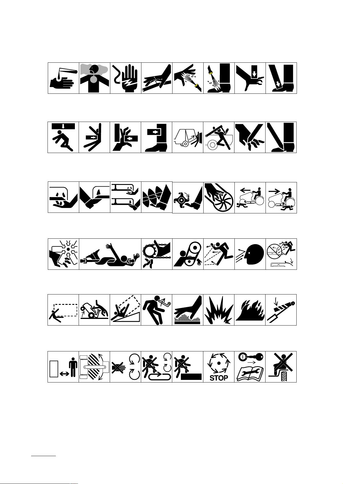
Symbol Glossary
Caustic liquids,
chemical burns to
fingers or hand
Poisonous
fumes or toxic
gases, asphyxiation
Electrical shock,
electrocution
High pressure
fluid, injection
into body
High pressure
spray, erosion of
flesh
High pressure
spray, erosion of
flesh
Crushing of
fingers
or hand,
force
applied from
above
Crushing of
toes or foot, force
applied from above
Crushing of
whole body,
applied from
above
Crushing of
torso, force
applied from side
Crushing of fingers
or hand/, force
applied from side
Crushing of
whole body
Crushing of
head, torso and
arms
Cutting of
fingers or hand
Cutting of footCrushing of leg,
force applied
from side
Severing of
fingers or hand,
mower blade
Severing of
toes or foot,
mower blade
Severing of
toes or fingers,
rotary mower
blade
Cutting or
entanglement of
foot, rotating auger
Severing of
foot, rotating
knives
Severing of
fingers or hand,
impeller blade
Dismemberment, front engine
mower in forward
motion
Dismemberment, front engine
mower in rearward
motion
Severing of
fingers or hand,
engine fan
Whole body entanglement,
implement input drive line
Fingers or
hand entanglement, chain
drive
Hand & arm
entanglement,
belt drive
Thrown or flying
objects, whole
body exposure
Thrown or
flying objects,
face exposure
Thrown or flying
objects, rotary
mover
Runover/backover, vehicle
Machine
tipping, riding
mower
Machine rollover,
ROPS (rear
engine mower)
Stored energy
hazard, kickback
or upward motion
Hot surfaces,
burns to fingers
or hands
Explosion Fire or open
flame
Secure lifting
cylinder with locking
device before getting
in hazardous area
Do not step on
loading platform
if PTO is connected to tractor &
engine is running
Do not step Wait until all
machine components have
completely
stopped before
touching them
Shut off engine
& remove key
before performing maintenance
or repair work
Stay a safe
distance from
the machine
Stay clear of
articulation area
while engine is
running
Do not open
or remove safety
shields while
engine is
running
Riding on this
machine is allowed
only on a passenger seat & only if the
driver’s view is not
hindered
Page 7

7
Safety
Consult technical
manual for proper
service
procedures
Head protection
must be worn
Brake system
Filter Temperature Failure/
Fasten seat
belts
Hearing
protection must
be worn
Oil Coolant (water) Intake air Exhaust gas Pressure Level indicator Liquid level
Caution, toxic
risk
Malfunction
Safety alert
triangle
Start switch/
mechanism
Outline safety
alert symbol
Flush with water Engine Transmission Hydraulic systemFirst aid
On/start Off/stop Engage
Read operator’s
manual
Fire, open light
and smoking
prohibited
Eye protection
must be worn
Disengage
Plus/increase/
positive polarity
Volume empty Volume full Machine travel
Oil lubrication
point
Engine lubricating
oil temperature
Minus/decrease/
negative polarity
Lift point Jack or
Engine coolant
Horn
direction,
forward/
rearward
support point
Engine coolant
pressure
Battery charging
condition
Control lever
operating
direction, dual
direction
Draining/
emptying
Engine coolant
filter
Hourmeter/
elapsed operating
hours
Control lever
operating
direction, multiple
direction
Engine lubricating oil
Engine coolant
temperature
Fast Slow Continuous
Clockwise
rotation
Engine
lubricating
oil pressure
Engine intake/
combustion air
Counter-clockwise rot ation
Engine lubricating
oil level
Engine intake/combustion air pressure
variable, linear
Grease
lubrication
point
Engine lubricating
oil filter
Engine intake/air
filter
Page 8

Safety
8
Engine start Engine stop Engine failure/
malfunction
Engine rotational
speed/frequency
Choke Primer (start aid) Electrical preheat
(low temperature
start aid)
n/min
Transmission
oil
Transmission
oil pressure
Transmission
oil temperature
Transmission
failure/malfunction
Clutch Neutral High Low Forward
NHLF
Reverse
Park First gear
Second gear
Third gear (other #'s
may be used until the
maximum # of forward
gears is reached.)
Hydraulic oil
Hydraulic oil
pressure
Hydraulic oil
level
RP 2 31
Hydraulic oil
filter
Hydraulic oil
temperature
Hydraulic oil
failure/malfunction
Fuel level
Parking brake Fuel
Fuel filter Fuel system
failure/malfunction
Lock Unlock Differential lock 4-Wheel drive Power Take-OffDiesel fuel Unleaded fuel Headlights
Cutting unit,
lower
Cutting unit,
hold
Cutting unit,
float
Cutting unit Cutting unit,
raise
Power Take-Off,
rotational speed
Blade cutting
element
Blade cutting
element, height
adjustment
Cutting unit,
transport
position
Cutting unit,
raise to transport
position
Cutting unit,
lower to transport
position
Attachment
lower
Attachment
raise
Spacing distance Snow thrower,
collector auger
Traction
Above working
temperature
range
Drilling Manual metal
arc welding
Manual Water pump Keep dry Weight Do not dispose
in the garbage
CE logo
Page 9

Engine:
Manufacturer—Mitsubishi.
Horsepower—22 (16 Kw) @ 3000 RPM.
Torque—40 ft-lb (54.2 Nm) @ 2400 RPM.
Displacement—58.1 cu in. (952 cc).
Crankcase Capacity—3.8 qt. (3.6 L).
Governor—Mechanical.
Governor Limit—3100–3250 RPM.
Idle Speed—1700 RPM.
Air Cleaner: Donaldson heavy duty with precleaner. Remote mounted.
Fuel Tank Capacity: 8.5 gal. (32 l).
Fuel Filter/Water Separator: 3-micron spin–on
type element. Replaceable (Toro Part No. 63-8300).
Fuel Pump: 12-volt electric (transistor type)
w/replaceable fuel filter (Toro Part No. 43-2550).
Cooling System:
Radiator—6 qt (5.7 l) capacity.
Expansion Tank—Remote mounted; 1 qt (0.946 l)
capacity. System contains a 50/50 mix of ethylene
glycol anti-freeze and water.
Electrical: Battery—12 volt, BCI group size 26, 530
Amp at 0° F. 35-amp alternator with regulator/rectifier.
Drive Coupling: Transmission driven by steel shaft
with flexible rubber couplings at each end.
Transmission:
Manufacturer & Type—Sundstrand hydrostatic, Type
U15.Normal Charge Pressure – 70–150 psi
(483–1034 kPa).
Implement Relief Setting – 700–800 psi
(4 826 – 5 516 kPa).
Hydraulic Filter: 25-micron mounted directly to
transmission. Replaceable (Toro Part No. 23-2300).
Drive Axle: Manufacturer – Dana Corp., Model
GT–20. Axle serves as a hydraulic fluid reservoir
and mates directly with the transmission.
Approximately 5 qt (4.7 l) capacity. 4-Wheel Drive
has mechanical rear axle coupled to front axle by a
drive shaft and clutch.
Brakes: Mechanical drum type, 7 in. (17.8 cm) dia.
x 1-3/4 in. (45 mm) wide. Individually controlled by
two pedals connected by cable and conduit for steering assist. Pedals may be latched together for two
wheel braking. Lever provided for the parking
brake.
Tires, Wheels, Pressure:
Front Tires—23 x 8.50 - 12
Rear Tires—16 x 6.50 - 8
All tires 4 ply rating, tubeless type.
Pressure—20 psi (138 kPa).
Steering: 13 in. (33 cm) steering wheel. TRW power
steering valve.
Main Frame: Frame is welded, formed steel.
Instrumentation: Fuel gauge, water temperature
gauge, hour meter and warning lights for high temperature shutdown, oil pressure, amperage and glow
plug are mounted on the console.
Controls: Throttle, PTO switch, parking brake,
implement lift, ignition switch and glow plug switch
are all hand-operated. Forward/reverse traction pedal
and turning brakes are foot operated.
PTO Drive: PTO shaft is clutched by a torqueteamed HA Section, spring tensioned V-belt directly
from the engine output shaft. PTO shaft engaged by
electric clutch/brake assembly. PTO speed – 2200
RPM @ 3250 RPM engine speed.
Implement Connection—Universal joint and telescoping shaft assembly.
Lift Cylinders: Two, with 2 in. (51 mm) bore, 3.5
in. (89 mm) stroke.
Interlock Switches: Prevents engine starting if traction pedal or PTO switch are engaged. Stops the
engine if operator leaves seat with either traction
pedal or PTO switch engaged.
Dimensions and Weight:
Length: 208 cm (82 in.)
Width (2-Wheel drive): 111 cm (44 in.)
(4-Wheel drive): 119 cm (47 in)
Height: 127 cm (50 in.)
Weight: 418 kg (1120 lb)
9
Specifications
Page 10

CHECK THE ENGINE OIL
The engine is shipped with 3.8 qt (3.6 l) of oil in the
crankcase; however, check the oil level before and
after you first start the engine.
1. Position the machine on a level surface.
2. Open the hood.
3. Remove the dipstick and wipe it with a clean
rag. Insert the dipstick into the tube and make
sure it is seated fully. Remove the dipstick and
check the level of oil (Fig. 1). If the oil level is
low, add enough oil to raise the level to the
FULL mark on the dipstick. Do not overfill
(Fig. 2).
Figure 1
1. Engine oil dipstick
2. Engine oil filter
3. Oil drain plug
Note: If the level of oil is at the ADD mark on
the dipstick, add 1 pint (0.47 l) of oil and
recheck the level. Do not overfill.
4. The engine uses any high-quality 10W30 deter-
gent oil having the American Petroleum
Institute – API–”service classification” CD.
IMPORTANT: Check the level of oil every 5
operating hours or daily. Change oil after
every 50 hours of operation.
Figure 2
1. Engine oil fill
5. Insert the dipstick into the tube.
CHECK COOLING SYSTEM
Clean debris off screen and front of radiator daily
(Fig. 3), hourly if conditions are extremely dusty and
dirty.
Figure 3
1. Radiator
2. Radiator screen
3. Screen channel
The cooling system is filled with a 50/50 solution of
water and permanent ethylene glycol anti-freeze.
Check the level of coolant at the beginning of each
day (Fig. 4) before starting the engine. Capacity of
the cooling system is 6 quarts (5.7 l).
1. Carefully remove the radiator cap and the
10
Before Operating
Page 11

expansion tank cap.
Figure 4
1. Radiator cap
2. Expansion tank cap
3. Expansion tank fill marks
2. Check the level of coolant in the radiator. The
radiator should be filled to the top of the filler
neck and the expansion tank filled to between
the marks on its side.
3. If the coolant level is low, replenish the system.
DO NOT OVERFILL.
4. Install the radiator and expansion tank caps.
CHECK HYDRAULIC SYSTEM
FLUID
The hydraulic system was designed to operate on
any high quality detergent oil having the American
Petroleum Institute–API–“service classification” SF,
CC or CD. Oil viscosity—weight—must be selected
according to anticipated ambient temperature.
Temperature/viscosity recommendations are:
Expected Ambient Recommended Viscosity
Temperature and type
Over 32°C SAE 30, Type SF, CC or
CD
4–38° C SAE 10W-30 or 10W40
Type SF, CC or CD
–1–10° C SAE 5W30, Type SF, CC
or CD
Below –1° C Type “F” or “FA”
Automatic Transmission Fluid
Note: Do not mix engine oil and automatic transmis-
sion fluid or hydraulic component damage may
result. When changing fluids, also change transmission filter. DO NOT USE DEXRON II ATF.
The axle housing acts as the reservoir for the system.
The transmission and axle housing are shipped from
the factory with approximately 5 quarts (4.7 l) of
SAE 10W–30 engine oil. However, check the level
of transmission oil before the engine is first started
and daily thereafter.
1. Position the machine on a level surface. Place
all controls in their neutral position and start the
engine. Run the engine at lowest possible RPM
to purge the system of air. DO NOT ENGAGE
THE PTO. Turn the steering wheel several
times fully to the left and right. Raise the cutting unit to extend the lift cylinders, aiming
steering wheels straight forward and stop the
engine.
2. Remove the dipstick cap (Fig. 5) from filler
neck and wipe it with a clean cloth. Screw the
dipstick cap finger-tight onto filler neck; then
remove it and check the level of fluid. If the
level is not within 1/2 inch (13 mm) from the
groove in the dipstick (Fig. 5), add SAE
10W–30 engine oil, or, if used, automatic transmission fluid to raise the level to groove mark.
Do not overfill.
IMPORTANT: When adding transmission
fluid to the hydraulic system, use a funnel
with a fine wire screen—200 mesh or finer—
and make sure funnel and transmission fluid
are immaculately clean. This procedure prevents accidental contamination of the
hydraulic system.
11
Before Operating
If the engine has been running, pressurized hot
coolant can escape and cause burns when the
radiator cap is removed.
CAUTION
Page 12

Figure 5
1. Hydraulic system reservoir fluid/add dipstick cap
3. Thread the dipstick fill cap finger-tight onto
filler neck. It is not necessary to tighten cap
with a wrench.
4. Check all hoses and fittings for leaks.
FILL THE FUEL TANK
The engine runs on No. 2-D or 1-D automotive type
diesel fuel with a minimum cetane rating of 40.
Note; Higher cetane rated fuel may be required if
the machine is to be used at high altitude and lowatmospheric temperatures.
Use No. 2-D diesel fuel at temperatures above 20° F
(–7° C). and No. 1-D diesel fuel below 20° F (–7°
C). Use of No. 1-D diesel fuel at lower temperatures
provides lower flash point and pour point characteristics, therefore easing startability and lessening
chances of chemical separation of the fuel due to low
temperatures (wax appearance, which may plug filters).
Use of No. 2-D diesel fuel above 20° F (–7° C) will
contribute toward longer life of the pump components. Do not use furnace oil.
Store fuel outside of buildings in a convenient location. Tipping the front of the tank up slightly will
allow contaminants to collect at the lower end away
from the outlet. Never empty the tank below 4 in.
(10 cm) from the bottom of the tank to avoid picking
up water and other contaminants that may have collected at the bottom. Either filter the remainder at
the bottom through a chamois or dispose of it periodically to prevent excessive build-up of contaminants.
Keep all fuel containers free of dirt, water, scale and
other contaminants. Many engine difficulties can be
traced to contaminants in the fuel.
Use only metal containers for fuel storage. DO NOT
store the fuel in a galvanized metal container. A
chemical reaction will result, which will plug the filters and cause possible fuel system damage.
If possible, fill the fuel tank at the end of each day.
This will prevent possible buildup of condensation
inside the fuel tank, preventing possible engine damage. Allow the engine to thoroughly cool down
before refueling.
1. Using a clean cloth, clean the area around the
fuel tank cap.
2. Remove cap from the fuel tank (Fig. 6) and fill
the 8 gallon (34 l) tank to within 1 inch (25
mm) from the top with diesel fuel. Install fuel
tank cap tightly after filling tank.
Before Operating
12
Because diesel fuel is flammable, use caution
when storing or handling it. Do not fill the fuel
tank while the engine is running, hot or when
the machine is in an enclosed area. Vapors may
build up and be ignited by a spark or flame
source many feet away. DO NOT SMOKE
while filling the fuel tank to prevent the possibility of an explosion. Always fill the fuel tank
outdoors and wipe up any spilled diesel fuel
before starting the engine. Use a funnel or
spout to prevent spilling diesel fuel and fill the
tank to about 25 mm below the filler neck.
Store diesel fuel in a clean, safety-approved
container and keep the cap in place on the container. Keep diesel in a cool, well-ventilated
place; never in an enclosed area such as a hot
storage shed. To assure volatility and to prevent
contamination, do not buy more than a 6-month
supply.
DANGER
Page 13

Figure 6
1. Fuel tank cap
Four-Wheel Drive Models Only:
Check Rear Axle Lubricant
The rear axle has three separate reservoirs which use
SAE 80W-90 gear lub. Although the axle is shipped
with lubricant from the factory, check the level
before operating the machine.
1. Position the machine on a level surface.
2. Remove a check plug from each end of the axle
and make sure lubricant is up to the bottom of
the hole. If the level is low, remove one of the
mounting bolts above each end plug and add
enough lubricant to bring the level up to the
bottom of the hole (Fig. 7).
3. Remove the plug in the center of the axle and
check the level. If the level is low, add enough
lubricant to bring the level up to the bottom of
the hole.
4. To make sure that the cavities at each end of the
axle tube are filled, jack up each side of the axle
6 inches. Then with the axle level, check the
level at the center plug hole.
Figure 7
1. Check plugs (2)
2. Mounting bolts
13
Before Operating
Page 14

Service Brakes (Fig. 8 )—The left and right brake
pedals are connected to the left and right front
wheels. Since both brakes work independently of
each other, the brakes can be used to turn sharply or
to increase traction if one wheel tends to slip while
operating on certain slope conditions. However, wet
grass or soft turf could be damaged when the brakes
are used to turn sharply. To make a “quick-stop”,
depress both brake pedals together. Always lock the
brakes together when transporting the traction unit.
Figure 8
1. Parking brake knob
2. Right brake pedal
3. Left brake pedal
Parking Brake—Whenever the engine is shut off,
the parking brake must be engaged to prevent accidental movement. To engage the parking brake, push
lock arm (Fig. 9) on left brake pedal so that it locks
together with the right pedal. Next, push down fully
on both pedals and pull the parking brake knob out
(Fig. 8) then release the pedals. To release the parking brake, depress both pedals until the parking
brake knob retracts. Before starting the engine, however, the lock arm may be disengaged from the left
brake pedal so both pedals work independently with
each front wheel.
Amp Light (Fig. 10)—The amp light should be off
when the engine is running. If it is on, the charging
system should be checked and repaired if necessary.
Hour Meter (Fig. 10)—Accumulated engine operating time registers on the hour meter.
Figure 9
1. Left brake pedal
2. Right brake pedal
3. Lock arm
Temperature Gauge and High Temperature Light
(Fig. 10)—The coolant temperature gauge registers
the coolant temperature in the system. If the temperature gets too high, the engine will automatically
shut off and the High Temperature shutoff light will
light. When this happens, turn the ignition key off,
check the radiator for debris, check the fan belt and
check the expansion tank for proper coolant level.
The high temperature shutoff will automatically reset
when the coolant temperature has reached a safe
level.
Figure 10
1. Left brake pedal
2. Right brake pedal
3. Lock arm
4. High temperature shutoff light
5. Ignition key switch
6. Oil pressure light
7 PTO switch
8. Glow plug indicator
9. Glow plug switch
10. Throttle
11. Hydraulic lift lever
12. Fuel gauge
Low Oil Pressure Light (Fig. 10)—If engine oil
14
Controls
Page 15

pressure falls below a safe level, the light glows.
Stop the engine and repair before resuming operation.
PTO Switch (Fig. 10)—Pull up on the sleeve on the
toggle switch handle and move the handle to ON to
ENGAGE electric PTO clutch. Pull up on the sleeve
and move the handle to OFF to DISENGAGE electric PTO clutch. The only time the PTO switch
should be in the ENGAGE position is when the
implement is down in operating position and ready
to begin operation.
Ignition Key Switch (Fig. 10)—The ignition
switch, which is used to start and stop the engine,
has three positions: OFF, RUN and START. Turn the
key clockwise—START position—to engage the
starter motor. Release the key when the engine starts.
The key will move automatically to the ON position.
To shut the engine off, turn the key counterclockwise
to the OFF position.
Glow Plug Switch and Indicator (Fig. 10)—Use to
preheat the engine cylinders prior to cold engine
starting procedures—cylinders are preheated automatically during warm engine start operation. For
cold starting, push the switch lever upward and hold
while viewing the indicator. The indicator will glow
orange when the glow plugs are activated. Length of
time necessary to preheat cylinders should be determined by atmospheric temperature.
Throttle (Fig. 10)—The throttle is used to operate
the engine at various speeds. Moving the throttle
forward increases engine speed—FAST; rearward
decreases engine speed—SLOW. The throttle controls the speed of the cutter blades and, together with
traction pedal, controls the ground speed of the traction unit.
Hydraulic Lift Lever (Fig. 10)—The hydraulic lift
lever has three positions: FLOAT, TRANSPORT and
RAISE. To lower the cutting unit to the ground,
move the lift lever forward into the notch FLOAT.
The FLOAT position is used for mowing and when
the machine is not in operation. To raise the cutting
unit, pull the lift lever rearward to the RAISE position. After the cutting unit is raised, allow the lift
lever to move to the TRANSPORT position. The
cutting unit must be raised when driving from one
work area to another.
Traction Pedal (Fig. 11 )—The traction pedal has
two functions: one is to make the machine move forward, the other is to make it move rearward. Using
the heel and toe of the right foot, depress the top of
the pedal to move forward and the bottom of the
pedal to move rearward. Ground speed is proportionate to how far pedal is depressed. For maximum
ground speed, the traction pedal must be fully
depressed while the throttle is in the FAST position.
Maximum speed forward is 10 mph (16 Km/hour).
To get maximum power under heavy load or when
ascending a hill, have the throttle in the FAST position while depressing the traction pedal slightly to
keep engine rpm high. When engine rpm begins to
decrease, release the traction pedal slightly to allow
rpm to increase.
Figure 11
1. Traction pedal
Seat Adjusting Handle—To adjust the seat, loosen
the adjusting knobs and slide the seat to the desired
position. Tighten the knobs to lock the seat in place.
Seat Adjusting Handle—Deluxe Seat—To adjust
the seat, move the lever on left side outward, slide
the seat to the desired position and release the lever
so it will lock in track.
15
Controls
Never raise the cutting unit while blades are
rotating because it is hazardous.
CAUTION
Page 16

STARTING/STOPPING THE
ENGINE
IMPORTANT: The fuel system must be bled if
any of the following situations have occurred.
A. Initial start up of a new machine.
B. The engine has ceased running due to lack of
fuel.
C. Maintenance has been performed upon fuel sys-
tem components; i.e., filter replaced, separator
serviced, etc.
Refer to Bleeding The Fuel System.
1. Ensure the parking brake is set, the PTO switch
is in OFF and the lift lever is in the TRANSPORT or FLOAT position (Fig. 9). Remove
your foot from the traction pedal and make sure
it is in neutral.
2. Move the throttle control (Fig. 9) to the full
FAST position.
3. When temperature is below 15°C (60° F), push
glow plug switch to ON (Fig. 9) and hold for
the suggested interval.
Note: Do not exceed 1 minute of continuous
use or glow plug may burn out prematurely.
Note: Refer to chart indicating approximate
preheat time suggested in various temperature
ranges.
Temperature Preheat time (sec)
Above 5° C 10
+5° C to –5° C 20
Below –5° C 30
4. Turn the key in ignition switch to START posi-
tion (Fig. ). Release the key immediately when
the engine starts and allow it to return to RUN
position. Move the throttle control to the SLOW
position.
Note: Do not run the starter motor more than
20 seconds at a time or premature starter failure
may result. If the engine fails to start after 20
seconds, turn the key to OFF, recheck the controls and procedures, wait 10 additional seconds
and repeat the starter operation.
5. When the engine is started for the first time, or
after the engine oil change or overhaul of the
engine, transmission or axle, operate the
machine in forward and reverse for one to two
minutes. Also operate the lift lever and PTO
lever to assure proper operation of all parts.
Turn the power steering wheel to the left and
right to check steering response. Then shut the
engine off and check fluid levels, check for oil
leaks, loose parts and any other noticeable malfunctions.
6. To stop the engine, move the throttle control
backward to SLOW, move the PTO switch to
OFF and turn the ignition key to OFF. Remove
the key from the switch to prevent accidental
starting.
BLEEDING THE FUEL SYSTEM
1. Raise the hood over the engine.
2. Loosen the air bleed screw on top of the fuel fil-
ter/water separator (Fig. 12).
3. Turn the ignition key switch to RUN. The elec-
tric fuel pump will begin operation, thereby
forcing air out around air bleed screw. Leave the
key in the RUN position until a solid stream of
fuel flows out around screw. Tighten the screw
and turn the key to OFF.
16
Operation
Shut the engine off and wait for all moving
parts to stop before checking for oil leaks,
loose parts or other malfunctions.
CAUTION
Page 17

Figure 12
1. Fuel filter
2. Air bleeder screw
4. Open the air bleed screw on the fuel injection
pump (Fig. 13) with a 10 mm wrench.
Figure 13
1. Fuel injection pump bleeder
5. Turn the key to the RUN position. The electric
fuel pump will begin operation, thereby forcing
air out around air bleed screw on fuel injection
pump. Leave the key in the RUN position until
solid stream of fuel flows out around the screw.
Tighten the screw and turn the key to OFF.
CHECKING THE INTERLOCK
SAFETY SYSTEM
The purpose of the safety interlock system is to prevent the engine from cranking or starting unless the
traction pedal is in neutral and the PTO switch is in
the OFF position. Also, the engine will stop when
the PTO control is engaged or the traction pedal is
depressed with the operator off the seat.
1. Move the PTO switch to OFF and remove your
foot from the traction pedal so it is fully
released.
2. Turn the key to START. The engine should
crank. If the engine cranks, go to step 3. If the
engine does not crank, there may be a malfunction in the interlock system.
3. Rise from the seat and engage the PTO switch
while the engine is running. The engine should
stop within 2 seconds. If the engine stops, the
switch is operating correctly; thus, go to step 4.
If the engine does not stop, there is a malfunction in the interlock system.
4. Rise from the seat and depress the traction
pedal while the engine is running and the PTO
lever is disengaged. The engine should stop
within 2 seconds. If the engine stops, the switch
is operating correctly; thus, continue operation.
If the engine does not stop, there is a malfunction in the interlock system.
OPERATING
CHARACTERISTICS
Practice driving the GROUNDSMASTER®223-D
before initial operation because it has a hydrostatic
transmission and its characteristics are different than
some turf maintenance machines. Some points to
consider when operating the traction unit and cutting
unit are the transmission, engine speed, load on the
cutting blades, and the importance of the brakes.
To maintain enough power for the traction unit and
cutting unit while mowing, regulate traction pedal to
keep engine rpm high and somewhat constant. A
good rule to follow is: decrease ground speed as the
load on the cutting blades increases; and increase
17
Operation
Do not disconnect the safety switches because
they are for the operator’s protection. Check
operation of the switches daily to be sure the
interlock system is operating correctly. If a
switch is malfunctioning, replace it before operating the machine. Replace the switches every
two years to be sure of maximum safety.
CAUTION
Page 18

ground speed as the load on the blades decreases.
This allows the engine, working with the transmission, to sense the proper ground speed while maintaining the high blade tip speed necessary for good
quality of cut. Therefore, let the traction pedal to
move upward as engine speed decreases, and depress
the pedal slowly as speed increases. By comparison,
when driving from one work area to another—with
no load and cutting unit raised—have the throttle in
the FAST position and depress the traction pedal
slowly but fully to attain maximum ground speed.
CAUTION: This product may exceed noise levels of
85 dB(A) at the operator position. Ear protectors are
recommended for prolonged exposure to reduce the
potential of permanent hearing damage.
Another characteristic to consider is the operation of
the brakes. The brakes can be used to assist in turning the machine; however, use them carefully, especially on soft or wet grass because the turf may be
torn accidentally. The brakes can be used to great
advantage to control the direction of the cutting unit
when trimming along fences or similar objects.
Another benefit of the brakes is to maintain traction.
For example; in some slope conditions, the uphill
wheel slips and loses traction. If this situation
occurs, depress the uphill brake pedal gradually and
intermittently until the uphill wheel stops slipping,
thereby increasing traction on the downhill wheel. If
independent braking is not desired, engage the lever
on the left brake pedal with right pedal. This provides simultaneous braking at both wheels.
Before stopping the engine, disengage all controls
and move the throttle to SLOW. Moving the throttle
to SLOW reduces high engine speed, noise and
vibration. Turn the ignition key to OFF to stop the
engine.
PUSHING OR TOWING THE
TRACTION UNIT
In an emergency, the traction unit can be pushed or
towed for a very short distance. However, Toro does
not recommend this as standard procedure.
IMPORTANT: Do not push or tow the traction
unit faster than 2 to 3 mph (3.2 to 4.8 Km/hour)
because transmission may be damaged. If the
traction unit must be moved a considerable distance, transport it on a truck or trailer. Whenever
the traction unit is pushed or towed, the by-pass
valve must be open.
1. Remove the hair pin and pivot the seat platform
forward and locate seat support rod in the detent
notch.
2. Depress and hold the pins located in the center
of the two (2) check valve assemblies in the top
of the transmission (Fig. 14) while pushing or
towing the machine.
Figure 14
1. Transmission check valve bypass pins (2)
3. Start the engine momentarily after repairs are
completed and make sure the pins are in the
fully disengaged (fully up) position.
IMPORTANT: Running the machine with by-pass
valve open will cause the transmission to overheat.
Operation
18
Adequate rear weight is necessary to prevent the
rear wheels from leaving the ground. Do not
stop suddenly while cutting unit or implement is
raised. Do not travel down hill with the cutting
unit or implement raised. If the rear wheels
leave the ground, steering is lost.
CAUTION
Page 19

LUBRICATION
GREASING BEARINGS AND BUSHINGS
The traction unit has grease fittings that must be
lubricated regularly with No. 2 General Purpose
Lithium Base Grease. If the machine is operated
under normal conditions, lubricate all bearings and
bushings after every 50 hours of operation or immediately after every washing. Bearings and bushings
must be lubricated daily when operating conditions
are extremely dusty and dirty. Dusty and dirty operating conditions could cause dirt to get into the bearings and bushings, resulting in accelerated wear.
Apply a liberal coating of grease to the check valve
pins once each year (Fig. 14). The traction unit has
bearings and bushings that must be lubricated, and
these lubrication points are shown in the following
figures.
1. Wipe grease fitting clean so foreign matter can-
not be forced into the bearing or bushing.
2. Pump grease into the bearing or bushing.
3. Wipe up excess grease.
Figure 15
Figure 16
Figure 17
Figure 18 (Four-Wheel Drive)
19
Maintenance
Page 20

Figure 19
Figure 20 (2-Wheel Drive only)
Figure 21
Figure 22 (2-Wheel Drive only)
Maintenance
20
Page 21

21
Maintenance
Quick Reference
1. Oil levels
2. Coolant level
3. Tire Pressure
4. Belts
5. Fuel—Diesel Only
6. Battery
7. Grease, Lube points
8. Radiator screen
9. Air cleaner
10. Electric clutch gap
11. PTO belt tension
12. Water separator
FiltersPart No.
Air 277110
Fuel pump 43-2550
Fuel line 63-8300
Transmission oil 23-2300
Engine oil 67-4330
Change Intervals
Fluids >0° C <0° C Capacity Fluid Filter
Engine oil SAE 30 CD SAE 10W-30 CD 3.6 l 50 hours 100 hours
Fuel No. 2-D No. 1-D 34 l -------- 400 hours
Coolant 50/50 mix Ethylene glycol antifreeze 6 l 2 years
Page 22

Traction Unit
1. Thoroughly clean the traction unit, cutting unit
and the engine, paying special attention to these
areas:
- radiator and radiator screen
- underneath the cutting unit
- under the cutting unit belt covers
- counterbalance springs
- P.T.O. Shaft Assembly
- all grease fittings and pivot points
- remove control panel and clean out the inside
of the control box
- beneath seat plate and top of transmission
2. Check the tire pressure. Inflate all traction unit
tires to 20 psi.
3. Remove, sharpen and balance the cutting unit’s
blades. Reinstall the blades and torque the blade
fasteners to 85–110 ft-lb (115–149 Nm).
4. Check all fasteners for looseness; tighten as nec-
essary.
5. Grease or oil all grease fittings, pivot points, and
transmission by-pass valve pins. Wipe off any
excess lubricant.
6. Lightly sand and use touch up paint on painted
areas that are scratched, chipped or rusted.
Repair any dents in the metal body.
7. Service the battery and cables as follows:
a. Remove the battery terminals from the bat-
tery posts.
b. Clean the battery, terminals and posts with
a wire brush and baking soda solution.
c. Coat the cable terminals and battery posts
with Grafo 112X skin-over grease (Toro
Part Number 505-47), or petroleum jelly to
prevent corrosion.
d. Slowly recharge the battery for 24 hours
every 60 days to prevent lead sulfation of
the battery.
Engine
1. Drain the engine oil from the oil pan and replace
the drain plug.
2. Remove and discard the oil filter. Install a new
filter.
3. Refill the engine with 3.8 quarts (3.6 l) of rec-
ommended motor oil. Refer to Changing
Crankcase Oil.
4. Start the engine and run at idle speed for two
minutes.
5. Drain diesel fuel from the fuel tank, fuel lines,
pump, filter and separator. Flush fuel tank with
clean diesel fuel and connect all fuel lines.
6. Thoroughly clean and service the air cleaner
assembly.
7. Seal the air cleaner inlet and the exhaust outlet
with weather proof masking tape.
8. Check the oil filler cap and fuel tank cap to
ensure they are securely in place.
PRODUCT IDENTIFICATION
The traction unit has two identification numbers: a
model number and a serial number that are stamped
into a plate. The identification plate is located near
the left brake pedal on the frame (Fig. ). In any correspondence concerning the traction unit, supply the
model and serial numbers to ensure correct information and replacement parts are obtained.
To order replacement parts from an Authorized
TORO Distributor supply the following information:
1. Model and serial numbers of the traction unit.
2. Part number, description and quantity of parts
desired.
Note: Do not order by reference number if a parts
catalog is being used; use the part number.
22
Preparation for Seasonal Storage
Page 23

23
Maintenance
Figure 23
1. Model and serial ID plate
Page 24

 Loading...