

Page 1

FORM NO. 3322–547 Rev A
SOFT SIDE BAGGER
for 32", 36" & 48" MIDSIZE MOWERS
Model No. 30198
Loose Parts
Note: Use the chart below to identify parts used for assembly.
DESCRIPTION QTY. USE
Back plate
Support
Bolt 1/4–20 x 5/8” (16 mm)
Locknut 1/4–20
Washer
Bag and pan
Catcher frame
Handle
Bolt 1/4–20 x 1” (25 mm)
1
1
4
4
4
1
1
2
4
Assemble back plate and support
Assemble bag and pan to frame
INSTALLATION
INSTRUCTIONS
Washer 1/4” (6 mm)
Locknut 1/4-20
Latch
Bolt 3/8-16 x 1” (25 mm)
Locknut 3/8-16
4
4
1
1
1
Mount back plate to mower
1
Page 2
Installation
Assemble Bagger
1. Raise deflector and align back plate with mower
discharge opening.
Note: Refer to figure 2 for selecting correct
bolt positioning for your model.
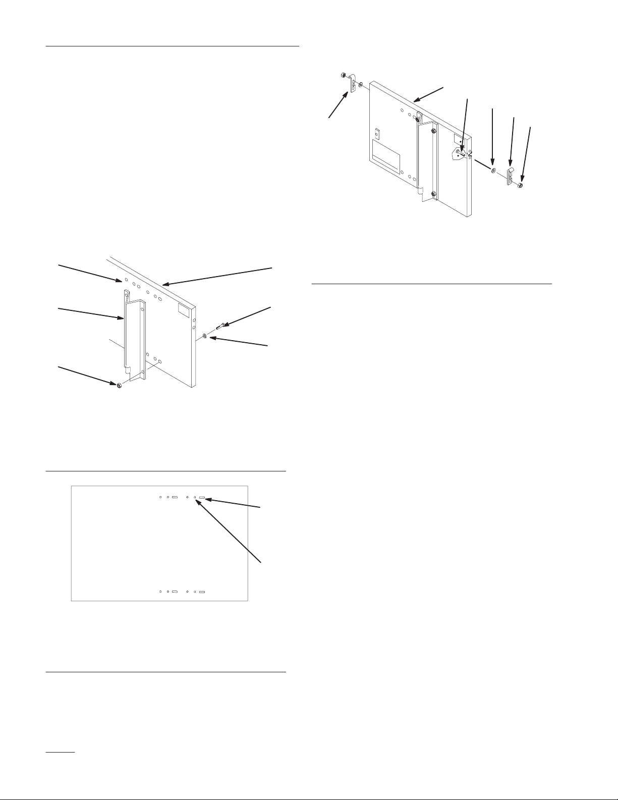
2. Hold support in position against back plate and
secure with (4) 1/4-20 x 5/8” (16 mm) bolts,
washers and (4) 1/4-20 locknuts. Install bolts
and washers from the front of back plate (Fig. 1).
1
3
5
m–4324
5
4
3
2
1
6
M–4327
Figure 3
1. Nut
2
2. Righthand Latch
3. Spring Washer
4. Bolt
5. Back Plate
6. Lefthand Latch
4
6
Figure 1
1. Select holes
2. Back plate
3. Support
4. Bolt 1/4-20 x 5/8” (16 mm)
5. Locknut 1/4-20
6. Washer
1
2
M–4328
Figure 2
1. 48” Fixed Deck 2. 36” Fixed Deck
3. Install latches to both sides of back plate. Do not
completely tighten. Latches should be able to
move up and down (Fig. 3).
2
Page 3

Installation
Assemble Bag and Frame
1. Slide upper curved portion of bagger frame into
bag and long straight rod down toward pan. Snap
“J” strips over frame rods (Fig. 4).
1
Figure 4
1. Rod 2. “J” strip
2. Arrange bag around frame and secure with (2)
handles (Fig.5 ).
3. Locate handles over slots in frame. Push (2)
1/4-20 x 1” (25 mm) bolts, through fabric from
the outside, and secure with (2) 1/4” (6 mm)
washers and (2) 1/4-20 locknuts (Fig.5 ).
m–3906
Mount Catcher to Mower
1. Tilt deflector up and slide support rod into tube
at rear of mower discharge opening (Fig. 6).
2. Hold back plate against discharge opening and
secure to mower with latch, 3/8-16 x 1” (25 mm)
bolt and 3/8-16 locknut (Fig. 6).
1
2
4
m–3903
2
3
5
Figure 6
1. Support r o d
2. Tube
3. Latch
4. Bolt 3/8-16 x 1” (25 mm)
5. Locknut 3/8-16
1
1. Handle
2. Bolt 1/4-20 x 1” (25 mm)
Figure 5
2
3
4
3. Washer 1/4” (6 mm)
4. Locknut 1/4-20
m–3905
3. Insert lower pins of bagger frame into holes in
back plate. Lift latches and slide frame side pins
into latches. Lower latches to secure (Fig. 7).
2
2
1. Back plate holes
2. Frame pin
Figure 7
3. Latch
m–3902
3
1
3
Page 4

Installation
4
 Loading...