

Page 1

ProLine
15 HP – 48I Mid-Size Mower
30197—200000001 & Up
Form No. 3323–736
Operator’s Manual
Domestic English (EN)
Page 2
Introduction
Thank you for purchasing a Toro product.
All of us at Toro want you to be completely satisfied
with your new product, so feel free to contact your
local Authorized Service Dealer for help with service,
genuine replacement parts, or other information you
may require.
Whenever you contact your Authorized Service
Dealer or the factory, always know the model and
serial numbers of your product. These numbers will
help the Service Dealer or Service Representative
provide exact information about your specific
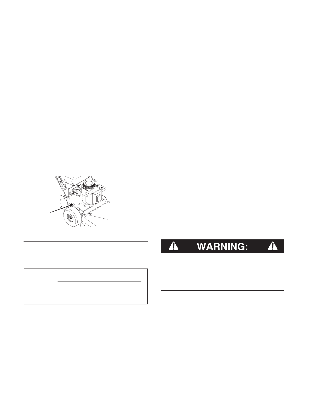
product. You will find the model and serial number
plate located in a unique place on the product as
shown below
.
1
The warning system in this manual identifies
potential hazards and has special safety messages that
help you and others avoid personal injury, even death.
DANGER, WARNING and CAUTION are signal
words used to identify the level of hazard. However,
regardless of the hazard, be extremely careful.
DANGER signals an extreme hazard that will cause
serious injury or death if the recommended
precautions are not followed.
WARNING signals a hazard that may cause serious
injury or death if the recommended precautions are
not followed.
CAUTION signals a hazard that may cause minor or
moderate injury if the recommended precautions are
not followed.
Two other words are also used to highlight
information. “Important” calls attention to special
mechanical information and “Note” emphasizes
general information worthy of special attention.
m–3775
1. Model
For your convenience, write the product model and
serial numbers in the space below.
Model No:
Serial No.
Read this manual carefully to learn how to operate
and maintain your product correctly. Reading this
manual will help you and others avoid personal injury
and damage to the product. Although we design,
produce and market safe, state-of-the-art products,
you are responsible for using the product properly
and safely. You are also responsible for training
persons, who you allow to use the product, about safe
operation.
and Serial Number Plate
The left and right side of the machine is determined
from the normal operator’s position.
The engine exhaust from this product
contains chemicals known to the State of
California to cause cancer, birth defects,
or other reproductive harm.
IMPORTANT: This engine is not equipped
with a spark arrester muffler. It is a violation
of California Public Resource Code Section
4442 to use or operate this engine on any
forest–covered, brush–covered or
grass–covered land. Other states or federal
areas may have similar laws.
The Toro Company – 1998
All Rights Reserved
Page 3

Contents
Safety 2.
Gasoline and Oil 11. . . . . . . . . . . . . . . . . . . . . . . .
Assembly 13. . . . . . . . . . . . . . . . . . . . . . . . . . . . . .
Operation 19. . . . . . . . . . . . . . . . . . . . . . . . . . . . . .
. . . . . . . . . . . . . . . . . . . . . . . . . . . . . . . .
Safe Operating Practices 2. . . . . . . . . . . . . .
Toro Mower Safety 4. . . . . . . . . . . . . . . . . .
Slope Chart 7. . . . . . . . . . . . . . . . . . . . . . . . .
Safety and Instruction Decals 9. . . . . . . . . .
Recommended Gasoline
Using Stabilizer/Conditioner 12. . . . . . . . . . .
Filling the Fuel Tank 12. . . . . . . . . . . . . . . . .
Check Engine Oil Level 12. . . . . . . . . . . . . . .
Loose Parts 13. . . . . . . . . . . . . . . . . . . . . . . . .
Install Front Castors 14. . . . . . . . . . . . . . . . . .
Install Upper Handle 14. . . . . . . . . . . . . . . . .
Connect Throttle Cable 16. . . . . . . . . . . . . . .
Install Blade Control (PTO) Rod 17. . . . . . . .
Install Shift Lever 17. . . . . . . . . . . . . . . . . . .
Mount Fuel Tank 18. . . . . . . . . . . . . . . . . . . .
Think Safety First 19. . . . . . . . . . . . . . . . . . .
Controls 19. . . . . . . . . . . . . . . . . . . . . . . . . . .
Parking Brake 20. . . . . . . . . . . . . . . . . . . . . . .
Starting and Stoppingthe Engine 21. . . . . . . .
Operating Blade Control (PTO) 22. . . . . . . . .
The Safety Interlock System 22. . . . . . . . . . .
Driving Forward or Backward 23. . . . . . . . . .
Lower Control Bar Operation 24. . . . . . . . . .
Page
11. . . . . . . . . . . . . .
Stopping the Machine 24. . . . . . . . . . . . . . . .
Adjusting Height-of-Cut 25. . . . . . . . . . . . . .
Height-of-Cut Chart 26. . . . . . . . . . . . . . . . . .
Maintenance 27. . . . . . . . . . . . . . . . . . . . . . . . . . . .
Service Interval Chart 27. . . . . . . . . . . . . . . .
Air Cleaner 28. . . . . . . . . . . . . . . . . . . . . . . . .
Engine Oil 29. . . . . . . . . . . . . . . . . . . . . . . . .
Spark Plug 31. . . . . . . . . . . . . . . . . . . . . . . . .
Cutting Blades
Tire Pressure 35. . . . . . . . . . . . . . . . . . . . . . . .
Cleaning the Cooling System 35. . . . . . . . . . .
Greasing and Lubrication 35. . . . . . . . . . . . . .
Brake 36. . . . . . . . . . . . . . . . . . . . . . . . . . . . .
Fuel Tank 37. . . . . . . . . . . . . . . . . . . . . . . . . .
Fuel Filter 38. . . . . . . . . . . . . . . . . . . . . . . . . .
Replacing the Wheel Belt 39. . . . . . . . . . . . .
Replacing the Traction Belt 39. . . . . . . . . . . .
Replacing the Mower Belt 40. . . . . . . . . . . . .
Adjusting Mower Belt Tension 41. . . . . . . . .
Adjusting the Blade Brake 41. . . . . . . . . . . . .
Adjusting Grass\Mud Scraper 42. . . . . . . . . .
Replacing the Grass Deflector 42. . . . . . . . . .
Wiring Diagram 43. . . . . . . . . . . . . . . . . . . . .
Cleaning and Storage 44. . . . . . . . . . . . . . . . .
Troubleshooting 45. . . . . . . . . . . . . . . . . . . . . . . . .
Warranty
. . . . . . . . . . . . . . . . . . . . . . . . . .
Back Cover
Page
32. . . . . . . . . . . . . . . . . . . . . .
! % ! # ! !# "
$ " "" &
" !! " #" !! !&!"!
" % "&
"! % ! # %" &# #" # "!
% ! #
"& "! & " # "
#"#
1
Page 4

Safety
This machine meets or exceeds CPSC blade safety
requirements for rotary mowers and the
B71.4 1999 specifications of the American
National Standards Institute, in effect at time of
production.
Note: The addition of certain attachments
that do not meet American National
Standards Institute certification will
cause noncertification of this machine.
Improper use or maintenance by the operator or
owner can result in injury. To reduce the potential
for injury, comply with these safety instructions
and always pay attention to the safety alert
symbol, which means CAUTION, WARNING, or
DANGER—“personal safety instruction.” Failure
to comply with the instruction may result in
personal injury or death.
Safe
The
B71.4—1999.
Operating Practices
following instructions are from ANSI standard
Preparation
• Evaluate the terrain to determine what
accessories and attachments are needed to
properly and safely perform the job. Only use
accessories and attachments approved by the
manufacturer.
• Wear appropriate clothing including hard hat,
safety glasses and ear protection. Long hair,
loose clothing or jewelry may get tangled in
moving parts.
• Inspect the area where the equipment is to be
used and remove all objects such as rocks, toys
and wire which can be thrown by the machine.
• Use extra care when handling gasoline and other
fuels. They are flammable and vapors are
explosive.
• Use only an approved container
• Never remove gas cap or add fuel with
engine running. Allow engine to cool
before refueling. Do not smoke.
Training
• Read the Operator’s Manual and other training
material. If the operator(s) or mechanic(s) can
not read English it is the owner’
to explain this material to them.
• Become familiar with the safe operation of the
equipment, operator controls, and safety signs.
• All operators and mechanics should be trained.
The owner is responsible for training the users.
• Never let children or untrained people operate or
service the equipment. Local regulations may
restrict the age of the operator.
• The owner/user can prevent and is responsible
for accidents or injuries occurring to himself or
herself, other people or property.
s responsibility
• Never refuel or drain the machine
indoors.
• Check that operator’s presence controls, safety
switches and shields are attached and
functioning properly. Do not operate unless they
are functioning properly.
2
Page 5

Safety
Operation
• Never run an engine in an enclosed area.
• Only operate in good light, keeping away from
holes and hidden hazards.
• Be sure all drives are in neutral and parking
brake is engaged before starting engine. Only
start engine from the operator’s position. Use
seat belts if provided.
• Be sure of your footing while using pedestrian
controlled equipment, especially when backing
up. Walk, don’t run. Never operate on wet grass.
Reduced footing could cause slipping.
• Slow down and use extra care on hillsides. Be
sure to travel in the recommended direction on
hillsides. Turf conditions can affect the
machine’
near drop–offs.
• Slow down and use caution when making turns
and when changing directions on slopes.
s stability
. Use caution while operating
• Look behind and down before backing up to be
sure of a clear path.
• Never carry passengers and keep pets and
bystanders away
• Slow down and use caution when making turns
and crossing roads and sidewalks. Stop blades if
not mowing.
• Be aware of the mower discharge direction and
do not point it at anyone.
• Do not operate the mower under the influence of
alcohol or drugs
• Use care when loading or unloading the machine
into a trailer or truck
• Use care when approaching blind corners,
shrubs, trees, or other objects that may obscure
vision.
.
Maintenance and Storage
• Never raise deck with the blades running.
• Never operate with the PTO shield, or other
guards not securely in place. Be sure all
interlocks are attached, adjusted properly, and
functioning property.
• Never operate with the discharge deflector
raised, removed or altered, unless using a grass
catcher.
• Do not change the engine governor setting or
overspeed the engine.
• Stop on level ground, lower implements,
disengage drives, engage parking brake (if
provided), shut off engine before leaving the
operator’s position for any reason including
emptying the catchers or unclogging the chute.
• Stop equipment and inspect blades after striking
objects or if an abnormal vibration occurs. Make
necessary repairs before resuming operations.
• Disengage drives, lower implement, set parking
brake, stop engine and remove key or disconnect
spark plug wire. Wait for all movement to stop
before adjusting, cleaning or repairing.
• Clean grass and debris from cutting units, drives,
mufflers, and engine to help prevent fires. Clean
up oil or fuel spillage.
• Let engine cool before storing and do not store
near flame.
• Shut off fuel while storing or transporting. Do
not store fuel near flames or drain indoors.
• Park machine on level ground. Never allow
untrained personnel to service machine.
• Use jack stands to support components when
required.
• Carefully release pressure from components with
stored energy.
• Keep hands and feet away from the cutting units.
3
Page 6

Safety
• Disconnect battery or remove spark plug wire
before making any repairs. Disconnect the
negative terminal first and the positive last.
Reconnect positive first and negative last.
• Use care when checking blades. Wrap the
blade(s) or wear gloves, and use caution when
servicing them. Only replace blades. Never
straighten or weld them.
• Keep hands and feet away from moving parts. If
possible, do not make adjustments with the
engine running.
• Charge batteries in an open well ventilated area,
away from spark and flames. Unplug charger
before connecting or disconnecting from battery.
Wear protective clothing and use insulated tools.
• Keep all parts in good working condition and all
hardware tightened. Replace all worn or
damaged decals.
This product is designed for cutting and recycling
grass or, when equipped with a grass bagger, for
catching cut grass. Any use for purposes other than
these could prove dangerous to user and bystanders.
Note: This engine is not equipped with a
spark arrester muffler. It is a violation
of California Public Resource Code
Section 4442 to use or operate this
engine on any forest–covered,
brush–covered or grass–covered land.
Other states or federal areas may have
similar laws.
General Operation
• Allow only responsible adults who are familiar
with the instructions to operate the machine.
• Be sure the area is clear of other people before
mowing. Stop the machine if anyone enters the
area.
Toro
The following list contains safety information
specific to Toro products or other safety information
that you must know that is not included in the ANSI
standards.
This product is capable of amputating hands and feet
and throwing objects. Always follow all safety
instructions to avoid serious injury or death.
Mower Safety
POTENTIAL HAZARD
• Engine exhaust contains carbon monoxide,
which is an odorless, deadly poison.
WHAT CAN HAPPEN
• Carbon monoxide can kill you and is also
known to the State of California to cause
birth defects.
HOW TO AV
OID THE HAZARD
• Do not run engine indoors or in an enclosed
area.
• Do not mow in reverse unless absolutely
necessary. Always look down and behind before
and while backing.
• Be aware of the mower discharge direction and
do not point it at anyone. Do not operate the
mower without either the entire grass catcher or
the guard in place.
• Slow down before turning. Sharp turns on any
terrain may cause loss of control.
• Turn off blades when not mowing.
• Keep hands, feet, hair and loose clothing away
from attachment discharge area, underside of
mower and any moving parts while engine is
running.
• Stop the engine before removing the grass
catcher or unclogging the chute.
• Mow only in daylight or good artificial light.
• Watch for traffic when operating near or crossing
roadways.
4
Page 7

Safety
• Do not touch equipment or attachment parts
which may be hot from operation. Allow to cool
before attempting to maintain, adjust or service.
• Before operating a machine with ROPS (roll
over protection) be certain the seat belts are
attached to prevent the seat from pivoting
forward.
Slope Operation
Slopes and ramps are a major factor related to
loss-of-control and tip-over accidents, which can
result in severe injury or death. All slopes and ramps
require extra caution. If you cannot back up the slope
or if you feel uneasy on it, do not mow it.
DO
• Mow up and down slopes greater than 5°, not
across.
• Mow downhill only on slopes above 10°, never
mow uphill. If a steep slope must be ascended,
back up the hill, and drive forward down the hill,
keeping the machine in gear.
• Remove obstacles such as rocks, tree limbs, etc.
from the mowing area. Watch for holes, ruts or
bumps, as uneven terrain could overturn the
machine. Tall grass can hide obstacles.
• Use slow speed so that you will not have to stop
while on the slope.
• Follow the manufacturer’s recommendations for
wheel weights or counterweights to improve
stability.
• When operating machine on slopes, banks or
near drop offs, always have ROPS (roll over
protection) installed.
• When operating a machine with ROPS (roll over
protection) always use seat belt.
• Be certain that the seat belt can be released
quickly if the machine is driven or rolls into
ponds or water.
• Check carefully for overhead clearances (i.e.
branches, doorways, electrical wires) before
driving under any objects and do not contact
them.
DO NOT
• Do not operate machine on hillsides or slopes
exceeding 15°.
• Avoid turning on slopes. If you must turn, turn
slowly and gradually downhill, if possible.
• Do not mow near drop-offs, ditches, or
embankments. The machine could suddenly turn
over if a wheel goes over the edge of a cliff or
ditch, or if an edge caves in.
• Do not mow on wet grass. Reduced traction
could cause sliding.
• Do not try to stabilize the machine by putting
your foot on the ground.
• Do not use a grass catcher on steep slopes.
Heavy grass bags could cause loss of control or
overturn the machine.
• Use extra care with grass catchers or other
attachments. These can change the stability of
the machine.
• Keep all movement on slopes slow and gradual.
Do not make sudden changes in speed or
direction.
• Avoid starting or stopping on a slope. If tires
lose traction, disengage the blades and proceed
slowly straight down the slope.
Service
• Never store the machine or fuel container inside
where there is an open flame, such as near a
water heater or furnace.
• Keep nuts and bolts tight, especially the blade
attachment bolts. Keep equipment in good
condition.
• Never tamper with safety devices. Check safety
systems for proper operation before each use.
5
Page 8

Safety
• Use only genuine replacement parts to ensure
that original standards are maintained.
• Check brake operation frequently. Adjust and
service as required.
• Battery acid is poisonous and can cause burns.
Avoid contact with skin, eyes and clothing.
Protect your face, eyes and clothing when
working with a battery.
• Battery gases can explode. Keep cigarettes,
sparks and flames away from battery.
• Hydraulic fluid escaping under pressure can
penetrate the skin and cause injury. Use
cardboard or paper to find hydraulic leaks.
• Never modify ROPS (roll over protection)
frames or structures because they are specifically
designed, sized, located and tested for injury
reduction. If a rollover occurs, a modified ROPS
will not provide adequate protection.
6
Page 9
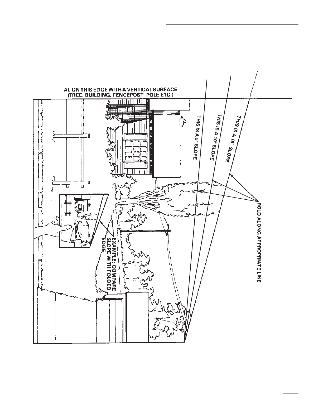
Safety
Slope
Read all safety instructions on pages 2–9.
Chart
7
Page 10

8
Page 11
Safety
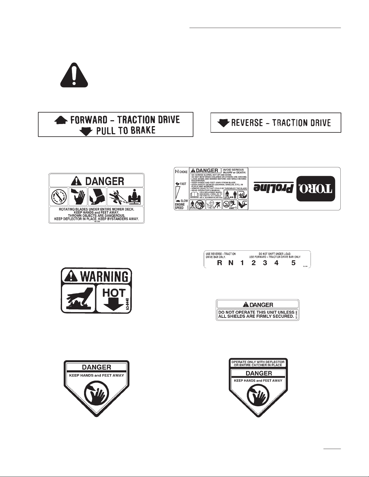
Safety
and Instruction Decals
Safety decals and instructions are easily visible to the operator and are located near
any area of potential danger. Replace any decal that is damaged or lost.
ON UPPER CONTROL BAR
(Part No. 82-2290)
ON TOP-FRONT OF MOWER
(Part No. 66-1340)
ON LOWER CONTROL BAR
(Part No. 82-2280)
ON CONTROL PANEL
(Part No. E323564)
ABOVE MUFFLER
(Part No. 63-8440)
ON TOP-LEFT SIDE OF MOWER
(Part No. 43-8480)
ON THE GEAR SELECTION PANEL
(Part No. E323560)
ABOVE GRASS DEFLECTOR
(Part No. 67-5360)
ON GRASS DEFLECTOR
(Part No. 54-9220)
9
Page 12
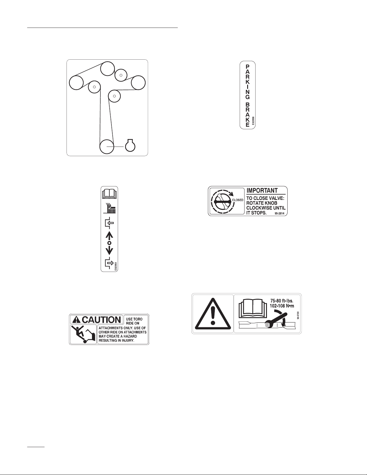
Safety
ON REAR OF MOWER
(Part No. 99-3943)
99–3943
ON LEFT SIDE OF HANDLE FRAME
(Part No. E323563)
ON PARKING BRAKE
(Part No. E323558)
ALONG LEFT SIDE OF FUEL TANK
(Part No. 95-2814)
ON REAR FRAME
(Part No. E323562)
ON REAR-LEFT CORNER OF MOWER
(Part No. 98-5130)
10
Page 13

Gasoline and Oil
Recommended
Use UNLEADED Regular Gasoline suitable for
automotive use (85 pump octane minimum). Leaded
regular gasoline may be used if unleaded regular is
not available.
IMPORTANT: Never use methanol, gasoline
containing methanol, or gasohol containing
more than 10% ethanol because the fuel
system could be damaged. Do not mix oil with
gasoline.
POTENTIAL HAZARD
Gasoline
• In certain conditions gasoline is extremely
flammable and highly explosive.
WHAT CAN HAPPEN
• A fire or explosion from gasoline can burn
you, others, and cause property damage.
HOW TO AV
OID THE HAZARD
• Use a funnel and fill the fuel tank outdoors,
in an open area, when the engine is cold.
Wipe up any gasoline that spills.
• Do not fill the fuel tank completely full.
Add gasoline to the fuel tank until the level
is 1/4” to 1/2” (6 mm to 13 mm) below the
bottom of the filler neck. This empty space
in the tank allows gasoline to expand.
• Never smoke when handling gasoline, and
stay away from an open flame or where
gasoline fumes may be ignited by a spark.
• Store gasoline in an approved container
and keep it out of the reach of children.
Never buy more than a 30-day supply of
gasoline.
POTENTIAL HAZARD
• When fueling, under certain circumstances,
a static charge can develop, igniting the
gasoline.
WHAT CAN HAPPEN
• A fire or explosion from gasoline can burn
you and others and cause property damage.
HOW TO AV
OID THE HAZARD
• Always place gasoline containers on the
ground away from your vehicle before
filling.
• Do not fill gasoline containers inside a
vehicle or on a truck or trailer bed because
interior carpets or plastic truck bed liners
may insulate the container and slow the
loss of any static charge.
• When practical, r
equipment from the truck or trailer and
refuel the equipment with its wheels on the
round.
emove gas–power
ed
• If this is not possible, then refuel such
equipment on a truck or trailer from a
portable container, rather than from a
gasoline dispenser nozzle.
• If a gasoline dispenser nozzle must be used,
keep the nozzle in contact with the rim of
the fuel tank or container opening at all
times until fueling is complete.
11
Page 14

Gasoline and Oil
POTENTIAL HAZARD
• Gasoline is harmful or fatal if swallowed.
Long–term eposure to vapors has caused
cancer to laboratory animals.
WHAT CAN HAPPEN
• Failure to use caution may result in serious
injury or illness
HOW TO AV
OID THE HAZARD
• Avoid prolonged breathing of vapors.
• Keep face away from nozzle and gas tank
or conditioner opening.
• Keep gas away from eyes and skin.
Using
Use a fuel stabilizer/conditioner in the machine to
provide the following benefits:
Stabilizer/Conditioner
Filling
1. Shut the engine off.
2. Clean around the fuel tank cap and remove the
3. Install the fuel tank cap securely. Wipe up any
Check
Before you start the engine and use the machine,
check the oil level in the engine crankcase; refer to
Checking Oil Level, page NO TAG.
the Fuel T
cap. Use a funnel and add unleaded regular
gasoline to the fuel tank, until the level is 1/4 to
1/2 inch (6 mm to 13 mm) below the bottom of
the filler neck. This space in the tank allows
gasoline to expand. Do not fill the fuel tank
completely full.
gasoline that may have spilled.
ank
Engine Oil Level
• Keeps gasoline fresh during storage of 90 days
or less. For longer storage, drain the fuel tank.
• Cleans the engine while it runs
• Eliminates gum-like varnish buildup in the fuel
system, which causes hard starting
IMPORTANT: Do not use fuel additives
containing methanol or ethanol.
Add the correct amount of gas stabilizer/conditioner
to the gas.
Note: A fuel stabilizer/conditioner is most
effective when mixed with fresh
gasoline. To minimize the chance of
varnish deposits in the fuel system, use
fuel stabilizer at all times.
12
Page 15

Assembly
Loose
Parts
Note: Use the chart below to verify all parts have been shipped.
DESCRIPTION QTY. USE
Castor assemblies
Bolt 3/8–16 x 3/4” (19 mm)
Flange nut 3/8–16
Upper handle
Bolt 3/8–16 x 1” (26 mm)
Locknut 3/8–16
Plastic terminal
Wire tie
Rod fitting
Clevis pin
Washer 1/4”
Hairpin cotter
PT
O rod
Hairpin cotter
2
8
8
1
4
4
1
1
2
2
2
4
1
2
Install front castors to mower
Install upper handle to frame
Install wire harness to handle
Install traction control rods
Install PT
O rod
Shift lever
Rubber seal
Square hole washer
Spring washer
Locknut
1
1
1
1
1
Install shift lever to transmission
13
Page 16
Assembly
DESCRIPTION USEQTY.
Fuel tank
Bolt 5/16–1/ x 7/8” (22.5 mm)
Lock washer 5/16”
W
asher 5/16”
Stud
Spring
Hose clamp
Operator’
Engine Operator
s Manual
’
s Manual
Parts Catalog
Registration card
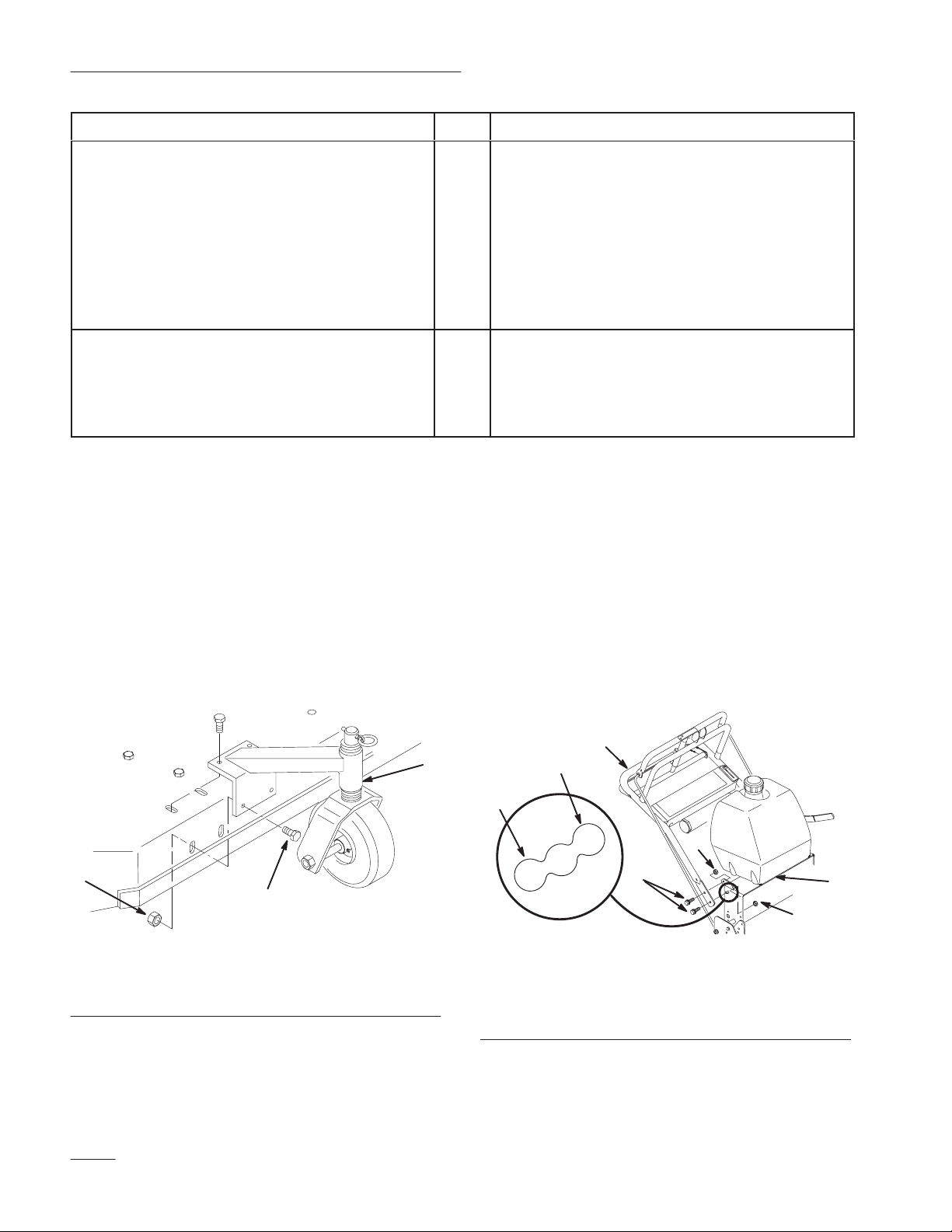
Install
Front Castors
1. Align castors with holes on top and front of
mower and insert (8) 3/8–16 x 3/4” (19 mm)
bolts through mower. Secure with (8) 3/8–16
flange nuts below mower (Fig. 1).
1
2
2
4
Install fuel tank
2
2
1
1
Read before operating machine
1
1
Fill out and return to T
oro
1
Install
Upper Handle
1. Position handle outside frame and align upper
handle mounting holes with desired mounting
holes in rear frame. High, medium or low
according to operators height (Fig. 2).
Note: Tighten lower bolts first to pull castor
against front, then top bolts last.
2. Torque bolts to 30–35 ft. lb. (40–47 NSm).
Figure 1
1. Front
2. Bolt
castor
3/8–16 x
3/4” (19 mm)
3. Flange
nut 3/8–16
m–3777
2. Secure each side with (2) 3/8–16 x 1” (26mm)
bolts and (2) 3/8–16 locknuts (Fig. 2).
3. Torque bolts to 25 ft. lbs. (34 NSm).
1. Upper
2.
Rear frame
3.
Bolt 3/8–16 x 1” (26mm)
handle
Figure 2
4.
Locknut 3/8
5. Low
6. High
m–4213
14
Page 17

Assembly
Connect Wire Harness
4. Route wire harness inside of frame, along left
handle and over throttle cable. Compress wire
harness covering and press into lower and upper
holes in rear of control panel (Fig. 3).
5. Thread harness up through rear tube of traction
handle (Fig. 3).
m–3774
Figure 3
1. Wire
2.
6. Insert terminals into plastic plug until the clips
harness
Control panel
3. Tube
Wire tie
4.
snap into position (Fig. 3). If they do not snap
turn around and try again.
Install Traction Control Rods
1. Thread trunnions equal distance onto each
control rod. For a starting point thread on
approximately 2 in. (51 mm) (Fig. 5).
2. With trunnion rod up, slide clevis pins through
rod fittings and mounting holes in idler brackets
(from outside) (Fig. 5). Secure with 1/4” (6 mm)
washers and hairpin cotters (Fig. 5).
1. Control
2. Trunnion
3.
Idler bracket
rod
Figure 5
4.
5. W
6.
Clevis pin
asher 1/4” (6 mm)
Hairpin cotter
m–3785
7. Push plug onto switch so latches interlock (Fig.
3).
8. Secure wire harness and throttle cable to left
handle, away from PTO lever, with wire tie
(Fig. 3).
1. Terminal
2. Clip
Figure 4
3. Plastic
4. Switch
m–3782
plug
15
Page 18

Assembly
3. Check the gap between upper control bar and
fixed bar with wheel drive fully engaged. Gap
should be approximately 1 to 1-1/4 in.
(25–32 mm) (Fig. 6).
Note: The upper control bar and fixed bar
must be parallel in the engaged,
relaxed and brake positions.
4. Check operation. If adjustment is required,
remove hairpin cotter securing rod to upper
control bar. Thread rod in or out of fitting for
proper position and install into upper control bar
with hairpin cotter.
5. After adjusting control rods, check parking brake
adjustment, refer to: Brake page 36 for
instructions.
Connect
Throttle Cable
1. Place throttle control lever in FAST
position.(Fig. 7).
2. Hook wire Z–bend into hole of speed control
lever (Fig. 7).
3. Loosen cable clamp screw allowing cable
installation, but do not tighten (Fig. 7).
4. Move control cable casing and wire until hole in
speed control lever is aligned with hole in base
plate. Insert a 1/4 in. (6.35 mm) diameter pin or
bolt into aligned holes to hold adjustment.
5. Pull throttle cable slightly to remove any slack
and tighten cable clamp screw to lock
adjustment in place.
6. Remove alignment pin and check control
operation.
1. Control
2.
Fixed control bar
rod
Figure 6
3.
Parking brake lever
4.
Upper control bar
m–3770
m–2596
Figure 7
1. Wire
2.
3.
Z-bend
Speed control lever
Base plate
4.
Alignment holes 1/4 in.
(6.35mm)
Cable clamp
5.
16
Page 19

Assembly
Install
Blade Control (PT
O)
Rod
1. Rotate blade control lever (PTO) vertical away
from left handle so rod drops down.
2. Remove hairpin cotters from bottom end of
blade control rod (PTO) (Fig. 8).
3. Secure blade control (PTO) rod through hole in
bellcrank with hairpin cotters (Fig. 8).
1. Blade
2.
control lever
Blade control rod
Figure 8
3. Bellcrank
4.
Hairpin cotter
m–3783
Install
Shift Lever
1. Remove the 3/8” locknut and spring disk washer
from the stud on top of the transmission.
Note: Do not remove rubber seal washer and
square hole washer from transmission
shaft.
2. Slide shift lever through control panel and align
mounting hole in lever with square on
transmission shaft. Secure lever to transmission
with previously removed spring washer and
locknut (Fig. 9).
3. Replace the spring washer,dish down, and
locknut (Fig. 8).
4. Torque nut to 35 ft. lbs. (47 NSm).
5. Shift lever to second gear and check alignment
of lever in slot of shifter plate. Clearance
between top of lever and the top of the slot
should be about equal to the clearance between
bottom of the lever and the bottom of the slot.
6. If clearance is not correct, remove lever and bend
it slightly to adjust.
Note: Do not bend lever while attached to
transmission shaft or damage may
occur.
Figure 9
1. Shift
2.
3.
lever
Control panel
Rubber seal washer
4.
Square hole washer
5.
Spring washer
6.
Locknut 3/8
m–3772
17
Page 20

Assembly
Mount
Fuel T
ank
1. Align fuel tank to top of rear frame and secure
fuel tank right side with (2) 5/16–18 x 7/8 in.
(22.5 mm) bolts, (2) 5/16 lock washers and (2)
5/16 washers (Fig. 10).
2. Secure fuel tank left side to frame with (2)
5/16–18 x 7/8 in. (22.5 mm) studs, (2) 5/16
washers and (2) 5/16 locknuts (Fig. 10).
3
2
m–37711
3. Push fuel line onto fuel tank fitting and secure
with hose clamp (Fig. 11).
1
23
1. Fuel
2.
Hose clamp
Figure 1
line
1
3.
Fuel fitting
4
3
5
6
m–3778
1. Bolt
5/8–18 x 7/8”
(22.5 mm)
2.
Lock washer 5/16
3. W
asher 5/16
Figure 10
4. Stud
5. Spring
6. Locknut
18
Page 21

Operation
Think
Safety First
Please carefully read all the safety instructions and
symbols in the safety section. Knowing this
information could help you, pets or bystanders avoid
injury.
Controls
Become familiar with all the controls (Fig. 12) before
you start the engine and operate the machine.
Throttle Control – The throttle control has CHOKE,
FAST, SLOW and STOP positions.
Bail – The bail, in conjunction with the PTO switch,
allows the engine to be started with the PTO
disengaged. With the bail compressed the blade
control (PTO) can be engaged. Release the bail with
the PTO engaged and the engine stops.
Blade Control (PTO) – The blade control lever
(PTO) engages and disengages power to the mower
blades. Move the PTO lever forward to engage the
blades. Pull rearward to stop driving mower blades
Gear Shift Lever – Transmission has five forward
speeds, neutral and reverse, and has an in-line shift
pattern. Do not shift while unit is moving, as
transmission damage may occur.
Recoil Starter – Pull recoil starter handle to start
engine.
Fuel Shut–off Valve – (In fuel line) Close fuel
shut–off valve when transporting or storing mower.
2
7
3
1
4
m–4194
Figure 12
1. Throttle
2. Bail
3.
4.
control
Blade control (PT
Gear shift lever
O)
5.
Upper control bar
6.
Lower control bar
7.
Parking brake lever
5
6
Upper Control Bar – Shift to desired gear and push
forward on control bar to engage forward traction
operation and pull back to brake. Pull right side of
control bar to turn right and left side to turn left.
Lower Control Bar – Shift transmission to reverse
and pull rearward on lower control bar to engage
rearward traction operation.
Parking Brake Lever – Pull back on upper control
bar and swing brake lever up against the upper handle
to keep brake engaged.
19
Page 22

Operation
Parking Brake
Always set the parking brake when you stop the
machine or leave it unattended.
Setting the Parking Brake
1. Pull the upper control bar rearward and hold it in
this position (Fig. 13).
2. Lift the parking brake lock up and gradually
release the upper control bar (Fig. 13). The brake
lock should stay in the set (locked) position.
Releasing the Parking Brake
1. Pull rearward on the upper control bar (Fig. 13).
Lower the parking brake lock to the released
position.
2. Gradually release the upper control bar.
2
Figure 13
1. Upper
control bar
2.
Parking brake lock
1
m–4212
20
Page 23
Operation
Starting
and Stopping
the Engine
Starting
1. Make sure spark plug wire(s) are installed on
spark plug(s) and fuel valve is open.
2. Move the blade control to off, the shift lever to
neutral and set the parking.
3. Move the throttle control to CHOKE position
before starting a cold engine.
Note: A warm or hot engine usually does not
require any choking. To start a warm
engine, move throttle control to FAST
position.
4. Grasp recoil starter handle firmly and pull out
until positive engagement results; then pull
handle vigorously to start engine. Allow rope to
recoil slowly.
IMPORTANT: Do not pull recoil rope to its
limit or let go of the starter handle when rope
is pulled out because rope may break or recoil
assembly may be damaged.
Stopping
1. Move the throttle lever midway between FAST
and SLOW (Fig. 14).
Note: Allow the engine to run a minimum of
15 seconds and then stop the engine.
2. To stop the engine pull the throttle all the way
back, past SLOW(Fig. 14).
1
2
m–4194
Figure 14
1. Blade
3. Set the parking brake.
4. Pull wire off spark plug(s) to prevent possibility
control (PT
O) 2.
Throttle lever
of accidental starting before storing machine.
5. Close fuel shut off valve before storing machine.
IMPORTANT: Make sure fuel shut off valve
is closed before transporting or storing
machine, or fuel leakage may occur.
21
Page 24

Operation
Operating
The blade control (PTO) lever engages and
disengages power to the mower blades.
Blade Control (PT
O)
Engaging the Mower Blades (PTO)
1. Pull on the upper control bar to stop the machine
(Fig. 15).
2. Hold the bail against the upper control bar
(Fig. 15).
3. To engage blade(s), push the blade control lever
firmly forward, until it latches over-center
(Fig. 15).
1
3
2
The
Safety Interlock System
Understanding the Safety Interlock
System
The safety interlock system is designed to prevent the
engine from starting if:
• The throttle lever is all the way back, past
SLOW
• The blade control lever (PTO) is engaged
The safety interlock system is also designed to stop
the engine if you released the bail with the PTO
engaged or move the throttle all the way back, past
SLOW.
Testing the Safety Interlock System
Test the safety interlock system before you use the
machine each time. If the safety system does not
operate as described below, have an Authorized
Service Dealer repair the safety system immediately.
Figure 15
1. Upper
2. Bail
control bar
Blade control (PT
3.
O)
Disengaging the Mower Blades (PTO)
1. To disengage the blade(s), pull blade control
lever rearward, all the way (Fig. 15).
Note: It is necessary to fully and manually
disengage mower
.
m–4194
1. Set the parking brake, disengage the PTO and
place the throttle forward. Start the engine. With
the engine running squeeze the bail against upper
control bar and push the mower blade control
lever forward. The mower blades begin rotating.
2. With the engine running, release the bail. The
engine should stop.
3. Start the engine again.
4. With the engine running, move the throttle lever
all the way back, past SLOW. The engine should
stop.
22
Page 25

Operation
Driving
Forward or Backward
The throttle control regulates the engine speed as
measured in rpm (revolutions per minute). Place the
throttle control in the “FAST” position for best
performance.
Forward
1. To go forward, move the shift lever to a forward
gear.
2. Release the parking brake: refer to Releasing the
Parking Brake, page 20.
3. Slowly press on the upper control bar to move
forward (Fig. 16).
To go straight, apply equal pressure to both ends of
the upper control bar (Fig. 16).
To turn, release pressure on the upper control bar side
toward the direction you want to turn (Fig. 16).
Backward
1. To go backward, move the shift lever to reverse
gear.
2. Release the parking brake: refer to Releasing the
Parking Brake, page 20.
3. Slowly squeeze on the lower control bar and
handle together to move rearward (Fig. 16).
1. Upper
control bar
Figure 16
2.
1
2
m–4194
Lower control bar
23
Page 26

Operation
Lower
Control Bar Operation
This procedure is for driving up a curb. This can be
performed while driving forward or backward.
1. Disengage the mower blades.
POTENTIAL HAZARD
• A blade can be bent or damaged when
driving up a curb. Blades could break
apart and pieces could be thrown at
bystanders or at you as you use the mower.
WHAT CAN HAPPEN
• Pieces of blade that may be thrown could
seriously injure or kill you or bystanders.
HOW TO AV
OID THE HAZARD
• Do not run blades while driving up a curb
forward or backward.
2. Select first gear or reverse to drive machine.
1
2
m–4185
1. Lower
Control Bar
engaged and mower in
reverse.
Stopping
Figure
the Machine
18
2.
Pull up to assist machine
To stop the machine apply the brakes, pull back on
the upper control bar, release the bail and set the
parking brake; refer to Setting the Parking Brake,
page 20.
3. Drive machine until drive wheels contact curb
(Fig. 18).
Note: Both drive wheels should contact the
curb and castor wheels straight.
4. At the same time engage lower control bar and
lift up on handle (Fig. 17 and 18).
Note: Lifting up on handle will assist driving
the machine up a curb and not spin the
drive wheels.
1
1. Lower
(Engaged)
Control Bar
2
Figure 17
2. Handle
m–4192
24
Page 27

Operation
Adjusting
Height-of-Cut
A 1” to 4-1/4” range for height-of-cut can be achieved
by adjusting blade spacers, rear axle height and front
castor spacers. Use the Height-of-Cut chart on page
26 to select the combination required
Adjust Blade Height
Blades are adjusted by using the four, 1/4” spacers
found on the blade spindle bolts. This allows a range,
in 1/4” increments, of cutting height in any axle
position. The same number of blade spacers must be
used on all blades to achieve a level cut (two above
and two below, one above and three below, etc.).
1. Stop engine and remove spark plug wire(s).
2. Hold blade bolt and remove nut. Slide bolt
down, through spindle, and change spacers as
required (Fig. 19).
Adjust Axle Height
Desired height-of-cut range can be obtained by
adjusting the rear axle and placing caster spacers
above or below the caster arm (see chart).
1. Stop engine and remove spark plug wire(s).
2. Loosen but do not remove the (2) axle pivot
bolts and the (2) axle adjustment bolts (Fig. 20).
3. Place a jack under the rear center of the engine
frame. Raise the back end of the engine frame up
enough to remove front (2) axle adjustment bolts
(Fig. 20).
4. Raise or lower the engine frame with the jack,so
that front (2) axle adjustment bolts can be
installed in the desired hole location (Fig. 20). A
tapered punch can be used to help align the
holes.
5. Tighten all (4) bolts and lower the unit.
3. Insert bolt, add extra spacer(s), and secure with
thin washer and nut (Fig. 19).
4. Torque blade bolt to 75–80 ft. lb.
(101–108 NSm).
4
1
2
1. Blade
2. Blade
3.
Cone washer
4. Spacer
bolt
3
Figure 19
5. Tube
6.
7. Nut
m–3779
Thin washer
6. Adjust control rods and brake linkages as
required, refer to: Assembly and Brake.
IMPORTANT: It will be necessary to adjust
control rods and brake linkage when
changing axle positions for proper traction
7
6
4
5
and brake function.
1
1. Axle
pivot bolt
2
Figure 20
2.
A
B
C
D
E
m–3789
Axle adjustment bolt
25
Page 28

Operation
Axl
Adjust Caster Position
1. Using the height-of-cut chart, adjust the caster
spacers to match with the axle hole selected
(Fig. 21).
2. Remove clevis pin, slide castor from support and
change spacers(Fig. 21).
3. Install castor in support and insert clevis
pin(Fig. 21).
Height-of-Cut
No.
e
Position
Below Caster
1/2″ 3/16″ 4 3210
Chart
of Spacers
Number of 1/4
1. Clevis
2.
pin
3/16” (5 mm) spacer
″ Blade
2
Figure 21
3.
1/2” (13 mm) spacer
Spacers Below Spindle
1
3
m–3791
A 0 0 1” 1–1/4” 1–1/2” 1–3/4” 2”
A 0 1 1–1/8” 1–3/8” 1–5/8” 1–7/8” 2–1/8”
A 1 0 1–3/8” 1–5/8” 1–7/8” 2–1/8” 2–3/8”
B 0 1 1–3/8” 1–5/8” 1–7/8” 2–1/8” 2–3/8”
B 1 0 1–5/8” 1–7/8” 2–1/8” 2–3/8” 2–5/8”
B 1 1 1–3/4” 2” 2–1/4” 2–1/2” 2–3/4”
B 2 0 2” 2–1/4” 2–1/2” 2–3/4” 3”
C 1 1 1–7/8” 2–1/8” 2–3/8” 2–5/8” 2–7/8”
C 2 0 2–1/8” 2–3/8” 2–5/8” 2–7/8” 3–1/8”
C 2 1 2–1/4” 2–1/2” 2–3/4” 3” 3–1/4”
C 3 0 2–1/2” 2–3/4” 3” 3–1/4” 3–1/2”
D 2 1 2–3/8” 2–5/8” 2–7/8” 3–1/8” 3–3/8”
D 3 0 2–1/2” 2–3/4” 3” 3–1/4” 3–1/2”
D 3 1 2–3/4” 3” 3–1/4” 3–1/2” 3–3/4”
D 4 0 3” 3–1/4” 3–1/2” 3–3/4” 4”
E 3 1 2–7/8” 3–1/8” 3–3/8” 3–5/8” 3–7/8”
E 4 0 3–1/8” 3–3/8” 3–5/8” 3–7/8” 4–1/8”
E 4 1 3–1/4” 3–1/2” 3–3/4” 4” 4–1/4”
26
Page 29

Maintenance
Service
Service Operation
Oil—check level
Oil—change* Initial X X
Oil Filter–change (200 hours or every
other oil change)
Safety System—check
Brakes—check X X
Cutting Blades – check
Wheel Bearings—grease*
T
ransmission Couplers – grease*
Idler Pivots – grease*
Belt Blade Idler Pivots – grease*
Foam Air Cleaner—service*
Paper Air Cleaner—replace*
Spark Plug(s)—check
Belts—check for wear/cracks
PT
O Belt—check tension
Gasoline—drain X
Engine—clean cooling system
Fuel Filter—replace
T
ires—check pressure
Chipped Surfaces—paint
Interval Chart
Each
Use8Hours25Hours50Hours
X X
X X
X X X
X X
X X
X X
X X
X X
X X
Initial X X
X X X
X X
100
Hours
X X
200
Hours
X X
X X
X X
Storage
Service
X
*
More often in dusty
, dirty conditions
27
Page 30

Maintenance
Air
Cleaner
Service Interval/Specification
Foam Element: Clean and re-oil after every 25
operating hours.
Paper Element: Replace after every 100 operating
hours.
Note: Service the air cleaner more frequently
(every few hours) if operating
conditions are extremely dusty or
sandy.
Removing the Foam and Paper Elements
1. Disengage the power take off (PTO), set the
parking brake, and turn the ignition key to
“OFF” to stop the engine. Remove the key.
2. Clean around the air cleaner to prevent dirt from
getting into the engine and causing damage.
Unscrew the cover nut and remove the air
cleaner cover (Fig. 22).
3. Remove the air cleaner assembly (Fig. 22).
Cleaning the Foam and Paper Elements
1. Foam Element
A. Wash the foam element in liquid soap and
warm water. When the element is clean,
rinse it thoroughly.
B. Dry the element by squeezing it in a clean
cloth.
C. Put one or two ounces of oil on the element
(Fig. 23). Squeeze the element to distribute
the oil.
IMPORTANT: Replace the foam element if it
is torn or worn.
2
1
m–1213
Figure 23
1. Foam
element
2. Oil
4. Carefully slide the foam element off the paper
element (Fig. 22).
1
2
3
4
5
6
m–2595
Figure 22
1. Cover
2.
3.
and nut
Wing nut
Foam element
4. W
asher and grommet
5.
Paper element
6.
Air cleaner base
28
Page 31
Maintenance
2. Paper Element
A. Lightly tap the element on a flat surface to
remove dust and dirt (Fig. 24).
B. Inspect the element for tears, an oily film,
and damage to the rubber seal.
IMPORTANT: Never clean the paper element
with pressurized air or liquids, such as
solvent, gas, or kerosene. Replace the paper
element if it is damaged, defective, or cannot
be cleaned thoroughly.
Engine
Oil
Service Interval/Specification
Change oil:
• After the first 8 operating hours.
• After every 100 operating hours.
Note: Change oil more frequently when
operating conditions are extremely
dusty or sandy.
Oil Type: Detergent oil (API service SF, SG or SH)
Crankcase Capacity: w/filter, 2 qt. (1.9 l)
Viscosity: See table below
1
USE THESE SAE VISCOSITY OILS
2
m–1213
Figure 24
1. Paper
element
2.
Rubber seal
Installing the Foam and Paper Elements
1. Installing the Foam and Paper Elements
IMPORTANT: To prevent engine damage,
always operate the engine with the complete
foam and paper air cleaner assembly
installed.
1. Carefully slide the foam element onto the paper
air cleaner element (Fig. 22).
2. Place the air cleaner assembly onto the air
cleaner base (Fig. 22).
5W–20, 5W–30
–20 0 20
°
F
–30°–20 –10
C
10W–30, 10W–40
40 60
32
01020
80 100
30 40
3. Install the air cleaner cover and secure with
cover nuts (Fig. 22).
29
Page 32

Maintenance
Checking Oil Level
1. Park the machine on a level surface, disengage
the power take off (PTO), set the parking brake,
and turn the ignition key to “OFF” to stop the
engine. Remove the key.
2. Clean around the oil dipstick (Fig. 25) so dirt
cannot fall into the filler hole and damage the
engine.
3. Unscrew the oil dipstick and wipe the metal end
clean (Fig. 25).
4. Slide the oil dipstick fully into the filler tube, do
not thread onto tube (Fig. 25). Pull the dipstick
out and look at the metal end. If oil level is low,
slowly pour only enough oil into the filler tube
to raise the level to the “FULL” mark.
IMPORTANT: Do not overfill the crankcase
with oil because the engine may be damaged.
Changing/Draining Oil
1. Start the engine and let it run five minutes. This
warms the oil so it drains better.
2. Park the machine so that the drain side is slightly
lower than the opposite side to assure the oil
drains completely. Then disengage the power
take off (PTO), set the parking brake, and turn
the ignition key to “OFF” to stop the engine.
Remove the key.
3. Place a pan below the oil drain. Remove the oil
drain cap (Fig. 26).
4. When oil has drained completely, install the oil
drain cap.
Note: Dispose of the used oil at a certified
recycling center.
1. Oil
2.
Metal end
1
3
dipstick
2
Figure 25
3.
Filler tube
1
m-4758
Figure 26
1. Oil
drain cap
5. Slowly pour approximately 80% of the specified
amount of oil specified, page 29, into the filler
tube (Fig. 25). Now check the oil level; refer to
Checking Oil Level, page 30. Slowly add
additional oil to bring to “FULL” mark on
dipstick.
30
Page 33

Maintenance
Change Oil Filter
Service Interval/Specification
Replace the oil filter every 200 hours or every other
oil change.
Note: Change oil filter more frequently when
operating conditions are extremely
dusty or sandy.
1. Drain the oil from the engine; refer to
Changing/Draining Oil, page 30.
2. Remove the old filter and wipe the filter adapter
(Fig. 27) gasket surface.
3. Apply a thin coat of new oil to the rubber gasket
on the replacement filter (Fig. 27).
1
Spark
Plug
Service Interval/Specification
Check the spark plug(s) after every 200 operating
hours. Make sure the air gap between the center and
side electrodes is correct before installing the spark
plug. Use a spark plug wrench for removing and
installing the spark plug(s) and a gapping tool/feeler
gauge to check and adjust the air gap. Install a new
spark plug(s) if necessary.
Type: Champion RC12YC (or equivalent) Air Gap:
0.040 in. (1.02 mm)
Removing the Spark Plug(s)
1. Disengage the power take off (PTO), set the
parking brake, and turn the ignition key to
“OFF” to stop the engine. Remove the key.
2. Pull the wire(s) off the spark plug(s) (Fig. 28).
Now clean around the spark plug(s) to prevent
dirt from falling into the engine and potentially
causing damage.
3
2
m–1256
Figure 27
1. Oil
filter
2. Gasket
3. Adapter
4. Install the replacement oil filter to the filter
adapter. Turn the oil filter clockwise until the
rubber gasket contacts the filter adapter, then
tighten the filter an additional 1/2 turn (Fig. 27).
5. Fill the crankcase with the proper type of new
oil; refer to Changing/Draining Oil, page 30.
3. Remove the spark plug(s) and metal washer.
2
1
Figure 28
1. Spark
plug wire
2.
Spark plug
m–4757
31
Page 34

Maintenance
Checking the Spark Plug
1. Look at the center of the spark plug(s) (Fig. 29).
If you see light brown or gray on the insulator,
the engine is operating properly. A black coating
on the insulator usually means the air cleaner is
dirty.
IMPORTANT: Never clean the spark plug(s).
Always r
a black coating, worn electrodes, an oily film,
or cracks.
2. Check the gap between the center and side
electrodes (Fig. 29). Bend the side electrode
(Fig. 29) if the gap is not correct.
2
eplace the spark plug(s) when it has:
3
1
0.040
in.
(1.02 mm)
Cutting
Blades
To ensure a superior quality of cut, keep the blades
sharp. For convenient sharpening and replacement,
you may want to keep extra blades on hand.
POTENTIAL HAZARD
• A blade that is worn or damaged could
break apart and pieces could be thrown at
bystanders or at you as you use the mower.
WHAT CAN HAPPEN
• Pieces of blade that may be thrown could
seriously injure or kill you or bystanders.
HOW TO AV
OID THE HAZARD
• Periodically inspect the blade for wear and
damage. Immediately install a new blade if
it is worn or damaged.
29
3.
Air gap (not to scale)
1. Center
2.
Side electrode
Figure
electrode insulator
Installing the Spark Plug(s)
1. Install the spark plug(s) and metal washer. Make
sure the air gap is set correctly.
2. Tighten the spark plug(s) to 20 ft-lb (27 N.m).
3. Push the wire(s) onto the spark plug(s) (Fig. 28).
Before Inspecting or Servicing the
Blades
Park the machine on a level surface, disengage the
blade control (PTO) and set the parking brake.
32
Page 35

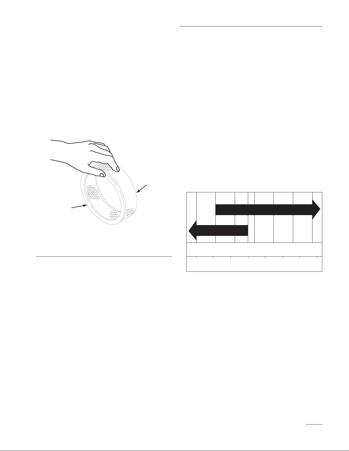
Inspecting the Blades
1. Inspect the cutting edges (Fig 30). If the edges
are not sharp or have nicks, remove and sharpen
the blades. Refer to Sharpening the Blades on
page 34.
2. Inspect the blades, especially the curved area
(Fig. 30). If you notice any damage, wear, or a
slot forming in this area (item 3 in Fig. 30),
immediately install a new blade.
2
1
Maintenance
Figure
32
m–2539
2. Rotate the opposite ends of the blades forward.
Measure from a level surface to the cutting edge
of the blades at the same position as in step 1
above. The difference between the dimensions
obtained in steps 1 and 2 must not exceed 1/8”
(3 mm). If this dimension exceeds 1/8” (3 mm),
the blade is bent and must be replaced. Refer to
Removing the Blades, and Installing the Blades
on page 34.
3
m–151
Figure 30
1. Cutting
2.
Edge
Curved Area
3. W
ear/slot Forming
Checking for Bent Blades
1. Rotate the blades until the ends face forward and
backward (Fig. 31). Measure from a level
surface to the cutting edge of the blades
(Fig. 32). Note this dimension.
POTENTIAL HAZARD
• A blade that is bent or damaged could
break apart and pieces could be thrown at
bystanders or at you as you use the mower.
WHAT CAN HAPPEN
• Pieces of blade that may be thrown could
seriously injure or kill you or bystanders.
HOW TO AV
•
Always r
OID THE HAZARD
eplace bent or damaged blade with
a new blade.
• Never file or create sharp notches in the
edges or surfaces of blade.
Figure 31
m–1078
33
Page 36

Maintenance
Removing the Blades
Blades must be replaced if a solid object is hit, if the
blade is out of balance or is bent. To ensure optimum
performance and continued safety conformance of the
machine, use genuine TORO replacement blades.
Replacement blades made by other manufacturers
may result in non-conformance with safety standards.
Hold the blade bolt with a wrench. Remove the nut,
blade bolt, cone washer, blade, spacers and thin
washer from the spindle (Fig. 33).
4
1
2
1. Blade
2. Blade
3.
Cone washer
4. Spacer
bolt
3
Figure 33
5. Tube
6.
7. Nut
m–3779
Thin washer
Sharpening the Blades
1. Use a file to sharpen the cutting edge at both
ends of the blade (Fig. 34). Maintain the original
angle. The blade retains its balance if the same
amount of material is removed from both cutting
edges.
2
1
m–1854
7
6
4
1. Sharpen
at original angle
2. Check the balance of the blade by putting it on a
blade balancer (Fig. 35). If the blade stays in a
horizontal position, the blade is balanced and can
5
be used. If the blade is not balanced, file some
metal off the end of the sail area only (Fig. 34).
Repeat this procedure until the blade is balanced.
1
1. Blade 2. Balancer
Figure 34
2. Sail
2
m–1855
Figure 35
34
Installing the Blades
1. Place the blade onto the bolt, over cone washer.
Select proper number of spacer(s) for
height-of-cut and slide bolt into spindle (Fig.
33).
IMPORTANT: The curved part of the blade
must be pointing upward toward the inside of
the mower to ensure proper cutting.
2. Install remaining spacer(s) and secure with thin
washer and nut (Fig. 33).
3. Torque the blade bolt to 75–80 ft. lb.
(101–108 NSm).
Page 37

Tire
Pressure
Greasing
Maintenance
and Lubrication
Service Interval/Specification
Maintain the air pressure in the front and rear tires as
specified. Check the pressure at the valve stem after
every 50 operating hours or monthly, whichever
occurs first (Fig. 36). Check the tires when they are
cold to get the most accurate pressure reading.
Pressure: 15 psi (103 kPa) rear tires
25–30 psi (172–207 kPa) castor tires
1
Figure 36
1. Valve
stem
Service Interval/Specification
Grease the areas shown and at intervals in Where to
Add Grease section below. Grease more frequently
when operating conditions are extremely dusty or
sandy.
Grease Type: General-purpose grease.
How to Grease
1. Disengage the blade control (PTO) and set the
parking brake.
2. Clean the grease fittings with a rag. Make sure to
scrape any paint off the front of the fitting(s).
3. Connect a grease gun to the fitting. Pump grease
into the fittings until grease begins to ooze out of
the bearings.
4. Wipe up any excess grease.
Where to Add Grease
Cleaning
the Cooling System
Service Interval/Specification
Before each use, check and clean engine cooling
system. Remove any build–up of grass, dirt or other
debris from the cylinder and cylinder head cooling
fins, air intake screen on flywheel end, and
carburetor–governor levers and linkage. This will
help insure adequate cooling and correct engine speed
and will reduce the possibility of overheating and
mechanical damage to the engine.
1. Lubricate the drive and castor wheel bearings
and front spindles (Fig. 37). Lubricate every 8
hours.
m–3780
Figure 37
35
Page 38

Maintenance
2. Lubricate the transmission couplers every 50
hours and idler arm pivots every 8 hours
(Fig 38).
1
2
Figure 38
1. Idler
Arm Pivots
(Lubricate after 8 hours)
2. T
ransmission Couplers
(Lubricate after 50 hours)
3. Lubricate the blade belt idler arm pivot.
(Fig. 39). Lubricate every 50 hours.
m–3797
Brake
Service Interval/Specification
Before each use, check brakes for proper operation.
Always set the parking brake when you stop the
machine or leave it unattended. If the parking brake
does not hold securely, an adjustment is required.
Checking the Brake
1. Park the machine on a level surface, disengage
the blade control (PTO) and set the parking
brake.
2. Rear wheels must lock when you try to push the
machine forward or backward. Adjustment is
required if the wheels turn and do not lock; refer
to Adjusting the Brake, page 37.
3. Release the brake and press upper control bar
very lightly, approximately 1/2 in. (13 mm),
wheels should rotate freely.
Figure 39
4. If both conditions are met, no adjustment is
required.
m–4731
36
Page 39

Maintenance
Adjusting the Brake
The brake lever is on the upper control bar (Fig. 12).
If the parking brake does not hold securely, an
adjustment is required.
1. Check the brake before you adjust it; refer to
Checking the Brake, page 36.
2. Release the parking brake; refer to Releasing the
Parking Brake, page 20.
3. To adjust brake set the parking brake latch, and
rotate the wing nuts on the brake rods (Fig. 40).
Clockwise to tighten the brake and
counterclockwise to loosen the brake.
Note: Control bar should be parallel with
reference bar when properly adjusted.
4. Check the brake operation again; refer to
Checking the Brake, page 36.
IMPORTANT: With the parking brake
released, the rear wheels must rotate freely
when you push the mower. If brake action
and free wheel rotation cannot be achieved
contact your service dealer immediately.
Fuel Tank
Draining The Fuel Tank
POTENTIAL
• In certain conditions gasoline is extremely
flammable and highly explosive.
WHAT CAN HAPPEN
• A fire or explosion from gasoline can burn
you, others, and cause property damage.
HOW TO AV
• Drain gasoline from the fuel tank when the
engine is cold. Do this outdoors in an open
area. Wipe up any gasoline that spills.
• Never drain gasoline near an open flame or
where gasoline fumes may be ignited by a
spark.
• Never smoke a cigarette, cigar or pipe.
1. Park the machine on a level surface, to assure
fuel tank drains completely. Disengage the blade
control (PTO) and set the parking brake. Stop
engine.
HAZARD
OID THE HAZARD
2
1. Brake
rod
Figure 40
2.
Wing nut
1
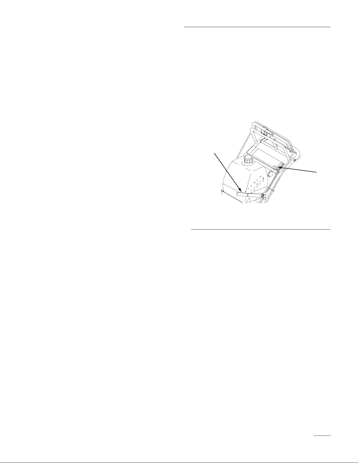
2. Close the fuel shut–off valve in fuel line
(Fig. 41).
3. Squeeze the ends of the hose clamp together and
slide it up the fuel line away from fuel filter
(Fig. 41).
m–3773
37
Page 40

Maintenance
4. Pull the fuel line off the fuel filter (Fig. 41).
Open fuel shut-off valve and allow gasoline to
drain into a gas can or drain pan.
Note: Now is the best time to install a new
fuel filter because the fuel tank is
empty. Refer to Replacing the Fuel
Filter; page 38.
5. Install the fuel line onto the fuel filter. Slide the
hose clamp close to the filter to secure the fuel
line.
3
2
1. Fuel
2.
Fuel filter
shut-of
Figure 41
f valve
1
m–3778
3. Clamp
Fuel
Filter
Service Interval/Specification
Replace the fuel filter after every 200 operating hours
or yearly, whichever occurs first.
Replacing the Fuel Filter
Never install a dirty filter if it is removed from the
fuel line.
1. Disengage the blade control (PTO) and set the
parking brake. Stop engine.
2. Close fuel shut–off valve (Fig. 41).
3. Squeeze the ends of the hose clamps together
and slide them away from the filter (Fig. 42).
4. Remove the filter from the fuel lines.
5. Install a new filter and move the hose clamps
close to the filter.
6. Open fuel shut-off valve at fuel tank (Fig. 41).
38
2
1. Hose
1
clamp
m–3778
Figure 42
2. Filter
Page 41

Maintenance
Replacing
the Wheel Belt
Service Interval/Specification
Check all belts after every 50 operating hours or
monthly, whichever occurs first. Look for dirt, wear,
cracks and signs of overheating.
1. Remove hairpin cotter securing brake rod to
brake arm to relax belt idler tension (Fig. 43).
2. Remove bottom and loosen top bolts of shield to
rotate for belt clearance (Fig. 43).
3. Lift belt past idler and off drive pulley (Fig. 43).
4. Raise wheel off ground enough to allow belt
removal.
Note: Ensure that the mud and grass scraper
is adjusted properly and centered in the
pulley grooves (see page 42). The
pointed part of the scraper should be
centered and as deep in the pulley
groove as possible, without rubbing at
any point.
5. Replace drive belt.
Replacing
the T
raction Belt
1. Stop the engine, set the parking brake and
remove the spark plug wire(s).
2. Raise the rear of the machine and hold with jack
stands.
3. Remove mower belt (Fig. 45).
4. Loosen pivot bolt enough to slide idler pulley in
slot and remove traction belt from the engine and
drive pulleys.
5. Install new belt around engine and drive pulleys
(Fig. 44).
6. Slide idler pulley in engine frame to tension
traction belt (Fig. 44).
7. Install the mower belt (Fig. 45).
8. Check the belt guide under the engine frame for
proper adjustment (Fig. 44). The distance
between the belt guide and mower belt should be
1-3/8” (35mm). Adjust as necessary. The
disengaged belt should not drag or fall off pulley
when guides are properly adjusted.
6. Secure shield with previously removed bolt and
tighten bolts (Fig. 43).
7. Secure brake rod to brake arm with haripin cotter
(Fig. 43).
1
2
3
Figure 43
1. Hairpin
2.
cotter
Brake rod
3. Shield
4.
Drive belt
1. Idler
2.
Belt guide
4
in slot
1
3
2
m-4726
2
Figure 44
3.
1-3/8” (35 mm)
4.
Mower belt
39
Page 42

Maintenance
Replacing
the Mower Belt
1. Disengage the power take off (PTO), set the
parking brake, and turn the ignition key to
“OFF” to stop the engine. Remove the key and
spark plug wire.
2. Remove the knobs and belt cover on mower.
3. Remove idler pulley and then remove worn belt
(Fig. 45).
4. Install new belt.
5. Install idler pulley.
6. Engage PTO and check belt tension. See
Adjusting Mower Belt Tension, page 41.
Note: Proper belt tension is 10–15 lbs. with
the belt deflected a 1/2” (13mm)
halfway between pulleys (Fig. 45).
1
3
4
3
2
1
4
5
6
m–3860
Figure 46
1. 1/16”
2. Bellcrank
3. T
(2mm)–1/8” (3mm)
ransmission output shaft
4.
Hairpin cotter
5.
Clevis pin
6. Clevis
9. Disengage the PTO. If the assist arm does not
contact the front stop on the mower deck
(Fig. 45), readjust the clevis to bring the
bellcrank closer to the transmission output shaft
(Fig. 46).
10. Check the belt guide under the engine frame for
proper adjustment (Fig. 44). The distance
between the belt guide and mower belt should be
1-3/8” (35mm). Adjust as necessary. The
disengaged belt should not drag or fall off pulley
when guides are properly adjusted.
2
Figure 45
1. Idler
2.
pulley
1/2” (13 mm) deflection
here
Assist arm
3.
4.
Front stop
7. Engage PTO lever and check the clearance
between the bellcrank and the transmission
output shaft (Fig. 46). Space should be 1/16”
(2mm)–1/8” (3mm).
8. Remove hairpin cotter and clevis pin from
bellcrank. Rotate clevis clockwise on rod to
increase or counterclockwise to decrease
clearance (Fig. 46).
40
m–4731
Page 43

Maintenance
Adjusting
Mower Belt T
ension
Service Interval/Specification
Check belt tension after the first hour of operation
and at least twice during the first 24 hours of
operation.
IMPORTANT: Belt must be tight enough to not
slip during heavy loads while cutting grass. Over
tensioning will reduce belt and spindle bearing
life.
1. Set the parking brake, and turn the ignition key
to “OFF” to stop the engine. Remove the key
and spark plug wire.
2. Loosen locknut on turnbuckle (Fig. 47).
3. Rotate turnbuckle toward rear of mower to
increase tension on belt. Rotate turnbuckle
toward front of mower to decrease tension on
belt (Fig. 47).
4. If the belt is still loose after making adjustments
to the turnbuckle, reposition the rear idler pulley
to the front hole. The belt guide next to the
pulley must also be moved to the front hole
(Fig. 47).
5. Readjust the turnbuckle.
Adjusting
the Blade Brake
1. Disengage the power take off (PTO), set the
parking brake, and turn the ignition key to
“OFF” to stop the engine. Remove the key and
spark plug wire.
2. If necessary, adjust the spring mounting bolts so
that the blade brake pad rubs against the pulley
edges (Fig. 48).
3. Adjust the nut at the end of the blade brake rod
until there is 1/8” (3mm)–3/16” (5mm) between
the nut and spacer (Fig. 48).
Note: The eyebolt threads on both ends of the
turnbuckle should be engaged a
minimum of 5/16” (8mm).
3
4
5
1. Locknut
2. Turnbuckle
3. Rear
idler pulley
Figure 47
12
4.
Front position for idler
pulley
5.
Belt guide
m–4731
4. Engage the blades. Ensure the blade brake pad
no longer contacts the pulley edges.
3
2
m–47271
Figure 48
1. Spring
2.
mounting bolts
Blade brake pad
3.
1/8” (3mm)–3/16” (5mm)
41
Page 44

Maintenance
Adjusting
Grass\Mud Scraper
1. Loosen the locknut holding scraper to the engine
frame (Fig. 49).
2. Rotate scraper until they align with center of
pulley grooves (Fig. 49).
3. Tighten the locknut (Fig. 49).
Note: The scraper must not contact the pulley
on the sides or bottom of grooves.
Re-adjust if necessary
2
.
3
Replacing
the Grass Deflector
1. Remove the locknut, bolt, spring and spacer
holding deflector to the mounts (Fig. 50).
2. Straighten deflector mounts if they are bent
(Fig. 50).
3. Install new deflector between mounts with
spacer and spring. Hook the front end of the
spring around the front deflector mount. Insert
bolt through spacer and secure with locknut.
Confirm there is downward spring force on
deflector (Fig. 50).
4. Tighten the bolt and locknut until they lightly
contact the pivot brackets (Fig. 50).
IMPORTANT: The grass deflector must be
spring-loaded in the down position. Lift the
deflector up to test that it snaps to the full
down position.
1. Scraper
2. Locknut
1
Figure 49
3. Pulley
m–3776
1. Deflector
2. Bolt
3. Deflector
4
mount
5
6
Figure 50
4. Spring
5. Spacer
6. Locknut
3
2
1
42
Page 45

Maintenance
Wiring
Diagram
J4
J5
WIRE LIST
DESIG. AWG COLOR ROUTE
W1 16 WHITE J2 J4
W2 16 WHITE J2 J3
W3 16 BLUE P1-1 J5
W4 16 BLACK P1-2 J1
W3
W1
P1 PTO
J3
KILL
W2
J2
MAG
W4
J1
GND
1
2
43
Page 46

Maintenance
Cleaning and Storage
1. Disengage the blade control (PTO), set the
parking brake and turn the machine “OFF”.
2. Remove grass clippings, dirt, and grime from the
external parts of the entire machine, especially
the engine. Clean dirt and chaff from the outside
of the engine’s cylinder head fins and blower
housing.
IMPORTANT: You can wash the machine
with mild detergent and water. Do not
pressure wash the machine. A
use of water, especially near the control panel,
and engine.
When done washing, start engine and engage
PTO and run for five minutes. This will dry
machine before storing.
3. Check the brake; refer to Brake, page 36.
4. Service the air cleaner; refer to Air Cleaner,
page 28.
5. Grease the machine; refer to Greasing and
Lubrication, page 35.
6. Change the crankcase oil; refer to Engine Oil,
page 29.
7. Check the tire pressure; refer to Tire Pressure,
page 35.
void excessive
B. Run the engine to distribute conditioned
fuel through the fuel system (5 minutes).
C. Stop the engine, allow it to cool and drain
the fuel tank; refer to Draining Fuel Tank,
page 37.
D. Restart the engine and run it until it stops.
E. Choke or prime the engine.
F. Start and run the engine until it will not
start again. Use the primer, if equipped on
machine, several times to ensure no fuel
remains in primer system.
G. Dispose of fuel properly. Recycle as per
local codes.
IMPORTANT: Do not store
stabilizer/conditioned gasoline over 90 days.
9. Remove the spark plug(s) and check its
condition; refer to Spark Plug, page NO TAG.
With the spark plug(s) removed from the engine,
pour two tablespoons of engine oil into the spark
plug hole. Now use the starter to crank the
engine and distribute the oil inside the cylinder.
Install the spark plug(s). Do not install the wire
on the spark plug(s).
10. Check and tighten all bolts, nuts, and screws.
Repair or replace any part that is damaged or
defective.
8. For storage over 30 days, prepare the traction
unit as follows.
A. Add a petroleum based
stabilizer/conditioner to fuel in the tank.
Follow mixing instructions from stabilizer
manufacturer. (1 oz. per gallon). Do not use
an alcohol based stabilizer (ethanol or
methanol).
Note: A fuel stabilizer/conditioner is most
effective when mixed with fresh
gasoline and used at all times.
44
11. Paint all scratched or bare metal surfaces. Paint
is available from your Authorized Service
Dealer.
12. Store the machine in a clean, dry garage or
storage area. Cover the machine to protect it and
keep it clean.
Page 47

Troubleshooting
g
g
g
PROBLEM
Engine will not start, starts hard, or
fails to keep running.
Engine loses power
.
POSSIBLE CAUSES
1.
Fuel tank is empty
2.
Choke is not ON.
3.
Air cleaner is dirty
4.
Spark plug wire is loose or
disconnected.
5.
Spark plug is pitted, fouled, or
gap is incorrect.
6.
Dirt in fuel filter
7.
Dirt, water
fuel system.
1.
Engine load is excessive.
2.
Air cleaner is dirty
3.
Oil level in crankcase is low
4.
Cooling fins and air passages
under engine blower housing
are plugged.
5.
Spark plug is pitted, fouled, or
gap is incorrect.
, or stale fuel is in
. 1.
. 3.
. 6.
. 2.
2.
4.
5.
7.
1.
. 3.
4.
5.
CORRECTIVE ACTION
Fill fuel tank with gasoline.
Move choke lever to ON.
Clean or replace air cleaner
element.
Install wire on spark plug.
Install new
spark plug.
Replace fuel filter
Contact Authorized Service
Dealer.
Reduce ground speed.
Clean air cleaner element.
Add oil to crankcase.
Remove obstruction from
cooling fins and air passages.
Install new
spark plug.
, correctly gapped
.
, correctly gapped
Engine overheats.
Abnormal vibration.
6. V
ent hole in fuel cap is
plugged.
7.
Dirt in fuel filter
8.
Dirt, water
fuel system.
1.
Engine load is excessive.
2.
Oil level in crankcase is low
3.
Cooling fins and air passages
under engine blower housing
are plugged.
1.
Engine mounting bolts are
loose.
2.
Loose engine pulley
pulley
, or blade pulley
3.
Engine pulley is damaged.
. 7.
, or stale fuel is in
, idler
.
6.
8.
1.
. 2.
3.
1. T
2. T
3.
Clean or replace the fuel cap.
Replace fuel filter
Contact Authorized Service
Dealer.
Reduce ground speed.
Add oil to crankcase.
Remove obstruction from
cooling fins and air passages.
ighten engine mounting
bolts.
ighten the appropriate
pulley.
Contact Authorized Service
Dealer.
.
45
Page 48

Troubleshooting
gg
gg
PROBLEM
Machine does not drive.
Abnormal vibration.
Uneven cutting height.
POSSIBLE CAUSES
1.
Shift lever is in NEUTRAL.
2. T
raction belt is worn, loose or
broken.
3. T
raction belt is of
1.
Cutting blade(s) is/are bent or
unbalanced.
2.
Blade mounting bolt is loose.
3.
Engine mounting bolts are
loose.
4.
Loose engine pulley
pulley
, or blade pulley
5.
Engine pulley is damaged.
6.
Blade spindle bent.
1.
Blade(s) not sharp.
2.
Cutting blade(s) is/are bent.
f pulley
. 3.
, idler
.
CORRECTIVE ACTION
1.
Move shift lever to a drive
gear position.
2.
Change Belt.
Change Belt.
1.
Install new cutting blade(s).
2. T
ighten blade mounting bolt.
3. T
ighten engine mounting
bolts.
4. T
ighten the appropriate
pulley.
5.
Contact Authorized Service
Dealer.
6.
Contact Authorized Service
Dealer.
1.
Sharpen blade(s).
2.
Install new cutting blade(s).
Blades do not rotate.
Blades do not stop when
disengaged.
3.
Mower is not level.
4.
Underside of mower is dirty
5. T
ire pressure is incorrect.
6.
Blade spindle bent.
1.
Drive belt is worn, loose or
broken.
2.
Drive belt is of
3.
Deck belt is worn, loose or
broken.
4.
Deck belt is of
1.
Blade brake is not adjusted
properly.
f pulley
f pulley
3.
. 4.
5.
6.
1.
. 2.
3.
. 4.
1.
Level mower from
side-to-side and front-to-rear.
Clean the underside of the
mower.
Adjust tire pressure.
Contact Authorized Service
Dealer.
Check belt tension.
Install drive belt and check
adjusting shafts and belt
guides for correct position.
Install new deck belt.
Install deck pulley and check
the idler pulley
spring for correct position and
function.
Adjust blade brake.
, idler arm and
46
2.
Belt guide is not set properly
. 2.
Adjust belt guide.
Page 49

Page 50

Page 51

Page 52

LCE
A OneĆYear Limited Warranty
(A TwoĆYear Full Warranty for Residential Use)
What Is Covered B
Th
e T
oro Company promises t
d f
or commercial
use
e i
n m
tiv
apply fro
Product
Al
All Spindles 2 years parts & labor
Engines o
The cos
pays th
radius o
this warranty for Ridin
Maintenanc
S Z-Master Zero Radius Tractors
S ProLin
S Groundsmaster Ridin
S ProLine Hand-held Gas Products
S Backpack Blowers
S Tur
S Debris Managemen
TORO Products use
two-year warranty.
aterials or workmanship
m the date of p
l P
roducts 1 year.
What Products Are Covered B
. . . . . . . . . . . . . . . . .
.
. . . . . . . . . . . . . . . . . .
n the f
ollowing: 2 years.
Out Fron
ProLin
Groundsmaster Ridin
ProLine Hand Held Gas Products
(A
Backpack Blowers
t of p
e t
f a T
f M
t and M
e M
id–siz
E & L
E e
ngines only)
arts an
ransportation cost
ORO ProLin
e E
quipment.
e M
id-siz
aintenanc
How About Residential Use?
How Do You Get Warrant
y This E
, i
nstitutional
urchase:
idMoun
e M
owers
d l
abo
r are i
e S
g P
roducts
e M
owers
g M
e E
quipment
t E
quipment
d f
or residentia
xpres
o r
epai
r a
ny TORO Product
, o
r renta
. The f
ollowin
Warranty Period
3rd yea
. . . . . . . .
t Z
ero Radius Tractors
g M
owers
ncluded
. T
ransportation withi
ervice Deale
owers
, M
idsiz
y This W
l use a
y S
, but t
r i
e M
s W
arranty?
l p
urposes i
g time f
r p
he customer
n a 1
s covere
owers an
arranty?
re covere
ervice?
f d
efec-
rames
arts only
5–mile
d u
nder
d T
urf
d b
y a full
If for any reason you are dissatisfied with a Service Dealer’s
analysis
a referra
contac
,
Yo
tenanc
routin
you
Ther
sion system coverag
above
S Cos
S Any produc
S Repairs necessary du
S Picku
Al
TORO Service Deale
of the d
l t
t u
Wha
u must m
e p
e m
, i
s at you
How Doe
e i
s n
. T
t o
filters
brak
require
dents
th
e f
m p
te
15-mil
l r
epairs covere
efec
t i
n m
o a T
ORO ProLin
s a
t the f
Toro Customer Service Department
811
Bloomington
612–888–880
t M
ust You D
aintain your TORO Produc
rocedures describe
aintenance, whethe
r e
xpense.
What Doe
s Y
our Stat
o o
the
r e
his express warranty does not cover:
f r
egula
, f
uel
, l
ubricants
e a
nd clutc
t o
d r
eplacemen
, o
r l
ack o
uel system
rio
r t
o a
ny perio
p and d
elivery charges fo
e r
adius fro
d b
aterial
ollowin
xpress warranty excep
r m
h a
r p
f p
, o
e S
g a
ddress:
1 L
yndal
e A
, M
1 o
o T
o Kee
d i
r p
s This W
and
e L
aw Relat
e o
n som
e p
aintenance servic
, t
une-u
djustments.
art whic
y this warranty mus
r u
t o
rope
r f
ailur
d of n
m a T
sin
e t
g Toro a
h h
r repai
r m
o i
e to p
ORO ProLin
s o
r w
orkmanshi
ervice Dealer
venu
N 55420–1196
r 8
00–348–2424
p The W
n the o
erforme
arranty Not Cover?
roducts an
p p
arts
as bee
r due to n
aintenance.
mprope
roperly prepar
on-us
r d
pprove
, p
leas
e S
outh
arrant
y I
t b
y followin
perator’s manual
d b
y a d
eale
e T
o This W
t f
or specia
d a
s described
e o
r p
arts, suc
, b
lade sharpening,
n a
ltere
d o
ormal wear
r f
uel, contaminants in
e over t
hre
e m
istances beyon
e S
ervice Dealer.
t be p
erforme
d r
eplacemen
p or i
e feel free t
n Effect?
g the m
r or b
arranty?
l e
r m
isuse
e the f
onths.
f you n
. S
y
mis-
h a
s
, a
cci-
uel sys-
d a
d b
y a
t p
eed
ainuch
d o
arts.
o
r
Should yo
terials or workmanship, contac
produc
Pages of you
source
Service Dealer wil
shi
may b
(copy o
validation.
u f
eel your TORO Product contain
t o
r a
ny TORO ProLin
r t
; l
p o
r recommen
e m
f r
elephon
ook under TORO Commercia
ore convenient
egistration card, sales receipt
l e
d a
ithe
nothe
e d
r a
irectory i
rrange servic
r a
. You m
t the d
e S
ervice Dealer
s a good r
uthorize
ay nee
s a d
ealer who sold yo
l S
ervice Dealers
e at h
d S
ervice Dealer who
d p
, e
tc.
. The Y
eference
is/he
roo
f of p
) f
or warranty
efec
r d
urchase
t i
n m
u t
ellow
. T
ealer-
he
a-
he
oro Compan
l d
amage
tia
Product
expens
ing reasonabl
in
state
quentia
t
o y
This warrant
als
e o
g c
ompletio
s d
l d
ou.
o have o
s c
f providin
o not a
amages
y i
s i
overe
y g
ther rights whic
s not l
n c
onnection with th
d b
y t
his warranty
g s
eriod
s o
f repair
, s
o th
s you s
ubstitut
s u
e a
e p
n o
llow exclusion
ive
iabl
e f
or indirect o
e use o
, i
ncludin
e e
f m
pecifi
quipment o
alfunctio
nder this warranty
s o
bov
h vary from s
f i
ncidenta
e e
xclusio
c l
egal rights
n o
r c
onsequen-
f th
e T
ORO
g any c
r s
r non-us
ervic
e p
. S
ome
l o
r c
onse-
n may not a
, and you m
tat
e t
o s
tate.
ost or
e d
end-
pply
Th
e T
Customers who have purchased TORO products exported from the United States or Canada should contact their TORO DisĆ
tributor (Dealer) to obtain guarantee policies for your country, province, or state. If for any reason you are dissatisfied with
your Distributor's service or have difficulty obtaining guarantee information, contact the TORO importer. If all other remedies
fail, you may contact us at The Toro Company.
Rev
9/30/98
ur-
ay
 Loading...