

Page 1

32in Recycler Kit
for Fixed Deck Mid–Size Mowers
Model No. 30118
Installation Instructions
Loose Parts
Note: Use the chart below to identify parts for assembly.
DESCRIPTION QTY. USE
Form No. 3350-108
Baffle
Bolt, 5/16 x 5/8 inch
Flange nut, 5/16 inch
Blocker plate
Bolt, 3/8 x 1 inch
Flange nut, 3/8 inch
Bolt, 1/4 x 3/4 inch
Flange nut, 1/4 inch
Cover plate
Bolt, 3/8 x 3/4 inch
Flange nut, 3/8 inch
Kicker
Bolt, 5/16 x 5/8 inch
Flange nut, 5/16 inch
Recycler blade 2 Replace standard blades on mower
Preparing the Mower
1. Remove belt cover from top of mower .
1
1
6
1
1
1
2
2
1
4
4
2
4
4
Install the Recycler baffle
Install the blocker plate
Install the cover plate
Install the kickers
Note: Replace hardware in top of mower when baffle is
removed for safety and to save for use when using mower
to side discharge.
2. Thoroughly clean underside of the mower. All debris
must be removed to ensure that baffles and kickers will
fit properly against the cutting chamber.
3. Tilt the mower up and support with jack stands to ease
installation of kit.
4. Flip up discharge chute and remove the discharge baffle
near discharge opening (Fig. 1).
2004 by The Toro Company
8111 Lyndale Avenue South
Bloomington, MN 55420-1196
Contact us at www.Toro.com
All Rights Reserved
Printed in the USA
Page 2
Warning
2
Open holes in the mower exposes you and others to
thrown debris. Debris thrown out of holes in the
mower can cause injury.
• Never operate mower without hardware
mounted in all holes in mower.
• Install hardware in mounting holes when
mulching baffle is removed.
1
Figure 1
1. Discharge baffle
m–3923
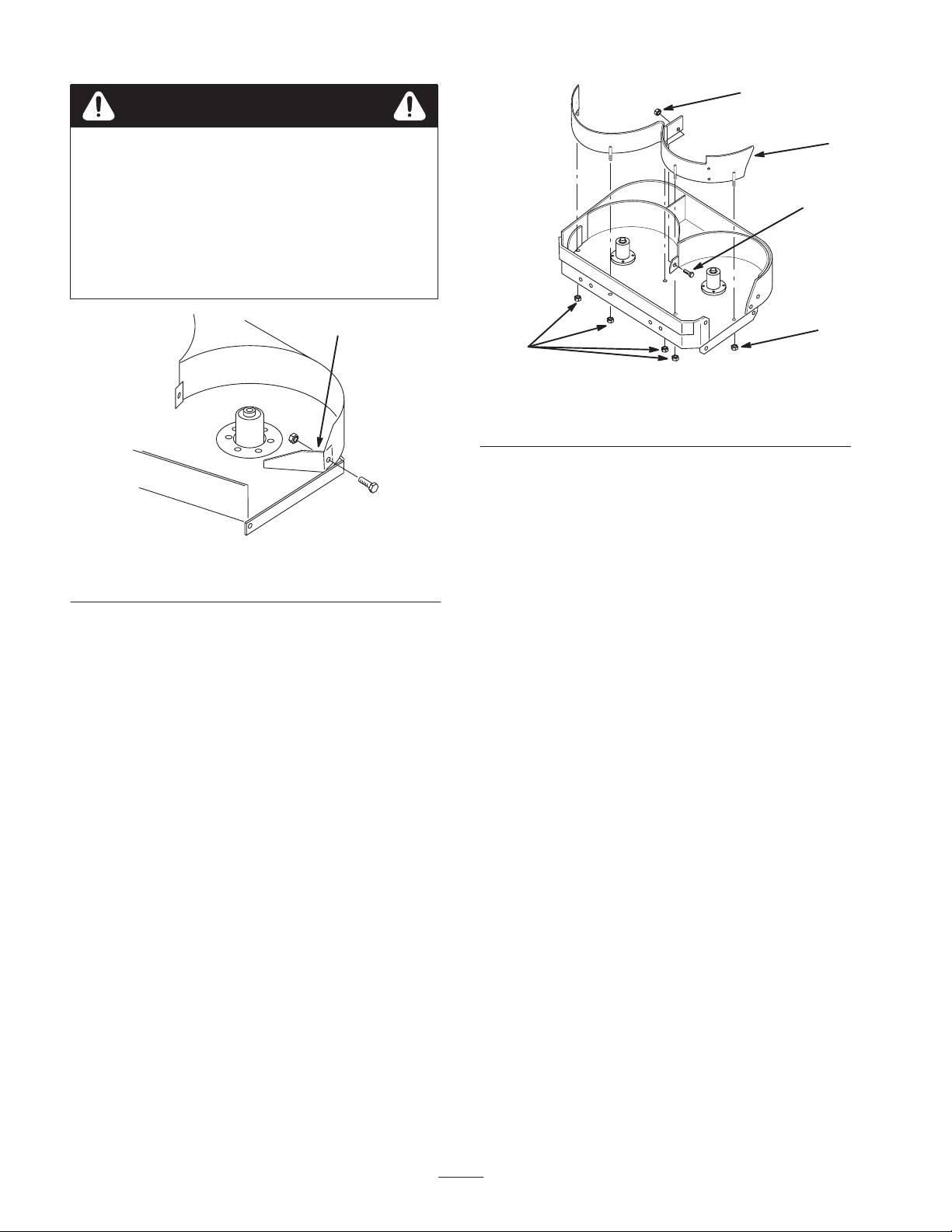
3
2
2
1. Baffle
2. Flange nut 5/16 inch
Figure 2
3. Bolt, 5/16 x 5/8 inch
(16 mm)
m–3924
Installing the Blocker Plate
1. Place the blocker plate inside cutting chamber between
the front and baffle.
2. Remove the existing caster mounting hardware where
the blocker plate is to be installed.
1
Installing the Front Baffle
1. Remove the 5 carriage bolts (5/16 x 5/8 inch) and
locknuts (3/8 inch) from the holes where the baffles will
be installed (Fig. 2).
Note: Save the previously removed hardware for use when
using mower to side discharge.
2. Place the baffle inside cutting chamber with studs
through the top.
3. Secure the studs to top of mower with 5 flange nuts
(5/16 inch) and to the back baffle with a bolt (5/16 x
5/8 inch) and a flange nut (5/16 inch) (Fig. 2).
3. Secure the blocker plate to the front of mower with a
bolt (3/8 x 1 inch) and a flange nut (3/8 inch) (Fig. 2).
4. Secure the blocker to the front baffle with 2 bolts (1/4 x
5/8 inch) and 2 flange nuts (1/4 inch) (Fig. 2).
2
Page 3

3
4
Installing the Kickers
1. Measure from the spindle center lines, and locate
1
kickers as shown (Fig. 5). Position one kicker 7/16 inch
(11 mm) off to the right of the right spindle and one
kicker 1-7/8 inch (48 mm) off to the left of the left
spindle (Fig. 5).
2. Holding kickers tight against baffle, mark, center punch
and drill 2 holes (11/32 inch) holes for each kicker
(Fig. 5).
1 (right) 2 (left)
2
5
m–3925
Figure 3
1. Blocker plate
2. Bolt, 3/8 x 5/8 inch
3. Flange nut, 3/8 inch
4. Bolt, 1/4 x 5/8 inch
5. Flange nut, 1/4 inch
Installing the Cover Plate
1. Position the cover plate over the side discharge opening.
2. Secure the cover plate to the mower with 4 bolts (3/8 x
3/4 inch) and 4 flange nuts (3/8 inch) (Fig. 4).
1
3
3
3
m–3914
Figure 5
1. 7/16 inch (11 mm)
2. 1-7/8 inch (48 mm)
3. Mark, center punch and
drill 11/32 inch (9 mm)
holes
3. Place the kickers inside the mower over drilled holes
and install each kicker with 2 bolts (5/16 x 5/8 inch)
through from the bottom of the mower, and 2 flange
nuts (5/16 inch) (Fig. 6).
.
3
2
Figure 4
1. Discharge cover plate
2. Bolt 3/8-16 x 3/4 inch
(19 mm)
3. Flange nut, 3/8 inch
3. Tighten all mounting hardware securely.
m–3926
Figure 6
1. Kicker
2. Bolt, 5/16 x 5/8 inch
3. Flange nut, 5/16 inch
4. Tighten all mounting hardware securely.
3
2
1
m–3927
Page 4

Installing the Recycler Blades
Warning
Removing Baffles for Side
Discharge Cutting
1. Thoroughly clean the mower.
A blade is sharp. Contact with sharp blade can
cause serious personal injury.
• Wear gloves or wrap sharp edges of the blade
with a rag.
1. Remove the standard blades (Fig. 7). Refer to
Operator’s Manual.
2. Place the blade onto the bolt, over cone washer. Select
proper number of spacer(s) for height-of-cut and slide
bolt into spindle (Fig. 7).
Important The sail (curved part of the blade) must be
pointing toward the inside of the mower to ensure proper
cutting.
3. Install remaining spacer(s) for proper height-of-cut and
secure with thin washer and nut (Fig. 7).
4. Torque the blade bolt to 75–80 ft. lb. (101–108 Nm).
5. Rotate the blades to ensure that there is at least 1/8 inch
(3 mm) clearance between the blades and baffles.
6. Remove jack stands and lower mower.
2. Tilt the mower up and support with jack stands to ease
removal of kit.
3. Remove the mounting hardware from the baffle,
blocker plate, kickers and discharge cover plate.
Note: Save the hardware for use when installing the baffle.
Warning
Open holes in the mower exposes you and others to
thrown debris. Debris thrown out of holes in the
mower can cause injury.
• Never operate mower without hardware
mounted in all holes in mower.
• Install hardware in mounting holes when
mulching baffle is removed.
4. Install previously removed discharge baffle
5. Install previously removed standard blades.
6. Remove jack stands and lower mower.
7
4
1
2
1. High-lift lade
2. Blade bolt
3. Cone washer
4. Spacer
6
4
3
5
m–3779
Figure 7
5. Tube
6. Thin washer
7. Nut
4
 Loading...