

Page 1

JLO L/RM252 ENGINE MECHANICS HANDBOOK
Table of Contents – Page 1 of 1
PREFACE
TECHNICAL DATA
OPERATING - AND MAINTENANCE INSTRUCTIONS
A. BEFORE STARTING
B. SERVICE AND MAINTENANCE
C. ADDITIONAL INSTRUCTIONS
D. GENERAL TROUBLE SHOOTING
ASSEMBLY GROUP 1
RECOIL STARTER
ASSEMBLY GROUP 2
FLYWHEEL, IGNITION SYSTEMS
ASSEMBLY GROUP 3
TIMING PROCEDURE
ASSEMBLY GROUP 4
SPEED CONTROL - RM 252 FLYBALL GOVERNOR
ADJUSTMENT INSTRUCTIONS - MECHANICAL
SPEED CONTROL--L 252 TOP SPEED LIMITER
ASSEMBLY GROUP 5
CARBURETTOR, CARBURETTOR DATA
ASSEMBLY GROUP 6
PISTON, CYLINDER
ASSEMBLY GROUP 7
CRANKCASE,CRANKSHAFT-RM 252
CRANKCASE , CRANKSHAFT - L252
TABLE OF SPECIFICATION
Page 2
MECHANIC'S HANDBOOK
L/RM
252
Page 3
MOTOR
SERVICE
1
U
7
5
1
4
4
Page 4
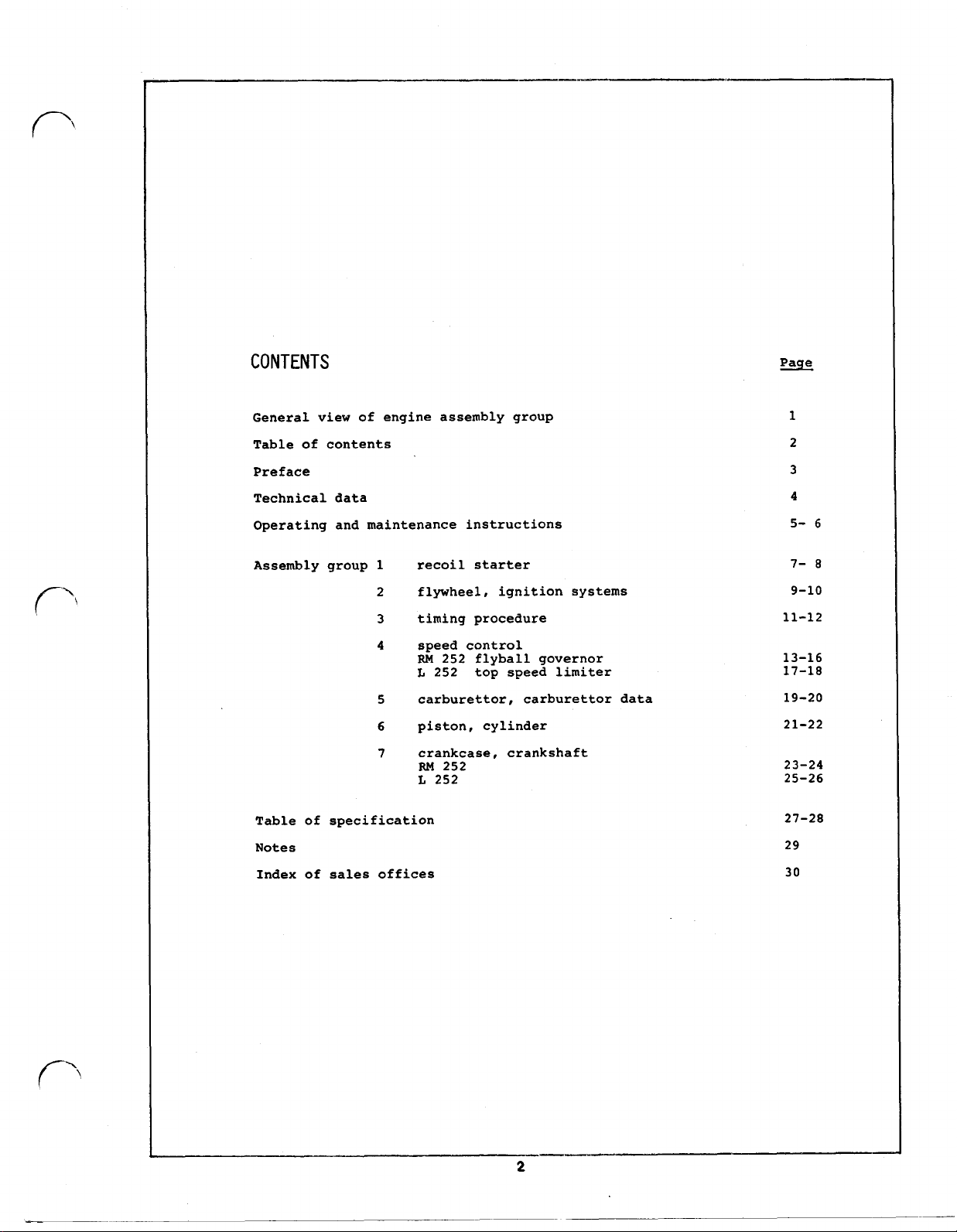
CONTENTS
Page
General vic
of
Table
Preface
Technical data
Operating and maintenance instructions
Assembly group 1 recoil starter
contents
2 flywheel, ignition systems
3
4 speed control
timing procedure
RM
L
5 carburettor, carburettor data
6 piston, cylinder
7 crankcase, crankshaft
L
of
Table
Notes
Index of sales offices
specification
embl of engine ass
252 flyball governor
252 top speed limiter
RM
252
252
1
2
3
4
5-
6
7-
8
9-10
11-12
13-16
17-18
19-20
21-22
23-24
25-26
27-28
29
30
Page 5
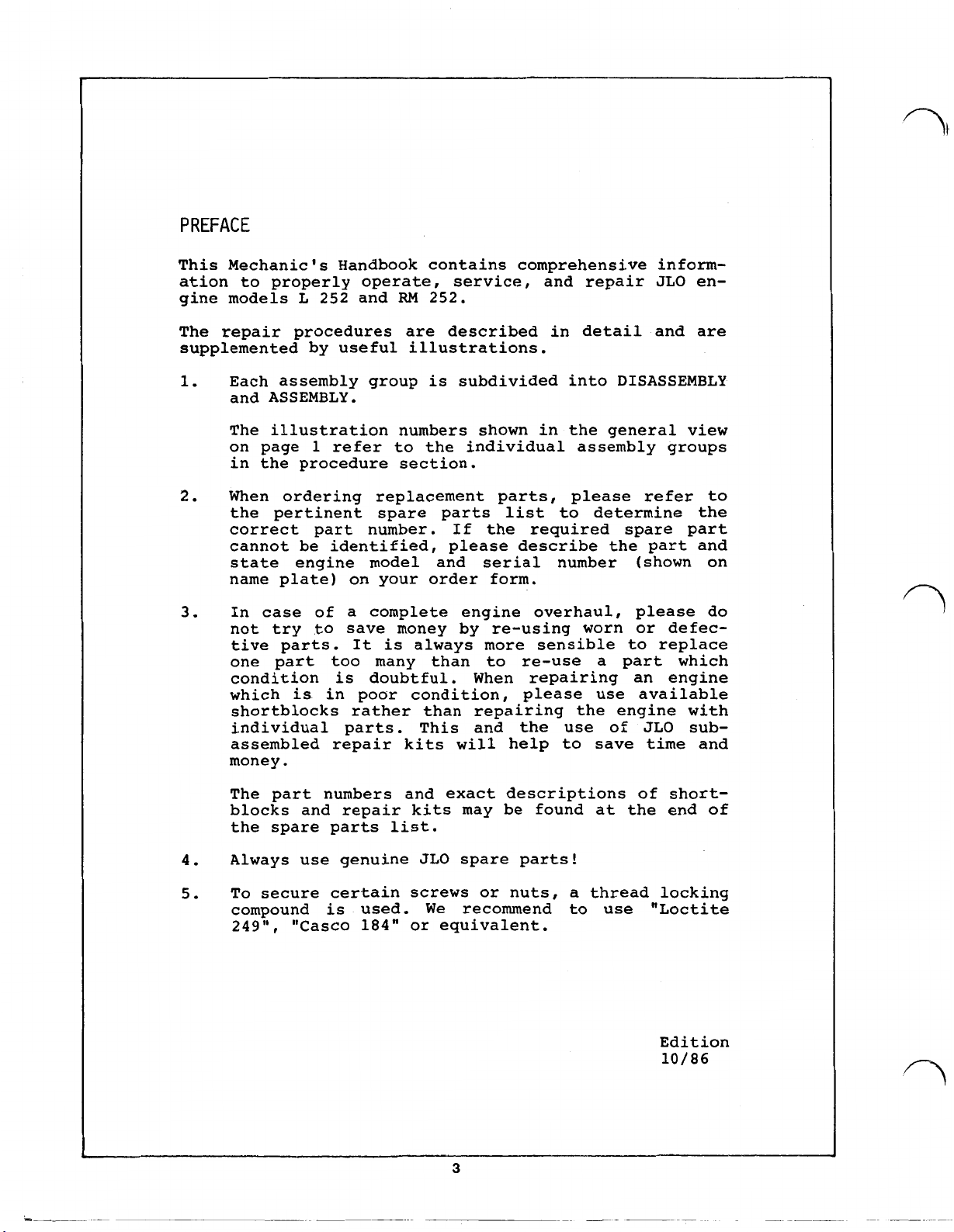
This Mechanic's Handbook contains comprehensive information to properly operate, service, and repair JLO en-
L
252
and
RM
gine models
252.
The repair procedures are described in detail and are
supplemented by useful illustrations.
1.
2.
3.
Each assembly group
is
subdivided into DISASSEMBLY
and ASSEMBLY.
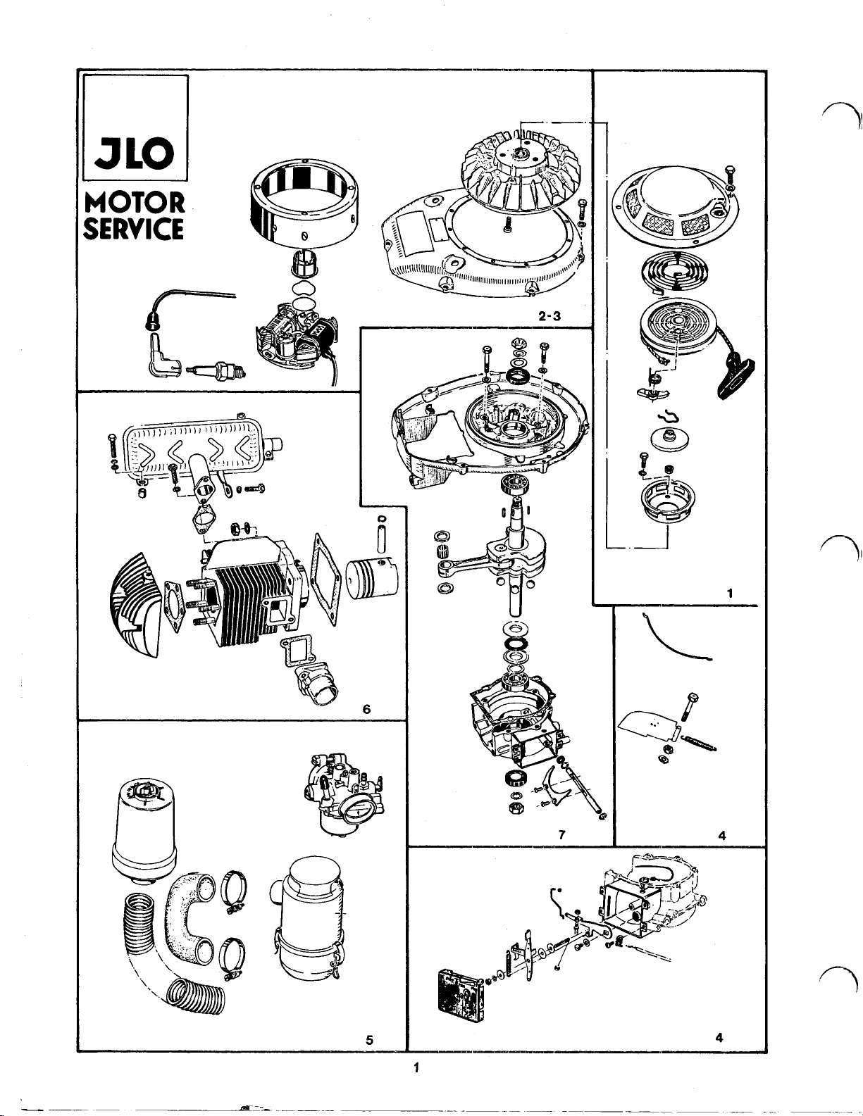
The illustration numbers shown in the general view
on page
1
refer to the individual assembly groups
in the procedure section.
When ordering replacement parts, please refer to
the pertinent spare parts list to determine the
correct part number. If the required spare part
cannot be identified, please describe the part and
state engine model and serial number (shown on
name plate) on your order form.
In case of a complete engine overhaul, please do
not try to save money by re-using worn or defec-
tive parts. It is always more sensible to replace
one part too many than to re-use a part which
condition is doubtful. When repairing an engine
is
which
in poor condition, please use available
shortblocks rather than repairing the engine with
individual parts. This and the use of JLO subassembled repair kits will help to save time and
money.
of
The part numbers and exact descriptions
shortblocks and repair kits may be found at the end of
the spare parts list.
4.
5.
Always use genuine JLO spare parts!
To secure certain screws or nuts, a thread locking
compound
249",
"Casco
used.
184"
We
recommend to use "Loctite
or equivalent.
is
Edition
10/86
3
Page 6
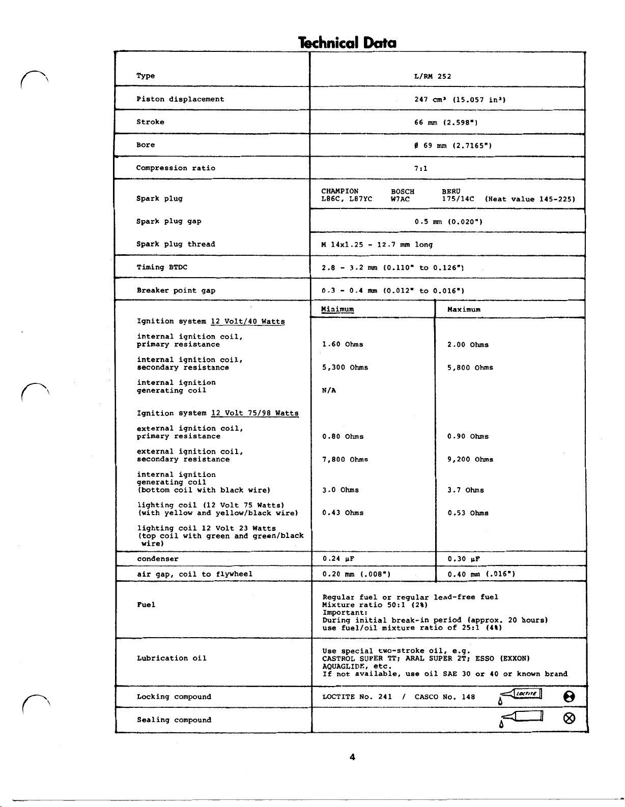
Type
L/RM 252
Piston displacement
Stroke
Bore
Compression ratio
Spark plug
Spark plug gap
Spark plug thread
Timing BTDC
Breaker point gap
Ignition system 12 Volt/40 Watts
internal ignition coil,
primary
internal ignition coil,
secondary resistance
internal ignition
generating coil
resistance
247
cm³
(15.057 in³)
66
mm
(2.598")
69
nun
(2.7165")
7:1
CHAMPION
L86C, L87YC
M 14x1.25 - 12.7
2.8 - 3.2
0.3 - 0.4
Minimum Maximum
1.60
Ohms
5,300
Ohms
N/A
BOSCH BERU
W7AC 175/14C (Heat value 145-225)
0.5
mm
(0.020")
mm
long
mm
(0.110" to 0.126")
mm
(0.012" to 0.016")
2
.00
ohms
5,800
Ohms
Ignition system 12 Volt 75/98 Watts
external ignition coil,
primary resistance
external ignition coil,
secondary resistance
internal ignition
generating coil
(bottom coil with black wire) 3.0
lighting coil (12 Volt 75 Watts)
(with yellow and yellow/black wire)
lighting coil 12 Volt 23 Watts
(top coil with green and green/black
wire)
condenser
Fuel
Lubrication oil
Locking compound
0.80
7,800
0.43
0.24
0.20
Regular
Mixture ratio
Important:
During initial break-in period (approx. 20 hours)
use fuel/oil mixture ratio of 25:1
Use special two-stroke oil, e.g.
CASTROL SUPER
AQUAGLIDE, etc.
If not available, use oil SAE 30 or 40 or known brand
LOCTITE No. 241 / CASCO No. 148
Ohms
Ohms
Ohms
Ohms
mm
(.008")
fuel or regular lead-free fuel
(2%)
TT;
ARAL SUPER 2T; ESSO (EXXON)
0
.90
9,200
3.7
ohms
0.53
0.30
0.40
ohms
Ohms
Ohms
mm
(.016") air gap, coil to flywheel
(4%)
Sealing compound
b
4
Page 7
Operating-
A.
Before starting
1.
Refueling
Mixture ratio -please
2.
Engine
Check that cooling fins
heating
3.
Air
Be sure that
Oil
Check oil level, refill
4.
Starting
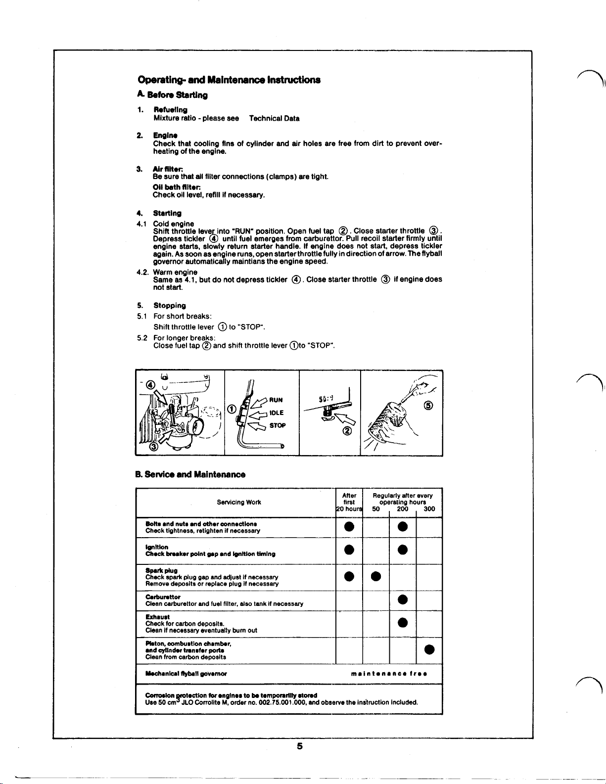
4.1
Cold engine
Shift throttle lever into
Depress tickler until fuel emerges from carburettor. Pull recoil starter firmly until
engine starts. slowly return starter handle.
again.
governor automatically maintains the engine speed.
4.2.
Warm engine
Same as
not start.
5.
Stopping
5.1
For
Shift throttle lever
5.2
For longer breaks:
Close fuel tap shift throttle lever
and
Maintenance
see
of
the engine.
filter:
bath
all
filter connections (clamps) are tight.
filter:
As
soon as engine runs, open starter throttle fully in direction of arrow. The
4.1,
but do not depress tickler Close starter throttle
of
if
necessary.
'RUN'
Instructions
Technical Data
cylinder and
position. Open fuel tap Close starter throttle
air
holes are free from dirt to prevent over-
If
engine does not start. depress tickler
short breaks:
"STOP".
"STOP".
if
engine does
flyball
B.
Service
Bolts
Check tightness, retighten if necessary
Ignition
Chock
Spark
Check
Remove deposits or replace plug if necessary
Carburetor
Clean carburettor and fuel
Exhaust
Check
Clean if necessary eventually burn out
Piston, combustion chamber,
and cylinder transfer
Clean from carbon deposits
Mechanical
Corrosion
Use
and
and nuts and
breaker
plug
spark
plug
for
carbon deposits.
flyball
50
cm
JLO
Maintenance
Servicing
Work
other
connections
point gap and
gap
governor maintanance
Corroilte
ignition
and adjust if necessary
filter.
also
ports
for
engines
to
be
M,
order no.
timing
tank if necessary
temporarilly
002.75.001.000,
stored
and observe the instruction included.
5
free
Page 8
C
Additional Instructions
1.
Alr
Intake
filter
Keep dust and dirt out of the engine to avoid premature wear.
sty or
dirty
1.1 Paper element filter: Blow out with air against normal direction
very dirty cartridges.
1.2 Oil bath filter:
Change oil (filling qty. 160- 180 cm³ SAE
D.
General Trouble Shooting
environment, the air filter may have to be cleaned in short intervals.
30)
and observe indicated mark!
If
engineisoperated lndu-
of
airflow. Replace wet or
Possible cause:
1.
Englne does not start
1.1 Fuel tap closed
1.2
No
fuel in tank
1.3 Clogged fuel filter in carburettor or
tap
of
fuel tank or fuel hose
1.4 Engine over-choked (flooded)
1.5 Spark plug fouled
1.6 Main carburettor jet plugged
1.7 Dirty carburettor
1.8 Spark plug cap
loose or damaged
2
Engine runs unevenly
2.1 See 1.5-1.8 See above
2.2 Loose spark plug Tighten spark plug
3.
Engine does
3.1 See 1.5 and 1.6 See above
3.2 Choke still closed Open choke
3.3
Dirt in fuel filter and hoses Clean
3.4 Dirty aircleaner or main jet Clean
3.5 Exhaust and/or exhaust port in
cylinder clogged Remove carbon deposits
3.6 Bowdencable misadjustment Adjust properly
or
ignition cable
not
produce
or
ceases to
full
Remedy:
Open fuel tap
Fill
tank with clean, fresh fuel/oil mixture
Clean filter, blow out dirt
Close fuel tap. Start engine several times.
Remove spark plug, clean and dry it. If
necessary, crank engine without spark plug.
Clean and regap spark plug. Replace if
necessary. (Plug type see A Technical Data)
Clean
Clean
Retighten, resp. replace
fire
power
All
other failures which
Improper repairing can cause damages and
CAUTION
Carriers
ignition system.
of
cardiac pacemakers should avoid touching current carrying parts
always
require
be
taken
Use genuine
partial
care
or
complete dismantling
of
by an approved service shop.
JLO
spare
lifts
the
parts only.
claim
6
of
the engine should
to guarantee.
of
the
Page 9
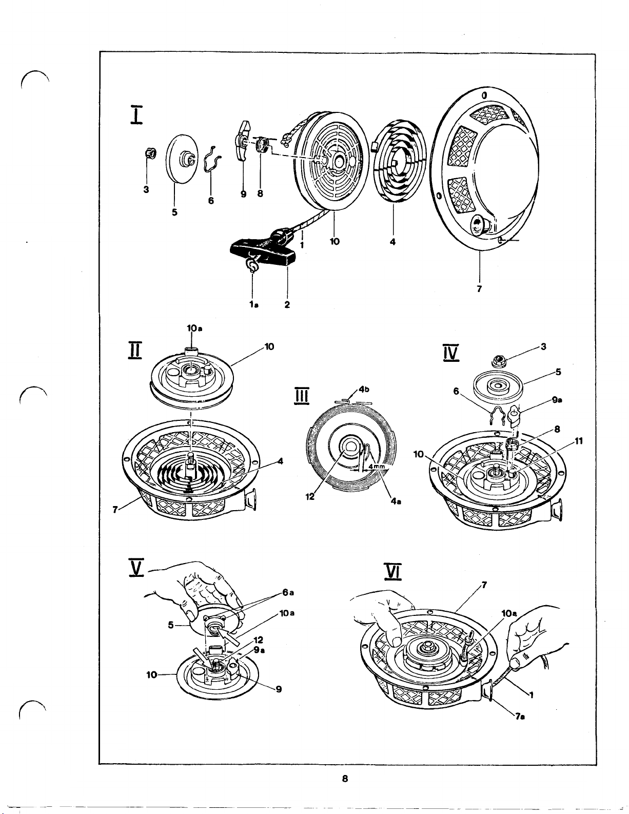
Assembly
group1
RECO I L
DISASSEMBLY
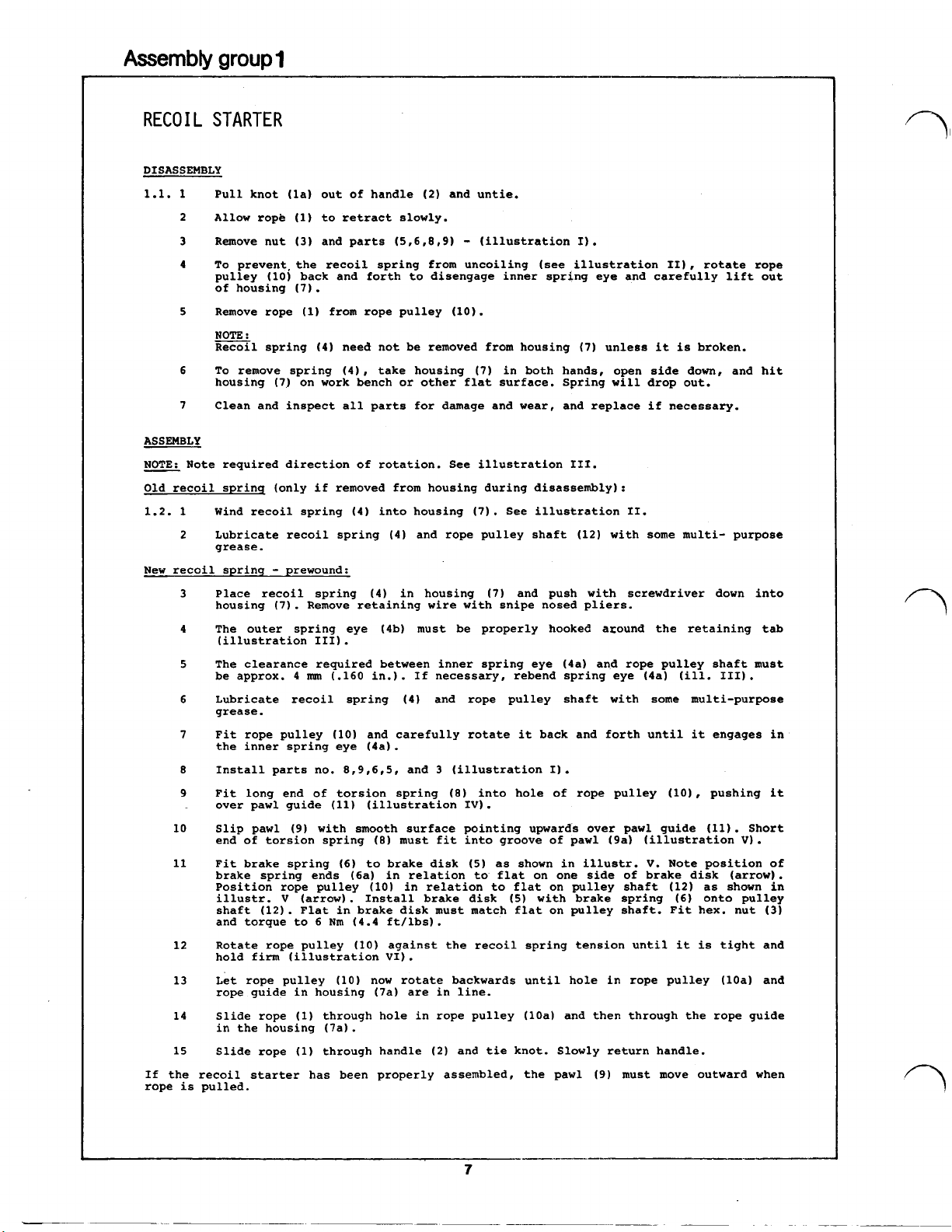
1.1. 1 Pull knot (1a) out
ASSEMBLY
NOTE: Note required direction of rotation. See illustration III.
Old recoil spring (only if removed from housing during disassembly):
1.2. 1 Wind recoil spring (4) into housing
New recoil spring - prewound:
If the recoil starter has been properly assembled, the pawl
rope is pulled.
STARTER
of
handle
2
Allow rope
3
Remove nut
4
To
prevent. the recoil spring from uncoiling (see illustration II), rotate rope
pulley (10) back and forth to disengage inner spring eye and carefully lift out
of housing
5
Remove rope (1) from rope pulley (10).
NOTE
:
Recoil
6
To
remove spring (4), take housing
housing
7
Clean and inspect all parts for damage and wear, and replace if necessary.
2
Lubricate recoil spring (4) and rope pulley shaft (12) with some multi- purpose
grease.
Place recoil spring (4) in housing
3
housing (7). Remove retaining wire with snipe nosed pliers.
4
The outer spring eye (4b) must be properly hooked around the retaining tab
(illustration III).
The clearance required between inner spring eye (4a) and rope pulley shaft must
5
be approx. 4
Lubricate recoil spring (4) and rope pulley shaft with some multi-purpose
6
grease.
7
Fit rope pulley (10) and carefully rotate it back and forth until it engages in
the inner spring eye (4a).
8
Install parts no. 8,9,6,5, and 3 (illustration I).
9
Fit long end of torsion spring
over pawl guide (11) (illustration IV).
10
Slip pawl
end of torsion spring
11
Fit brake spring
brake spring ends (6a) in relation to flat on one side
Position rope pulley (10) in relation to flat on pulley shaft (12) as shown in
illustr. V (arrow). Install brake disk
shaft (12). Flat in brake disk must match flat on pulley shaft. Fit hex. nut
and torque to 6 Nm (4.4 ft/lbs).
Rotate rope pulley (10) against the recoil spring tension until it is tight and
12
hold firm (illustration VI).
Let rope pulley
13
rope guide in housing (7a) are in line.
Slide rope (1) through hole in rope pulley (10a) and then through the rope guide
14
in the housing (7a).
Slide rope (1) through handle
15
(1)
to retract slowly.
(3)
and parts
(7).
spring (4) need not be removed from housing
(7)
on work bench or other flat surface. Spring will drop out.
mm
(.160 in.). If necessary, rebend spring eye (4a) (ill. III).
(9)
with smooth surface pointing upwards over pawl guide (11). Short
(8)
(6)
to brake disk
(10)
now rotate backwards until hole in rope pulley (10a) and
(2)
and untie.
(5,6,8,9)
must fit into groove of pawl (9a) (illustration
-
(illustration I).
(7)
unless it is broken.
(7)
in both hands, open side down, and hit
(7).
See illustration II.
(7)
and push with screwdriver down into
(8)
into hole of rope pulley (10), pushing it
(5)
as shown in illustr.
(5)
with brake spring
(2)
and tie knot. Slowly return handle.
(9)
V.
Note position
of
brake disk (arrow).
(6)
must move outward when
V).
of
onto pulley
(3)
Page 10
5
I
6
I
le
7
2
11
10
6a
Oa
Page 11

Assembly
group
2
FLYWHEEL,
Special JLO Tools
Flywheel puller (11) 444.31.843.100
DISASSEMBLY
2.1.
1
2
3
4
5
6
7
8
ASSEMBLY
2.2. 1
2
3
4
5
6
7
8
9
10
11
IGNITION
Remove screws (1) with lock washer (2) carrier (3).
Remove screws
Remove hex. nut (7). spring washer
To
pull off flywheel (10) use puller (II). Unless magnetic flywheel (25) is defective
it need not
fanwheel remove hex. nuts (24), lock washers (23). and screws (22).
NOTE
:
Holes
in magnetic flywheel are unevenly spaced,
in one position.
Remove key (12), cam (13), spring (14), washer (15) , and pin (16).
Note or mark position of armature plate in crankcase. Remove screws (17), lock
washers (18), and flat washers (19). Remove armature plate (20).
Check coils, condenser, and breaker points, and replace if necessary. (For specifica-
tions, please refer to page
If engine is
Slightly lubricate wires with silicon spray and feed them-through their corresponding
grommets.
Install armature plate (20) and fasten with screws (17), lock washers (18), and flat
washers (19).
If engine is equipped with a 12 Volt, 75/23 Watts ignition system, the green and
green/black lead of the 23 Watts coil must be connected.
(See wiring diagram on page 12).
Place thrust washer (15) and spring (14) on crankshaft. Install cam locating pin (16)
in its groove (16a).
NOTE
:
Cam
(13)
If the engine is to run counterclockwise, you must use the groove with the arrow
pointing to the clockwise rotation. (Groove "L" as shown in illustr.
II and III).
Position cam on crankshaft. Be sure pin (16) is properly seated in cam groove.
To properly set ignition timing, please refer to timing section on page 11/12.
Degrease crankshaft taper and mating taper in fanwheel (10).
Place key (12) in keyway on crankshaft. Inspect inside of magnetic flywheel to
be sure no foreign parts cling to magnets.
NOTE
:
Fanwheel (10) has 2 keyways. If the engine is to run counterclockwise, you must
use the keyway with the arrow pointing to the clockwise rotation. (Keyway
shown in illustr. II)
Place fanwheel (10) on crankshaft. Be sure key (12) is located in proper keyway.
To
prevent water from getting into the ignition area through the unused keyway,
apply sealing compound (10a) to face
washer
Nm. (65-75 ft/lbs).
Install fan cover (6) with lock washers
Install carrier (3) with lock washers (2) and screws (1).
(9),
SYSTEMS
(4)
with lock washer (5) and fan cover (6).
be
removed from fanwheel (10). To separate magnetic flywheel (25) from
so
equipped, remove external ignition coil
has 2 grooves on the inner periphery. Each groove is marked with an arrow.
.
spring washer
(8),
and flat washer (9).
so
flywheel will only fit in fanwheel
4).
(21).
of
(8),
and hex. nut (7). Torque hex. nut (7) to 90-100
fanwheel hub as shown. Install flat
(5)
and screws (4).
"L"
as
9
Page 12

25
15
cam
14
13
clockwise
erclockwise
\
rotation
Page 13

Assembly
group
3
PROCEDURE
Special
Timing gauge
Timing light (2) 000.15.330.000
TIMING DATA:
JLO
Tools
(1)
441.31.875.000
-
Engine Model
L/RM
252
-
Timing BTDC .110 - .126 inches (2.8 - 3.2
Breaker Point Gap .012 - .016 inches
Spark plug gap .020 inches (0.5
PREPARATIONS
3.1.
1 Screw timing gauge (1) into spark plug hole of cylinder head.
2
Connect one lead of timing light to engine ground, the other lead to
the disconnected wire of the ignition system.
3
Bring piston into top dead center position.
BREAKER
IGNITION TIMING
NOTE
Breaker points must be adjusted to proper gap PRIOR to timing the engine.
POINT GAP
4
Check breaker point gap with feeler gauge.
5 To adjust breaker point gap, loosen retaining screw
specified gap by moving fixed part of point set (5).
6
Tighten retaining screw (4), and re-check gap.
:
7
Note reading
position.
of
timing gauge with the piston still in top dead center
(0.3
-
mm)
0.4
mm)
mm)
(4)
and ad just to
8
9
10
11
Turn crankshaft approx.
of rotation (away from TDC), then slowly turn flywheel towards TDC
until timing light (2) changes from dim to bright
device changes loudness (timing point).
Note reading on timing gauge. The difference between the 2 readings
(step
of timing gauge, before TDC.
To
plate in required direction.
NOTE
Rotating the armature plate in the direction of engine rotation will
retard the timing, while rotating the armature plate in the opposite
direction of engine rotation will advance the timing. Never attempt to
advance or retard the timing by changing the breaker point gap.
Tighten armature plate retaining screws (7), and re-check timing repeating the procedure described in steps
NOTE
If timing settings cannot be obtained, breaker points
If breaker points are corroded or otherwise contaminated, engine may
tend to backfire. Clean!
If breaker points are badly pitted, they must be replaced.
Replacement armature plates (12 Volts,
lighting coil. If coil is not used, it may either be removed prior to
installing the plate
coil.
7
and
9)
is the timing in inches
change timing, loosen armature plate retaining screws (7) and rotate
:
:
90°
in opposite direction of normal direction
or
buzzer of timing
or
mm,
depending on calibration
7,
8,
and
9.
must
be replaced.
40
Watts) may be equipped with a
or
the 2 yellow leads may be cut off right at the
11
Page 14

generator
ignition
generating
8
armature plate
(11)
1
9
2
netted
switch)
I
to
kill
yellow/black.
leads when
the
coil
utilized.
I!
!
is
Page 15

Assembly
group
SPEED CONTROL
RM
252
4
FLYBALL GOVERNOR
Special
Vibration tachometer 000.15.300.100
DISASSEMBLY
4.1. 1 Remove nut
ASSEMBLY
4.2. 1 If engine stop contact (10) has been removed, re-install by
JLO
Tools
(21),
washer (18), and cover (17).
2 Disconnect throttle cable noting the hole position for re-assem-
bly. Remove clip
3
When removing lever (2) note into which of the 5 holes the
governor spring (3) is hooked. To remove lever (2)
nut (16), spring washer (15), steel washers (14), and plastic
washer (12). Note sequence. Remove screw
(7)
.
Slide governor lever
4
Engine stop contact (10) need not be removed unless it is to be
replaced.
snapping it back into the bore in governor housing. Be sure
recess in flange clears boss
2
If stud (13) is loose or has been removed, re-install in
crankcase with thread locking compound.
3 Install governor lever
(6).
4
Install lever (2) with washers (14,12), spring washer (15), and
new lock nut (16)
to section "governor adjustment procedure".
(9)
from linkage and unhook linkage (1).
,
remove lock
(6)
(8)
out
of
governor housing.
of
crankcase.
(8)
with spring washer (7) and screw
.
For precise lock nut tightness please refer
and spring washer
5 Install governor spring (3) in appropriate hole of levers 2 and
8.
6
Install governor linkage (1) and secure with new clip
7
Connect throttle cable.
8
Cover (17) with washer (18) and nut (21) should be installed
after governor has been properly adjusted. Please refer to
corresponding section in this manual.
:
NOTE
Bolts (22)
governor shaft (23). (Observe reach of screw!)
When bolts (22) are inserted correctly, lever must move freely
(ill. II).
too
long
or
inserted incorrectly might
13
(9).
jam
the
Page 16

b
Page 17
Assembly
group
4
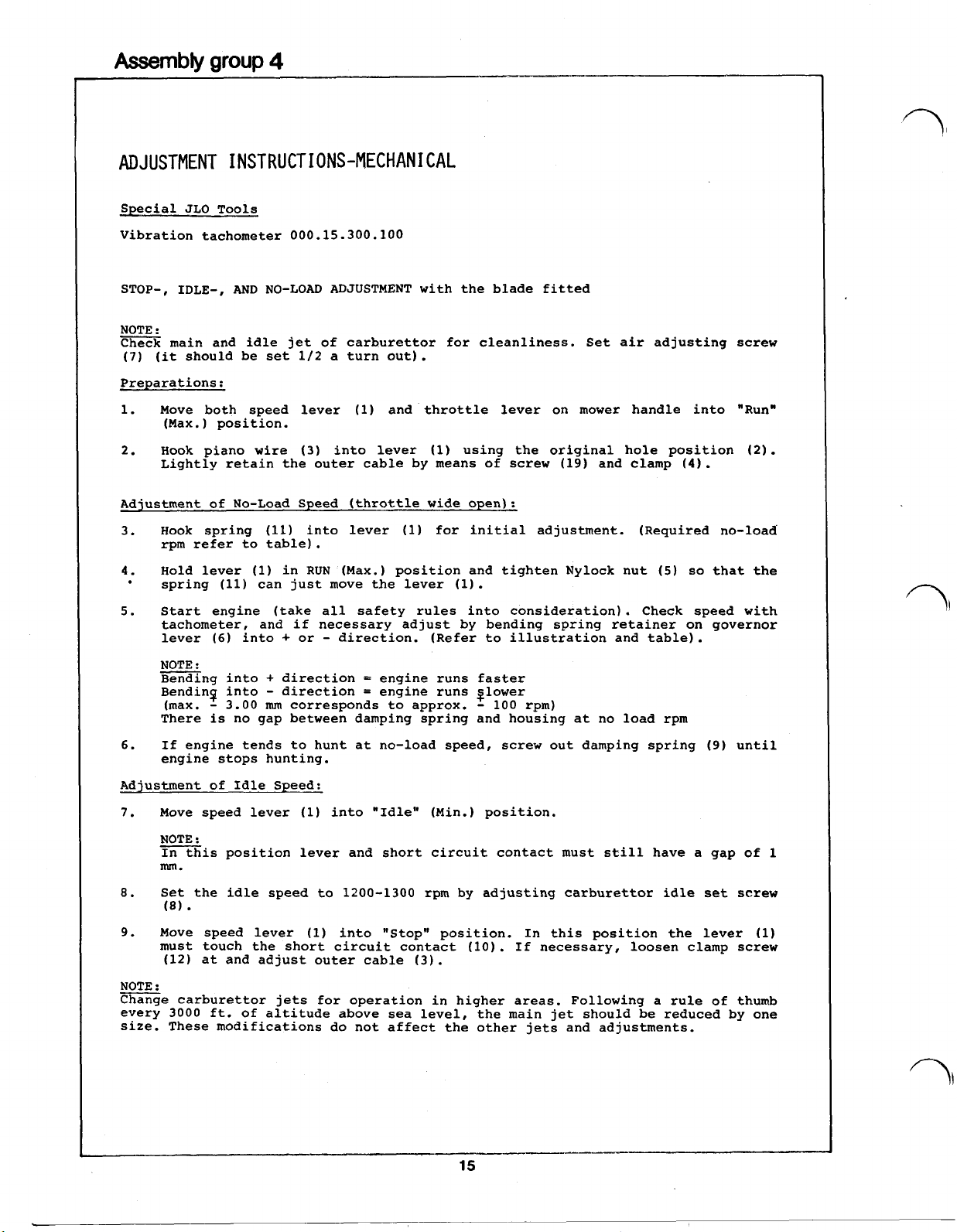
ADJUSTMENT INSTRUCTIONS-MECHANICAL
Special JLO Tools
Vibration tachometer 000.15.300.100
STOP-, IDLE-, AND NO-LOAD ADJUSTMENT with the blade fitted
NOTE
:
Check main and idle jet of carburettor for cleanliness. Set air adjusting screw
(7)
(it should be set 1/2 a turn out).
Preparations:
1. Move both speed lever (1) and throttle lever on mower handle into "Run"
(Max.) position.
2. Hook piano wire
Lightly retain the outer cable by means of screw (19) and clamp
Adjustment of No-Load Speed (throttle wide open):
3.
Hook spring (11) into lever (1) for initial adjustment. (Required no-load
rpm refer to table).
4.
Hold lever (1) in RUN (Max.) position and tighten Nylock nut
spring (11) can just move the lever (1).
5.
Start engine (take all safety rules into consideration). Check speed with
tachometer, and if necessary adjust by bending spring retainer on governor
lever
NOTE
Bending into + direction = engine runs faster
Bending into
(max.
There is no gap between damping spring and housing at no load rpm
6.
If engine tends to hunt at no-load speed, screw out damping spring (9) until
engine stops hunting.
Adjustment
7.
Move speed lever (1) into "Idle" (Min.) position.
NOTE
In this position lever and short circuit contact must still have a gap
(6)
:
-
3.00
of
Idle Speed:
:
into + or - direction. (Refer to illustration and table).
(3)
into lever (1) using the original hole position
-
direction = engine runs glower
mm
corresponds to approx. - 100 rpm)
(4).
(5)
so
that the
(2).
of
1
mm.
8.
Set the idle speed to 1200-1300 rpm by adjusting carburettor idle set screw
(8).
9. Move speed lever (1) into "Stop" position. In this position the lever (1)
must touch the short circuit contact (10). If necessary, loosen clamp screw
(12) at and adjust outer cable (3).
NOTE
:
Change carburettor jets for operation in higher areas. Following a rule
every
size. These modifications do not affect the other jets and adjustments.
3000
ft. of altitude above sea level, the main jet should be reduced
of
thumb
by
one
Page 18

(
/
I
+
higher no-load rpm
-
lower
"
"
No-load adjustment
at
by spring positioning
bore
A
approx. 2750 rpm
B
C
D
E
precise adjustment by bending tongue
max 3.0
mm
correspond with approx. 100 rpm
speed lever
2900
"
3050
3200
"
3400
"
at
wire
wire
lever
1.5
cover, outer
B(C)
6
e
mm
carburettor survey
16
ref.
to
spare parts
list
Page 19

Assembly
group
SPEED CONTROL
L
252
TOP SPEED LIMITER
4
Special
Tachometer
DISASSEMBLY
4.3.
ASSEMBLY
NOTE
Carefully inspect all air vane governor parts for excessive wear or damage.
Replace if necessary. It is particularly important that the governor spring is
not over- stretched or damaged at the spring ends.
4.4. 1 Connect air vane rod
JLO
Tools
-
Vibration Type 000.15.300.100
1
Remove carburettor from intake manifold and disconnect air vane rod
from butterfly lever
:
NOTE
The
butterfly
spindle. When removing the lever, note its original position
(see ill. IV)
2
Carefully unhook spring
3
Loosen hex. nut
4 Remove hex. nut
:
air vane
provided on cylinder (see illustr. I). Do not apply any lubricant to
air vane/spindle!
(5)
,
(2)
lever
(2)
.
(7)
and remove screw
(9)
,
star washer
fit hex. nut
(1)
(see illustr. III and IV).
is positioned by 2 flats on the butterfly
(3)
from lever (4) and airvane
(6)
.
Disconnect air vane rod
(10),
to air vane
(7)
and lock washer
and adjusting lever
(5).
Fit hex. screw
(8)
(5).
(1)
(4).
(6)
,
and install in boss
through
(1)
.
2
Tighten hex. nut
screw (spindle)
3 Connect other end of air vane rod
butterfly spindle. Install carburettor on intake manifold.
NOTE
:
With the air vane in position
tor must be in the fully open position (throttle wide open).
4 Install adjusting lever
5
Carefully hook spring (3) into both holes
as shown in illustr. II.
SPEED ADJUSTMENT
6
Start the engine, observing safety regulations.
7
Loosen hex, nut
lever, and rotate lever to obtain desired engine speed.
:
NOTE
A
=
Higher spring tension = higher speed
=
lower spring tension = lower speed
B
8
When desired speed has been obtained, tighten hex. nut
re-check engine speed with tachometer.
(7)
(6)
with only a little axial play.
(9)
,
insert small punch or drill into hole provided in
so
that air vane moves freely radially on hex.
(1)
"C",
the butterfly valve in the carburet-
(4)
with star washer
to lever
(10)
of
air vane
(2)
of carburettor
and hex. nut
(5)
and lever
(9)
securely and
(9).
(4)
Page 20

I
18
Page 21

Assembly
group
5
CARBURETTOR, CARBURETTOR DATA
DISASSEMBLY
5.1. 1
ASSEMBLY
5.2. 1
Remove air filter from carburettor (1). For filter maintenance please rever to instructions on page 5/6.
2
Close fuel shut-off valve on tank and remove fuel line from carburettor. Remove clip
(2),
governor rod (3), loosen screw (4), remove carburettor (1) from intake manifold.
3
Remove fuel line connection (36), gasket (35), idle jet (5), gasket
ment screw (18), and spring (19).
4
Remove mainjet carrier (7), gasket
5
Remove float by pulling
Remove float needle (14) with spring (15). Remove mixturizer (17).
Check butterfly shaft
6
fly shaft
(24), and foam seal
Butterfly spindle
washer (34) have been removed.
7
Choke shaft assembly (30,31,32) need normally not be removed. In case replacement is
required, note position of detent ball (37) and spring (38).
NOTE
Clean
blow-dry. Inspect all parts for damage and wear, and replace if necessary. Take into
consideration the repair kits mentioned in the preface and at the end of the spare
parts list.
If choke shaft assembly (30,31,32) has been removed, re-install, observing that
cut-out in choke plate points downward and detent ball (37) and spring (38) are in
place.
2
Insert butterfly spindle
screws (27).
NOTE
Butterfly is slightly oval and contour-ground on periphery. For proper position please
see illustr. (I)
3
Install screw (33) and lock washer (34). Fit foam seal (25), washer (24), and and
secure shaft with retainer (23) and screw
4
Install connection (36) with new gasket (35). Install mixturizer (17).
5
Check condition of float (14). and replace if necessary.
NOTE
The float needle seat (16) is pressed-in, and therefore not replaceable.
6
Connect float needle (14) to float (13) via hair pin spring
in carburettor. Fit hinge pin (12).
Float Adjustment
Turn carburettor upside down. Let float (13) close float needle (14) by its own
weight.
of float must be parallel with carburettor housing. If adjustment is required, carefully bend float hinge until parallel. (See illustr.)
7
Install mainjet (10) into mainjet carrier (7), replace gasket
float bowl (9) to carburettor.
NOTE
The float (13) should be in parallel with the surface of the housing. If not, bend the
float hinge accordingly. The float should only touch the float needle (14) slightly
when it is being placed in position. Take care that the elasticity will not be strained too much. The float needle is spring supported!
8
Install idle jet (5) with new gasket
9
Install air adjustment screw (18) with spring (19). Turn screw (18) clockwise until it
bottoms out, (do not force screw
adjustment screw half a turn open).
10
Fit carburettor to engine, tighten screw (4), connect governor linkage (3)
and secure with new clip
NOTE
Dot re-use clip
(28),
remove screw (20), lever
(28)
:
carburettor body and all components in clean fuel or other suitable solvent and
:
.
:
DO
NOT APPLY PRESSURE. Float must move freely on hinge pin (12). Bottom side
:
:
or
pushing float hinge pin (12) out of carburettor housing.
(28)
and choke shaft (31) for excessive wear. To remove butter-
(25).
Remove butterfly retaining screws (27) and butterfly (29).
may be pulled out of carburettor body after screw (33) and lock
(28)
in carburettor body, fit butterfly (29) and secure with
(2).
(2).
(6).
air adjust-
(8),
float bowl (9), and gasket (11).
(21),
screw
(22),
shaft retainer (23), washer
(22).
Mount lever
(6).
(18)
into its seat), then back up half a turn. (Air
(21)
with screw (20).
(15),
as shown and install
(8)
and (11), and fasten
to
lever,
19
Page 22

A Idle set screw
B
Idle jet
C
Air adjustment screw
D
Main jet
Float needle
spring loaded
7
8A
DRC
30S
...
Page 23

Assembly
group
6
PISTON, CYLINDER
DISASSEMBLY
1
6.1.
Loosen nuts (1) and remove spring washers (2)
and gasket (4) . Remove bolt (18) , spring washer (17) , and air
guide (16), if these parts are mounted.
2
Loosen cylinder base nuts
pull off cylinder (7). Discard gasket (8).
3
Remove circlips
(11).
4
Remove thrust washer (12) and needle bearing (13).
:
NOTE
Piston and cylinder ought to be replaced if the max. play between
piston shirt and cylinder wall exceeds
specs., page 27). All ports on the cylinder wall must be beveled,
if the cylinder is re- machined.
,
cylinder head
(5)
and remove spring washers (6), and
(9).
Push or tap out wrist pin, and remove piston
0.35
mm
(see table
(3)
,
of
ASSEMBLY
6.2.
1
2
8
9
10
NOTE
:
Clean sealing surfaces of cylinder and crankcase.
Place new cylinder base gasket (8) on crankcase.
When installing piston (11) the arrow stamped on piston crown must
point towards the exhaust port. (Piston may be installed either
ways if no arrow is shown).
of
Insert needle bearing (13) in eyelet
Install piston (11) and thrust washers (12) with wrist pin (10)
and secure by circlips (9)
Slip a wooden piston support (14) under the piston (11), and
rotate crankshaft until piston rests on support.
Slightly lubricate cylinder liner and piston.
Position piston rings around pegs in ring grooves and compress
rings with ring compressor
ring compressor (15) and piston support (14).
Torque cylinder (7) with nuts
32.4 ft/lbs (44.0 Nm).
Place a new cylinder head gasket (4).
Torque cylinder head
16.2 ft/lbs (22.0 Nm).
.
(15).
(3)
with nuts (1) and spring washers (2) to
Install cylinder
(5)
connecting rod.
(7)
and remove
and spring washers (6) to
1
1
Insert air guide (16) with slotted hole to notched pin (19) in
cylinder head (3) and fasten it with bolt (18) and spring washer
(17) on cylinder (7a)
.
Page 24

A
please
see
I
I
n
:I’
Page 25

Assembly
group
7
CRANKCASE, CRANKSHAFT-RM
Special JLO Tools
Puller 444.31.807.000 (10)
Pair of half shells
Retaining ring
DISASSEMBLY
7.1. 1
ASSEMBLY
7.2. 1
Loosen bolts (3) and remove spring washers (4).
2
Pull crankcase pto side (2) off crankshaft (5). Slide fit of ball bearing (8) and
crankcase (5) allows disassembly without heating up. Discard gasket (22).
3
Remove washer (7) and complete thrust bearing assembly (11) from the crankshaft
(5).
4
Heat crankcase half starter side (1) to approx. 100°C (212°F).
5
Lift crankcase assembly (1),
gently tap crankshaft with plastic hammer out of the crankcase. Remove shim(s) (10)
and seal (19).
6
To remove ball bearing (9) from crankshaft
7
Loosen Loctited screws (17) and remove governor fork (18).
Pull governor shaft (16) out of case (2). Remove washers (15) and knock out small
8
oil seal (14).
9
Heat housing pto side (2) to approx. 100°C (212°F), and tap out ball bearing (8).
10
Remove seal (19) (illustr. I).
Slightly lubricate new oil seals (19). Insert seals with oil seal installation tool
into both crankcase halves (1+2). Sealing lips facing' the inside
2
Place heat shield over oil seal (19) and heat crankcase pto side (2) to approx.
100°C (212°F). Use ball bearing driver and place ball bearing (8) into crankcase.
3
Slightly lubricate governor shaft (16). and fit thrust washers (15) into crankcase
(2) (illustr. I).
4
Use locking compound when tightening screws (17) and fit governor fork (18) on
governor shaft (16). (illustr. II).
5
Knock oil seal (14) into its position. Use slip cone
(illustr. V).
6
Warm ball bearing (9) to approx.
(starter side) by ball bearing driver. (Drive only on
7
Fit governor balls (13) into bores of pto crankweb.
Mount three piece thrust bearing (11). (see illustr. III).
8
9
Mount shim (7) with recess facing towards crankweb.
10
Insert sub-assembled crankshaft
placed slide fitted on crankshaft.
11
Lightly grease new gasket (22) with general purpose grease, and place in position
on crankcase (2).
12
Limit axial play of crankshaft (5) by using shims (10), thickness 0.2
(illustr. IV)
Measuring plane for depth gauge: upper ball bearing edge to crankcase sealing face
with gasket (22) in place (illustr. IV). Any difference between measured result and
required measure (30.1 - 30.2
(10). Thickness of shims 0.2
Place heat shield over oil seal (19), Heat crankcase starter side (1) to approx.
13
100°C (212°F), and mount it (1) on crankcase half, pto side (2).
NOTE:
14
Ensure both crankcase halves (1+2) are properly aligned and install screws (3) with
spring washers (4) fingertight.
Re-check mounting surface for cylinder. Cut off overhanging gasket part (22).
15
Tighten screws of crankcase (3).
16
After mounting cylinder (see description on page 21) tighten crankcase bolts (3).
Torque 90-100 Nm (66.4-73.7 ft/lbs).
17
Turn crankshaft (6) by hand to ensure free moving. If crankshaft will not turn
freely, tap each end of crankshaft lightly with a plastic hammer.
444.31.072.000 (10)
444.31.071.100 (10)
Remove balls (13).
.
Make sure that seals (19) will not be damaged. (Use approximate slip cone).
252
so
that pto shaft end is clear of the work bench, and
(5)
mm/
1.185-1.189 in.) has to be compensated with shims
mm
(.008 in.) (See table
(5)
use bearing puller assembly (12).
of
the crankcase.
(20),
and driver (21)
80°C
(175°F) and drive it on the crankshaft
into crankcase pto side (2) (Ball bearing is
inner
bearing race).
on
page 24).
mm
(.008 in.)
Page 26

I
19
11
5
21
18
(10)
Axial play
0.1
0.1
0.2
000.40.490.960 48
of
crankshaft Measurement
to
0.4
to
0.4
to
0.4
24
b
x
60 x 0.2
2 29.7
1
0
above
above
DIN
29.9
30.1
988
to
to
to
e
a
29.9
30.1
30.2.
Page 27

Assembly
group
7
CRANKCASE, CRANKSHAFT
Special JLO Tools
Puller
Pair of half shells
Retaining ring
DISASSEMBLY
7.3.
1
Loosen screw
2
To
separate crankcase halves
(100°C).
Lift housing that pto shaft end hangs free and carefully tap
crankshaft with plastic hammer out of crankcase.
Discard gasket
Pry or knock out oil seals
To remove ball bearings
puller assembly
ASSEMBLY
7.4.
Slightly lubricate new oil seals. Knock seals with oil seal
1
installation tool into both crankcase halves
must point into crank chamber (ill.
2
Heat ball bearings
crankshaft by a ball bearing driver (ill.
NOTE
:
Ball bearing must be driven on inner bearing race.
444.31.807.000 (10)
444.31.072.000 (10)
444.31.071.100 (10)
(3)
and remove spring washers
(7).
(6)
(10)
(8)
(ill.
(8)
II).
to approx.
(1+2),
(see ill.
from crankshaft
heat them to approx.
I).
III).
175°F
(80°C) and drive them on
IV).
(4).
(1+2)
(5)
use bearing
.
Sealing lips
212°F
Place heat shield over oil seal
3
to
212°F
firmly in place.
NOTE
Make sure that seals
cone)
Lightly grease new gasket
place in position on crankcase
Heat crankcase half
described under item
that both crankcase halves
screws
Re-check mounting surface €or cylinder. Cut off overhanging
gasket
19)
cross-tiahten crankcase screws
Turn crankshaft
crankshaft will not turn freely, tap each end of crankshaft
lightly with a plastic hammer.
(100°C) and install crankshaft
:
(6)
are not damaged (Use appropriate slip
.
(1)
to
3
and mount on crankcase half
(3)
with spring washers
(7).
After mounting the cylinder (see description on page
(5)
by hand to ensure freedom of rotation. If
(1+2)
(6)
and heat crankcase half
(5)
in crankcase. Press
(7)
with general purpose grease and
(2).
212°F
(4)
(100°C) in same manner as
(2).
are properly aligned and install
fingertight.
(3).
(2)
Ensure
Page 28

e
26
Page 29
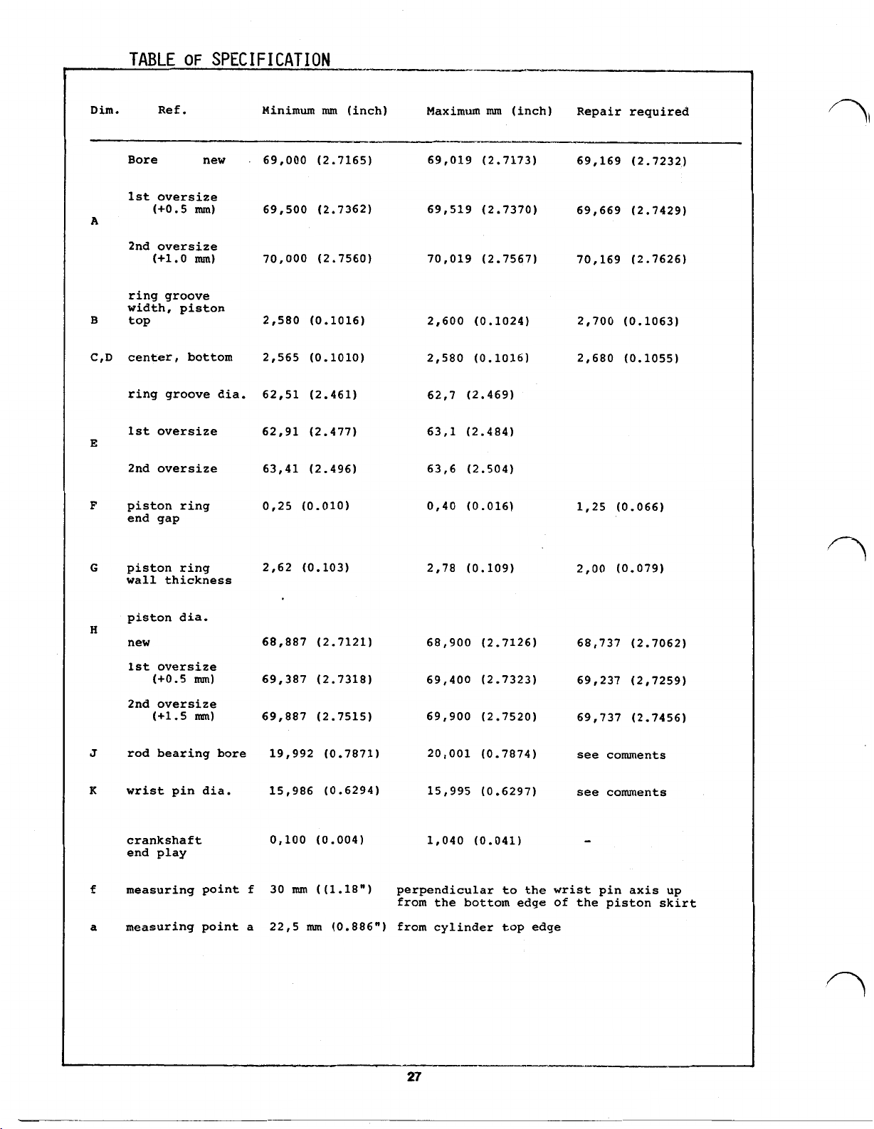
TABLE
OF
SPEC
IF
I
ON
Dim. Ref. Minimum
Bore new
1st
oversize
(+0.5
A
mm)
69,000 (2.7165)
69,500 (2.7362 69,519 (2.7370)
2nd oversize
(+1.0
mm)
70,000
ring groove
width, piston
B
top
center, bottom
C.D
ring groove dia.
1st
E
oversize
2nd oversize
F
piston ring
2,580 (0.1016)
2,565 (0.1010)
62,51 (2.461)
62,91 (2.477)
63,41 (2.496)
0,25 (0.010)
end gap
mm
(inch) Maximum
69,019 (2.7173)
(2.7560 70,019 (2.7567)
2,600
2,580
62,7
63,1
63,6 (2.504)
0,40 (0.016)
mm
(inch) Repair required
(0.1024)
(0.1016)
(2.469)
(2.484)
69,169 (2.7232)
69,669 (2.7429)
70,169 (2.7626)
2,700 (0.1063)
2,680 (0.1055)
1,25 (0.066)
G
piston ring
wall thickness
piston dia.
H
new
1st oversize
(+0.5
2nd oversize
(+1.5
J
rod bearing bore
K
wrist pin dia.
crankshaft
end play
f
measuring point
a
measuring point a
mm)
mm)
2,62 (0.103)
68,887
69,387
69,887
19,992 (0.7871)
15,986 (0.6294)
0,100 (0.004) 1,040 (0.041)
f
30
(2.7121)
(2.7318)
(2.7515)
mm
((1.18")
2,78 (0.109) 2,00 (0.079)
68,900 (2.7126)
69,400 (2.7323)
69,900 (2.7520)
20,001 (0.7874)
15,995 (0.6297)
perpendicular to the wrist pin axis up
from the bottom edge
22,5
mm
(0.886")
from cylinder top edge
68,737 (2.7062)
69,237 (2,7259)
69,737 (2.7456)
see comments
see comments
of
the piston skirt
27
Page 30

NOTE
:
Piston and cylinder ought to be replaced if the max. play between
piston skirt and cylinder wall exceeds
typ, the piston ring end play should not exceed 0.10 to
0.35
mm.
Depending on engine
0.12
mm.
COMMENTS
1.
:
Piston rings:
All three piston rings have to be replaced if piston ring end
gap exceeds the max. dimension stated in table item
end gap has to be measured in the bore of a new cylinder.
2.
Connection rod/wrist pin:
The stressed surfaces of wrist pin and connecting rod turn in a
needle bearing,
so
that the play between these surfaces cannot
easily be measured. If the wrist pin has seized or has changed
colour excessively but rod surface seems to be still undamaged,
replace the wrist pin and needle bearing.
If the bearing surface of rod eye (wrist pin rolling surface)
has seized or has excessively changed colour, the complete
crankshaft ought to be replaced.
"F".
Ring
Page 31

Telefax
1620
Pinneberg
041 01/21 40
2
Telex
0
41 01 69 12
189 113
Pinneberg
fin
PRODUCTS
COMPANY
der
 Loading...