

Page 1
Form No. 3358-281 Rev A
Tru Trak® Sulky
For Floating Deck Mid-Size Mowers
Model No. 30110 —Serial No. 220000001 and Up
Register your product at www.Toro.com Original Instructions (EN)
Page 2
Introduction
R ead this infor mation carefully to lear n ho w to operate
and maintain y our product properly and to a v oid injur y
and product damag e . Y ou are responsible for operating
the product properly and safely .
T his man ual uses 2 other w ords to highlight
infor mation. Impor tant calls attention to special
mec hanical infor mation and Note emphasizes g eneral
infor mation w or th y of special attention.
Contents
Y ou ma y contact T oro directly at www .T oro .com for
product and accessor y infor mation, help finding a
dealer , or to register y our product.
W henev er y ou need ser vice , g en uine T oro par ts , or
additional infor mation, contact an A uthorized Ser vice
Dealer or T oro Customer Ser vice and ha v e the model
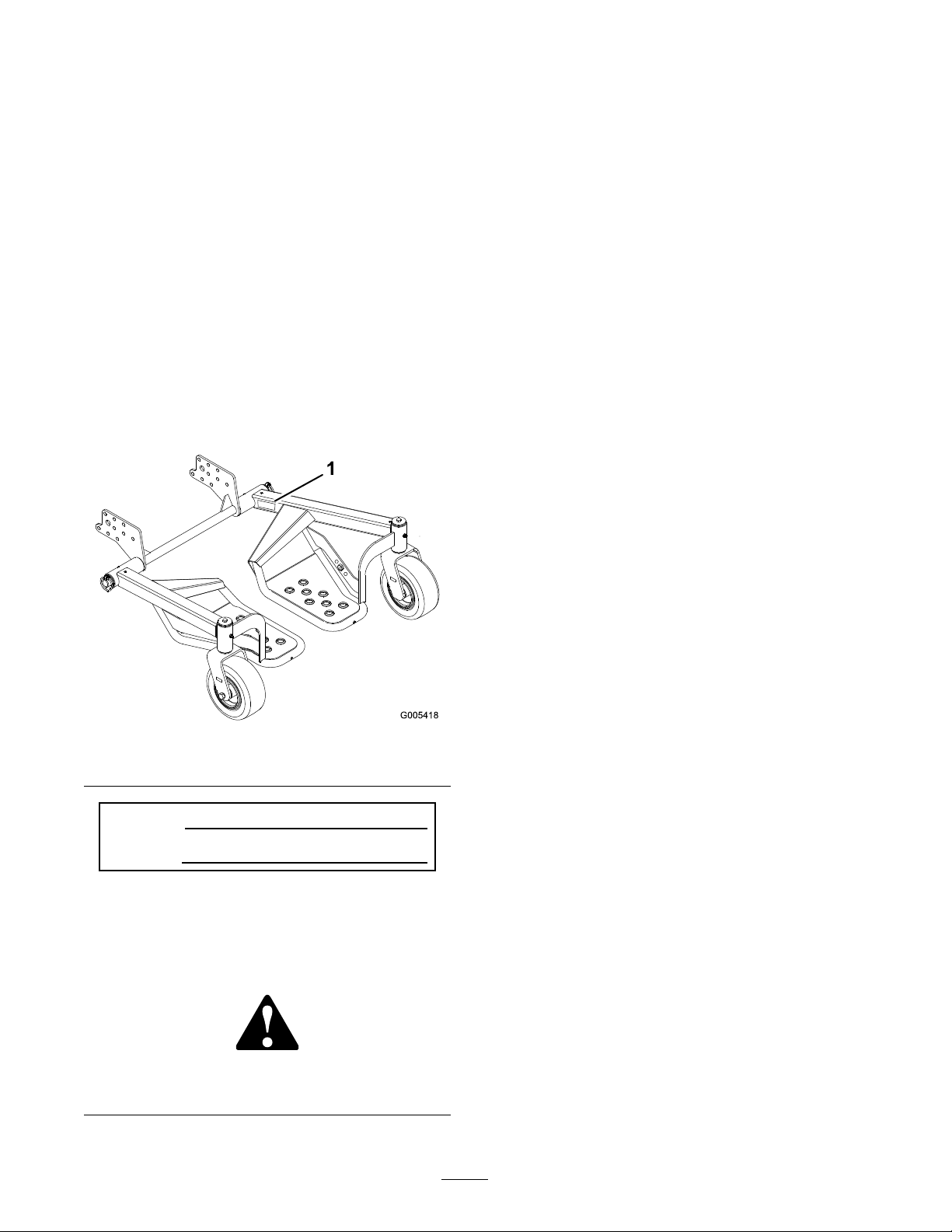
and serial n umbers of y our product ready . Figure 1
identifies the location of the model and serial n umbers
on the product. W rite the n umbers in the space
pro vided.
Figure 1
1. Model and serial number location
Introduction . . . . . . . . . . . . . . . . . . . . . . . . . . . . . . . . . . . . . . . . . . . . . . . . . . . . . . . . . 2
Safety . . . . . . . . . . . . . . . . . . . . . . . . . . . . . . . . . . . . . . . . . . . . . . . . . . . . . . . . . . . . . . . . . . 3
Safe Operating Practices . . . . . . . . . . . . . . . . . . . . . . . . . . . . . . . . . . 3
Setup . . . . . . . . . . . . . . . . . . . . . . . . . . . . . . . . . . . . . . . . . . . . . . . . . . . . . . . . . . . . . . . . . . . 4
1 Installing the Axle on a Hy draulic
Dri v e Mo w er with Standard T -Bar
Handles . . . . . . . . . . . . . . . . . . . . . . . . . . . . . . . . . . . . . . . . . . 5
2 Installing the Axle on a Hy draulic Dri v e
Mo w er with T2 T -Bar Handles . . . . . . . . . . . 6
3 Installing the Axle on Gear Dri v e
Mo w ers with Pistol Grip or T -Bar
Handles . . . . . . . . . . . . . . . . . . . . . . . . . . . . . . . . . . . . . . . . . . 7
4 Installing the Axle on a Hy draulic
Dri v e Mo w er with Pistol Grip
Handles . . . . . . . . . . . . . . . . . . . . . . . . . . . . . . . . . . . . . . . . . . 8
5 Installing the Sulk y Assemblies . . . . . . . . . . . . . . . . . . . . . . . 9
6 Adjusting the Handle Height . . . . . . . . . . . . . . . . . . . . . . . 10
7 Installing the Lanyard . . . . . . . . . . . . . . . . . . . . . . . . . . . . . . . . . 10
8 Installing the W eight Kit . . . . . . . . . . . . . . . . . . . . . . . . . . . . . . 12
9 Adjusting the P arking Brak e . . . . . . . . . . . . . . . . . . . . . . . . . 13
Operation . . . . . . . . . . . . . . . . . . . . . . . . . . . . . . . . . . . . . . . . . . . . . . . . . . . . . . . . . . 15
P ositioning the Sulk y for T ranspor t . . . . . . . . . . . . . . . . . 15
R emo ving the W eight . . . . . . . . . . . . . . . . . . . . . . . . . . . . . . . . . . . . 15
Operating Tips . . . . . . . . . . . . . . . . . . . . . . . . . . . . . . . . . . . . . . . . . . . . 15
Maintenance . . . . . . . . . . . . . . . . . . . . . . . . . . . . . . . . . . . . . . . . . . . . . . . . . . . . . . . 16
Chec king the Tire Pressure . . . . . . . . . . . . . . . . . . . . . . . . . . . . 16
Greasing the Sulk y . . . . . . . . . . . . . . . . . . . . . . . . . . . . . . . . . . . . . . . . 16
Adjusting the Sulk y T ranspor t P osition . . . . . . . . . . . . 16
Model No.
Serial No.
T his man ual identifies potential hazards and has
safety messag es identified b y the safety aler t symbol
( Figure 2 ), whic h signals a hazard that ma y cause
serious injur y or death if y ou do not follo w the
recommended precautions .
Figure 2
1. Safety alert symbol
© 2007—The Toro® Company
8111 Lyndale Avenue South
Bloomington, MN 55420
Contact us at www.Toro.com.
2
Printed in the USA.
All Rights Reserved
Page 3

Safety
Improper use or maintenance b y the operator or
o wner can result in injur y . T o reduce the potential
for injur y , comply with these safety instr uctions
and alw a ys pa y attention to the safety aler t symbol,
whic h means CA UTION , W ARNING , or
D ANGER -“personal safety instr uction." F ailure
to comply with the instr uction ma y result in
personal injur y or death.
Safe Operating Practices
General Operation
• Do not modify the sulk y or use it on
non-appro v ed mac hines .
• Ensure that the sulk y is properly attac hed to
the mac hine and is in g ood w orking order
prior to use .
• Allo w only the mac hine operator on the sulk y .
W hen tur ning, lean forw ard and to w ard the
direction of the tur n to help in k ee ping y our
balance .
• Do not allo w use of the sulk y b y untrained
operators .
• Use appropriate personal protecti v e apparatus
for eyes , ears , feet, hands , and head.
• Practice operating the mac hine without the
sulk y until y ou become familiar with the
controls .
• Before using the mac hine with the sulk y
attac hed, practice operation on a larg e open,
lev el ter rain with no obstacles . T he sulk y will
affect the mac hine operation, especially on
slopes , when tur ning, and when stopping .
• Use caution when riding the sulk y o v er curbs ,
roc ks , roots , or other obstr uctions .
• Slo w do wn before making tur ns and use extra
caution on rough ter rain and on slopes .
• T ra v el across slopes , a v oiding operation on
stee p slopes .
• Look behind and do wn before bac king up to
be sure of a clear path. Use extra care when
operating in rev erse .
• Dismount and latc h eac h sulk y assembly in
the up position when loading the mac hine for
transpor t.
• Use care when tur ning to ensure that y ou do
not swing y ourself and the sulk y into obstacles .
3
Page 4

Setup
Loose Parts
Use the chart below to verify that all parts have been shipped.
Step
Axle
1
2
3
4
5
Bolt, (3/8 x 1–3/8 inches)
Locknut, (3/8 inch)
Axle
Large spacer
Locknut, (3/8 inch)
Bolt, (3/8 x 1-3/4 inches)
Axle
Small spacer
Large spacer
Locknut, (3/8 inch)
Bolt, (3/8 x 1–3/8 inches)
Bolt, (3/8 x 4/1/2 inches) For use
with T-Bar, gear drive machine
only.
Axle
Large spacer
Locknut, (3/8 inch)
Bolt, (3/8 x 1-3/4 inches)
Left sulky assembly
Right sulky assembly
Lynch pin
Washer, (1-3/4 inches)
Description
Qty.
1
6
6
1
2
6
6
1
2
2
6
6
2
1
2
6
6
1
1
2
2
Installing the axle on a hydraulic
drive mower with standard T-Bar
handles.
Install the axle on a hydraulic drive
mower with T2 T-Bar handles.
Install the axle on gear drive
mowers with pistol grip or T-Bar
handles.
Install the axle on a hydraulic drive
mower with pistol grip handles.
Install the sulky assemblies.
Use
6
7
8
9
No parts required
Lanyard
Bolt, (5/16 x 1-1/4 inches)
Spacer 2
Small washer
Locknut, (5/16 inch)
Shoulder bolt
Washer, (1/2 inch)
Washer, (3/8 inch)
Weight Kit (if needed)
No parts required
–
2
2
2
4
2
2
2
-
–
Adjust the handle height.
Install the lanyard.
Install the weight kit.
Adjust the parking brake.
4
Page 5
Step
1
Installing the Axle on a
Hydraulic Drive Mower with
Standard T-Bar Handles
Parts needed for this step:
1
Axle
6
Bolt, (3/8 x 1–3/8 inches)
6
Locknut, (3/8 inch)
Impr oper installation or application of a
sulk y can ef fect the sta bility and contr ol of
the Mid-Siz ed Mo w er s, which could cause
per sonal injur y or death.
• W eight kits mounted in the r ear position
need to be r emo v ed when a sulk y is
installed.
• T he par king brak e must be adjusted, on
units equipped with a par king brak e,
when a sulk y is installed.
• T he sulk y is not r ecommended on Mid
Siz e mo w er s equipped with 32 inch
mo w er s.
Procedure
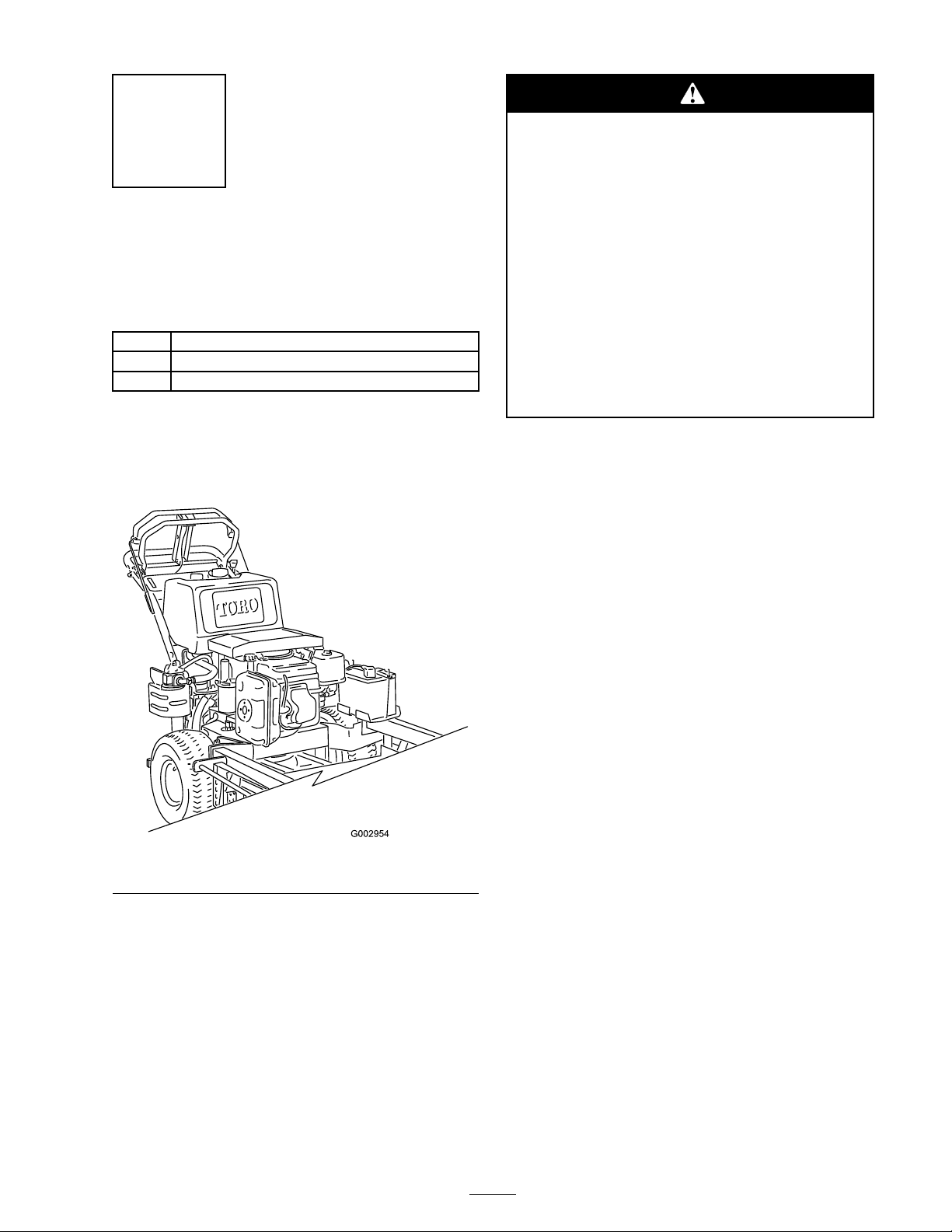
If y our mac hine has handles as sho wn in Figure 3 ,
use the follo wing instr uctions to install the axle .
Figure 3
1. Stop the engine , set the parking brak e , remo v e
the k ey , and w ait for all mo ving par ts to stop
before lea ving the operating position.
2. R emo v e the 6 bolts , spacers , and n uts securing
the bottom of the tw o pulley guards on both
sides of the frame (3 bolts and n uts on eac h
side) ( Figure 4 ). Sa v e all 6 of the bolts and
discard the loc kn uts .
3. Using the 6 bolts (3/8 x 1–3/8 inc hes) and
loc kn uts (3/8 inc h) supplied with the sulk y ,
install the axle as illustrated in Figure 4 .
5
Page 6
Step
2
Installing the Axle on a
Hydraulic Drive Mower with
T2 T-Bar Handles
Parts needed for this step:
1
Axle
Large spacer
2
6
Locknut, (3/8 inch)
6
Bolt, (3/8 x 1-3/4 inches)
Figure 4
Left side of mower shown
1. Bolt, (3/8 x 1–3/8 inches) 4. Locknut, (3/8 inch)
2. Axle mounting bracket 5. Axle
3. Pulley guard
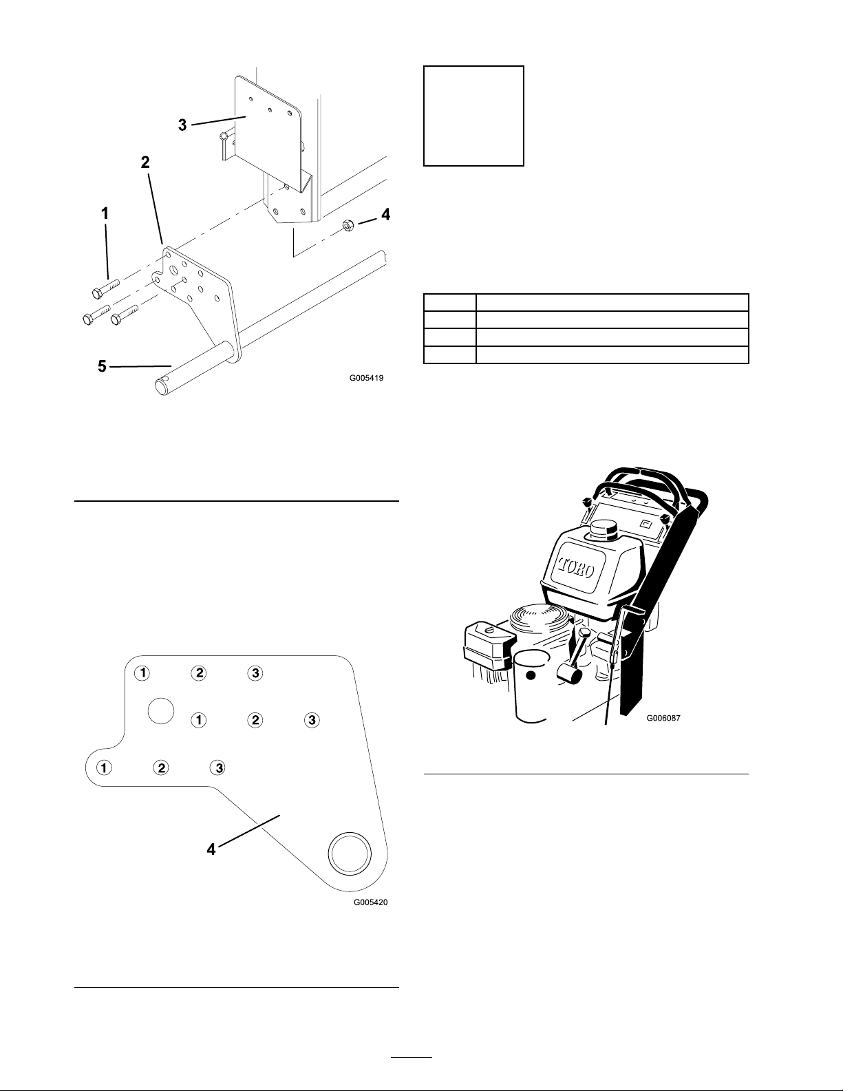
Note: Y ou can install the axle in one of 3
horizontal positions ( Figure 5 ). F or a T -Bar
controlled mac hine , the a v erag e person will g et
the best results using the rear holes; ho w ev er ,
if a larg e person will be using the sulk y , y ou
ma y w ant to install it using the middle or front
holes to gi v e the operator more room.
Procedure
If y our mac hine has handles as sho wn in Figure 6 ,
use the follo wing instr uctions to install the axle .
Figure 6
Figure 5
1. Front holes (pistol grip
machines)
2. Middle holes 4. Axle mounting bracket
3. Rear holes (T-bar machines)
6
Page 7

Impr oper installation or application of a
sulk y can ef fect the sta bility and contr ol of
the Mid-Siz ed Mo w er s, which could cause
per sonal injur y or death.
• W eight kits mounted in the r ear position
need to be r emo v ed when a sulk y is
installed.
• T he par king brak e must be adjusted, on
units equipped with a par king brak e,
when a sulk y is installed.
• T he sulk y is not r ecommended on Mid
Siz e mo w er s equipped with 32 inch
mo w er s.
1. Stop the engine , set the parking brak e , remo v e
the k ey , and w ait for all mo ving par ts to stop
before lea ving the operating position.
2. P osition the axle mounting brac k ets on both
sides of the mac hine frame ( Figure 7 ).
3. Inser t the larg e spacers betw een the axle
mounting brac k ets and the frame , lining up the
holes ( Figure 7 ).
Figure 7
1. Bolt, (3/8 x 1-3/4 inches) 3. Locknut, (3/8 inch)
2. Large spacer
4. Axle mounting bracket
4. Using the 6 bolts (3/8 x 1-3/4 inc hes) and
loc kn uts (3/8 inc h) supplied with the sulk y ,
install the axle as illustrated in Figure 7 .
Note: Y ou can install the axle in one of 3
horizontal positions ( Figure 5 ). F or a T -Bar
controlled mac hine , the a v erag e person will g et
the best results using the rear holes; ho w ev er ,
if a larg e person will be using the sulk y , y ou
ma y w ant to install it using the middle or front
holes to gi v e the operator more room.
7
Page 8

Step
5. Inser t the larg e spacers betw een the axle
mounting brac k ets and the frame , lining up the
holes ( Figure 8 ).
3
Installing the Axle on Gear
Drive Mowers with Pistol
Grip or T-Bar Handles
Parts needed for this step:
1
Axle
2
Small spacer
Large spacer
2
6
Locknut, (3/8 inch)
6
Bolt, (3/8 x 1–3/8 inches)
Bolt, (3/8 x 4/1/2 inches) For use with T-Bar,
2
gear drive machine only.
Procedure
Impr oper installation or application of a
sulk y can ef fect the sta bility and contr ol of
the Mid-Siz ed Mo w er s, which could cause
per sonal injur y or death.
Note: Y ou can install the axle in one of 3
horizontal positions ( Figure 5 ). F or a T -bar
controlled mac hine , the a v erag e person will g et
the best results using the rear holes; ho w ev er ,
if a larg e person will be using the sulk y , y ou
ma y w ant to install it using the middle or front
hole to gi v e the operator more room. F or a
pistol g rip mac hine , use the front holes .
6. Using the 6 bolts (3/8 x 1–3/8 inc hes) and
loc kn uts (3/8 inc h) supplied with the sulk y ,
secure the bottom of the pulley guards , the
ax el, and the spacers as illustrated in Figure 8 .
7. Slide the small spacers betw een the top of the
pulley guards and the mounting tube on the
frame , and secure them using 2 bolts (3/8 x
4-1/2 inc h) and the n uts remo v ed in ste p 3
( Figure 8 ).
• W eight kits mounted in the r ear position
need to be r emo v ed when a sulk y is
installed.
• T he par king brak e must be adjusted, on
units equipped with a par king brak e,
when a sulk y is installed.
• T he sulk y is not r ecommended on Mid
Siz e mo w er s equipped with 32 inch
mo w er s.
1. Stop the engine , set the parking brak e , remo v e
the k ey , and w ait for all mo ving par ts to stop
before lea ving the operating position.
2. R emo v e the 4 bolts and n uts securing the
bottom of the tw o pulley guards on the sides
of the frame (2 bolts and n uts on eac h side)
( Figure 8 ).
3. R emo v e the long bolt and n ut securing the top
of eac h pulley guard ( Figure 8 ). Sa v e the bolt
for whenev er the axle is remo v ed.
4. Inser t the axle mounting brac k ets betw een the
pulley guards and the frame ( Figure 8 ).
Figure 8
1. Bolt, (3/8 x 4-1/2 inches)
2. Pulley guard 6. Axle mounting bracket
3. Small spacer
4. Locknut, (3/8 inch)
5. Large spacer
7. Bolt, (3/8 x 1–3/8 inches)
8
Page 9

Step
4
Installing the Axle on a
Hydraulic Drive Mower with
Pistol Grip Handles
Parts needed for this step:
1
Axle
Large spacer
2
6
Locknut, (3/8 inch)
6
Bolt, (3/8 x 1-3/4 inches)
Procedure
Impr oper installation or application of a
sulk y can ef fect the sta bility and contr ol of
the Mid-Siz ed Mo w er s, which could cause
per sonal injur y or death.
• W eight kits mounted in the r ear position
need to be r emo v ed when a sulk y is
installed.
• T he par king brak e must be adjusted, on
units equipped with a par king brak e,
when a sulk y is installed.
Figure 9
1. Bolt, (3/8 x 1-3/4 inches) 3. Locknut, (3/8 inch)
2. Large spacer
4. Axle mounting bracket
4. Using the 6 bolts (3/8 x 1-3/4 inc hes) and
loc kn uts (3/8 inc h) supplied with the sulk y ,
install the axle as illustrated in Figure 7 .
Note: Y ou ma y ha v e difficulty installing one
of the bolts on the right side due to interference
with the traction control lev er . If this happens ,
disconnect the control rod from the pistol g rip
( Figure 10 ) to drop the lev er out of the w a y .
W hen finished, reconnect the control rod.
• T he sulk y is not r ecommended on Mid
Siz e mo w er s equipped with 32 inch
mo w er s.
1. Stop the engine , set the parking brak e , remo v e
the k ey , and w ait for all mo ving par ts to stop
before lea ving the operating position.
2. P osition the axle mounting brac k ets on both
sides of the mac hine frame ( Figure 9 ).
3. Inser t the larg e spacers betw een the axle
mounting brac k ets and the frame , lining up the
holes ( Figure 9 ).
Note: Y ou can install the axle in one of 3
horizontal positions ( Figure 5 ). F or a pistol
g rip mac hine , use the front holes .
Figure 10
1. Pistol grip 3. Control rod
2. Clevis pin
9
4. Hairpin cotter pin
Page 10

Step
Step
5
Installing the Sulky
Assemblies
Parts needed for this step:
1
Left sulky assembly
1
Right sulky assembly
2
Lynch pin
2
Washer, (1-3/4 inches)
Procedure
1. Slide the mounting tube on eac h sulk y assembly
o v er the ends of the axle with the foot rests
to w ards the inside ( Figure 11 ).
2. Secure the sulk y assemblies using a w asher
(1-3/4 inc h) and lync h pin on eac h side
( Figure 11 ).
3. Grease the sulk y; refer to Greasing the Sulk y .
6
Adjusting the Handle Height
No Parts Required
Procedure
Note: Mac hines with a T2 handle are not
adjustable .
Because the sulk y raises y ou sev eral inc hes
off of the g round, adjust the handle height to
accommodate the user on the sulk y comfor tably .
R efer to the mo w er Operator’ s Manual for more
infor mation on c hanging the handle height.
Step
7
Figure 11
Left side shown
1. Washer, (1–3/4 inches)
2. Sulky assembly 4. Lynch pin
3. Axle
Installing the Lanyard
Parts needed for this step:
2
Lanyard
2
Bolt, (5/16 x 1-1/4 inches)
2 Spacer
2
Small washer
4
Locknut, (5/16 inch)
2
Shoulder bolt
2
Washer, (1/2 inch)
2
Washer, (3/8 inch)
Procedure
1. Install the n ut (5/16 inc h), small w asher ,
spacer , lanyard and bolt (5/16 x 1-1/4 inc hes)
into the center hole ( Figure 12 ).
Note: T he sulk y transpor t position can be
raised or lo w ered. R efer to Adjusting the Sulk y
T ranspor t P osition.
10
Page 11

Figure 12
1. Sulky assembly 5. Small washer
2. Center hole
3. Side support 7. Lanyard
4. Locknut, (5/16 inch) 8. Bolt, (5/16 x 1-1/4 inches)
6. Spacer
Note: T he mac hines with T2 handles do not
need a hole drilled into the side of the mac hine
for installing the lanyard. Proceed to item 6 in
this ste p to install the lanyard ( Figure 15 ).
2. Raise the sulk y and position the lanyard loop
until it is in a clear location on the pulley guard,
both on the outside and inside of the guard
( Figure 13 ).
3. If a hole does not exist in or near this location,
mark the location of the lanyard loop .
Important: T he sulk y must be at least
1-1/2 inches (3.8 cm) fr om an y contact
point such as the machine handle or the
gear shift lev er (when pushed to the right
or left) on gear dri v e machines ( Figur e 13 ).
4. Drill a 11/32 inc h hole at the mark ed location.
5. R emo v e the lanyard from the sulk y assembly .
Figure 13
1. Lanyard 3. Mark location
2. Pulley guard 4. Sulky assembly
6. Install the shoulder bolt, w asher (1/2 inc h),
lanyard, w asher (3/8 inc h), and loc kn ut (5/16
inc h) to the pulley guard ( Figure 14 and
Figure 15 ).
Note: W hen the lanyard is attac hed to the
mac hine , it m ust not be able to be remo v ed
( Figure 14 and Figure 15 ).
Figure 14
1. Shoulder Bolt
2. Washer, (1/2 inch)
3. Lanyard
4. Washer, (3/8 inch)
5. Pulley guard
6. Locknut, (5/16 inch)
11
Page 12
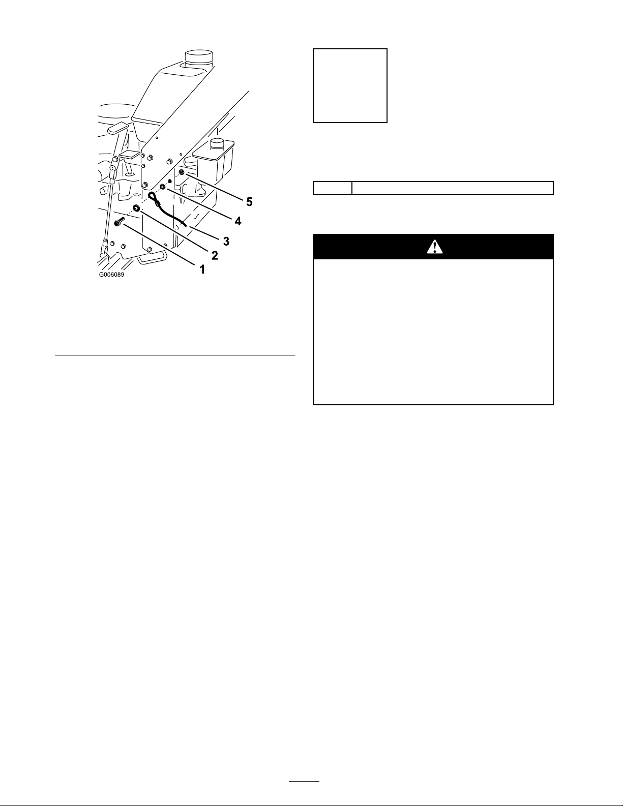
Figure 15
T2 T-Bar Handle Shown
1. Shoulder Bolt
2. Washer, (1/2 inch) 5. Locknut, (5/16 inch)
3. Lanyard
7. Raise the sulk y assembly and attac h the lanyard.
Note: T he sulk y transpor t position can be
raised or lo w ered b y using the three different
holes in the sulk y side suppor t ( Figure 12 ).
8. R e peat these ste ps for the opposite sulk y
assembly .
4. Washer, (3/8 inch)
Step
8
Installing the Weight Kit
Parts needed for this step:
-
Weight Kit (if needed)
Procedure
Use the cor r ect w eight kits when the sulk y
is installed or per sonal injur y or death could
occur .
• Nev er operate the machine with out
r ecommended fr ont w eight kits.
• Do not use r ear w eights when a sulk y is
installed.
• R emo v e all r ear w eights when installing
a sulk y .
Use the follo wing figures to deter mine the w eight
kit needed for y our mo w er . If needed, a w eight kit
is a v ailable through an A uthorized Ser vice Dealer .
Note: If the handle bar is lo w ered the lanyard
ma y ha v e to be re-positioned to attain proper
clearance for the raised sulk y .
R efer to the W eight Kit for the cor rect procedures
to install the w eight.
Important: A w eight kit is r equir ed f or Mid
Siz ed mo w er s equipped with a 44 inch mo w er
deck (Classic mo w er decks)( Figur e 16 ).
W eight Kit, 106–0820, is used on Mid-Size mo w ers
(Classic mo w er dec ks) with a car rier frame and
adjusting rod sho wn in Figure 16 .
12
Page 13

Important: A w eight kit is not r equir ed f or
Mid Siz ed mo w er s with height-of-cut pins
sho wn in Figur e 18 .
T o enhance the perfor mance of the mac hine ,
install W eight Kit(s), 112–9971, onto Mid-Size
mo w ers (TURBO FOR CE mo w er dec ks) with the
style of height-of-cut pins sho wn in Figure 18 .
Use the follo wing table to deter mine the n umber
of w eights recommended to install a T r u T rak
Sulk y on a Mid-Size mo w er with a TURBO
FOR CE mo w er dec k ( Figure 18 ).
®
Figure 16
1. Carrier frame 2. Adjusting rod
Important: A w eight kit is not r equir ed f or
Mid Siz ed mo w er s with height-of-cut pins
sho wn in Figur e 17 and with a serial n umber
of 210000001 thr ough 220000001.
T o enhance the perfor mance of the mac hine ,
install W eight Kit, 106–5491, onto Mid-Size
mo w ers (SFS mo w er dec ks) with the style of
height-of-cut pins sho wn in Figure 17 .
Number of Weights to use with the TRU TRAK
Mid-Size mowers with TUBRO FORCE mower decks only
Gear Driven Mowers
Deck size
36 3
40
48
52 0 2
60
Number
of
Weights
4 Front 4 Front
1 Front
Not Available
Weight
Position
Front 4 Front
Hydraulic Driven
Mowers
Number
of
Weights
3
1 Front
®
Sulky for
Weight
Position
Front
Front
Figure 17
1. Front height-of-cut pin 2. Rear height-of-cut pin
Figure 18
1. Rear height-of-cut pin 2. Front height-of-cut pin
13
Page 14

Step
9
Adjusting the Parking Brake
No Parts Required
Procedure
After installing the sulk y , adjust the mac hine’ s
parking brak e to compensate for the increased
mac hine w eight.
R efer to the Mid-Size mo w er Operator’ s Manual for
the cor rect procedure to adjust the parking brak e .
14
Page 15

Operation
Operating Tips
Note: Deter mine the left and right sides of the
mac hine from the nor mal operating position.
Positioning the Sulky for
Transport
Before placing the mac hine on a trailer , lift eac h
sulk y assembly up and secure them with the
lanyards ( Figure 19 ). T his will k ee p the sulk y from
bouncing during transpor t and mak e the mac hine
more compact.
Learning to Drive
Dri v e slo wly and tak e time to lear n ho w the sulk y
mo v es when using it for the first time .
Turning with a Sulky
Use care when tur ning to ensure that y ou do not
swing y ourself and the sulk y into obstacles .
W hen tur ning, lean forw ard and to w ard the
direction of the tur n to help k ee p y our balance .
Adjusting the Wheel Drive Traction
If y our mac hine is a g ear dri v e , pistol g rip mac hine ,
y ou ma y need to adjust the wheel dri v e tension;
refer to y our mac hine Operator’ s Manual .
Figure 19
1. Lanyard
Removing the Weight
Important: If the sulk y and axle ar e
r emo v ed fr om the machine, install the w eights
to their original position bef or e the sulk y w as
installed.
15
Page 16

Maintenance
Checking the Tire Pressure
Ensure that the caster wheel tires are filled with
air to 50 psi (345 kP a) ev er y 8 operating hours or
before eac h use .
Greasing the Sulky
Grease all g rease fittings ev er y 25 operating hours
and immediately after ev er y w ashing .
Grease type: General-pur pose g rease .
1. Clean the g rease fittings with a rag .
2. Connect a g rease gun to eac h fitting .
3. Pump g rease into the fittings until g rease
begins to ooze out of the bearings .
4. Wipe up any ex cess g rease .
the sulk y wheel is used when the handle is in
the high position. T he middle hole is for the
middle handle height position and the front
hole is for the lo w handle height position.
4. Install the n ut (5/16 inc h), small w asher ,
spacer , lanyard and bolt (5/16 x 1 inc h) into
the desired hole ( Figure 21 ).
Figure 20
Adjusting the Sulky
Transport Position
T he sulk y transpor t position can be raised or
lo w ered b y using the three different holes in the
sulk y side suppor t.
1. R emo v e the n ut (5/16 inc h), small w asher ,
spacer , lanyard and bolt (5/16 x 1-1/4 inc hes)
from the sulk y side suppor t ( Figure 21 ).
2. Deter mine the handle height position. R efer
to the Operator’ s Manual for the handle height
position.
Figure 21
1. Sulky assembly 5. Small washer
2. Center hole
3. Side support 7. Lanyard
4. Locknut, (5/16 inch) 8. Bolt, (5/16 x 1-1/4 inches)
6. Spacer
3. Locate the three adjustment holes in the sulk y
assemblies ( Figure 21 ). T he hole closest to
16
Page 17

Page 18

Page 19

Page 20

Landscape
Contractor
Equipment (LCE)
The Toro Total Coverage Guarantee
A Limited Warranty
Conditions and Products Covered
The Toro® Company and its afliate, Toro Warranty Company, pursuant to an
agreement between them, jointly promise to repair the listed Toro Products if
defective in materials or workmanship. The following time periods apply from
the date of purchase:
This warranty applies to:
•
ProLine Mid-Size Mowers and Attachments
•
Z Master Mid-Mount ZRTs and Attachments
Components
Traction Unit Frame and Carrier Frame
All Spindles
Engines* and /Hydraulic System
Deck Shells (34 ″ -72 ″ )
Z500 Series Electric Clutch
Remaining Components
* S o m e e n g i n e s u s e d o n T o r o L C E P r o d u c t s a r e w a r r a n t e d b y t h e e n g i n e m a n u f a c t u r e r .
This warranty includes the cost of parts and labor, but you must pay
transportation costs.
Warranty Period
1 year
1 year
2 year
3 years Parts
2 years Labor
2 years
2 years
2 years
1 year
Instructions for Obtaining Warranty Service
If you think that your Toro Product contains a defect in materials or
workmanship, follow this procedure:
1. Contact any Toro Authorized or Master Service Dealer to arrange service at
their dealership. To locate a dealer convenient to you, access our website at
www.Toro.com. You may also call our Toro Customer Care Department
toll free at 888–865–5676 (U.S. Customers) or 888–865–5691 (Canada
customers).
2. Bring the product and your proof of purchase (sales receipt) to the Service
Dealer.
If for any reason you are dissatised with the Service Dealer’s analysis or with
the assistance provided, contact us at:
LCB Customer Service Department
Toro Warranty Company
8111 Lyndale Avenue South
Bloomington, MN 55420-1196
Owner Responsibilities
You must maintain your Toro Product by following the maintenance procedures
described in the operator’s manual. Such routine maintenance, whether
performed by a dealer or by you, is at your expense.
Items and Conditions Not Covered
There is no other express warranty except for special emission system coverage
on some products. This express warranty does not cover the following:
• Cost of regular maintenance service or parts, such as lters, fuel, lubricants,
tune-up parts, blade sharpening, brake and clutch adjustments.
• Any product or part which has been altered or misused or required
replacement or repair due to normal wear, accidents, or lack of proper
maintenance.
• Repairs necessary due to improper fuel, contaminants in the fuel system, or
failure to properly prepare the fuel system prior to any period of non-use
over three months.
• Pickup and delivery charges.
General Conditions
All repairs covered by this warranty must be performed by an Authorized Toro
Service Dealer using Toro approved replacement parts.
Neither The Toro® Company nor Toro Warranty Company is liable for
indirect, incidental or consequential damages in connection with the
use of the Toro Products covered by this warranty, including any
cost or expense of providing substitute equipment or service during
reasonable periods of malfunction or non-use pending completion
of repairs under this warranty.
Some states do not allow exclusions of incidental or consequential
damages, or limitations on how long an implied warranty lasts, so
the above exclusions and limitations may not apply to you.
All implied warranties of merchantability (that the product is t
for ordinary use) and tness for use (that the product is t for
a particular purpose) are limited to the duration of the express
warranty.
This warranty gives you specic legal rights, and you may also have
other rights which vary from state to state.
Countries Other than the United States or Canada
Customers who have purchased Toro products exported from the United States or Canada should contact their Toro Distributor (Dealer) to obtain guarantee
policies for your country, province, or state. If for any reason you are dissatised with your Distributor’s service or have difculty obtaining guarantee information,
contact the Toro importer. If all other remedies fail, you may contact us at Toro Warranty Company.
374-0037 Rev F
 Loading...