

Page 1
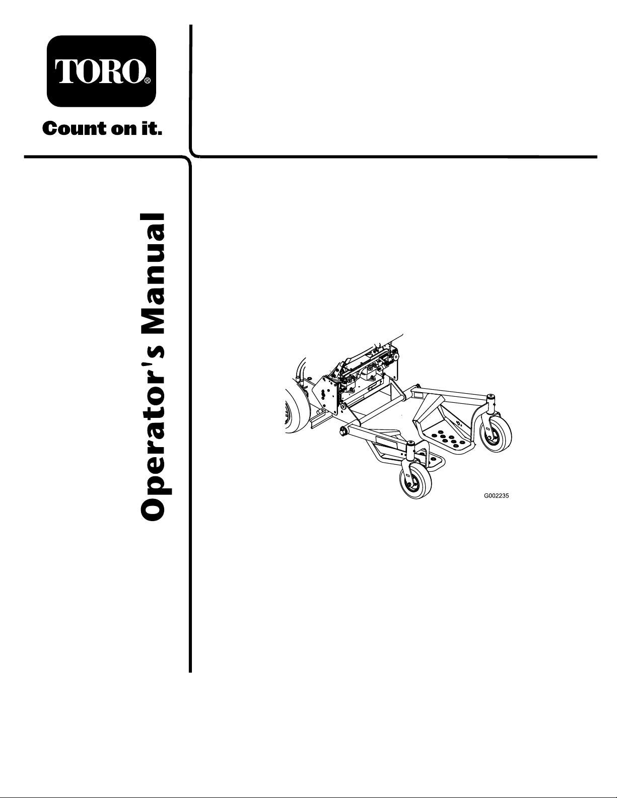
Tru Trak® Sulky
For Fixed Deck Mid-Size Mowers
Model No. 30109
Form No. 3354-303 Rev A
Register your product at www.Toro.com Original Instructions (EN)
Page 2
mec hanical infor mation and Note emphasizes g eneral
infor mation w or th y of special attention.
Introduction
R ead this infor mation carefully to lear n ho w to operate
and maintain y our product properly and to a v oid injur y
and product damag e . Y ou are responsible for operating
the product properly and safely .
Y ou ma y contact T oro directly at www .T oro .com for
product and accessor y infor mation, help finding a
dealer , or to register y our product.
W henev er y ou need ser vice , g en uine T oro par ts , or
additional infor mation, contact an A uthorized Ser vice
Dealer or T oro Customer Ser vice and ha v e the model
and serial n umbers of y our product ready . Figure 1
identifies the location of the model and serial n umbers
on the product. W rite the n umbers in the space
pro vided.
Figure 1
1. Model and serial number location
Contents
Introduction . . . . . . . . . . . . . . . . . . . . . . . . . . . . . . . . . . . . . . . . . . . . . . . . . . . . . . . . . 2
Safety . . . . . . . . . . . . . . . . . . . . . . . . . . . . . . . . . . . . . . . . . . . . . . . . . . . . . . . . . . . . . . . . . . 3
Safe Operating Practices . . . . . . . . . . . . . . . . . . . . . . . . . . . . . . . . . . 3
Setup . . . . . . . . . . . . . . . . . . . . . . . . . . . . . . . . . . . . . . . . . . . . . . . . . . . . . . . . . . . . . . . . . . . 4
1 Installing the Axle on a Hy dro Dri v e
Mo w er . . . . . . . . . . . . . . . . . . . . . . . . . . . . . . . . . . . . . . . . . . . 5
2 Installing the Axle on a Gear Dri v e
Mo w er . . . . . . . . . . . . . . . . . . . . . . . . . . . . . . . . . . . . . . . . . . . 6
3 Installing the Sulk y Assemblies . . . . . . . . . . . . . . . . . . . . . . . 7
4 Adjusting the Handle Height . . . . . . . . . . . . . . . . . . . . . . . . . 7
5 Adjusting the Dri v e Belts on a Gear Dri v e
Mac hine . . . . . . . . . . . . . . . . . . . . . . . . . . . . . . . . . . . . . . . . . 7
6 Installing the Lanyard on a Hy dro Dri v e
Mac hine . . . . . . . . . . . . . . . . . . . . . . . . . . . . . . . . . . . . . . . . . 8
7 Installing the Lanyard on a Gear Dri v e
Mac hine . . . . . . . . . . . . . . . . . . . . . . . . . . . . . . . . . . . . . . . . . 8
8 Installing the Lanyard Adjustment
Bolts . . . . . . . . . . . . . . . . . . . . . . . . . . . . . . . . . . . . . . . . . . . . . . 9
9 Installing the W eight Kit . . . . . . . . . . . . . . . . . . . . . . . . . . . . . . 11
10 Adjusting the P arking Brak e . . . . . . . . . . . . . . . . . . . . . . . 11
Operation . . . . . . . . . . . . . . . . . . . . . . . . . . . . . . . . . . . . . . . . . . . . . . . . . . . . . . . . . . 12
P ositioning the Sulk y for T ranspor t . . . . . . . . . . . . . . . . . 12
Operating Tips . . . . . . . . . . . . . . . . . . . . . . . . . . . . . . . . . . . . . . . . . . . . 12
Maintenance . . . . . . . . . . . . . . . . . . . . . . . . . . . . . . . . . . . . . . . . . . . . . . . . . . . . . . . 13
Chec king the Tire Pressure . . . . . . . . . . . . . . . . . . . . . . . . . . . . 13
Greasing the Sulk y . . . . . . . . . . . . . . . . . . . . . . . . . . . . . . . . . . . . . . . . 13
Adjusting the Sulk y T ranspor t P osition . . . . . . . . . . . . 13
Model No.
Serial No.
T his man ual identifies potential hazards and has
safety messag es identified b y the safety aler t symbol
( Figure 2 ), whic h signals a hazard that ma y cause
serious injur y or death if y ou do not follo w the
recommended precautions .
Figure 2
1. Safety alert symbol
T his man ual uses 2 other w ords to highlight
infor mation. Impor tant calls attention to special
© 2005—The Toro® Company
8111 Lyndale Avenue South
Bloomington, MN 55420
Contact us at www.Toro.com.
2
Printed in the USA.
All Rights Reserved
Page 3

Safety
Improper use or maintenance b y the operator or
o wner can result in injur y . T o reduce the potential
for injur y , comply with these safety instr uctions
and alw a ys pa y attention to the safety aler t symbol,
whic h means CA UTION , W ARNING , or
D ANGER -“personal safety instr uction." F ailure
to comply with the instr uction ma y result in
personal injur y or death.
Safe Operating Practices
General Operation
• Do not modify the sulk y or use it on
non-appro v ed mac hines .
• Ensure that the sulk y is properly attac hed to
the mac hine and is in g ood w orking order
prior to use .
• Allo w only the mac hine operator on the sulk y .
• Do not allo w use of the sulk y b y untrained
operators .
• Use appropriate personal protecti v e apparatus
for eyes , ears , feet, hands , and head.
• Practice operating the mac hine without the
sulk y until familiar with the controls .
• Practice operation of the mac hine with sulk y
attac hed on larg e open, lev el ter rain with no
obstacles present before use . T he sulk y will
affect the mac hine operation, especially on
slopes , when tur ning, and when stopping .
• Use caution when riding the sulk y o v er curbs ,
roc ks , roots , or other obstr uctions .
• Slo w do wn before making tur ns and use extra
caution on rough ter rain and on slopes .
• T ra v el across slopes , a v oiding operation on
stee p slopes .
• Look behind and do wn before bac king up to
be sure of a clear path. Use extra care when
operating in rev erse .
• Dismount and latc h the sulk y in the transpor t
position when loading and unloading the
mac hine .
3
Page 4

Setup
Loose Parts
Use the chart below to verify that all parts have been shipped.
Step
Axle
1
2
3
4
5
6
7
8
New long spacer (2–3/4 inches)
Locknut, (3/8 inch)
Axle
Flat spacer
Locknut, (3/8 inch)
Bolt, (3/8 x 1-3/4 inches)
Left sulky assembly
Right sulky assembly
Lynch pin
Washer, (1-3/4 inches)
No parts required
No parts required
Lanyard
Shoulder bolt, (5/16 x 1-1/4 inches)
Washer, (1–3/8 inch O.D.)
Flange nut, (3/8 inch)
Locknut, (3/8 inch)
Lanyard
Shoulder bolt, (5/16 x 1-1/4 inches)
Washer, (1–3/8 inch O.D.)
Locknut, (3/8 inch)
Carriage bolt, (5/16 x 1 inch)
Spacer 2
Washer, (1 inch O.D.)
Locknut, (5/16 inch)
Description
Qty.
1
4
4
1
2
4
4
1
1
2
2
–
–
2
2
2
2
2
2
2
2
2
2
2
2
Install the axle on a hydro drive
mower.
Install the axle on a gear drive
mower.
Install the sulky assemblies.
Adjust the handle height.
Adjust the drive belts on a gear
drive machine.
Install the lanyard on a hydro drive
machine.
Install the lanyard on the gear drive
machine.
Install the lanyard adjustment bolts.
Use
9
10
Weight Kit (if needed)
No parts required
4
1 or 2
–
Install the weight kit.
Adjust the parking brake.
Page 5
Step
1
Installing the Axle on a
Hydro Drive Mower
Parts needed for this step:
1
Axle
4
New long spacer (2–3/4 inches)
4
Locknut, (3/8 inch)
Procedure
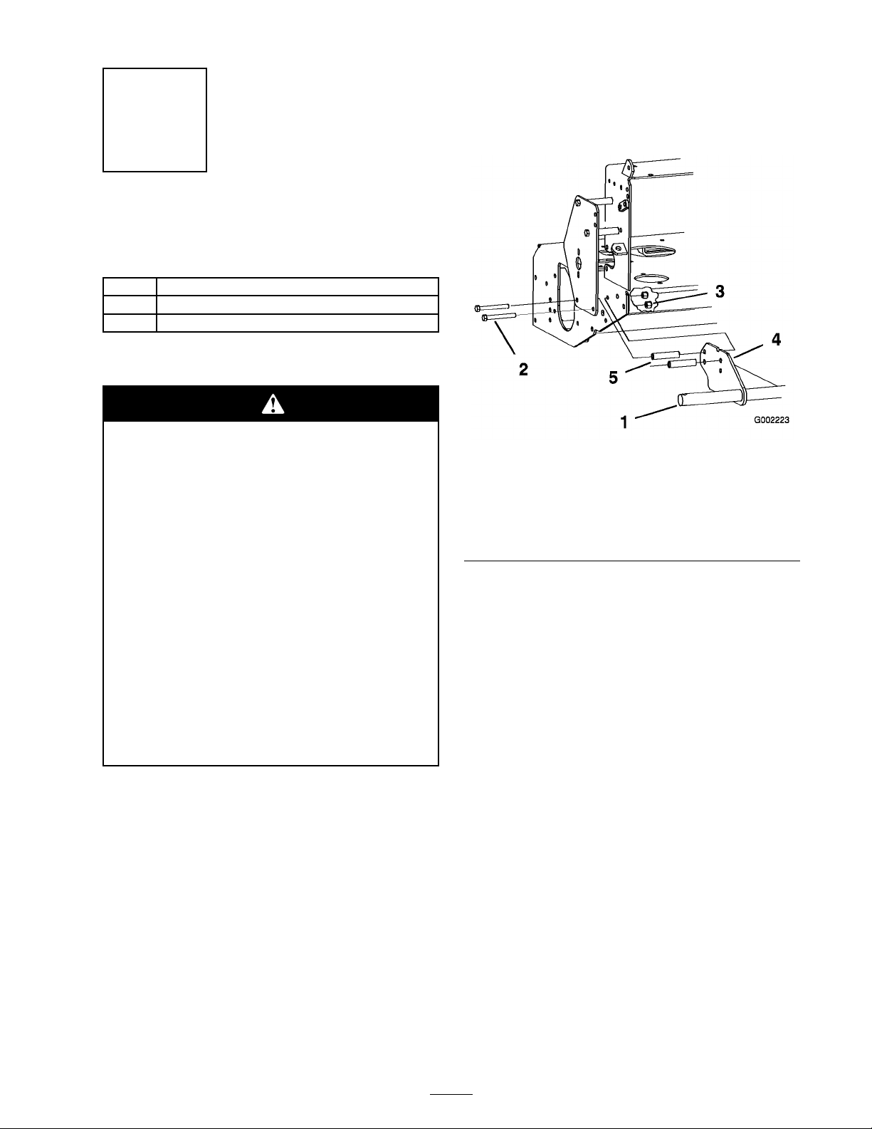
5. Inser t the new long spacers (2–3/4 inc hes)
betw een the axle mounting brac k ets and
the frame on both sides , lining up the holes
( Figure 3 ).
Impr oper installation or application of a
sulk y can ef fect the sta bility and contr ol of
the Mid-Siz ed Mo w er s, which could cause
per sonal injur y or death.
• W eight kits mounted in the r ear position
need be r emo v ed when a sulk y is
installed.
• W eight Kits installed in the fr ont position
ar e r equir ed on Fix ed Deck Mid Siz e
mo w er s that ar e equipped with a sulk y .
• T he par king brak e must be adjusted, on
units equipped with a par king brak e,
when a sulk y is installed.
• T he sulk y is not r ecommended on Fix ed
Deck Mid Siz e mo w er s equipped with
32 inch mo w er s.
1. Diseng ag e the PTO , mo v e the motion control
lev ers to the neutral loc k ed position and set
the parking brak e .
2. Stop the engine , remo v e the k ey , and w ait for
all mo ving par ts to stop before lea ving the
operating position.
Figure 3
Left side of mower shown
1. Axle 4. Axle mounting bracket
2. Previously removed bolt,
(3/8 x 4 inches)
3. Locknut, (3/8 inch)
5. New long spacer (2–3/4
inches)
6. Install the axle to left side of the mac hine using
2 bolts previously remo v ed and 2 loc kn uts
(3/8 inc h) in the top holes in the axle ( Figure 3
and Figure 4 ).
7. Using the upper rear hole , install the axle to
right side of the mac hine using 1 previously
remo v ed bolt (3/8 x 4 inc hes), 1 new long
spacer (2–3/4 inc hes), and 1 loc kn ut (3/8 inc h)
( Figure 4 and Figure 5 ).
8. Using the upper front hole , install the axle to
right side of the mac hine using 1 bolt (3/8
x 4-1/2 inc h) previously remo v ed, 1 new
long spacer (2–3/4 inc hes), 1 shor t spacer
previously remo v ed on the outside of the
guard, and 1 loc kn ut (3/8 inc h) ( Figure 4 and
Figure 5 ).
3. R emo v e the 4 bolts , spacers , and n uts securing
the bottom of the tw o linkag e guards on both
sides of the frame (2 bolts and n uts on eac h
side and spacers on the right side) ( Figure 3 ).
Sa v e all 4 of the bolts and discard the loc kn uts .
4. Inser t the axle mounting brac k ets betw een the
linkag e guards and the frame ( Figure 3 ).
5
Page 6

Figure 4
1. For hydro machines 2. For gear drive machines
Step
2
Installing the Axle on a Gear
Drive Mower
Parts needed for this step:
1
Axle
2
Flat spacer
4
Locknut, (3/8 inch)
4
Bolt, (3/8 x 1-3/4 inches)
Procedure
Impr oper installation or application of a
sulk y can ef fect the sta bility and contr ol of
the Mid-Siz ed Mo w er s, which could cause
per sonal injur y or death.
Figure 5
1. Linkage guard 5. Axle mounting bracket
2. Axle
3. Previously removed bolt,
(3/8 x 4–1/2 inches)
4. Locknut, (3/8 inch)
6. New long spacer (2–3/4
inches)
7. Short spacer
8. Previously removed bolt
(3/8 x 4 inches)
• W eight kits mounted in the r ear position
need be r emo v ed when a sulk y is
installed.
• W eight Kits installed in the fr ont position
ar e r equir ed on Fix ed Deck Mid Siz e
mo w er s that ar e equipped with a sulk y .
• T he par king brak e must be adjusted, on
units equipped with a par king brak e,
when a sulk y is installed.
• T he sulk y is not r ecommended on Fix ed
Deck Mid Siz e mo w er s equipped with
32 inch mo w er s.
1. Diseng ag e the PTO , mo v e the motion control
lev ers to the neutral loc k ed position and set
the parking brak e .
2. Stop the engine , remo v e the k ey , and w ait for
all mo ving par ts to stop before lea ving the
operating position.
3. Inser t the axle mounting brac k ets betw een the
pulley guards and the frame ( Figure 6 ).
4. Inser t the flat spacers betw een the axle
mounting brac k ets and the frame , lining up the
holes ( Figure 6 ).
5. Using the bottom holes in the axle mounting
brac k et, install the 4 bolts (3/8 x 1-1/4 inc hes)
6
Page 7

and loc kn uts (3/8 inc h) supplied with the sulk y ,
secure the axle and the spacers as illustrated in
Figure 4 and Figure 6 .
Figure 7
Figure 6
1. Linkage guard
2. Axle mounting bracket 5. Flat spacer
3. Bolt, (3/8 x 1-1/4 inches)
Step
3
Installing the Sulky
Assemblies
Parts needed for this step:
1
Left sulky assembly
1
Right sulky assembly
2
Lynch pin
2
Washer, (1-3/4 inches)
Procedure
4. Locknut, (3/8 inch)
6. Axle
Left side shown
1. Axle
2. Sulky assembly 4. Lynch pin
3. Grease the sulk y; refer to Greasing the Sulk y .
3. Washer, (1–3/4 inches)
Step
4
Adjusting the Handle Height
No Parts Required
Procedure
Because the sulk y raises y ou sev eral inc hes
off of the g round, adjust the handle height to
accommodate the user on the sulk y comfor tably .
R efer to the mo w er Operator’ s Manual for more
infor mation on c hanging the handle height.
1. Slide the mounting tube on eac h sulk y assembly
o v er the ends of the axle with the foot rests
to w ards the inside ( Figure 7 ).
2. Secure the sulk y assemblies using a w asher
(1-3/4 inc h) and lync h pin on eac h side
( Figure 7 ).
7
Page 8

Step
5
Adjusting the Drive Belts on
a Gear Drive Machine
No Parts Required
Procedure
Because the sulk y increases the w eight of the
mac hine , c hec k the dri v e belts for adjustments .
R efer to the mo w er Operator’ s Manual for more
infor mation on adjusting the dri v e belts .
Step
6
Installing the Lanyard on a
Hydro Drive Machine
Parts needed for this step:
2
Lanyard
2
Shoulder bolt, (5/16 x 1-1/4 inches)
2
Washer, (1–3/8 inch O.D.)
2
Flange nut, (3/8 inch)
2
Locknut, (3/8 inch)
Figure 8
1. Linkage guard 3. Drill a 11/32 inch hole here
2. Upper rear hole
4. Drill the hole for the opposite side .
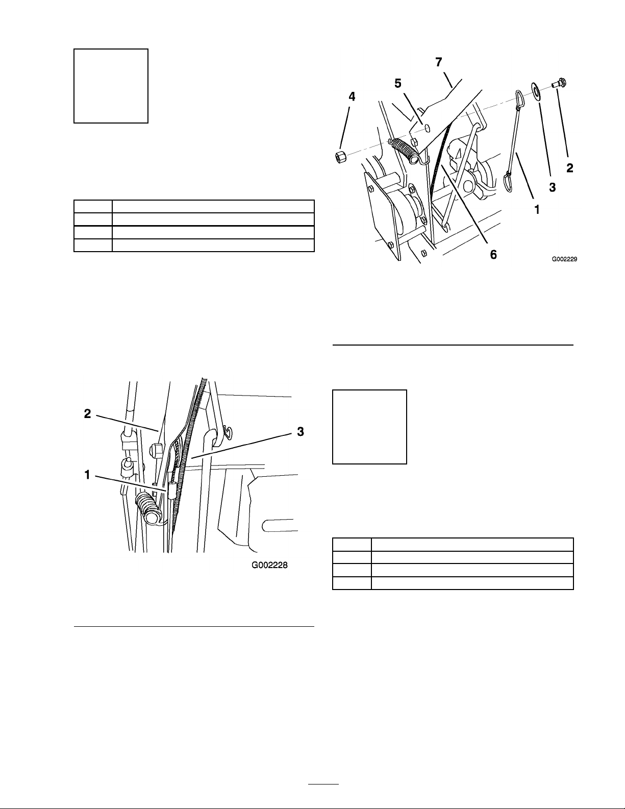
5. Install the lanyard to the rear hole in the
linkag e guard as sho wn in Figure 9 . Secure the
lanyard with 1 shoulder bolt, 1 flang e n ut, 1
w asher (1–3/8 inc hes O .D .) and 1 loc kn ut (3/8
inc h) ( Figure 9 ).
Procedure
1. Inspect the linkag e guard and deter mine if
there is an extra hole in the guard belo w the
upper rear hole . R efer to Figure 8 for the
cor rect location. If there is no existing hole ,
perfor m items 2 and 3 for drilling a hole .
If a hole exists , proceed to item 4 of this
procedure .
2. Measure 1 inc h (25 mm) directly under the
existing hole in the linkag e guard.
3. Mark the location and drill a 11/32 inc h hole
into the linkag e guard ( Figure 8 ).
Figure 9
1. Lanyard
2. Linkage guard 6. Hole to install lanyard
3. Shoulder Bolt 7. Flange nut
4. Washer, (1–3/8 inches
O.D.)
6. Install the other lanyard on the opposite side
using the previous instr uctions .
8
5. Locknut, (5/16 inch)
Page 9
Step
7
Installing the Lanyard on a
Gear Drive Machine
Parts needed for this step:
2
Lanyard
2
Shoulder bolt, (5/16 x 1-1/4 inches)
2
Washer, (1–3/8 inch O.D.)
2
Locknut, (3/8 inch)
Procedure
1. R emo v e the bolt and n ut in the upper hole
where the handle is connected to the frame .
Note: T he lanyard on the left side needs to
be betw een the frame and the throttle cable
( Figure 10 ).
Figure 10
1. Lanyard 3. Throttle cable
2. Handle
Figure 11
1. Lanyard 5. Upper hole
2. Shoulder Bolt 6. Throttle cable
3. Washer, (1–3/8 inches
O.D.)
4. Locknut, (5/16 inch)
3. Install the other lanyard on the opposite side
using the previous instr uctions .
7. Handle
Step
8
Installing the Lanyard
Adjustment Bolts
Parts needed for this step:
2
Carriage bolt, (5/16 x 1 inch)
2 Spacer
2
Washer, (1 inch O.D.)
2
Locknut, (5/16 inch)
Procedure
2. Install the lanyard with 1 shoulder bolt, 1
w asher (1–3/8 inc hes O .D .) and 1 loc kn ut (3/8
inc h) ( ).
1. Deter mine the handle height position. R efer
to the mo w er Operator’ s Manual for the handle
height position.
2. Locate the three adjustment holes in the sulk y
assemblies ( Figure 12 ). T he hole closest to
the sulk y wheel is used when the handle is in
the high position. T he middle hole is for the
middle handle height position and the front
hole is for the lo w handle height position.
9
Page 10

3. Install the n ut (5/16 inc h), w asher (1 inc h
O .D .), spacer and bolt (5/16 x 1 inc h) into
the cor rect hole location deter mined abo v e
( Figure 12 ).
4. Install the other adjustment bolt on the
opposite side .
1. Sulky assembly
2. Side support
3. Carriage bolt,(5/16 x 1
inch)
4. Washer, (1 inch O.D.)
Figure 12
5. Spacer
6. Locknut, (5/16 inch)
7. Center hole
8. Sulky wheel
10
Page 11

Step
9
Installing the Weight Kit
Due to the added w eight of the sulk y and the
operator at the rear of the mac hine , cer tain
mac hines require additional front w eight kits
installed in order to meet safety standards .
Important: If the sulk y and axle ar e
r emo v ed fr om the machine, r emo v e an y
w eights f or use with the sulk y .
Parts needed for this step:
1 or 2
Procedure
Use the cor r ect w eight kits when the sulk y
is installed or per sonal injur y or death could
occur .
• Nev er operate the machine with out
• Do not use the r ear w eight kit when a
Weight Kit (if needed)
r ecommended fr ont w eight kits.
sulk y is installed.
Number of Weight Kits Required when a Sulky is installed.
Mower Deck Size
32 inch Do not use a sulky on
36 inch
40 inch No model available
48 inch
Important: Do not use r ear w eight kit when
the sulk y is installed.
Use the follo wing table to deter mine whic h models
require front w eights and the n umber of front
w eight kits needed when installing a sulk y . F ront
w eight kits are a v ailable through an A uthorized
Ser vice Dealer . R efer to the w eight kit for the
cor rect procedures to install the w eight.
All 2005 and Earlier
Models
32 inch mowers.
2
1 1
2006 and After Pistol Grip,
Hydro Models Only
Do not use a sulky on 32
inch mowers.
1
2
Step
10
Adjusting the Parking Brake
No Parts Required
Procedure
After installing the sulk y , adjust the mac hine’ s
parking brak e to compensate for the increased
mac hine w eight.
11
Page 12

Operation
Note: Deter mine the left and right sides of the
mac hine from the nor mal operating position.
W hen tur ning, lean forw ard and to w ard the
direction of the tur n to help in k ee ping y our
balance .
Adjusting the Wheel Drive Traction
Positioning the Sulky for
Transport
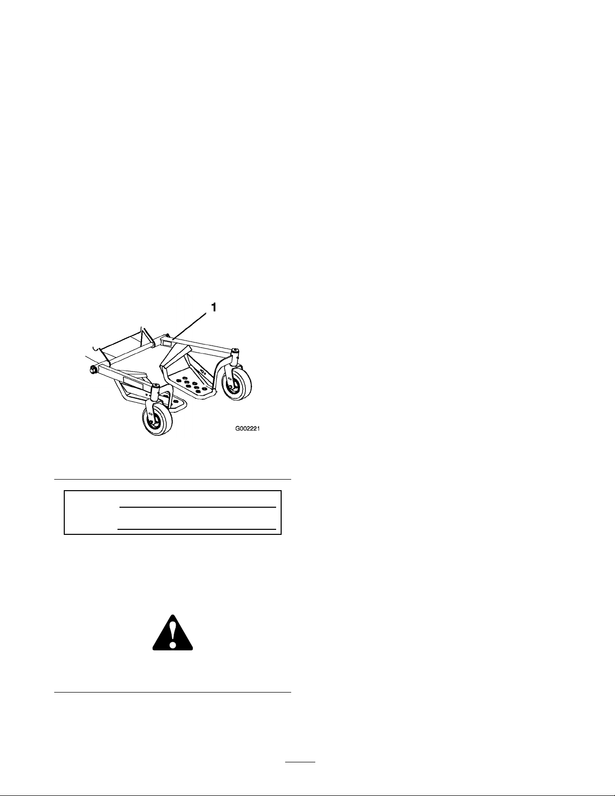
Before placing the mac hine on a trailer , lift eac h
sulk y assembly up and secure them with the
lanyards ( Figure 13 ). T his will k ee p the sulk y from
bouncing during transpor t and mak e the mac hine
more compact.
If y our mac hine is a g ear dri v e , pistol g rip mac hine ,
y ou ma y need to adjust the wheel dri v e tension;
refer to y our mac hine Operator’ s Manual .
Figure 13
1. Lanyard
Operating Tips
Learning to Drive
Dri v e slo wly and tak e time to lear n ho w the sulk y
mo v es when using it for the first time .
Turning with a Sulky
Use care when tur ning to ensure that y ou do not
swing y ourself and the sulk y into obstacles .
12
Page 13

Maintenance
Checking the Tire Pressure
Ensure that the caster wheel tires are filled with
air to 50 psi (345 kP a) ev er y 8 operating hours or
before eac h use .
Greasing the Sulky
Grease all g rease fittings ev er y 25 operating hours
and immediately after ev er y w ashing .
Grease type: General-pur pose g rease .
1. Clean the g rease fittings with a rag .
2. Connect a g rease gun to eac h fitting .
3. Pump g rease into the fittings until g rease
begins to ooze out of the bearings .
4. Wipe up any ex cess g rease .
the sulk y wheel is used when the handle is in
the high position. T he middle hole is for the
middle handle height position and the front
hole is for the lo w handle height position.
4. Install the n ut (5/16 inc h), small w asher ,
spacer , lanyard and bolt (5/16 x 1 inc h) into
the desired hole ( Figure 15 ).
Figure 14
Adjusting the Sulky
Transport Position
T he sulk y transpor t position can be raised or
lo w ered b y using the three different holes in the
sulk y side suppor t.
1. R emo v e the n ut (5/16 inc h), small w asher ,
spacer , lanyard and bolt (5/16 x 1-1/4 inc hes)
from the sulk y side suppor t ( Figure 15 ).
2. Deter mine the handle height position. R efer
to the Operator’ s Manual for the handle height
position.
3. Locate the three adjustment holes in the sulk y
assemblies ( Figure 15 ). T he hole closest to
Figure 15
13
Page 14

Page 15

Page 16

 Loading...