

Page 1
Preface
This publications provides the service technician with
information for troubleshooting, testing, and repair of the
Hydroject.
Part No. 04134SL (Rev. B)
Service Manual
Hydroject ® 3010
REFER TO THE HYDROJECT OPERATOR’S MANUAL FOR OPERATING, MAINTENANCE AND ADJUSTMENT INSTRUCTIONS. Space is provided in
Chapter 2 of this book to insert the Operator’s Manual
and Parts Catalog for your machine. A replacement
Operator’s Manual is available by sending the complete
Model and Serial Number of the machine to:
The Toro Company
8111 Lyndale Avenue South
Bloomington, MN 55420
The T oro Company reserves the right to change product
specifications or this publication without notice.
This safety symbol means DANGER,
WARNING, or CAUTION, PERSONAL SAFETY
INSTRUCTION. When you see this symbol,
carefully read the instructions that follow.
Failure to obey the instructions may result in
personal injury.
NOTE: A NOTE will give general information about the
correct operation, maintenance, service, testing or repair of the machine.
IMPORTANT: The IMPORTANT notice will give important instructions which must be followed to prevent damage to systems or components on the
machine.
© The Toro Company 2005, 2006, 2007
Page 2

Hydroject 3010
Page 3

Table Of Contents
Chapter 1 - Safety
Safety Instructions . . . . . . . . . . . . . . . . . . . . . . . . 1 - 1
Chapter 2 - Product Records and Manuals
Product Records. . . . . . . . . . . . . . . . . . . . . . . . . . 2 - 1
Maintenance
Equivalents and Conversions . . . . . . . . . . . . . . . . 2 - 2
Torque Specifications . . . . . . . . . . . . . . . . . . . . . . 2 - 3
Chapter 3 - Engine
Specifications . . . . . . . . . . . . . . . . . . . . . . . . . . . . 3 - 1
Repairs . . . . . . . . . . . . . . . . . . . . . . . . . . . . . . . . . 3 - 2
Kohler Engine Service Manual
Chapter 4 - Hydraulic System
Specifications . . . . . . . . . . . . . . . . . . . . . . . . . . . . 4 - 2
General Information
Hydraulic Diagram
Special Tools . . . . . . . . . . . . . . . . . . . . . . . . . . . . 4 - 7
Troubleshooting
Testing . . . . . . . . . . . . . . . . . . . . . . . . . . . . . . . . . 4 - 9
Adjustments
Repairs . . . . . . . . . . . . . . . . . . . . . . . . . . . . . . . . 4 - 14
. . . . . . . . . . . . . . . . . . . . . . . . . . . . . 2 - 1
. . . . . . . . . . . . . . . . . . . . . . . 4 - 3
. . . . . . . . . . . . . . . . . . . . . . . . 4 - 6
. . . . . . . . . . . . . . . . . . . . . . . . . . 4 - 8
. . . . . . . . . . . . . . . . . . . . . . . . . . . . 4 - 11
Chapter 5 - Electrical System
Wiring Schematics and Diagrams. . . . . . . . . . . . . 5 - 2
Special Tools. . . . . . . . . . . . . . . . . . . . . . . . . . . . . 5 - 5
Troubleshooting
Testing
Repairs . . . . . . . . . . . . . . . . . . . . . . . . . . . . . . . . 5 - 24
Chapter 6 - Water System
Specifications . . . . . . . . . . . . . . . . . . . . . . . . . . . . 6 - 2
Water System Schematic . . . . . . . . . . . . . . . . . . . 6 - 3
Special Tools. . . . . . . . . . . . . . . . . . . . . . . . . . . . . 6 - 4
Troubleshooting . . . . . . . . . . . . . . . . . . . . . . . . . . 6 - 9
Testing
Adjustments
Repairs . . . . . . . . . . . . . . . . . . . . . . . . . . . . . . . . 6 - 20
Chapter 7 - Wheels, Steering and Brakes
Adjustments . . . . . . . . . . . . . . . . . . . . . . . . . . . . . 7 - 2
Repairs . . . . . . . . . . . . . . . . . . . . . . . . . . . . . . . . . 7 - 3
Chapter 8 - Electrical Diagrams
Schematic . . . . . . . . . . . . . . . . . . . . . . . . . . . . . . . 8 - 3
Main Harness . . . . . . . . . . . . . . . . . . . . . . . . . . . . 8 - 4
Main Wiring Diagram
Control Panel Harness . . . . . . . . . . . . . . . . . . . . . 8 - 6
Control Panel Wiring Diagram . . . . . . . . . . . . . . . 8 - 7
Tiller Harness and Wiring Diagram
. . . . . . . . . . . . . . . . . . . . . . . . . . . . . . . . 5 - 15
. . . . . . . . . . . . . . . . . . . . . . . . . . . . . . . . 6 - 12
. . . . . . . . . . . . . . . . . . . . . . . . . . 5 - 7
. . . . . . . . . . . . . . . . . . . . . . . . . . . . 6 - 18
. . . . . . . . . . . . . . . . . . . . . . 8 - 5
. . . . . . . . . . . . 8 - 8
Hydroject 3010
Page 4

Hydroject 3000/4000
Page 5
Table of Contents
Chapter 1
Safety
SAFETY INSTRUCTIONS . . . . . . . . . . . . . . . . . . . . . . 1
Before Operating . . . . . . . . . . . . . . . . . . . . . . . . . . . . 1
While Operating . . . . . . . . . . . . . . . . . . . . . . . . . . . . . 2
Safety Instructions
Although hazard control and accident prevention partially are dependent upon the design and configuration
of the machine, these factors are also dependent upon
the awareness, concern, and proper training of the per
sonnel involved in the operation, transport, maintenance, and storage of the machine. Improper use or
maintenance of the machine can result in injury or
death. To reduce the potential for injury or death, comply
with the following safety instructions.
Before Operating
1. Read and understand the contents of this manual
before starting and operating the machine. Become fa
miliar with all controls and know how to stop quickly. A
free replacement manual is available by sending com
plete Model and Serial Numbers to:
The Toro Company
8111 Lyndale Avenue South
Bloomington, Minnesota 55420
Use the Model and Serial Number when referring to your
machine. If you have questions about this Service
Manual, please contact:
The Toro Company
Commercial Service Department
8111 Lyndale Avenue South
Bloomington, Minnesota 55420
2. Never allow children to operate the machine. Do not
allow adults to operate machine without proper instruc
tion. Only trained operators who have read this manual
should operate this machine.
-
-
-
-
Maintenance and Service . . . . . . . . . . . . . . . . . . . . . 3
SAFETY AND INSTRUCTION DECALS
. . . . . . . . . . 4
CAUTION
TO REDUCE THE POTENTIAL FOR INJURY
OR DEATH, COMPLY WITH THE FOLLOWING
SAFETY INSTRUCTIONS.
3. Never operate the machine when under the influ-
ence of drugs or alcohol.
4. Before attempting to start engine engage parking
brake.
5. Remove all debris or other objects that might interfere with operation. Keep all bystanders away from the
work area.
6. Keep all shields and safety devices in place. If a
shield, safety device or decal is defective or damaged,
repair or replace it before operation is commenced. Also
tighten any loose nuts, bolts and screws to assure ma
chine is in safe operating condition.
7. Do not operate machine while wearing sandals, tennis shoes, sneakers or shorts. Also, do not wear loose
fitting clothing which could get caught in moving parts.
Always wear long pants and substantial shoes. Wearing
safety glasses, safety shoes, ear protection and a hel
met is advisable and required by some local ordinances
and insurance regulations.
-
-
Hydroject 3010
Page 1 – 1
Safety
Page 6

8. Fill fuel tank with gasoline before starting the en-
gine. Avoid spilling gasoline. Since gasoline is flammable, handle it carefully.
A. Use an approved gasoline container.
B. Do not fill tank while engine is hot or
running.
C. Do not smoke while handling gasoline.
While Operating
D. Fill fuel tank outdoors and up to about one
inch (25 mm) from top of the tank, not the
filler neck.
E. Wipe up any spilled gasoline.
9. Check interlock switches daily for proper operation.
If a switch fails, replace it before operating the machine.
The interlock system is for your protection, so do not by
pass it. Replace all interlock switches every two years.
-
10. DON’T TAKE AN INJURY RISK! When a person or
pet appears unexpectedly in or near the WORKING
area, STOP AERATING.
11. Keep hands and feet away from nozzle and roller
area. High velocity water jets can penetrate hands and
feet. Penetration by the high velocity water jets can
cause serious personal injury. If accidental penetration
occurs, seek medical attention immediately.
12. Never use chemicals in the water supply system.
13. Do not operate water injection system on concrete
or asphalt because water jets will permanently damage
these surfaces.
14. Start engine with parking brake engaged.
15. Do not run the engine in a confined area without ad-
equate ventilation. Exhaust fumes are hazardous and
could possibly be deadly.
16. Using the machine demands attention, and to prevent loss of control:
Maintenance
A. Use only in daylight or when there is good
artificial light.
B. Watch for holes or other hidden hazards.
C. Do not transport machine close to a sand
trap, ditch, creek or other hazard.
17. If the machine starts to vibrate abnormally, shut the
engine off. Remove wires from spark plugs to prevent
possibility of accidental starting. Check machine for
damage and defective parts. Repair any damage before
restarting the engine and operating the machine.
18. Do not touch engine or muffler while engine is running or soon after it is stopped. These areas could be hot
enough to cause a burn.
19. Before leaving the operator’s position–behind handle–engage parking brake.
20. When leaving the machine unattended, engage
parking brake , shut engine OFF and remove key from
ignition switch.
21. Disconnect wires from spark plugs to prevent accidental starting of the engine when servicing, adjusting or
storing the machine.
22. If machine must be tipped to perform maintenance
or an adjustment, close fuel shut–off valve, drain gaso
line from fuel tank, oil from crankcase and remove battery.
23. To reduce potential fire hazard, keep the engine free
of excessive grease, grass, leaves and accumulations
of dirt.
24. Be sure machine is in safe operating condition by
keeping nuts, bolts and screws tight. Check all bolts and
nuts frequently to be sure they are tightened to specifi
cation.
25. If the engine must be running to perform a maintenance adjustment, keep hands, feet, clothing and other
parts of the body away from any moving parts.
26. Make sure all hydraulic line connectors are tight, and
all hydraulic hoses and lines are in good condition be
fore applying pressure to the system.
Safety Hydroject 3010
Page 1 – 2
27. Keep body and hands away from pin hole leaks or
nozzles that eject water or hydraulic fluid under high
pressure. Use paper or cardboard, not hands, to search
for leaks. Hydraulic fluid or water escaping under pres
sure can have sufficient force to penetrate skin and do
serious damage. If either of these fluids are ejected into
the skin they must be surgically removed within a few
hours by a doctor familiar with this form of injury or gan
grene may result.
28. Before disconnecting or performing any work on the
hydraulic oil system, all pressure in system must be re
lieved by stopping engine and opening by–pass valve.
29. Make sure all water line connectors are tight, and all
hoses and lines are in good condition before applying
pressure to the system.
-
-
-
-
Page 7

30. Before disconnecting or performing any work on the
water system, all pressure in system must be relieved by
stopping engine and opening bleed valve. Opening the
the bleed valve allows any trapped water to escape from
the system and also allows the accumulator piston to
move to the bottom of the accumulator cylinder.
31. The accumulator in this machine contains high
pressure dry nitrogen. Accumulator servicing requires
special tools and precautions. Accumulators do not con
tain user serviceable components. Improper accumulator servicing can cause dismemberment or death. Do
not attempt to disassemble a accumulator, have this
work done by a Authorized Toro Distributor.
32. Do not overspeed the engine by changing governor
settings. To be sure of safety and accuracy, have an Au
thorized T0R0 Distributor check maximum engine
speed with a tachometer.
33. Engine must be shut off before checking oil or adding oil to the crankcase.
-
-
34. Allow engine to cool before storing machine in any
enclosure such as a garage or storage shed. Make sure
the fuel tank is empty if machine is to be stored in excess
of 30 days. Do not store machine near any open flame or
where gasoline fumes may be ignited by a spark. Always
store gasoline in a safety approved, red metal container.
35. When storing or transporting machine (trailering),
make sure fuel shut–off valve is closed.
36. Perform only those maintenance instructions described in this manual. If major repairs are ever needed
or assistance is desired, contact an Authorized Toro Dis
tributor. To ensure optimum performance and safety, always purchase genuine TORO replacement parts and
accessories to keep the Toro all TORO. NEVER USE
“WILL–FIT” REPLACEMENT PARTS AND ACCESSORIES MADE BY OTHER MANUFACTURERS. Look for
the TORO logo to assure genuineness. Using unap
proved replacement parts and accessories could void
the warranty of The Toro Company.
-
-
Hydroject 3010
Page 1 – 3
Safety
Page 8

Safety and Instruction Decals
Numerous safety and instruction decals are affixed to
the Hyroject 3010. If any decal becomes illegible or
damaged, install a new decal. Part numbers for replace
ment decals are listed in your Parts Catalog. Order replacement decals from your authorized Toro Distributor.
-
Safety
Page 1 – 4
Hydroject 3010
Page 9

Product Records and Maintenance
Table of Contents
Chapter 2
PRODUCT RECORDS . . . . . . . . . . . . . . . . . . . . . . . . . 1
MAINTENANCE . . . . . . . . . . . . . . . . . . . . . . . . . . . . . . 1
EQUIVALENTS AND CONVERSIONS . . . . . . . . . . . 2
Decimal and Millimeter Equivalents . . . . . . . . . . . . 2
U.S. to Metric Conversions . . . . . . . . . . . . . . . . . . . 2
TORQUE SPECIFICATIONS . . . . . . . . . . . . . . . . . . . 3
Fastener Identification . . . . . . . . . . . . . . . . . . . . . . . 3
Product Records
Insert Operator’s Manual and Parts Catalog for your Hydroject 3010 at the end of this chapter. Additionally, if
any optional equipment or accessories have been
installed to your Hyroject, insert the Installation Instructions, Operator’s Manuals and Parts Catalogs for those
options at the end of this chapter.
Maintenance
Maintenance procedures and recommended service intervals for the Hydroject 3010 covered in the Operator’s
Manual. Refer to that publication when performing regular equipment maintenance. Refer to the Engine Operator’s Manual for additional engine specific maintenance
procedures.
Standard Torque for Dry, Zinc Plated and
Steel Fasteners (Inch Series) . . . . . . . . . . . . . . . 4
Standard Torque for Dry, Zinc Plated and
Steel Fasteners (Metric Fasteners) . . . . . . . . . . 5
Other Torque Specifications . . . . . . . . . . . . . . . . . . 6
Conversion Factors . . . . . . . . . . . . . . . . . . . . . . . . . 6
Hydroject 3010
Page 2 – 1
Product Records and Maintenance
Page 10
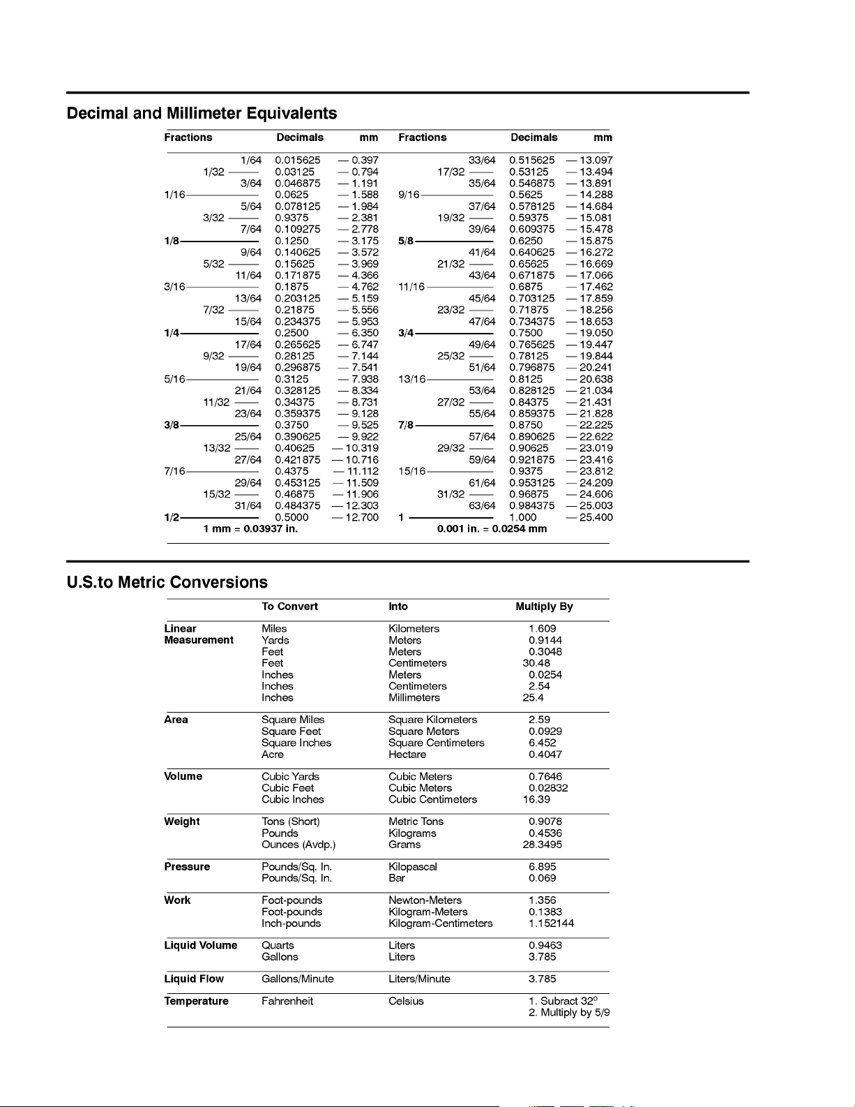
Equivalents and Conversions
Product Records and Maintenance
Page 2 – 2
Hydroject 3010
Page 11
Torque Specifications
Recommended fastener torque values are listed in the
following tables. For critical applications, as determined
by Toro, either the recommended torque or a torque that
is unique to the application is clearly identified and spe
cified in this Service Manual.
These Torque Specifications for the installation and
tightening of fasteners shall apply to all fasteners which
do not have a specific requirement identified in this Ser
vice Manual. The following factors shall be considered
when applying torque: cleanliness of the fastener, use
of a thread sealant (e.g. Loctite), degree of lubrication
on the fastener, presence of a prevailing torque feature,
hardness of the surface underneath the fastener’s head
or similar condition which affects the installation.
-
-
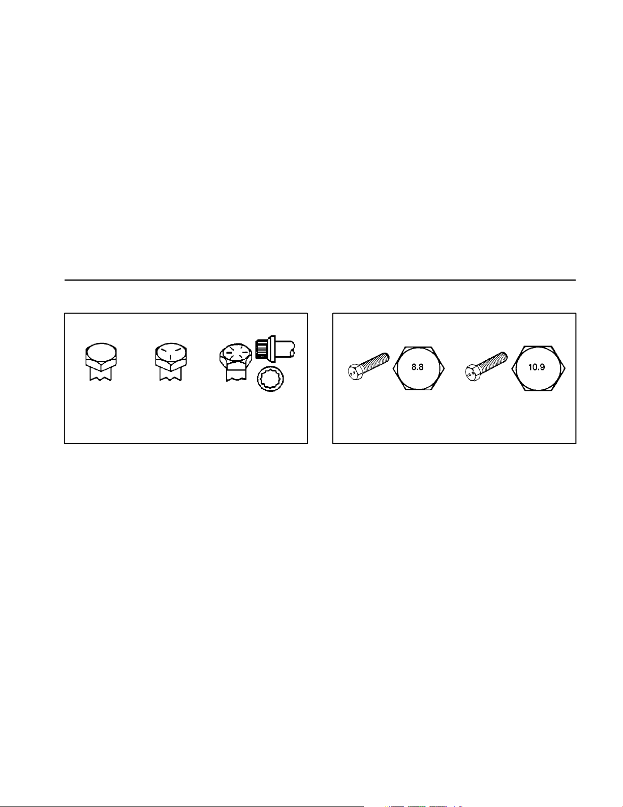
Fastener Identification
As noted in the following tables, torque values should be
reduced by 25% for lubricated fasteners to achieve
the similar stress as a dry fastener. Torque values may
also have to be reduced when the fastener is threaded
into aluminum or brass. The specific torque value
should be determined based on the aluminum or brass
material strength, fastener size, length of thread en
gagement, etc.
The standard method of verifying torque shall be performed by marking a line on the fastener (head or nut)
and mating part, then back off fastener 1/4 of a turn.
Measure the torque required to tighten the fastener until
the lines match up.
-
Grade 1
Grade 5 Grade 8
Inch Series Bolts and Screws
Figure 1
Class 8.8 Class 10.9
Metric Bolts and Screws
Figure 2
Hydroject 3010
Page 2 – 3
Product Records and Maintenance
Page 12

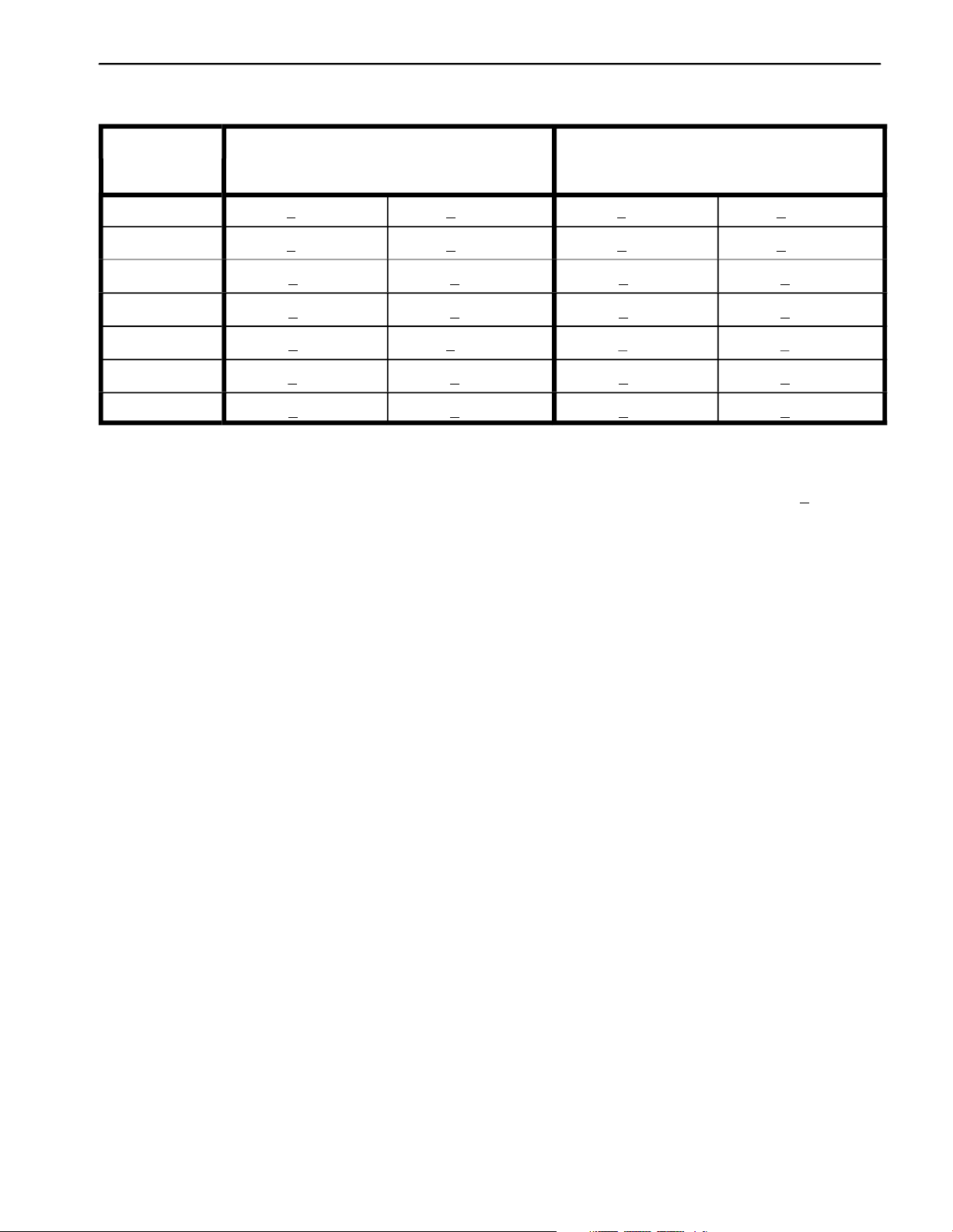
Standard Torque for Dry, Zinc Plated and Steel Fasteners (Inch Series)
Grade 1, 5 &
Thread Size
# 6 – 32 UNC 15 + 2 170 + 20 23 + 2 260 + 20
# 6 – 40 UNF
# 8 – 32 UNC 29 + 3 330 + 30 41 + 4 460 + 45
# 8 – 36 UNF
# 10 – 24 UNC 42 + 4 475 + 45 60 + 6 675 + 70
# 10 – 32 UNF
1/4 – 20 UNC 48 + 7 53 + 7 599 + 79 100 + 10 100 140 + 15 1580 + 170
1/4 – 28 UNF 53 + 7 65 + 10 734 + 10 1300 + 100 160 + 15 1800 + 170
5/16 – 18 UNC 15 105 + 17 169 200 + 25 2250 + 280 300 + 30 3390 + 340
5/16 – 24 UNF 138 + 17 128 + 17 1446 + 192 225 + 25 2540 + 280 325 + 30 3670 + 340
3/8 – 16 UNC 16 + 2 16 + 2 22 + 3 30 + 3 41 + 4 43 + 4 58 + 5
8 with Thin
Height Nuts
in–lb in–lb N–cm in–lb N–cm in–lb N–cm
10 + 2 13 + 2 147 + 23
13 + 2 25 + 5 282 + 30
18 + 2 30 + 5 339 + 56
115 + 1186 +
ft–lb ft–lb N–m ft–lb N–m ft–lb N–m
SAE Grade 1 Bolts, Screws, Studs &
Sems with Regular Height Nuts
(SAE J995 Grade 2 or Stronger Nuts)
113 115 +
SAE Grade 5 Bolts, Screws, Studs &
Sems with Regular Height Nuts
(SAE J995 Grade 2 or Stronger Nuts)
17 + 2 190 + 20 25 + 2 280 + 20
31 + 3 350 + 30 43 + 4 485 + 45
48 + 4 540 + 45 68 + 6 765 + 70
1125 +
SAE Grade 8 Bolts, Screws, Studs &
Sems with Regular Height Nuts
(SAE J995 Grade 5 or Stronger Nuts)
3/8 – 24 UNF 17 + 2 18 + 2 24 + 3 35 + 3 47 + 4 50 + 4 68 + 5
7/16 – 14 UNC 27 + 3 27 + 3 37 + 4 50 + 5 68 + 7 70 + 7 95 + 9
7/16 – 20 UNF 29 + 3 29 + 3 39 + 4 55 + 5 75 + 7 77 + 7 104 + 9
1/2 – 13 UNC 30 + 3 48 + 7 65 + 9 75 + 8 102 + 11 105 + 10 142 + 14
1/2 – 20 UNF 32 + 3 53 + 7 72 + 9 85 + 8 11 120 + 10 163 + 14
5/8 – 11 UNC 119 +
5/8 – 18 UNF 75 + 10 95 + 15 129 + 20 170 + 15 230 + 20 240 + 20 325 + 27
3/4 – 10 UNC 93 + 12 140 + 20 190 + 27 265 + 25 359 + 34 375 + 35 508 + 47
3/4 – 16 UNF 15 165 + 25 224 + 34 300 + 25 407 + 34 420 + 35 569 + 47
7/8 – 9 UNC 140 + 20 225 + 25 305 + 34 430 + 45 583 + 61 600 + 60 813 + 81
7/8 – 14 UNF 155 + 25 260 + 30 353 + 41 475 + 45 644 + 61 660 + 60 895 + 81
NOTE: Reduce torque values listed in the table above
by 25% for lubricated fasteners. Lubricated fasteners
are defined as threads coated with a lubricant such as
oil, graphite or thread sealant such as Loctite.
65 + 10 88 + 12 16 150 + 15 203 + 20 210 + 20 285 + 27
115 +
NOTE: The nominal torque values listed above for
Grade 5 and 8 fasteners are based on 75% of the mini
mum proof load specified in SAE J429. The tolerance is
approximately +
115 +
10% of the nominal torque value. Thin
height nuts include jam nuts.
NOTE: Torque values may have to be reduced when
installing fasteners into threaded aluminum or brass.
The specific torque value should be determined based
on the fastener size, the aluminum or base material
strength, length of thread engagement, etc.
-
Product Records and Maintenance
Page 2 – 4
Hydroject 3010
Page 13
Standard Torque for Dry, Zinc Plated and Steel Fasteners (Metric Fasteners)
Class 8.8 Bolts, Screws and Studs with Class 10.9 Bolts, Screws and Studs with
Thread Size Regular Height Nuts
(Class 8 or Stronger Nuts)
M5 X 0.8 57 + 5 in–lb 640 + 60 N–cm 78 + 7 in–lb 885 + 80 N–cm
M6 X 1.0 96 + 9 in–lb 1018 + 100 N–cm 133 + 13 in–lb 1500 + 150 N–cm
M8 X 1.25 19 + 2 ft–lb 26 + 3 N–m 27 + 2 ft–lb 36 + 3 N–m
M10 X 1.5 38 + 4 ft–lb 52 + 5 N–m 53 + 5 ft–lb 72 + 7 N–m
Regular Height Nuts
(Class 10 or Stronger Nuts)
M12 X 1.75 66 + 7 ft–lb 90 + 10 N–m 9 ft–lb 12 N–m
M16 X 2.0 15 ft–lb 225 + 20 N–m 229 + 22 ft–lb 310 + 30 N–m
M20 X 2.5 325 + 33 ft–lb 440 + 45 N–m 450 + 37 ft–lb 610 + 50 N–m
NOTE: Reduce torque values listed in the table above
by 25% for lubricated fasteners. Lubricated fasteners
are defined as threads coated with a lubricant such as
oil, graphite or thread sealant such as Loctite.
NOTE: Torque values may have to be reduced when
installing fasteners into threaded aluminum or brass.
The specific torque value should be determined based
on the fastener size, the aluminum or base material
strength, length of thread engagement, etc.
166 +
NOTE: The nominal torque values listed above are
based on 75% of the minimum proof load specified in
SAE J1199. The tolerance is approximately +
nominal torque value.
92 + 125 +
10% of the
Hydroject 3010
Page 2 – 5
Product Records and Maintenance
Page 14
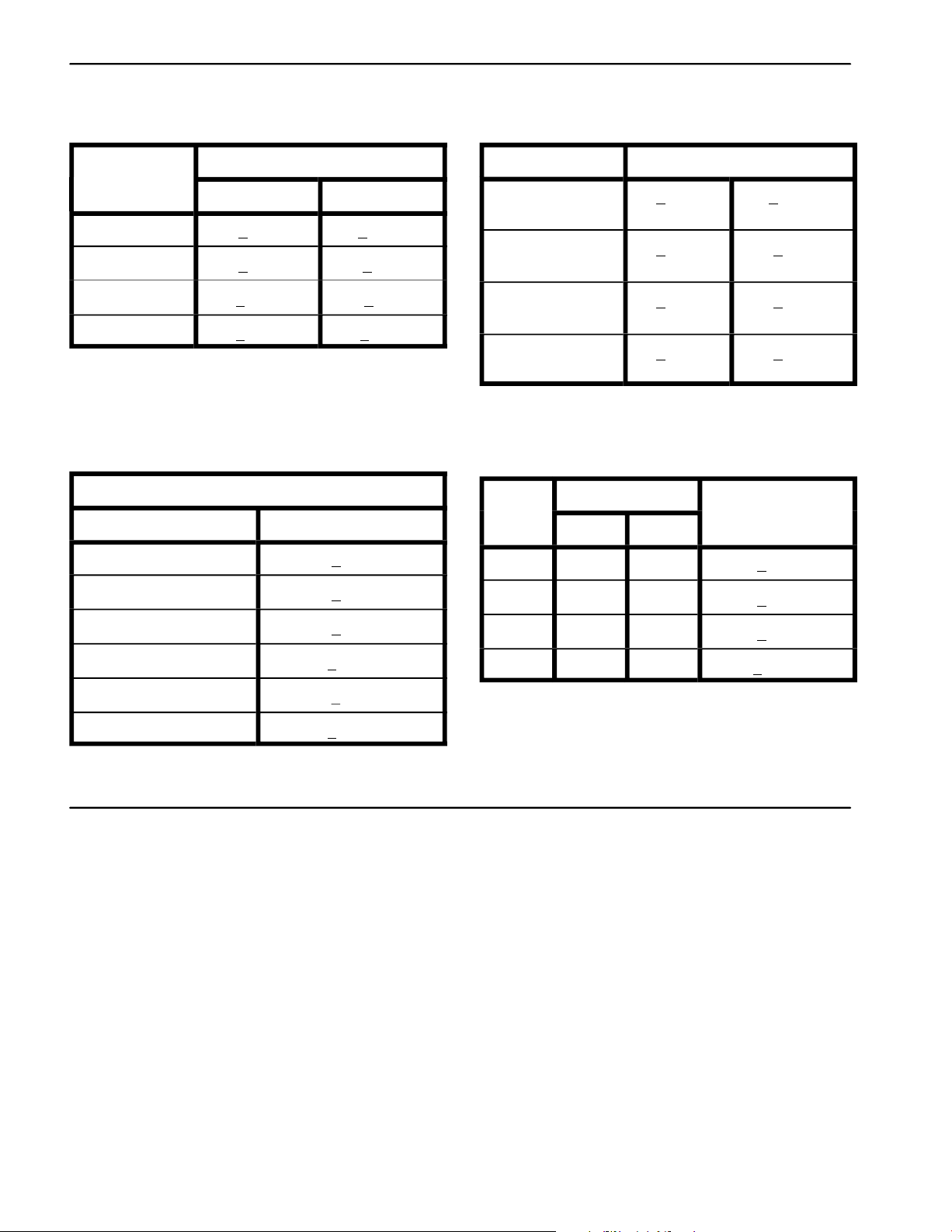
Other Torque Specifications
SAE Grade 8 Steel Set Screws Wheel Bolts and Lug Nuts
Recommended Torque
Thread Size
Square Head Hex Socket
1/4 – 20 UNC 140 + 20 in–lb 73 + 12 in–lb
5/16 – 18 UNC 215 + 35 in–lb 145 + 20 in–lb
3/8 – 16 UNC 35 + 10 ft–lb 18 + 3 ft–lb
1/2 – 13 UNC 75 + 15 ft–lb 50 + 10 ft–lb
Thread Cutting Screws
(Zinc Plated Steel)
Type 1, Type 23 or Type F
Thread Size
No. 6 – 32 UNC 20 + 5 in–lb
No. 8 – 32 UNC 30 + 5 in–lb
Baseline Torque*
Thread Size
7/16 – 20 UNF
Grade 5
1/2 – 20 UNF
Grade 5
M12 X 1.25
Class 8.8
M12 X 1.5
Class 8.8
** For steel wheels and non–lubricated fasteners.
Thread Cutting Screws
(Zinc Plated Steel)
Thread
Size
No. 6 18 20 20 + 5 in–lb
No. 8 15 18 30 + 5 in–lb
Threads per Inch
Type A Type B
Recommended Torque**
65 + 10 ft–lb 88 + 14 N–m
80 + 10 ft–lb 108 + 14 N–m
80 + 10 ft–lb 108 + 14 N–m
80 + 10 ft–lb 108 + 14 N–m
Baseline Torque*
No. 10 – 24 UNC 38 + 7 in–lb
1/4 – 20 UNC 85 + 15 in–lb
5/16 – 18 UNC 20 in–lb
3/8 – 16 UNC 200 + 100 in–lb
110 +
Conversion Factors
in–lb X 11.2985 = N–cm N–cm X 0.08851 = in–lb
ft–lb X 1.3558 = N–m N–m X 0.7376 = ft–lb
No. 10 12 16 38 + 7 in–lb
No. 12 11 14 85 + 15 in–lb
* Hole size, material strength, material thickness & finish
must be considered when determining specific torque
values. All torque values are based on non–lubricated
fasteners.
Product Records and Maintenance
Page 2 – 6
Hydroject 3010
Page 15

7DEOHRI&RQWHQWV
,1752'8&7,21
63(&,),&$7,216
6(59,&($1'5(3$,56
(QJLQH5HPRYDODQG,QVWDOODWLRQ
.2+/(5(1*,1(6(59,&(0$18$/
&KDSWHU
.RKOHU(QJLQH
+\GURMHFW 3DJH² .RKOHU(QJLQH
Page 16

,QWURGXFWLRQ
7KLV&KDSWHUJLYHVLQIRUPDWLRQDERXWVSHFLILFDWLRQVDQG
UHSDLURIWKH.RKOHUHQJLQHXVHGLQWKH3UR&RUH
*HQHUDOHQJLQHPDLQWHQDQFHSURFHGXUHVDUHGHVFULEHG
LQ\RXU2SHUDWRU·V0DQXDO,QIRUPDWLRQRQHQJLQHWURX
EOHVKRRWLQJ WHVWLQJ GLVDVVHPEO\ DQG UHDVVHPEO\ LV
LGHQWLILHGLQWKH.RKOHU(QJLQH6HUYLFH0DQXDOWKDWLVLQ
FOXGHGDWWKHHQGRIWKLVVHFWLRQ
0RVWUHSDLUVDQGDGMXVWPHQWVUHTXLUH WRROVZKLFKDUH
FRPPRQO\ DYDLODEOH LQ PDQ\ VHUYLFH VKRSV 6SHFLDO
WRROVDUHGHVFULEHGLQWKH.RKOHU(QJLQH6HUYLFH0DQX
DO7KHXVHRIVRPHVSHFLDOL]HGWHVWHTXLSPHQWLVH[
SODLQHG+RZHYHUWKHFRVWRIWKHWHVWHTXLSPHQWDQGWKH
VSHFLDOL]HGQDWXUHRIVRPHUHSDLUVPD\GLFWDWHWKDWWKH
ZRUNEHGRQHDWDQHQJLQHUHSDLUIDFLOLW\
6HUYLFHDQGUHSDLUSDUWVIRU.RKOHUHQJLQHVDUHVXSSOLHG
WKURXJK\RXUORFDO.RKOHUGHDOHURUGLVWULEXWRU
.RKOHU(QJLQH
3DJH²
+\GURMHFW
Page 17

6SHFLILFDWLRQV
,WHP 'HVFULSWLRQ
0DNH'HVLJQDWLRQ .RKOHU&RPPDQG3UR&DUE²VWURNH9²7ZLQ
1XPEHURI&\OLQGHUV
%RUH[6WURNH µ[µPP[PP
7RWDO'LVSODFHPHQW &XELF,QFKHVFF
&RPSUHVVLRQ5DWLR
'U\:HLJKWDSSUR[LPDWH 3RXQGV.LORJUDPV
)XHO 8QOHDGHG5HJXODU*DVROLQH0LQLPXP2FWDQH
)XHO7DQN&DSDFLW\ 86*DOORQV/LWHUV
*RYHUQRU 0HFKDQLFDO
,GOH6SHHGQRORDG ²530
+LJK,GOHQRORDG ²530
(QJLQH2LO 6HH2SHUDWRU·V0DQXDO
2LO3XPS *HDUGULYHQWURFKRLGW\SH
$LU&RROHG2+9
&UDQNFDVH2LO&DSDFLW\ 864XDUW/LWHUVZLWKILOWHU
6WDUWHU 9'&
+\GURMHFW 3DJH² .RKOHU(QJLQH
Page 18
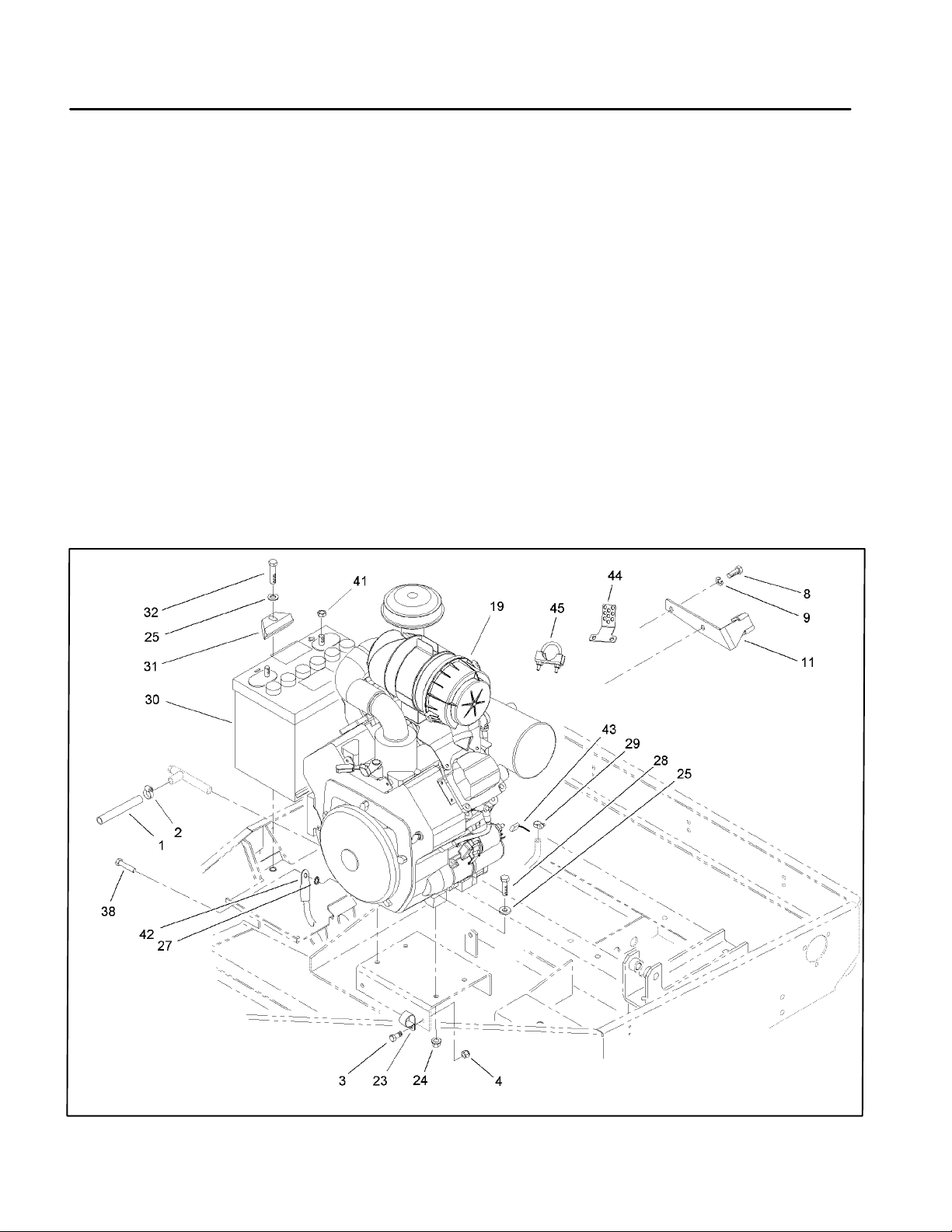
6HUYLFHDQG5HSDLUV
(QJLQH5HPRYDODQG,QVWDOODWLRQ
3DUNWKHPDFKLQHRQDOHYHOVXUIDFHHQJDJHWKHSDUN
LQJEUDNHDQGUHPRYHWKHKRRG
'LVFRQQHFW ERWK WKH SRVLWLYH DQG QHJDWLYH ²
FDEOHVIURPWKHEDWWHU\/RRVHQWKHEDWWHU\FODPS,WHP
DQGUHPRYHWKHEDWWHU\
'UDLQWKHRLOIURPWKHHQJLQHLQWRDVXLWDEOHFRQWDLQHU
'LVFRQQHFWWKHGULYHFRXSOLQJIURPWKHFOXWFKDGDSWHU
VHH'ULYH&RXSOLQJ5HPRYDODQG,QVWDOODWLRQLQ:DWHU
6\VWHP6HUYLFH
5HPRYH WKH ZDWHU SXPS GULYH EHOW DQG K\GUDXOLF
SXPSGULYHEHOW
'LVFRQQHFWWKHHQJLQHZLULQJKDUQHVVFRQQHFWRU'LV
FRQQHFWDQGSOXJWKHIXHOKRVH
5HPRYHIRXUQXWV,WHPFDSVFUHZV,WHPDQG
ZDVKHUV,WHPVHFXULQJWKHHQJLQHWRWKHIUDPH
$WWDFK DQ HQJLQH OLIWLQJ FKDLQ WR WKH HQJLQH OLIWLQJ
VWUDSV&RQQHFWWKHFKDLQWRDKRLVWRUEORFNDQGWDFNOH
DQGUHPRYHVODFNIURPWKHFKDLQDQGOLIWLQJGHYLFH2QH
SHUVRQVKRXOGRSHUDWHWKHKRLVWRUEORFNDQGWDFNOHDQG
WKHRWKHUSHUVRQVKRXOGKHOSJXLGHWKHHQJLQHRXWRIWKH
IUDPH5HPRYHWKHHQJLQHIURPWKHIUDPH
0RXQWWKHHQJLQHLQDQHQJLQHUHEXLOGLQJVWDQGRUSXW
LWRQDVWXUG\ZRUNEHQFK%HIRUHGLVDVVHPEOLQJWKHHQ
JLQHUHPRYHH[WHUQDODFFHVVRULHVVXFKDVWKHPXIIOHU
DLU FOHDQHU K\GUDXOLF SXPS FOXWFK K\GUDXOLF SXPS
SXOOH\ ZDWHU SXPS FOXWFK DQG FOXWFK NH\ VHH 'ULYH
&RXSOLQJ 5HPRYDO DQG ,QVWDOODWLRQ LQ :DWHU 6\VWHP
6HUYLFH
7RLQVWDOOWKHHQJLQHSHUIRUPVWHSV²LQUHYHUVH
RUGHU
5HSODFHWKHRLOILOWHUDQGILOOWKHHQJLQHZLWKWKHFRU
UHFWRLO
.RKOHU(QJLQH
)LJXUH
3DJH²
+\GURMHFW
Page 19

Table of Contents
Chapter 4
Hydraulic System
SPECIFICATIONS . . . . . . . . . . . . . . . . . . . . . . . . . . 2
GENERAL INFORMATION . . . . . . . . . . . . . . . . . . . 3
Hydraulic Hose and Fitting Information . . . . . . . . 3
Pushing or Towing . . . . . . . . . . . . . . . . . . . . . . . . 5
HYDRAULIC DIAGRAM . . . . . . . . . . . . . . . . . . . . . . 6
SPECIAL TOOLS . . . . . . . . . . . . . . . . . . . . . . . . . . . 7
Hydraulic Tester. . . . . . . . . . . . . . . . . . . . . . . . . . 7
TROUBLESHOOTING . . . . . . . . . . . . . . . . . . . . . . . 8
Transmission Operates in One Direction Only . . 8
System Operates Hot, Looses Power or
Will Not Operate in Either Direction
TESTING . . . . . . . . . . . . . . . . . . . . . . . . . . . . . . . . . 9
Hydraulic Tests . . . . . . . . . . . . . . . . . . . . . . . . . 10
ADJUSTMENTS . . . . . . . . . . . . . . . . . . . . . . . . . . . . 11
Traction Cable Adjustment . . . . . . . . . . . . . . . . . 11
. . . . . . . . . 8
Speed Control Adjustment. . . . . . . . . . . . . . . . . 11
Transmission Neutral Adjustment . . . . . . . . . . . 12
Aeration Speed Adjustment . . . . . . . . . . . . . . . . 12
Pump Drive Belt Adjustment . . . . . . . . . . . . . . . 13
REPAIRS . . . . . . . . . . . . . . . . . . . . . . . . . . . . . . . . 14
Pump Drive Belt Replacement . . . . . . . . . . . . . 14
Hydraulic Pump Removal and Installation. . . . . 15
Pump Shaft Seal Replacement . . . . . . . . . . . . 16
Pump Charge Check Valve Service . . . . . . . . . 17
Pump Bypass Valve Service . . . . . . . . . . . . . . . 17
Charge Pump Service . . . . . . . . . . . . . . . . . . . . 18
Major Pump Repair . . . . . . . . . . . . . . . . . . . . . . 18
Wheel Motor Removal and Installation . . . . . . . 22
Wheel Motor Repair. . . . . . . . . . . . . . . . . . . . . . 23
Hydroject 3010 Page 4 - 1 Table of Contents
Page 20

Specifications
Item Description
__________________________________________________________________________________________
Pump
Rated system pressure 2100 PSI maximum, 1000 PSI continuous
Rated system flow 8.5 GPM maximum at 3500 RPM
Charge relief pressure 25 to 70 PSI psi at 3500 RPM
Oil filter
________________________________________________________________________________________________________________________________________________________
Wheel Motor Orbit rotor type
________________________________________________________________________________________________________________________________________________________
Hydraulic Oil
________________________________________________________________________________________________________________________________________________________
Reservoir (gear case) Approximately 4 - 5 quarts
Sundstrand Series 70, BDP-10L Variable Displacement Pump
25 micron screw-on type. No by-pass
See Operator’s Manual
Specifications Page 4 - 2 Hydroject 3010
Page 21
General Information
Hydraulic Hoses
Hydraulic hoses are subject to extreme conditions such
as, pressure differentials during operation and exposure
to weather, sun, chemicals, very warm storage conditions or mishandling during operation or maintenance.
These conditions can cause damage or premature deterioration. Some hoses, such as reel motor hoses, are
more susceptible to these conditions than others. Inspect the hoses frequently for signs of deterioration or
damage.
When replacing a hydraulic hose, be sure that the hose
is straight (not twisted) before tightening the fittings. This
can be done by observing the imprint on the hose. Use
two wrenches; one to hold the hose straight and one to
tighten the hose swivel nut onto the fitting.
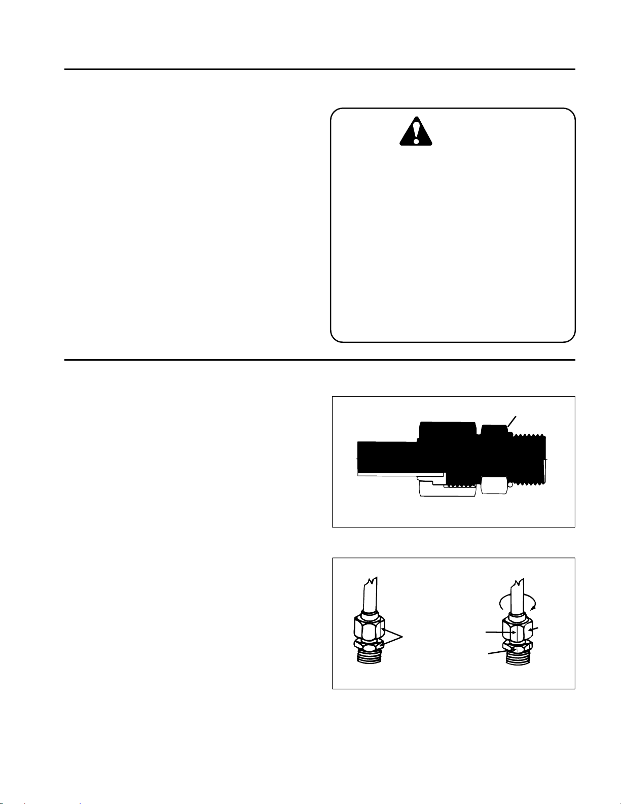
CAUTION
Before disconnecting or performing any work
on the hydraulic system, all pressure in the
system must be relieved by stopping the engine and opening the bypass valve.
Keep body and hands away from pin hole
leaks or nozzles that eject hydraulic fluid under high pressure. Use cardboard,
not hands, to search for leaks. Hydraulic fluid
escaping under pressure can have sufficient
force to penetrate the skin and do serious
damage. If fluid is injected into the skin, it
must be surgically removed within a few
hours by a doctor familiar
injury or gangrene may result.
paper or
with this
type of
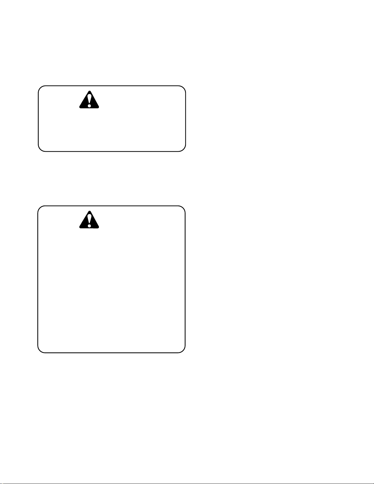
Hydraulic Fitting Installation
O-Ring Face Seal (Fig. 2, 3)
1. Make sure both threads and sealing surfaces are free
of burrs, nicks, scratches, or any foreign material.
2. Make sure the O-ring is installed and properly seated
in the groove. It is recommended that the O-ring be
replaced any time the connection is opened.
3. Lubricate the O-ring with a light coating of oil.
4. Put the tube and nut squarely into position on the face
seal end of the fitting and tighten the nut until finger tight.
5. Mark the nut and fitting body. Hold the body with a
wrench. Use another wrench to tighten the nut to the
correct flats from finger tight (F .F.F .T.). The markings on
the nut and fitting body will verify that the connection has
been tightened.
Size F.F.F.T.
4 (1/4 in. nominal hose or tubing) .75 r .25
6 (3/8 in.) r .25
8 (1/2 in.) .75 r .25
10 (5/8 in.) r .25
12 (3/4 in.) r .25
16 (1 in.) .75 r .25
.75
1.00
.75
Nut
Sleeve
Seal
Body
Figure 2
Mark Nut
and Body
Finger Tight After Proper Tightening
Final
Position
Extend Line
Initial
Position
Figure 3
Hydroject 3010 Page 4 - 3 General Information
Page 22
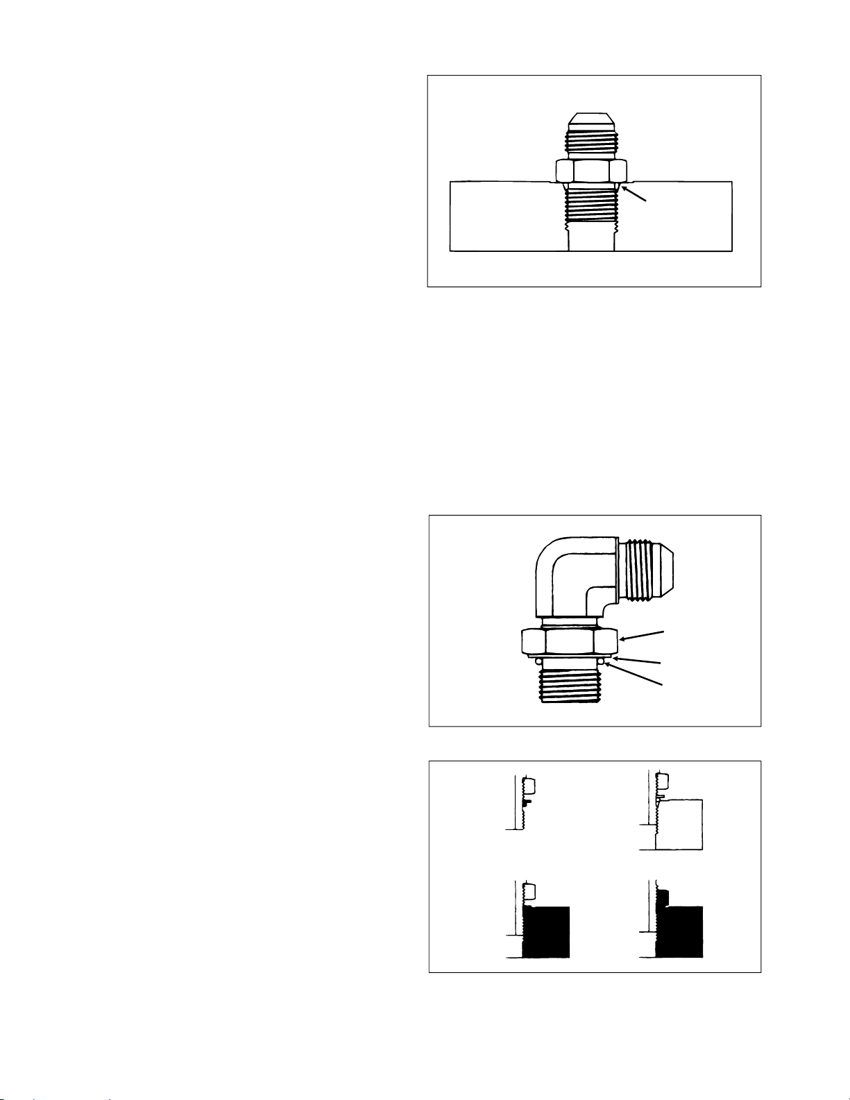
SAE Straight Thread O-Ring Port - Non-adjustable
(Fig. 4)
1. Make sure both threads and sealing surfaces are free
of burrs, nicks, scratches, or any foreign material.
2. Always replace the O-ring seal when this type of fitting
shows signs of leakage.
3. Lubricate the O-ring with a light coating of oil.
4. Install the fitting into the port and tighten it down full
length until finger tight.
5. Tighten the fitting to the correct flats from finger tight
(F.F.F.T.).
Size F.F.F.T.
4 (1/4 in. nominal hose or tubing) 1.00 r .25
6 (3/8 in.) 1.50 r .25
8 (1/2 in.) 1.50 r .25
10 (5/8 in.) 1.50 r .25
12 (3/4 in.) 1.50 r .25
16 (1 in.) 1.50 r .25
SAE Straight Thread O-Ring Port - Adjustable
(Fig. 5, 6)
1. Make sure both threads and sealing surfaces are free
of burrs, nicks, scratches, or any foreign material.
2. Always replace the O-ring seal when this type of fitting
shows signs of leakage.
3. Lubricate the O-ring with a light coating of oil.
4. Turn back the jam nut as far as possible. Make sure
the back up washer is not loose and is pushed up as far
as possible (Step 1).
O-Ring
Figure 4
Lock Nut
Back-Up Washer
O-Ring
5. Install the fitting into the port and tighten finger tight
Figure 5
until the washer contacts the face of the port (Step 2).
6. T o put the fitting in the desired position, unscrew it by
the required amount, but no more than one full turn
Step 1
Step 3
(Step 3).
7. Hold the fitting in the desired position with a wrench
and turn the jam nut with another wrench to the correct
flats from finger tight (F.F.F.T.) (Step 4)
Size F.F.F.T.
4 (1/4 in. nominal hose or tubing) 1.00 r .25
6 (3/8 in.) 1.50 r .25
8 (1/2 in.) 1.50 r .25
10 (5/8 in.) 1.50 r .25
12 (3/4 in.) 1.50 r .25
16 (1 in.) 1.50 r .25
Step 2
Step 4
Figure 6
General Information Page 4 - 4 Hydroject 3010
Page 23
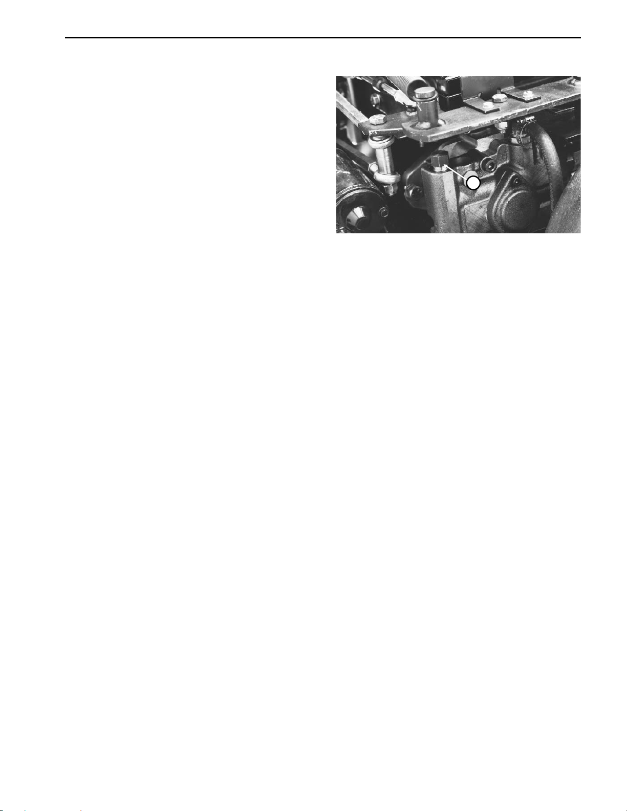
Pushing or Towing (Fig. 7)
The machine can be pushed or towed for very short
distances with the engine off, if necessary.
IMPORT ANT: Do not push or tow the machine faster
than 5 MPH because the hydraulic pump may be
damaged. If the machine must be moved further
than a few feet, transport it on a trailer or pull with
traction wheel raised and secured to a dolly . Whenever the machine is pushed or towed, the by-pass
valve must be open. Hook on front of handle is used
for a tie-down only, not a hitch point.
1. Stop the engine and raise the hood.
1
2. Open the by-pass valve by turning it counterclockwise
(2 turns maximum).
3. After moving the machine, close the by-pass valve by
turning it clockwise. Tighten the by-pass valve to a
torque of 7 to 10 ft-lb.
IMPORTANT: Operating the machine with the bypass valve open will cause improper operation and
overheating of the hydraulic system.
Figure 7
1. By-pass valve
Hydroject 3010 Page 4 - 5 General Information
Page 24
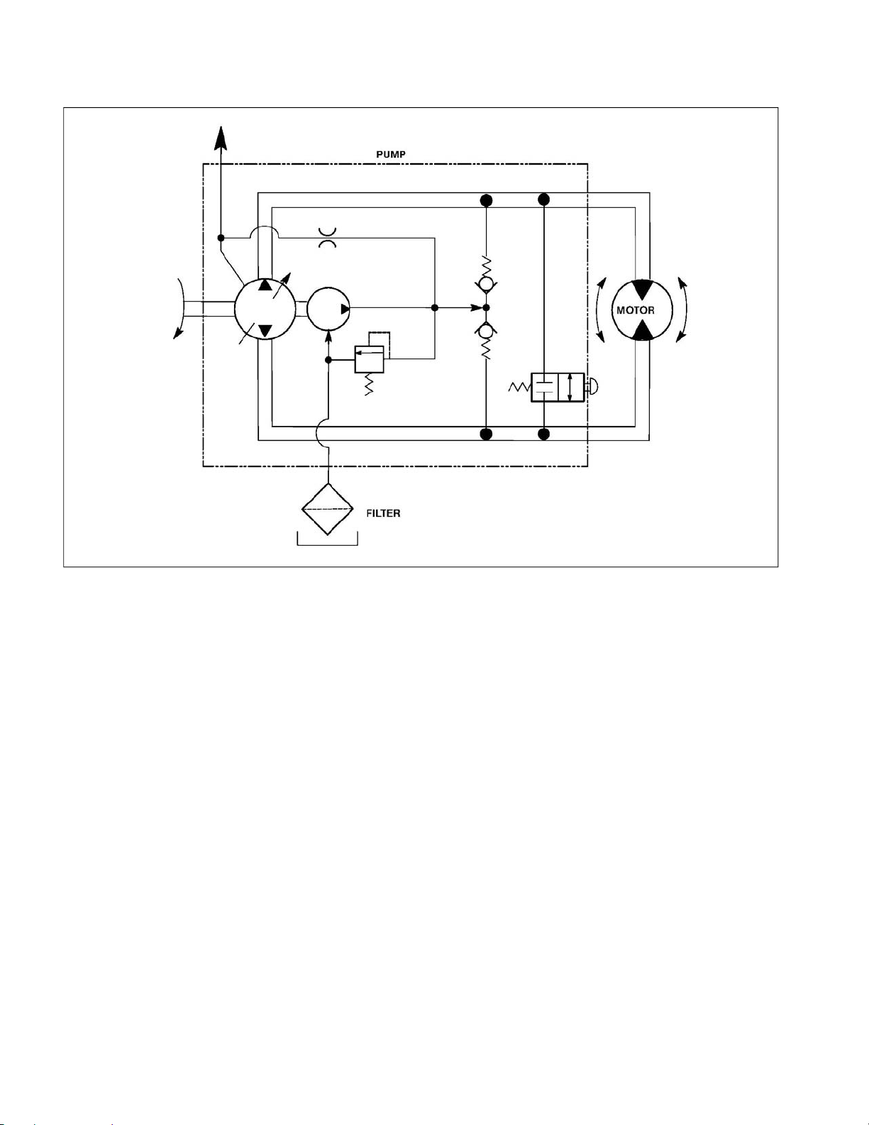
Hydraulic Diagram
Cooling
Orifice
Input
(Belt Drive)
Variable
Disp. Pump
Inlet
Filter
Charge
Pump
Reservoir
(Gear Case)
Charge Relief
Val
ve
Figure 8
Charge
Check
ves
Val
By-pass
ve
Val
Wheel
Motor
Hydraulic Diagram Page 4 - 6 Hydroject 3010
Page 25
Special Tools
NOTE: Order special tools from the TORO SPECIAL
TOOLS AND APPLICATIONS GUIDE (COMMERCIAL
PRODUCTS). Some tools may be listed in the
Hydroject 3010 Parts Catalog. Some tools may also be
available from a local supplier.
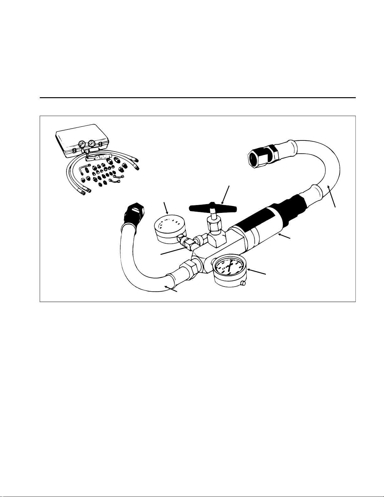
Hydraulic Tester - With Pressure and Flow Capabilities (Fig. 9)
Load Valve
Low Pressure
Gauge
Outlet
Hose
Gauge
Protector Valve
Inlet Hose
Figure 9
You must have o-ring face seal (ORFS) adapter fittings
for this tester to use it on the HydroJect 3010.
1. INLET HOSE: Hose connected from the system
circuit to the inlet side of the hydraulic tester.
2. LOAD VALVE: If required, upon turning the valve to
restrict flow, a simulated working load is created in the
circuit.
3. LOW PRESSURE GAUGE: Low range gauge to
provide accurate reading at low pressure, 0 - 1000 psi.
This gauge has a protector valve which cuts out
when pressure is about to exceed the normal range
for the gauge. The cutout pressure is adjustable.
Flow Meter
High Pressure
Gauge
4. HIGH PRESSURE GAUGE: High range gauge to
accommodate pressure beyond the capacity of the low
pressure gauge, 0 - 5000.
5. FLOW METER: This meter measures actual oil flow
in the operation circuit, with a gauge rated at 15 GPM.
6. OUTLET HOSE: Hose from the outlet side of the
hydraulic tester to be connected to the hydraulic system
circuit.
Hydroject 3010 Page 4 - 7 Special Tools
Page 26

Troubleshooting
The cause of an improperly functioning hydraulic system is best diagnosed with the use of proper testing
system could lead to extensive internal component
damage.
equipment and a thorough understanding of the complete hydraulic system.
The charts that follow contain detailed information to
assist in troubleshooting. There may possibly be more
A hydraulic system with an excessive increase in heat
or noise is a potential failure. Should either of these
conditions be noticed, immediately stop the machine,
than one cause for a machine malfunction. All causes
should be checked in the order in which they are listed
on the charts.
turn off the engine, locate the cause of the trouble, and
correct it before allowing the machine to be used again.
Continued use of an improperly functioning hydraulic
Refer to the Testing section of this Chapter for precau-
tions and specific test procedures.
Tr ansmission Operates in One Direction Only
Cause Correction
__________________________________________________________________________________________
Faulty traction control linkage. Repair linkage
________________________________________________________________________________________________________________________________________________________
Transmission charge check valve defective. Inspect and clean or replace charge/check.
System Operates Hot, Looses Power or Will Not Operate in Either Direction
Cause Correction
__________________________________________________________________________________________
Faulty control linkage. Repair linkage
________________________________________________________________________________________________________________________________________________________
Parking brake engaged. Disengage parking brake.
________________________________________________________________________________________________________________________________________________________
Hydraulic oil level too low. Fill to proper level.
________________________________________________________________________________________________________________________________________________________
By-pass valve open. Close by-pass valve.
________________________________________________________________________________________________________________________________________________________
Clogged hydraulic filter. Replace filter.
________________________________________________________________________________________________________________________________________________________
Low charge pressure - Test A. Inspect charge relief valve and replace if faulty.
________________________________________________________________________________________________________________________________________________________
Low traction pump flow/pressure - Test B. Repair or replace pump.
________________________________________________________________________________________________________________________________________________________
Inspect charge pump and replace if faulty.
Low traction motor efficiency - Test C. Repair or replace traction motor.
Troubleshooting Page 4 - 8 Hydroject 3010
Page 27
Testing
The most effective method for isolating problems in the
hydraulic system is by using hydraulic test equipment
such as pressure gauges and flow meters in the circuits
during various operational checks. (See the Special
Tools section in this Chapter.)
CAUTION
Failure to use gauges with the recommended
pressure (psi) rating as listed in the test procedures could result in damage to the gauge
and possible personal injury from leaking hot
oil.
Before Performing Hydraulic Tests
All obvious areas such as oil supply, filter, binding
linkage, loose fasteners, or improper adjustments must
be checked before assuming that a hydraulic component is the source of the problem being experienced.
W ARNING
Before disconnecting or performing any work
on the hydraulic system, all pressure in the
system must be relieved by stopping the engine and opening the bypass valve.
Keep body and hands away from pin hole
leaks or nozzles that eject hydraulic fluid under high pressure. Use paper or cardboard,
not hands, to search for leaks. Hydraulic fluid
escaping under pressure can have sufficient
force to penetrate skin and do serious damage. If fluid is injected into the skin, it must be
surgically removed within a few hours by a
doctor familiar with this type of injury or gangrene may result.
1. Thoroughly clean the machine before disconnecting
or disassembling any hydraulic components. Always
keep in mind the need for cleanliness when working on
hydraulic equipment.
2. Put caps or plugs on any hydraulic lines left open or
exposed during testing or removal of components.
3. The engine must be in good operating condition. Use
a tachometer when making a hydraulic test. Engine
speed can affect the accuracy of the tester readings.
4. T o prevent damage to tester or components, the inlet
and the outlet hoses must be properly connected, and
not reversed (tester with pressure and flow capabilities).
5. T o minimize the possibility of damaging components,
completely open the load valve by turning it counterclockwise (tester with pressure and flow capabilities).
6. Install fittings finger tight, far enough to insure that
they are not cross-threaded, before tightening with a
wrench.
7. Position the tester hoses so that rotating machine
parts will not make contact with them and result in hose
or tester damage.
8. Check the oil level in the reservoir.
9. Check the control linkage for improper adjustment,
binding or broken parts.
10. All hydraulic tests should be made with the hydraulic
oil at normal operating temperature.
Hydroject 3010 Page 4 - 9 Testing
Page 28
Hydraulic Tests (Fig. 10, 11)
1. Make sure hydraulic oil is at normal operating temperature by operating the machine for approximately 10
minutes.
2. Engage parking brake and stop the engine. Make
sure parking brake is properly adjusted before performing hydraulic tests.
3. With engine off, disconnect hose from bulkhead fitting
and install tester in series between traction pump and
wheel motor. Make sure tester flow control valve is
OPEN.
IMPORTANT: Make sure that the oil flow indicator
arrow on the flow gauge is showing that oil will flow
from pump, through tester and to wheel motor.
T est A: Charge Pressure
4. Start the engine and move throttle to full engine RPM
(approx. 3500 RPM).
GAUGE READING: 25 to 70 PSI no load.
5. If there is no pressure, or pressure is low, inspect for
restriction in pump intake line and inlet filter. Inspect
charge relief valve and valve seat. Inspect for sheared
charge pump key. Disassemble charge pump and inspect for internal damage or worn parts. If charge pump
is in good condition (no scoring, scratches, or excessive
wear), piston pump and motor might be suspected of
wear and inefficiency, thus charge pump is unable to
keep up with internal leakage.
NOTE: At pressures above approximately 500 PSI,
mechanical override in handle will cause pump to begin
to de-stroke.
11. If you cannot get 7 GPM or 500 PSI, traction pump
may have internal damage or excessive wear.
TEST C: Traction Motor Efficiency
12. Lower drive wheel to ground and engage parking
brake. Block front and rear of all wheels. Chain machine
to an immovable object and remove slack from chain.
13. With tester flow control valve open, slowly move
traction handle (up or down) so flow is from the pump,
through the tester, then to the wheel motor. Move trac-
tion handle until maximum pressure is attained with
wheel not rotating and read flow gauge.
14. If flow reading is higher than 1.5 GPM, motor may
have internal damage or excessive wear.
1
2
TEST B: Traction Pump Flow
6. Lift the drive wheel off the ground using a jack. Block
front and rear of the other wheels. Make sure the tester
flow control valve is OPEN.
7. Start the engine and release the parking brake.
8. While watching flow and pressure gauges, move
traction handle (up or down) so flow is from the pump,
through the tester, then to the wheel motor. Move traction handle until 6 GPM is obtained.
9. If pressure is less than 200 to 300 PSI go to step 10.
If pressure is more than 200 to 300 PSI stop the engine
and inspect for binding parking brake. Inspect for restriction in lines to and from motor. If there are no restrictions,
motor should be suspected of having internal damage.
10. While watching flow and pressure gauges, move
traction handle (up or down) to full speed position so
flow is from the pump, through the tester, then to the
wheel motor. Slowly close flow control valve until you
get readings of 7 GPM and 500 PSI.
Figure 10
1. Hose 2. Bulkhead fitting
Variable Displacement Pump
Tes ter
Figure 11
Wheel
Motor
Testing Page 4 - 10 Hydroject 3010
Page 29
Adjustments
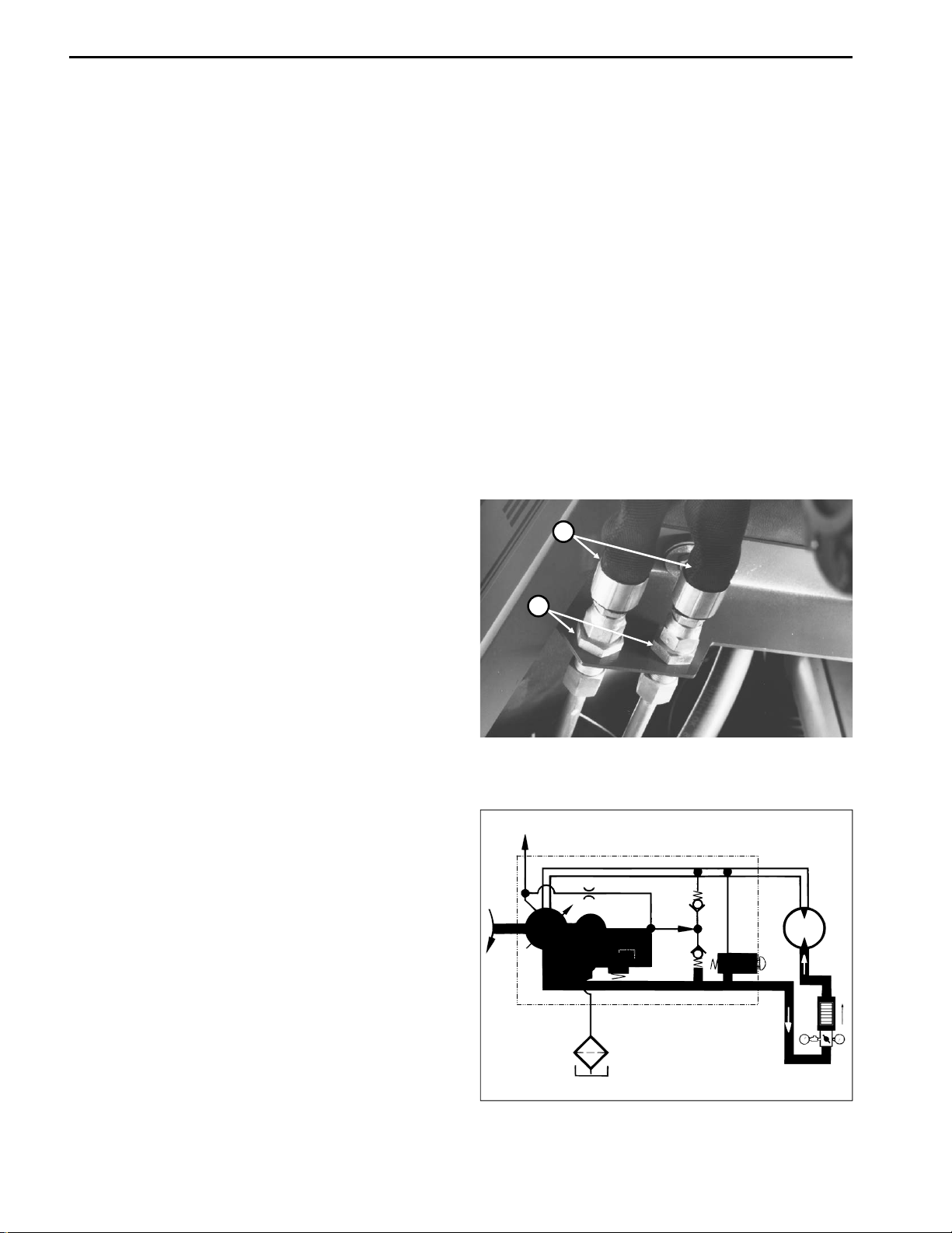
Tr action Cable Adjustment (Fig. 12)
1. Park machine on a level surface, stop the engine and
open the hood. Remove lower cover from handle.
2. Adjust pump end of push-pull cable with pump lever
in neutral starting position by adjusting jam nuts so
distance from seal to threads is 1.00 r 0.05 in.
3. Adjust jam nuts at tiller end of push-pull cable so
traction handle is centered on control handle.
Speed Control Adjustment (Fig. 13)
1. Park machine on a level surface, stop the engine and
open the hood.
2. Adjust speed control cable (Item 26) so speed stop
lever (Item 9) can move to horizontal position.
1
2
Figure 12
1. Jam nuts - pump end 2. Jam nuts - tiller end
3. Adjust speed rods (Item 14) so rod end mounting
holes in pivot arms (Items 11, 23) are located vertically
in line with pivot pin (Item 22).
24
1
2
28
30
29
27
28
26
3
7
25
4
5
6
17
16
8
9
24
8
10
8
11
12
19
20
19
14
13
8
23
15
15
13
19
21
18
20
8
22
18
Figure 13
Hydroject 3010 Page 4 - 11 Adjustments
Page 30
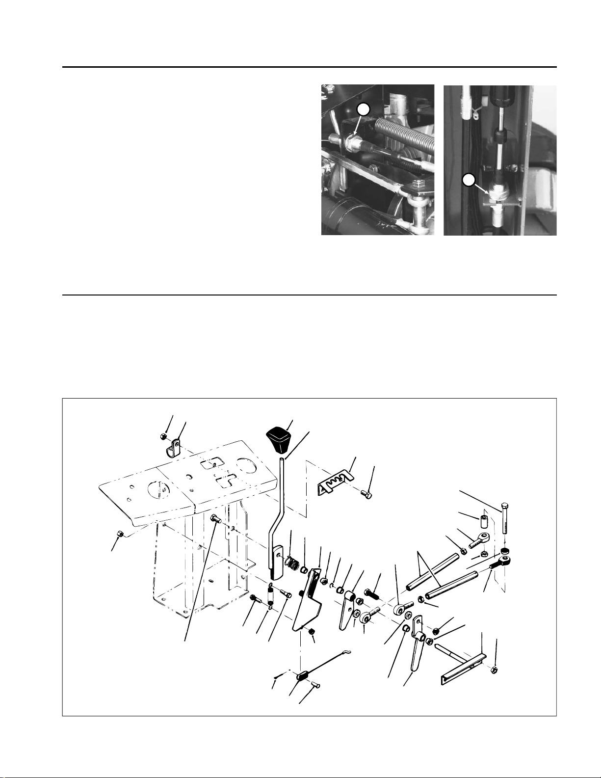
Tr ansmission Neutral Adjustment (Fig. 14)
If machine moves when lever is released, transmission
neutral adjustment is needed.
1. Park machine on a level surface, stop the engine and
open the hood.
2. Lift drive wheel off the ground using a jack. Block front
and rear of other wheels.
3. Start engine and release parking brake.
4. Slightly loosen locknut on top of neutral adjustment
cam and rotate cam hex until traction wheel stops
rotating. Tighten the locknut.
5. Move traction bail completely up and down. Release
handle and check for wheel rotation. If wheel continues
rotating, repeat step 4.
6. If problem continues, stop the engine, check linkage
for binding or damage, then do adjustment procedure
again.
7. Loosen two (2) screws and adjust switch tab so
switches are actuated when pump control is in neutral
and not actuated when pump control is stroked.
3
1
2
Figure 14
1. Neutral adjustment cam
2. Locknut
3. Switch tab
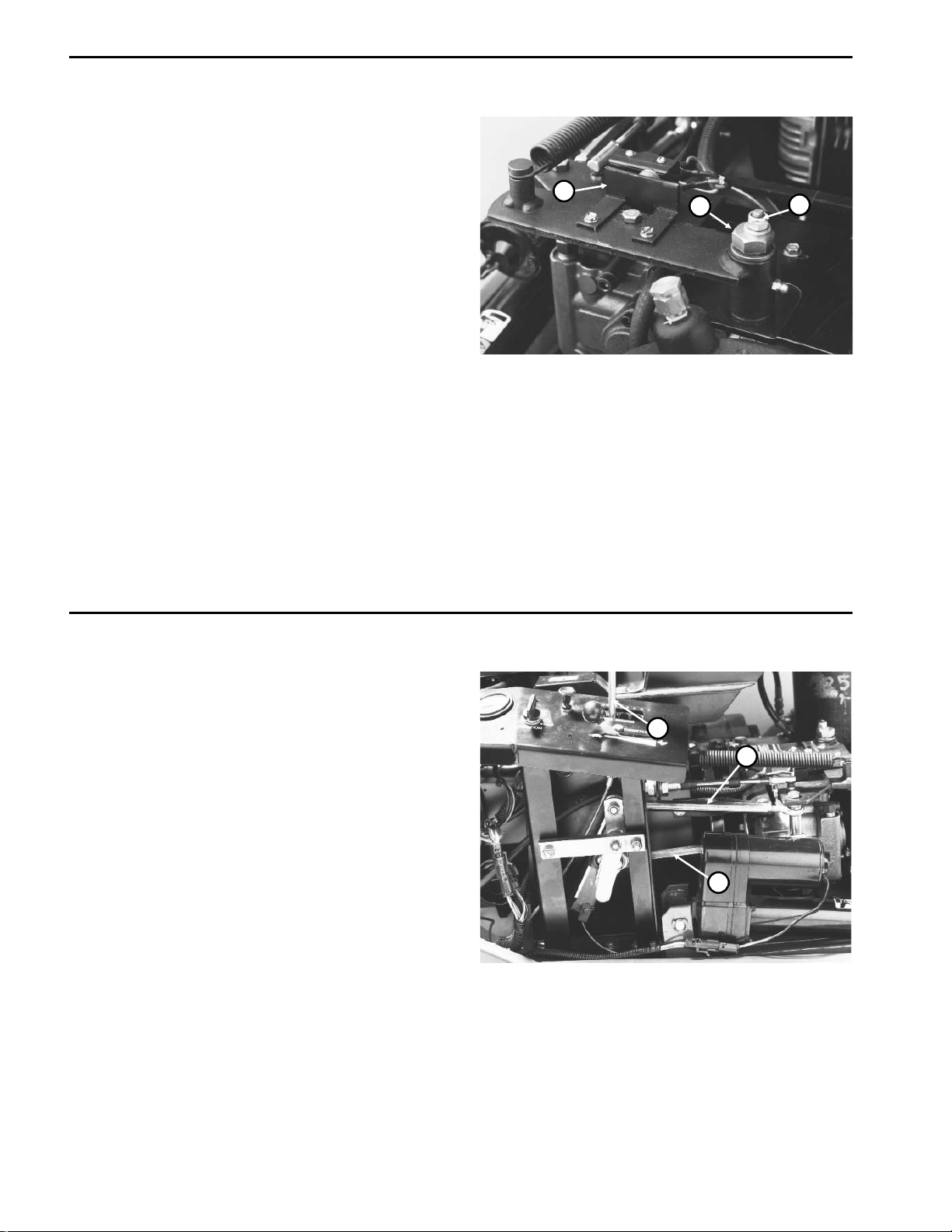
Aeration Speed Adjustment (Fig. 15)
1. Park machine on a level surface, stop the engine and
open the hood.
2. Put speed control lever into second slot from left
(while facing control panel).
3. Lower machine into aerate mode so transport wheels
are off the ground.
4. Lift drive wheel off ground using a jack.
5. Start the engine and release the parking brake.
6. Operate engine at full speed.
7. Move traction handle UP to full speed position.
8. Loosen jam nuts and adjust LOWER speed rod until
traction wheel rotates at 20-22 RPM. Tighten jam nuts.
9. Move traction handle DOWN to full speed position.
10. Adjust UPPER speed rod until traction wheel rotates
at 20-22 RPM. Tighten jam nuts.
1
3
2
Figure 15
1. Speed control lever
2. Lower speed rod
3. Upper speed rod
Adjustments Page 4 - 12 Hydroject 3010
Page 31

Tr action Pump Belt Adjustment (Fig. 16, 17)
1. Park machine on a level surface, stop the engine and
open the hood.
2. Check belt tension by depressing belt midway between pulleys with 3 lb. of force. Belt should deflect
1/4 in.
3. If adjustment is necessary:
A. Loosen pivot nut securing pump mount to pump
support.
B. Loosen adjusting nut securing pump and pump
mount to slotted pump support.
C. Loose three (3) capscrews securing pulley guard
bracket (Fig. 20, Item 21) to control panel and pump
support.
D. Use a pry bar in hole on pump bracket to pull pump
towards outside of machine until you get proper belt
tension, then tighten adjusting nut to secure pump
and pump mount to pump support.
E. Tighten pivot nut. Tighten three (3) capscrews
securing pulley guard bracket.
1
Figure 16
1. Traction pump belt
1
2
Figure 17
1. Adjusting nut
2. Pivot nut
Hydroject 3010 Page 4 - 13 Adjustments
Page 32

Repairs
Tr action Pump Belt Replacement (Fig. 18, 19)
1. Park machine on a level surface, engage parking
brake, open hood and disconnect engine spark plug
wires.
2. Remove pulley guard bracket (Fig. 20, Item 21).
3. Remove drive coupling (see Drive Coupling Removal
and Installation in Chapter 6 - Water System).
4. Disconnect valve clutch electrical connector.
5. Remove valve clutch stops.
6. Loosen pivot nut securing pump mount to pump
support.
1
3
4
2
Figure 18
7. Loosen adjusting nut securing pump and pump mount
to slotted pump support.
8. Push pump towards inside of machine to loosen belt
tension and remove the belt.
9. Reverse steps 2 - 8 to install new belt.
10. Adjust belt tension (see Traction Pump Belt
Adjustment).
1. Pump drive belt
2. Drive coupling
3. Valve clutch
4. Valve clutch stops
1
2
Figure 19
1. Adjusting nut
2. Pivot nut
Repairs Page 4 - 14 Hydroject 3010
Page 33

Hydraulic Pump Removal and Installation (Fig. 20)
1. Park machine on a level surface, engage parking
brake, open hood and disconnect engine spark plug
wires.
2. Disconnect wires from neutral and pump switches
(Item 31) on hydraulic pump. Label wires for proper
reinstallation.
3. Remove extension spring (Item 17).
4. Disconnect stroke control cable ball joint (Item 43)
from pump lever (Item 30). Disconnect upper and lower
speed adjustment rods from pump lever (see Fig. 14).
5. Loosen belt tension and remove belt from pump
pulley (see Pump Belt Tension Adjustment).
6. Disconnect hydraulic lines from fittings on pump. Put
caps on open lines and fittings to prevent contamination.
Put labels on hydraulic lines for proper reinstallation.
13
14
59
12
11
10
9
8
7
6
2
1
5
4
3
15
16
17
19
20
19
13
18
14
53
52
7. Remove locknut (Item 46), capscrew (Item 5) and
washers (Item 47). Remove locknut (Item 54) and capscrew (Item 57).
8. Remove pump assembly from pump support
(Item 55) and put pump on a work bench.
9. Loosen jam nuts (Item 3) and set screws (Item 2).
Remove pulley (Item 4) from pump shaft.
10. Remove pump mount (Item 6) from pump.
11. Loosen locknuts (Item 36) and remove roll pin
(Item 34). Pull pump lever (Item 30) off of pump control
shaft.
12. Remove hydraulic fittings from pump and plug ports.
13. Reverse steps 2 - 12 to install pump.
39
38
35
36
37
47
40
41
42
43
44
45
46
22
23
24
25
26
27
51
28
50
29
41
30
49
33
32
31
34
48
47
54
55
47
57
56
5
Figure 20
Hydroject 3010 Page 4 - 15 Repairs
Page 34

Pump Shaft Seal Replacement (Fig. 21)
Lip type seals are used on input shaft and displacement
control shaft. These seals can be replaced without major
disassembly of pump.
1. Remove retaining ring from housing (input shaft seal
only).
2. Carefully pull seal out of housing bore. A “hook” type
tool may be used to grasp seal and pull it out, or a slide
hammer type puller may be used to remove seal. Be
careful not to damage housing bore, shaft sealing surface, or bearing. After the seal is removed, it cannot be
used again.
IMPORTANT: When input shaft seal is removed,
pump block spring may push shaft partially out of
housing. Do not attempt to pull shaft out of housing.
Internal parts could move out of alignment or fall
into pump, requiring major disassembly of pump.
3. Inspect sealing area of shaft for rust, wear or contamination. Polish sealing area on shaft if necessary.
4. Lubricate new seal with petroleum jelly.
Top of pump when
installed in machine
4
3
1
2
Figure 21
1. Retaining ring
2. Seal (input shaft)
3. Spacer
4. Seal (displacement control shaft)
5. Wrap shaft with thin plastic or use a seal protector to
prevent damage to seal lip during installation.
6. Slide seal over shaft and press it into housing bore.
Be careful not to damage the seal.
7. Install seal retaining ring into housing (input shaft seal
only).
Repairs Page 4 - 16 Hydroject 3010
Page 35

Pump Charge Check Valve Service (Fig. 22)
1. Remove check valve plug with a 1/4 in. internal hex
wrench.
2. Remove valve spring and check ball from pump end
cap.
IMPORTANT: Do not allow check balls to fall into
closed loop passages in end cap.
3. Inspect check balls and mating seats in end cap for
damage or foreign material.
4. Lay pump on its side and reinstall check ball, spring
and plug (with O-ring) into end cap. Make sure check
ball does not fall into closed loop passage inside pump.
Tighten plug to a torque of 15 to 35 ft-lb. T urn pump over
and repeat installation procedure for other check valve.
Top of pump when
installed in machine
5
4
Figure 22
1. Check valve plug
2. O-ring
3. Check valve spring
4. Check ball
5. Pump end cap
Torque to
15 to 35 ft-lb.
3
2
1
Pump Bypass Valve Service (Fig. 23)
1. Unscrew bypass valve from end cap of pump.
2. Inspect valve and mating seat in end cap for damage
and foreign material. It is recommended that the O-ring
and back-up ring be replaced.
3. Reinstall bypass valve into end cap. Tighten to a
torque of 7 to 10 ft-lb.
7 to 10 ft-lb.
1
2
3
Top of pump whenTorque to
installed in machine
4
Figure 23
1. Bypass valve
2. Back-up ring
3. O-ring
4. Pump end cap
Hydroject 3010 Page 4 - 17 Repairs
Page 36

Charge Pump Service (Fig. 24)
1. Use a 5 mm internal hex wrench to remove the two
(2) screws holding charge pump cover to pump end cap.
NOTE: Charge pump rotation is determined by orientation of charge pump cover on pump end cap. Cast boss
on charge pump cover indicates orientation. Note orientation of cast boss before removing charge pump cover.
2. Remove charge pump cover and O-ring.
3. Remove charge pump gerotor assembly.
4. Remove charge relief valve spring and ball.
5. Inspect gerotor assembly, charge pump cover and
end cap for abnormal wear, damage or foreign material.
Inspect charge relief valve seat in end cap for damage
or foreign material.
6. Before installing charge pump, apply a small amount
of petroleum jelly to inside diameter, outside diameter
and slide faces of gerotor assembly.
7. Install charge relief ball and spring.
Top of pump when
installed in machine
2
3
Torque to
84 to 120 in-lb.
1
5
4
Figure 24
1. Charge pump cover
2. O-ring
3. Gerotor assembly
4. Charge relief ball
5. Charge relief spring
8. Install charge pump gerotor assembly.
9. Install charge pump cover and O-ring. Make sure
charge relief spring enters recess in cover.
10. Install charge pump cover screws and tighten to a
torque of 84 to 120 in-lb.
Major Pump Repair (Fig. 25, 26)
The procedures on the following pages are for complete
disassembly and reassembly of the pump.
Cleanliness is a primary means of assuring satisfactory
transmission life, on either new or repair units. Cleaning
parts by using a clean solvent wash and air drying is
usually adequate. As with any precision equipment, all
parts must be kept free of foreign materials and chemicals. Protect all sealing surfaces and open cavities from
damage and foreign material.
During assembly of the pump, all surfaces which have
relative motion between two parts should be coated with
a film of clean hydraulic oil. This will assure that these
surfaces will be lubricated during start-up.
It is recommended that all gaskets, o-rings and seals be
replaced. Lightly lubricate all o-rings with clean petroleum jelly before assembly. All gasket sealing surfaces
must be cleaned before installing new gaskets.
Repairs Page 4 - 18 Hydroject 3010
Page 37

19
20
21
22
23
24
40
39
35
34
17
26
18
25
16
12
8
1
2
3
4
38
37
36
33 31 32
7
6
5
30
3
4
11
10
9
1
2
13
29
15
14
27
28
Figure 25
Disassembly of Hydraulic Pump
1. Before performing major repairs on the pump, remove
external components as described in previous procedures. These include the following:
Shaft Seals
Charge Check Valves
Bypass Valve
Charge Pump
2. Lay pump on its side. Use a 6 mm internal hex wrench
to remove the four (4) screws (Item 30) which retain end
cap to variable pump housing.
3. Internal springs will separate end cap from housing.
Remove end cap (Item 31) from housing (Item 18).
IMPORT ANT: Pump cylinder block (Item 7) will stick
to surface of end cap. Be careful to prevent damage
to end cap and cylinder block.
4. Remove gasket (Item 6) and two (2) alignment pins
(Item 15) from housing.
5. Remove cylinder block kit (Item 7) from shaft
(Item 19).
6. Remove cylinder block spring (Item 8) and washer
(Item 9) from shaft.
7. Remove swashplate assembly (Item 25) from housing.
8. Remove thrust plate (Item 11) from swashplate. The
bearing guide is pressed into the swashplate and is
usually not removed. The inner thrust washer is retained
by the bearing guide.
9. Remove slot guide block (Item 13) from displacement
control shaft (Item 12).
10. Remove swashplate cradle bearings (Item 14) from
housing.
11. Remove input shaft seal retaining ring (Item 24).
12. Carefully pull input shaft seal (Item 23) out of housing bore. A hook may be used to pry seal out, or a slide
hammer type puller may be used to remove the seal. Be
careful not to damage housing bore, shaft sealing surface, or bearing. After seal is removed it cannot be used
again.
13. Remove bearing spacer washer (Item 22).
Hydroject 3010 Page 4 - 19 Repairs
Page 38

14. Remove pump shaft (Item 19) and bearing assembly
from housing.
3. Install displacement control shaft (Item 12) into housing.
15. Remove outer bearing retaining ring (Item 21) (and
washer, if used). Press shaft out of bearing.
16. If pump block retaining spring retaining ring
(Item 10) requires replacement, remove it from pump
shaft.
17. Remove displacement control shaft from housing.
18. Pry displacement control shaft seal out of housing.
Care must be taken so as not to damage housing bore.
19. If displacement control shaft journal bearing requires replacement, press it out of housing.
Inspection and Replacement of Pump Parts
After disassembly, thoroughly clean all parts in a suitable solvent. Replace all o-rings, gaskets and seals.
Inspect all parts for damage, nicks or unusual wear
patterns. Replace all parts having unusual or excessive
wear or discoloration.
Inspect seal surfaces, bearing surfaces and shaft splines. Polish sealing areas on shafts if necessary. Replace any worn or damaged parts.
4. If block spring retaining ring (Item 10) was removed
from pump shaft, install a new retaining ring at this time.
5. Install inner bearing retaining ring (Item 20) onto
shaft. Press bearing (Item 21) onto shaft, install washer
(if used) and new outer bearing retaining ring. Be careful
not to stretch or deform retaining rings.
IMPORT ANT : Be careful not to damage shaft sealing
surface.
6. Install pump shaft and bearing assembly into housing.
7. Install bearing spacer washer (Item 22).
8. Wrap shaft with thin plastic or use a seal protector to
prevent damage to seal during installation. Lubricate
new pump shaft seal (Item 23) with petroleum jelly.
9. Slide seal over shaft and press it into housing bore.
Be careful not to damage the seal.
10. Install retaining ring (Item 24).
11. Install swashplate cradle bearings (Item 14) into
housing, making sure they are located on cast-in pins
in housing.
The pump shaft bushing (Item 5) is pressed into end cap
and is usually not removed.
The running surfaces of cylinder blocks MUST be flat
and free from scratches. If scratches or wear are found
on running surfaces of cylinder blocks or end cap, polish
or replace the parts. When polishing these surfaces, up
to 0.0004 in. may be removed. If this is not sufficient to
obtain a flat surface, free of scratches, the part should
be replaced.
Assembly of Hydraulic Pump
1. Clean and lightly oil parts before assembly. Tighten
all threaded parts to recommended torque value.
IMPORTANT: Most parts have critical, high tolerance surfaces. Use caution to prevent damage to
these surfaces during assembly. Protect exposed
surfaces, openings and ports from damage and
foreign material.
2. If displacement control shaft bearing (Item 17) has
been removed, press a new bearing into housing using
a suitable press pin. Surface of bearing should be flush
with inside surface of housing.
12. Install slot guide block (Item 13) onto displacement
control shaft.
13. Install thrust plate (Item 11) into swashplate
(Item 25). Slot on swashplate must engage guide block
(Item 13) on displacement control shaft (Item 12). Use
a tool such as a screwdriver or magnet to hold guide
block in position while installing swashplate.
14. Hold swashplate in position and use a dial indicator
or depth gauge to measure side play of displacement
control shaft. Using a suitable sleeve, press control
shaft bearing into housing until control shaft end play is
between 0.020 and 0.060 in.
15. Install thrust washer (Item 9) and cylinder block
spring (Item 8) onto pump shaft.
16. Install springs (Item 29), piston washers (Item 28)
and pistons (Item 27) into cylinder block kits. The pistons must move freely in their bores.
17. With pump swashplate in “neutral” (0 angle) position
and pump housing laying on its side, install pump cylinder block kit onto pump shaft in housing.
NOTE: The position of the bearing in the housing determines control shaft end play. Do not press bearing
deeper into housing at this time.
Repairs Page 4 - 20 Hydroject 3010
Page 39

18. Check that piston springs are centered in cylinder
block bores, If necessary, move springs into position
with a small screwdriver.
21. When end cap is properly installed, the internal
springs will hold it away from the housing approximately
3/8 in.
IMPORTANT: Do not damage running surfaces of
cylinder blocks.
19. Install two (2) alignment pins (Item 15) and install a
new gasket (Item 6) onto housing.
20. Lubricate running surfaces of end cap (Item 31) and
cylinder blocks (Item 7). Position housing opening UP
and install end cap onto housing (Item 18).
IMPORTANT: Make sure all parts are properly
aligned. Do not force end cap into position on housing. Be careful to prevent damage to end cap and
cylinder block sealing surfaces.
12
13
22. Install the four (4) capscrews which retain end cap
to housing. Tighten screws to a torque of 138 to 180
in-lb.
23. Rotate shafts to assure correct assembly. When
properly assembled, minimal torque should be required
to turn shafts.
24. Wrap end of displacement control shaft with thin
plastic or use a seal protector to prevent damage to seal
during installation. Lubricate new displacement controls
shaft seal (Item 16) with petroleum jelly. Slide seal over
shaft and press it into housing bore. Be careful not to
damage seal. Install seal flush to bottomed in bore.
24
23
22
21
20
19
16
15
14
18
17
40
39
35
34
8
1
2
3
4
38
37
36
33 31 32
7
6
5
30
3
4
11
10
9
25
26
27
28
29
1
2
Figure 26
Hydroject 3010 Page 4 - 21 Repairs
Page 40

Wheel Motor Removal and Installation (Fig. 27)
1
37
36
35
34
32
31
3
4
9
5
30
8
6
7
29
28
27
17
26
10
11
12
13
25
14
15
16
17
18
19
20
Torque to
250 to 400 ft-lb.
21
2
33
Figure 27
1. Park machine on a level surface, engage parking
brake, open hood and disconnect engine spark plug
wires. Lift drive wheel off the ground using a jack. Block
front and rear of other wheels.
2. Remove wheel nuts (Item 23) and remove wheel.
Remove large nut (Item 22) from wheel hub.
3. Mount a wheel puller to wheel mount studs and
remove wheel hub (Item 19) and brake drum (Item 18).
Remove key (Item 7) from wheel motor shaft.
IMPORTANT: To prevent damage to wheel motor,
DO NOT hit wheel hub with a hammer during removal or installation.
22
23 24
4. Disconnect hydraulic lines from fittings on wheel
motor. Put caps on open lines and fittings to prevent
contamination. Put labels on hydraulic lines for proper
reinstallation.
5. Remove four (4) capscrews (Item 1), nuts (Item 27)
and lockwashers (Item 28) to remove wheel motor
(Item 6) and brake brackets (Item 29) from steering arm
(Item 37).
6. Reverse steps 1 - 6 to install wheel motor. When
installing wheel hub onto motor shaft, tighten large nut
(Item 22) to 250 - 400 ft-lb.
Repairs Page 4 - 22 Hydroject 3010
Page 41

Wheel Motor Shaft Seal and/or Shaft Replacement (Fig. 28)
11
10
4
12
17
16
13
14
15
7
6
5
4
3
1
2
Figure 28
Disassembly of Shaft and Front Seal Assembly
1. Put motor on a clean, flat surface with shaft facing up.
Clean front end of motor to avoid contaminating internal
parts during procedure.
2. Remove key (Item 11) from shaft.
3. Remove snap ring (Item 14) using a snap ring pliers.
19
20
19
21
9
scratches, entire motor should be disassembled for
inspection.
Assembly of Shaft and Front Seal Assembly
1. Assemble thrust washers (Item 19) and thrust bearing
(Item 20) on shaft using the snap ring (Item 21). Snap
ring sharp edges MUST face away from thrust washers
with thrust bearing (Item 20) between washers.
4. Pull shaft (Item 10) out vertically.
2. Slowly lower spline end of shaft (Item 10) assembly
into motor body using caution not to rotate internal parts
IMPORTANT: When pulling shaft vertically, do not
once shaft spline starts to engage.
rotate shaft or move motor as this may alter internal
timing.
3. Put lightly oiled o-ring (Item 12) into groove in body
bore.
5. With seal retainer assembly and shaft assembly
removed, remove all parts from shaft and inspect various parts of seal assembly (Item 15, 16, 17), shaft
(Item 10) and thrust bearing assembly (Item 19, 20, 21).
Replace any worn or damaged parts. Always replace
4. Gently slide oiled seal retainer assembly (Item 15, 16,
17) over shaft, chamfered side first, and press into body
bore. When fully in place, body snap ring groove will be
visible.
seal retainer assembly (Item 15, 16, 17). The shaft
should have smooth polished surfaces in bearing and
seal areas. If the shaft is lightly scratched in these areas,
polish with fine emery paper in a circumferential direction. However, if the shaft has any pitting or deep
5. Install snap ring (Item 14) into its body groove with
snap ring’s sharp edges facing outward and retainer pin
between snap ring lugs. Be sure snap ring is completely
seated in groove.
Hydroject 3010 Page 4 - 23 Repairs
Page 42

Wheel Motor Repair (Fig. 29)
12
11
10
13
14
15
4
16
17
7
6
5
4
3
1
2
Figure 29
IMPORTANT: Before DISASSEMBLING motor, plug
open ports and clean all dirt from outside of motor .
IMPORT ANT : Before ASSEMBLING motor , lightly oil
all seals, rollers and threaded bolt ends.
19
20
19
21
9
NOTE: The check balls may fall into body tapered holes
or into body valve ports during disassembly . Be sure that
the check balls are removed.
Disassembly of Shaft Section of Motor
Disassembly of Cover Section of Motor
(See Disassembly of Shaft and Front Seal Assembly
under Main Shaft Seal and/or Shaft Replacement.)
1. Remove key (Item 11) from shaft.
Assembly of Complete Motor
2. Mount motor in a vice or other holding device with
shaft facing down.
1. Before assembly, all parts must be cleaned with a
suitable solvent and free of nicks and burrs.
3. Remove the eight capscrews (Item 1).
2. Mount body with pilot and bearing facing up in a vise
4. Remove cover & bearing assembly (Item 2) and
or other holding mechanism.
square ring seal (Item 4).
3. Insert shaft (Item 10) and install seals and thrust
5. Remove IGR assembly (Item 5) starting with outer
locating ring, rollers, outer rolls, inner rotor and valve
plate (Item 7). If any of these components are damaged,
bearings. (See Assembly of Shaft and Front Seal Assembly under Main Shaft Seal and/or Shaft Replacement.)
entire IGR assembly must be replaced.
4. Mount body with pilot and bearing facing down in a
6. Remove the two check balls (Item 6).
vise or other holding fixture.
5. Put rotary valve (Item 7) on shaft spline with “T”
shaped slots on first.
Repairs Page 4 - 24 Hydroject 3010
Page 43

6. Next put IGR inner member on shaft spline with
semi-circular roll pockets between rotary valve ports.
NOTE: Be sure not to dislodge body square ring seal
while moving locating ring.
7. Put contour member of IGR over inner and insert
seven rolls into inner pockets (large diameter rolls).
8. Lightly oil square ring seal (Item 4) and put in body
groove.
9. Put check balls (Item 6) over the two 1/8" inch
diameter holes in body. Be sure the check balls do not
fall into body tapped holes.
10. Put locating ring section (4.5 inch diameter) of IGR
(Item 5) onto body with check ball holes facing downward over balls. Align the eight bolt holes in locating ring
with eight holes in body. The holes align in only one
position.
1 1. Install the eight locating ring rollers into their pockets
and oil lightly.
12. Put other lightly oiled square ring seal (Item 4) into
groove in cover and put cover over shaft end and align
bolt holes.
13. Install the eight bolts with lightly oiled thread ends
into bolt holes and tighten diagonally to 30 ft-lb.
NOTE: The shaft may not turn freely after assembly. A
short running period may be required.
Hydroject 3010 Page 4 - 25 Repairs
Page 44

Repairs Page 4 - 26 Hydroject 3010
Page 45

Table of Contents
Chapter 5
Electrical System
WIRING SCHEMATICS AND DIAGRAMS . . . . . . . . 2
Logic Chart . . . . . . . . . . . . . . . . . . . . . . . . . . . . . 2
Controller lights . . . . . . . . . . . . . . . . . . . . . . . . . . 3
SPECIAL TOOLS . . . . . . . . . . . . . . . . . . . . . . . . . . . 5
TROUBLESHOOTING . . . . . . . . . . . . . . . . . . . . . . . 7
Starting Problems . . . . . . . . . . . . . . . . . . . . . . . . 7
General Run and Transport Problems. . . . . . . . . 9
Aerate Operation Problems. . . . . . . . . . . . . . . . . 11
Safety Interlock System Problems . . . . . . . . . . 13
TESTING . . . . . . . . . . . . . . . . . . . . . . . . . . . . . . . . 15
Verify Safety Interlock System Operation . . . . . 15
Clutch Engagement /
Electronic Control System Test
Ignition Key Switch . . . . . . . . . . . . . . . . . . . . . . 17
Controller. . . . . . . . . . . . . . . . . . . . . . . . . . . . . . 18
Traction Switch 1 and 2 . . . . . . . . . . . . . . . . . . . 18
Wheel Position Switch. . . . . . . . . . . . . . . . . . . . 19
Aerator Engage and Disengage Switches . . . . 19
. . . . . . . . . . . . . 16
Lift Switch . . . . . . . . . . . . . . . . . . . . . . . . . . . . . 22
Linear Actuator . . . . . . . . . . . . . . . . . . . . . . . . . 20
Brake Switch . . . . . . . . . . . . . . . . . . . . . . . . . . . 20
Pressure Gauge/Switch. . . . . . . . . . . . . . . . . . . 21
Accumulator Charge and High Press. Switches 21
Relays . . . . . . . . . . . . . . . . . . . . . . . . . . . . . . . . 21
Battery . . . . . . . . . . . . . . . . . . . . . . . . . . . . . . . . 22
Pump Clutch . . . . . . . . . . . . . . . . . . . . . . . . . . . 23
Valve Clutch. . . . . . . . . . . . . . . . . . . . . . . . . . . . 23
Circuit Breaker and Fusible Link . . . . . . . . . . . . 23
REPAIRS . . . . . . . . . . . . . . . . . . . . . . . . . . . . . . . . 24
Battery Service . . . . . . . . . . . . . . . . . . . . . . . . . 24
Traction Switch 1 and 2
Replacement and Adjustment . . . . . . . . . . . . 25
Controller Replacement. . . . . . . . . . . . . . . . . . . 26
Linear Actuator Replacement . . . . . . . . . . . . . . 27
Hydroject 3010 Page 5 - 1 Table of Contents
Page 46

Wiring Schematics and Diagrams
Logic Chart
Each line on the Logic Chart shows the combination of
switch conditions that must be made for the listed action
to occur. Example - START, under ACTIONS: For the
engine to start the Key Switch must be moved to Start
(making terminals B + L + S) and the hydraulic pump
must be in Neutral (Traction Switch 1 CLOSED).
KEY
X
Switch Closed
O
Switch Open
Switch Closed Momentarily
Switch Conditon Not Relevent
SWITCHES
Start - Key Switch B + L + S
Run - Key Switch B + L + A
ACTIONS
1. Start X X
2. Run X X
3. Machine Lower (aerate position) X O X
4. Aerate
5. Machine Raise (transport position) X X O
Controller Timing
Aerate START-UP Sequence
1. Pump clutch engages immediately.
2. Valve clutch engages 5 seconds after pump clutch engages.
Aerate SHUT-DOWN Sequence (Neutral Delay)
1. Pump clutch disengages and green light goes off 4 seconds after transport switch opens (red light goes off).
2. After another 3 seconds, valve clutch will disengage.
NOTE: Keeping aerate start (engage) switch pushed in (closed) will keep green light on and override neutral delay
shut-down.
(see Controller Ti
Machine Moving (out of neutral) X X X X X X O
Machine Stationary (neutral) X X X X X X O
ming below)
Oil Pressure Switch
Traction Switch 1
Water Pressure Switch
Wheel Position Switch
Accumulator Charge Switch
Aerator Start (Engage) Switch
Traction Switch 2
Aerator Stop (Disengage) Switch
Lift Switch DOWN (Aerate)
Lift Switch UP (Transport)
Accumulator High Press Switch
Brake Switch
Aerate SHUT-DOWN Sequence (Disengage Delay)
1. Pump clutch disengages and green light goes off immediately when stop (disengage) switch is pushed in (opens)
or if pump start limit switch or water pressure switch opens (yellow light goes off).
2. After another 3 seconds, valve clutch will disengage.
Wiring Schematics and Diagrams Page 5 - 2 Hydroject 3010
Page 47

Contoller Lights
Lights (LEF’s) on the controller indicate when the following inputs are made to the contoller:
Red: Traction switch 1 closed (traction bail in neutral).
Green: Aerate start (engage) switch closed. If red
and yellow lights are on, green light will stay on until
either red or yellow goes off.
Yellow: Wheel position switch closed (machine lowered to aerate position), water pressure switch
closed (water pressure of more than 30 psi) and
accumulator charge pressure switch closed (nitrogen
pressure more than 1800 psi).
1. Red Light 2. Green Light 3. Yellow Light
Hydroject 3010 Page 5 - 3 Wiring Schematics and Diagrams
Page 48

Electrical Schematic and Wiring Diagrams
See Chapter 8 - Electrical Diagrams.
Wiring Schematics and Diagrams Page 5 - 4 Hydroject 3010
Page 49

Special Tools
NOTE: Order special tools from the TORO SPECIAL
TOOLS AND APPLICATIONS GUIDE (COMMERCIAL
PRODUCTS). Some tools may be available from a local
supplier.
Digital Multimeter (Fig. 6)
The meter can test electrical components and circuits
for current, resistance, or voltage drop.
NOTE: Toro recommends the use of a DIGITAL meter
when testing electrical circuits. The high impedance
(internal resistance) of a digital meter will ensure that
excess current is not allowed through the meter. Excess
current can cuase damage to a circuit that is not designed to carry it.
Figure 6
Hydroject 3010 Page 5 - 5 Special Tools
Page 50

Skin-Over Grease (Fig. 7)
Special non-conductive grease which forms a light protective skin to help waterproof electrical switches and
contacts.
Toro P/N 505-47 8 oz. (.24 L) can
Figure 7
Special Tools Page 5 - 6 Hydroject 3010
Page 51

Troubleshooting
CAUTION
Remove all jewelry, especially rings and
watches, before doing any electrical troubleshooting or testing. Disconnect the battery cables unless the test requires battery
voltage.
Study the operating characteristics preceding the electrical failure to help identify the area of difficulty. Try to
isolate the failure to a specific functional system; then
check that area, repairing one component at a time.
Attempting to repair more than one system at one time
will lead to confusion.
Possible Causes and Corrections in the troubleshooting
charts should be checked in the order in which they are
listed.
For effective troubleshooting and repairs, you MUST
have a good understanding of the electrical circuits and
components used on this machine. (See Electrical
Schematic.)
If the machine being repaired has any interlock switches
by-passed, they must be reconnected for proper troubleshooting and safety.
Starting Problems
Condition Possible Cause Correction
________________________________________________________________________________________________________________________________________________________
Engine fails to crank, regardless Loose or corroded battery connecof traction bail position. tions.
Low battery charge.
Circuit breaker open.
Clean and tighten connections.
Charge battery. Replace battery if
it will not hold a charge (also see
Battery does not charge under
General Run and Transport Problems).
Reset circuit breaker. Find cause
for open circuit breaker and correct. Replace circuit breaker if
faulty.
Ignition key switch faulty.
Traction switch 1 faulty.
Start relay faulty.
Starter solenoid faulty.
Starter is faulty.
Engine is seized.
Loose or damaged wiring.
Hydroject 3010 Page 5 - 7 Troubleshooting
Test switch and replace if faulty.
Make sure switch is properly in-
stalled and adjusted. Test switch
and replace if faulty.
Test relay and replace if faulty.
Test starter solenoid and replace
if faulty.
Test starter and repair replace if
faulty.
Repair engine.
Check connections. Repair wiring.
Page 52

Starting Problems (continued)
Condition Possible Cause Correction
________________________________________________________________________________________________________________________________________________________
Engine cranks, but does not start.
Engine wire harness loose. Connect wires.
NOTE: If engine cranks, cause of
problem is UNRELATED to interlock system.
“L” terminal on ignition key switch Connect wire.
loose.
Engine problem, or no fuel. Find problem and correct (see
________________________________________________________________________________________________________________________________________________________
Chapter 3 - Engine).
Engine cranks (but should not) See Safety Interlock System Probwith traction bail in neutral.
________________________________________________________________________________________________________________________________________________________
Engine starts, but shuts down Not electrical - regulate choke durwhen ignition key switch is re-
lems.
Normal condition.
ing cold start-up.
leased to RUN position.
Not electrical - low engine oil pres-
sure.
Oil pressure switch faulty.
Loose or broken wire in oil pres-
________________________________________________________________________________________________________________________________________________________
sure switch circuit.
Starter does not disengage when Ignition switch faulty.
key switch is released to RUN po-
Find and correct cause of low engine oil pressure.
Test switch and replace if faulty.
Check all wiring and connections
and repair as necessary.
Test ignition key switch and replace if faulty.
sition.
Short in start circuit wiring.
Check all wiring and connections
and repair as necessary.
Start relay faulty.
Starter solenoid faulty.
Starter failed (mechanical).
Test start relay and replace if necessary.
Test starter solenoid and replace
if necessary.
Test starter and replace if necessary.
Troubleshooting Page 5 - 8 Hydroject 3010
Page 53

General Run and Tr ansport Problems
Condition Possible Cause Correction
________________________________________________________________________________________________________________________________________________________
Engine shuts down during trans- Not electrical - low engine oil presport or when idling (not in Aerate sure, no fuel, etc.
Find and correct cause of engine
shut down.
mode).
Oil pressure switch faulty.
Loose or broken wire in oil pres-
________________________________________________________________________________________________________________________________________________________
sure switch circuit.
Test switch and replace if faulty.
Check all wiring and connections
and repair as necessary.
Engine does not stop when igni- Engine timing or carburetor out of Adjust carburetor or engine timtion key switch is rotated to OFF
adjustment. ing.
position.
Ignition switch faulty.
Test ignition switch and replace if
faulty.
Short in ignition circuit wiring.
________________________________________________________________________________________________________________________________________________________
Battery does not charge. Loose or damaged wire(s) in en-
gine electrical system.
Regulator or engine charging cir-
Check all wiring and connections
and repair as necessary.
Check wiring and connections
and repair as necessary.
Repair engine charging circuit.
cuit faulty.
________________________________________________________________________________________________________________________________________________________
Battery faulty. Test battery and replace if faulty.
Machine does not lower (to aer- Lift/lower switch faulty. Test switch and replace if faulty.
ate position).
Ignition key switch faulty. Test ignition switch and replace if
faulty.
Loose or broken wire in lift down
circuit.
Linear actuator faulty.
Check all wiring and connections
and repair as necessary.
Test actuator and repair or replace if faulty.
Hydroject 3010 Page 5 - 9 Troubleshooting
Page 54

General Run and Tr ansport Problems (continued)
Condition Possible Cause Correction
________________________________________________________________________________________________________________________________________________________
Machine does not raise (to trans- Lift/Lower switch faulty.
port position).
Ignition key switch faulty.
Lose or broken wire in lift up circuit. Check all wiring and connections
Linear actuator faulty.
Test switch and replace if faulty.
Test ignition switch and replace if
faulty.
and repair as necessary.
Test actuator and repair or re-
place if faulty.
Troubleshooting Page 5 - 10 Hydroject 3010
Page 55

Aerate Operation Problems
Condition Possible Cause Correction
________________________________________________________________________________________________________________________________________________________
Machine continues to aerate (but
should not) with traction bail in
neutral.
________________________________________________________________________________________________________________________________________________________
Machine aerates (but should not)
with with machine raised in transport position.
________________________________________________________________________________________________________________________________________________________
Machine starts aerating (but
See Safety Interlock System Problems.
See Safety Interlock System Problems.
Water pressure switch faulty. Test switch and replace if faulty.
should not) with inlet water pressure of less than 20 to 30 PSI, or
machine does not stop aerating if
inlet water pressure drops to
Water pressure switch wiring faulty. Check for short in pressure
switch/controller connections and
wiring and repair as necessary.
10 PSI.
________________________________________________________________________________________________________________________________________________________
Machine does not start aerating
when engage button is pushed in
Controller faulty.
Problem not electrical (see Chap-
ter 6 - Water System.)
Replace controller.
(pump drive belt does NOT rotate).
Loose or broken wire.
Check all connections and wiring
and repair as necessary.
Accumulator charge switch faulty.
Test switch and replace if faulty.
Accumulator high pressure switch
faulty.
Pressure gauge switch faulty.
Pump clutch faulty.
Pump relay faulty.
Aerator stop (disengage) switch
faulty.
Wheel position switch faulty.
Aerator start (engage) switch faulty.
Controller faulty.
Accumulator high pressure
switch faulty.T
Test switch and replace if faulty.
Test clutch and replace if faulty.
Test relay and replace if faulty.
Test switch and replace if faulty.
Make sure switch is installed
properly . Test switch and replace
if faulty.
Test switch and replace if faulty.
Replace controller.
Hydroject 3010 Page 5 - 11 Troubleshooting
Page 56

Aerate Operation Problems (continued)
Condition Possible Cause Correction
________________________________________________________________________________________________________________________________________________________
Machine does not start aerating
when engage button is pushed in
Valve clutch out of adjustment. Check air gap on valve clutch
and adjust if necessary.
(pump belt IS rotating, but gearcase drive shaft is NOT rotating). Loose or broken wire in valve
clutch / controller circuit.
Valve clutch faulty.
Check all connections and wiring
and repair as necessary.
Test valve clutch and repair or re-
place if faulty.
Valve clutch relay faulty.
________________________________________________________________________________________________________________________________________________________
Controller faulty. Replace controller.
Machine stops aerating when not It is normal for pump clutch and
moving (traction bail in neutral).
water clutch to disengage when
traction bail is neutral for 3 to 4 sec-
________________________________________________________________________________________________________________________________________________________
onds.
Test relay and replace if faulty.
Educate operator. NOTE: Holding
Aerate start switch in ENGAGE
position will override neutral de-
lay shut-down.
Machine stops aerating while ma- Problem not electrical (see Trouchine is moving (traction bail out
of neutral).
bleshooting in Chapter 6 - Water
System.)
Traction switch 2 faulty.
Make sure switch is installed and
adjusted properly . Test switch
and replace if faulty.
Loose or broken wire in traction
switch / controller circuit.
Also see possible causes in (Water
pump clutch does not engage) and
(Water pump clutch engages, but
water valve clutch does not engage.)
Check all connections and wiring
and repair as necessary.
Troubleshooting Page 5 - 12 Hydroject 3010
Page 57

Safety Interlock System Problems
Condition Possible Cause Correction
________________________________________________________________________________________________________________________________________________________
Engine cranks (but should not) Traction switch 1 faulty. Make sure switch is installed and
with traction bail in neutral. adjusted properly . Test neutral
switch and replace if faulty.
Traction switch 1 wiring faulty.
Check for short in switch wiring
and connections and repair as
________________________________________________________________________________________________________________________________________________________
Machine continues to aerate (but Red light on controller is ON
should not) with traction bail in
neutral.
(should be OFF) with traction bail
in neutral.
necessary.
Make sure traction switch 2 is installed and adjusted properly.
Test switch and replace if faulty.
Check for short in traction switch
2/controller connections and wiring and repair as necessary.
Green light on controller stays ON
(should be OFF) with aerate engage switch released.
Test aerate engage (start) switch
and replace if faulty (make sure
switch action is momentary and
comes comes back out after being pushed in).
________________________________________________________________________________________________________________________________________________________
Controller faulty.
Machine aerates (but should not) Yellow light on controller is ON
with with machine raised in transport position.
(should be OFF) with machine
raised in transport position.
Replace controller.
Test wheel position switch and replace if faulty.
Check for short in wheel position
switch connections and wiring
and repair as necessary.
Controller faulty.
Replace controller.
Hydroject 3010 Page 5 - 13 Troubleshooting
Page 58

Safety Interlock System Problems (continued)
Condition Possible Cause Correction
________________________________________________________________________________________________________________________________________________________
No lights on controller come on Battery is dead or disconnected.
when troubleshooting interlock
system.
Circuit breaker open.
Charge battery. Replace battery if
it will not hold a charge. Clean
and tighten connections.
Reset circuit breaker. Find cause
for open circuit breaker and cor-
rect. Replace circuit breaker if
faulty.
Faulty controller ground.
Check controller ground connec-
tion and wiring and repair as nec-
essary.
Ignition key switch faulty.
Test ignition switch and replace if
faulty.
Loose or damaged wiring in key
switch/controller circuit.
________________________________________________________________________________________________________________________________________________________
Green light on controller glows
Controller faulty.
Normal condition.
Check all connections and wiring
and repair as necessary.
Replace controller.
faintly when only red light should
be on (traction bail out of neutral
and aerate engage switch released).
Troubleshooting Page 5 - 14 Hydroject 3010
Page 59

Testing
It is often to the technician’s advantage to leave the
components intact in the electrical system, and by
studying the electrical troubleshooting charts and schematics, determine which component is at fault. However, this section will define given components, and the
tests that can be performed on those components, when
those parts are disconnected from the electrical system.
For accurate resistance and/or continuity checks, electrically disconnect the component being tested from the
circuit.
Verify Safety Interlock System Operation
CAUTION
When testing electrical components for continuity with a volt-ohm meter or continuity
tester, make sure that power to the circuit has
been disconnected.
NOTE: Electrical troubleshooting of any 12 Volt power
connection can also be performed through voltage drop
tests without disconnection of the component.
The safety interlock system prevents the engine from
cranking or starting, unless traction bail is in NEUTRAL
and prevents the water system from engaging if machine is in the transport (raised) position. It also stops
aeration if traction bail is released while operating or if
machine is raised to the transport position.
CAUTION
The interlock switches are for the operator’s
protection, so DO NOT disconnect them.
Check operation of switches daily to make
sure interlock system is operating. If a switch
is defective, replace it before operating. Regardless if switches are operating properly or
not, replace interlock switches every two (2)
years to assure maximum safety. Do not rely
entirely on safety switches; use common
sense!
To do a functional check of interlock system:
1. Put machine in a flat, open area on rough turf away
from buried wires, plumbing, etc. Stop the engine.
2. Move traction bail up and down while trying to start
the engine. If engine cranks there is a malfunction in the
interlock system that must be corrected. If engine does
not crank, go to step 3.
3. Connect water supply to machine. Turn on water
supply and bleed all air out of the system. Water pressure must be 20 to 30 PSI or more. Start the engine.
Raise machine to transport position (up off of rollers).
Push aerate ENGAGE button. If water pump engages
and machine begins aerating, there is a malfunction in
the interlock system that must be corrected. If machine
does not begin aerating, go to step 4.
4. Lower machine to aerate position (on rollers). Engage
traction bail to start machine moving. Push, then release
aerate ENGAGE button. Water pump should engage
immediately , then machine should begin aerating 5 seconds after pump engages. Release traction bail to neutral position so machine stops moving. The water pump
should disengage 4 seconds after traction bail returns
to neutral, then stop aerating after another 3 seconds.
If machine does not stop aerating when traction bail
returns to neutral, there is a malfunction in the interlock
system that must be corrected. If machine stops aerating, go to step 5.
5. Engage traction bail to start machine moving, then
push aerate ENGAGE button to begin aerating. Push
aerate DISENGAGE button. The water pump should
disengage immediately, then stop aerating after 3 seconds. If machine does not stop aerating, there is a
malfunction in the interlock system that must be corrected.
Hydroject 3010 Page 5 - 15 Testing
Page 60

Clutch Engagement / Electronic Control System Test (Fig. 8)
This test can be used to check for proper operation of
the electronic control system and clutches without connecting the machine to a water source or operating the
machine.
1. Park machine on a level surface, stop the engine,
engage the parking brake, open the hood and disconnect the engine spark plug wires.
2. Disconnect wiring harness connector from bottom of
water pressure gauge. Install a jumper wire across
terminals of disconnected wire connector. This will electrically by-pass the water pressure switch.
3. Turn ignition key switch to ON position. DO NOT start
the engine.
4. ENGAGE test:
A. Lower machine to aerate position (on rollers).
Yellow light should be ON.
B. Move traction bail out of neutral. Red light should
come ON.
B. After clutches are engaged, push red aerate
DISENGAGE button.
C. Green light should immediately turn OFF and
pump clutch should disengage.
D. After 3 seconds, valve clutch should disengage.
E. System must not restart without pushing green
aerate ENGAGE button.
IMPORTANT: When test is completed, water pressure switch by-pass must be removed to prevent
damage to water system from low inlet water pressure.
7. Remove by-pass jumper wire that was connected in
step 2 and connect wire harness connector to terminals
on bottom of water pressure gauge.
C. With traction bail out of neutral, push, then release, green aerate ENGAGE button. Green light
should come ON and pump clutch should engage.
After 5 seconds valve clutch should engage.
NOTE: Touch clutches with a metal object, such as
a screw driver, to help check for clutch engagement
(clutch will be magnetized).
5. NEUTRAL shut-down test:
A. Release traction bail. Red light should turn OFF.
B. After 4 seconds, pump clutch should disengage
and green light should go OFF.
C. After another 3 seconds, valve clutch should
disengage.
6. DISENGAGE test:
A. Move traction bail out of neutral and push green
aerate ENGAGE button.
1
2
3
Figure 8A
1. Red light
2. Green light
3. Yellow light
Figure 8B
1. Red light
2. Green light
3. Yellow light
Testing Page 5 - 16 Hydroject 3010
Page 61

,JQLWLRQ6ZLWFK
7KHLJQLWLRQNH\VZLWFKKDVWKUHHSRVLWLRQV2))581
DQG 67$57 )LJ 7KH WHUPLQDOV DUH PDUNHG DV
VKRZQLQ)LJXUH)LJD
7HVWLQJ
7KHFLUFXLWU\RIWKHLJQLWLRQVZLWFKLVVKRZQLQWKHFKDUW
EHORZ:LWKWKHXVHRIDPXOWLPHWHURKPVVHWWLQJWKH
VZLWFK IXQFWLRQV PD\ EH WHVWHG WR GHWHUPLQH ZKHWKHU
FRQWLQXLW\H[LVWVEHWZHHQWKHYDULRXVWHUPLQDOVIRUHDFK
VZLWFKSRVLWLRQ
8QSOXJZLUHKDUQHVVFRQQHFWRUVIURPVZLWFKDQGYHULI\
FRQWLQXLW\EHWZHHQVZLWFKWHUPLQDOV5HFRQQHFWWKHKDU
QHVVFRQQHFWRUVWRWKHVZLWFKDIWHUWHVWLQJ
326,7,21
&,5&8,7
2)) *0$
581 %/$
67$57
%/6
2))
)LJXUH
0
* / %
$
)LJXUHD
R
581
R
67$57
6
6:,7&+
+(;187
/2&.:$6+(5
)LJXUH
.(<
+\GURMHFW
3DJH²
7HVWLQJ
Page 62

Controller (Fig. 11)
The controller senses the condition of various switches,
such as the transport switch and aerate start switch and
directs power output to allow certain machine functions,
such as aerate engage, disengage and timing of those
functions.
Because of the solid state circuitry built into the controller, there is no method to test it directly. The controller
may be damaged if an attempt is made to test it with an
electrical test device, such as a volt-ohm meter.
IMPORTANT: Before welding on the machine, disconnect both battery cables from the battery, disconnect both wire harness plugs from the electronic
control unit and disconnect the terminal connector
from the alternator to prevent damage to the electrical system.
Lights (LED’s) on the controller indicate the condition of
the interlock switches. The LED’s, in conjunction with
the following tests for interlock switches, should be used
to help isolate a problem in an interlock switch, wiring
or the controller (see Wiring Schematics and Diagrams).
Tr action Switch 1 and 2 (Fig. 12)
Traction switch 1 is normally open (N.O.) and is closed
when traction bail is neutral. Traction switch 2 is normally closed (N.C.) and is open when the traction bail is
in neutral.
IMPORTANT: Traction switch 1 and 2 have three (3)
terminals. Traction switch 1 must have the wires
connected to the “COMMON” and “N.O.” terminals.
The Traction switch 2 must have the wires connected to the “COMMON” and “N.C.” terminals. If
the wires are not connected to the correct terminals,
on each switch the safety interlock circuit will not
function properly.
1
2
3
Figure 11
1. Red light
2. Yellow light
3. Green light
3
1
2
Test the switch by disconnecting the wires from the
Figure 12
switch terminals and connecting a continuity tester
across the two terminals that had wires connected to
them. With the engine turned off, slowly push the traction bail in a forward and reverse direction while watch-
1. Traction switch 1 –– N.O. (gray & black wires)
2. Traction switch 2 –– N.C. (orange & yellow wires)
3. Switch tab
ing the continuity tester. There should be indications that
the switch is opening and closing. Allow the traction bail
to return to neutral. There should be continuity across
the terminals of traction switch 1 and no continuity
across the terminals of the traction switch 2. (See Traction Switch 1 and 2 Replacement and Adjustment in the
Repairs section of this chapter for replacement and
adjustment procedures.)
Testing Page 5 - 18 Hydroject 3010
Page 63

Wheel Position Switch (Fig. 13)
T est the switch by disconnecting the wire connector and
installing a continuity tester or ohm meter across the two
leads of the switch.
1
Wheel Position Switch
Aerate (machine lowered)
CLOSED OPEN
Transport (machine raised)
NOTE: For proper operation, the switch must be
screwed all the way in. A damaged pivot shaft or bushings could cause the switch to not open and close
properly. Debris in the switch could also cause it to not
open and close properly.
Figure 13
1. Wheel position switch
Aerator Start and Stop (Water Engage and Disengage) Switches (Fig. 14)
The aeration start (ENGAGE) switch is normally open
(N.O.) and closes when the button is pushed down. The
aeration stop (DISENGAGE) switch is normally closed
(N.C.) and opens when the button is pushed down.
Test the switch by disconnecting the wires from the
switch terminals and connecting a continuity tester or
ohm meter across the two switch terminals.
1
2
1
2
Figure 14
1. Aeration start (engage) switch (pink & orange wires)
2. Aeration stop (disengage) switch (gray & white wires)
Hydroject 3010 Page 5 - 19 Testing
Page 64

Lift Switch (Fig. 15)
The lift switch is a three position switch. Switch position
is maintained in center position with no circuits made.
Test the switch by disconnecting the wires from the
switch terminals and connecting a continuity tester or
ohm meter across the terminals.
Terminals 2-3 and 5-6 should have continuity in UP.
T erminals 2-1 and 5-4 should have continuity in DOWN.
Linear Actuator (Fig. 16)
The linear actuator has a bi-directional electric motor
which engages a clutch and screw mechanism to extend or retract a rod and raise or lower the transport
wheels.
1
1
Figure 15
1. Lift switch
2
1
To test the actuator:
1. Disconnect the wiring connector.
2. Connect a 12 volt battery so the negative (–) terminal
is connected to the red wire of the actuator connector.
When the positive (+) battery terminal is connected to
the yellow wire the actuator motor should operate to
extend the actuator cylinder, raising the wheels to aerate position.
3. Connect a 12 volt battery so the negative (–) terminal
is connected to the yellow wire of the actuator connector. When the positive (+) battery terminal is connected
to the red wire the actuator motor should operate to
retract the actuator cylinder, lowering the wheels to
transport position.
Linear Actuator Specifications
Rod end play 0.070 max.
Current draw 26 amps max.
Voltage
Speed 3/4 in. per second at maximum
12 VDC
load
Figure 16
1. Linear actuator 2. Wiring connector
Testing Page 5 - 20 Hydroject 3010
Page 65

Brake Switch (Fig. 17)
The brake switch is a normally open (N.O.) switch that
closes when the brake is engaged.
To test the brake switch disconnect the wires from the
switch terminals and connect a continuity tester or ohm
meter across the terminals of the switch. With the brake
disengaged, the switch should show no continuity . With
the brake engaged, the switch should show continuity.
Pressure Gauge/Switch (Fig. 18)
The pressure gauge switch is normally open and closes
when inlet water pressure goes above 20 to 30 PSI. The
switch opens when inlet water pressure goes below
approximately 10 PSI.
T o test the pressure switch, disconnect the wire connector and connect a continuity tester or ohm meter across
the terminals of the switch connector. The switch should
show continuity when inlet water pressure reaches 20
to 30 PSI on gauge. The switch should break continuity
as water pressure goes below 10 PSI.
1
Figure 17
1. Brake switch
1
Figure 18
1. Pressure gauge/switch
Accumulator Charge and High Pressure Limit Switches (Fig. 18a)
The accumulator charge switch is normally open and
closes when accumulator charge pressure is greater
than 1800 PSI. The switch opens when accumulator
charge pressure goes below 1400 PSI.
The high pressure limit switch opens at 5500 PSI (rising
pressure) and closes at 5350 PSI (falling pressure).
DANGER
The accumulator contains nitrogen gas under
high pressure. DO NOT attempt to remove or
replace these switches without first opening
the high pressure water bleed valve and then
releasing pressurized gas from the accumulator (see Accumulator Service in Chapter 6 Water System).
1. High pressure limit switch 2. Accumulator charge switch
1
Figure 18a
2
Hydroject 3010 Page 5 - 21 Testing
Page 66

Relays (Fig. 19, 20)
To test a relay, disconnect the relay wire connector and
install a continuity tester between the relay terminals
(terminals 30 and 87). The relay should make and break
continuity at terminals 30 and 87 as 12 V.D.C. is connected and disconnected to terminal 85 with terminal 86
connected to ground.
Resistance specifications:
Terminals 85 and 86 = 80 to 90 Ohms
Terminals 30 and 87a (normally closed) = continuity
Terminals 30 and 87 (normally open) = continuity when 12V
DC is applied to terminals 85 and 86
Figure 19
Battery
Use a hydrometer to test the battery. Charge the battery
if necessary (see Battery Service).
Electrolyte Specific Gravity
Fully charged: 1.250 - 1.280
Discharged: less than 1.240
Figure 20
Testing Page 5 - 22 Hydroject 3010
Page 67

Pump Clutch (Fig. 21)
To test the pump clutch, disconnect the wire connector
and connect a continuity tester or ohm meter across the
terminals of the clutch wire connector. There should be
continuity across the terminals of the clutch connector.
Resistance measured through the clutch coil should be
approximately 3 ohms.
The clutch can also be tested by connecting a 12 VDC
battery across the clutch connector terminals. The
clutch should engage as 12 VDC is connected to the
clutch connector terminals.
Clutch coil resistance:
3.79 Ohms + 5% at 20
o
C (68o F)
Valve Clutch (Fig. 22)
To test the valve clutch, disconnect the wire connector
and connect a continuity tester or ohm meter across the
terminals of the clutch wire connector. There should be
continuity across the terminals of the clutch connector.
Resistance measured through the clutch coil should be
approximately 3 ohms.
1
Figure 21
1. Pump clutch
The clutch can also be tested by connecting a 12 VDC
battery across the clutch connector terminals. The
clutch should engage as 12 VDC is connected to the
clutch connector terminals.
Clutch coil resistance:
3.5 Ohms
+ 5% at 20
o
C (68o F)
Circuit Breaker and Fusible Link (Fig. 23)
The electrical system is protected by a 20 AMP circuit
breaker with reset button and a fusible link.
To test the circuit breaker, check for continuity between
the two terminals.
The fusible link is located in the control panel wiring
harness between the circuit breaker and and starter B+
terminal. To test the fusible link, check for continuity
between terminals J22 and J23 of the control panel
wiring harness (see Schematic and Control Panel Wiring Harness in Chapter 8 - Electrical Diagrams).
1
Figure 22
1. Valve clutch
1
Figure 23
1. Circuit breaker
Hydroject 3010 Page 5 - 23 Testing
Page 68

Repairs
Battery Service (Fig. 24, 25)
IMPORTANT: To prevent damage to the electrical
components, do not operate the engine with the
battery cables disconnected.
Keep the terminals and entire battery case clean. To
clean the battery, wash the entire case with a solution
of baking soda and water. Rinse with clear water . Do not
get the soda solution into the battery because damage
to the battery will result. Coat the battery posts and cable
connectors with skin-over grease, or petroleum jelly to
prevent corrosion.
Check for loose battery hold-downs. A loose battery may
crack or cause the container to wear and leak acid.
Check the electrolyte solution to make sure the level is
above the plates. If the level is low (but above the plates
inside the battery), add water so the level is to the
bottom of the cap tubes. If the level is below the plates,
add water only until the plates are covered and then
charge the battery. After charging, fill the battery to the
proper level.
CAUTION
Do not charge a frozen battery because it can
explode and cause injury. Let the battery
warm to 60
o
F (15.5
o
C) before connecting to
a charger.
Electrolyte Specific Gravity
Fully charged: 1.250 - 1.280
Discharged: less than 1.240
Battery Specifications
BCI Group 28 Battery:
535 Amp Cranking Performance at 0
110 min. Reserve Capacity at 80
1
Figure 24
1. Positive (+) terminal
2. Negative (–) terminal
o
F (–17 o C)
o
F (27 o C)
2
Charge the battery in a well-ventilated place
so that gases produced while charging can
dissipate. Since the gases are explosive, keep
open flame and electrical spark away from the
battery; do not smoke. Nausea may result if
the gases are inhaled. Unplug the charger
from the electrical outlet before connecting or
disconnecting the charger leads from the battery posts.
Figure 25
Repairs Page 5 - 24 Hydroject 3010
Page 69

Tr action Switch 1 and 2 Replacement and Adjustment (Fig. 26)
1. Disconnect wires from switch terminals.
2. Have a helper push traction bail down into either
FORWARD or REVERSE position or disconnect extension spring; this will take switch arm tension off of switch.
Loosen two (2) screws and remove switch.
3
3. Have a helper push traction bail down and Install new
switch. DO NOT over-tighten screws as the switch case
could break.
4. Reconnect wires to new switch. Make sure one wire
is connected to “COMMON” terminal, and one wire is
connected to N.O. terminal (traction switch 1) or N.C.
terminal (traction switch 2).
IMPORTANT: Traction switch 1 and 2 have three (3)
terminals. If the two (2) wires are not connected to
the “COMMON” and “N.O.” terminals on traction
switch 1 and “COMMON” and “N.C.” terminals on
traction switch 2, the safety interlock circuit will not
function properly.
CAUTION
If the wires are not correctly installed to traction switch 1, the engine could start with the
traction bail in forward or reverse.
5. Coat switch terminals and wires with skin-over
grease.
1
2
Figure 26
1. Traction switch 1 – N.O. (gray & black wires)
2. Traction switch 2 – N.C. (orange & yellow wires)
3. Switch tab
6. Loosen two (2) screws and adjust switch tab so
switches are actuated, but not bottomed out, when
pump control is in neutral.
Hydroject 3010 Page 5 - 25 Repairs
Page 70

Controller Replacement (Fig. 27)
IMPORTANT: Before welding on the machine, disconnect both battery cables from the battery, disconnect both wire harness plugs from the controller
and disconnect the terminal connector from the
alternator to prevent damage to the electrical system.
1. Stop the engine and disconnect battery cables from
battery.
2. Disconnect wiring harness connectors from controller.
3. Remove two (2) nuts securing controller to frame and
remove controller.
1
Figure 27
4. Install new controller and secure to frame with nuts
removed in step 3.
5. Connect wiring harness connectors to controller.
6. Connect battery cables.
1. Controller
Repairs Page 5 - 26 Hydroject 3010
Page 71

Linear Actuator Replacement (Fig. 28)
1. Put wheels in transport position (machine raised).
2. Put the machine on a level surface, stop the engine,
engage the parking brake and disconnect engine spark
plug wires.
1
3. Open the hood.
4. Disconnect linear actuator wire connector.
5. Disconnect extension springs.
6. Remove capscrew and nut securing each end of
linear actuator.
7. Reverse steps 3 - 6 to install the linear actuator.
2
4
4
3
Figure 28
1. Linear actuator 3. Extension spring
2. Wire connector 4. Capscrew & nut
Hydroject 3010 Page 5 - 27 Repairs
Page 72

Repairs Page 5 - 28 Hydroject 3010
Page 73

Table of Contents
SPECIFICATIONS . . . . . . . . . . . . . . . . . . . . . . . . . . 2
Nozzle Size and Approximate Depth Chart . . . . . 2
WATER SYSTEM SCHEMATIC . . . . . . . . . . . . . . . . 3
SPECIAL TOOLS . . . . . . . . . . . . . . . . . . . . . . . . . . . 4
Accumulator Charging Valve
and Pressure Gauge
Accumulator Seal Installation Tool . . . . . . . . . . . 4
Accumulator Cap Wrench . . . . . . . . . . . . . . . . . . 5
Water System Pressure Gauge . . . . . . . . . . . . . . 5
Flow Meter . . . . . . . . . . . . . . . . . . . . . . . . . . . . . . 5
Valve Lift Indicator . . . . . . . . . . . . . . . . . . . . . . . . 6
Valve Spring Compressor . . . . . . . . . . . . . . . . . . 6
Water Valve Seal Installation Guide . . . . . . . . . . 7
Pump Seal Installation Guide . . . . . . . . . . . . . . . 7
Seal Installation Mandril . . . . . . . . . . . . . . . . . . . 7
Filter Body Wrench . . . . . . . . . . . . . . . . . . . . . . . 7
Pump Seal Extraction Tool . . . . . . . . . . . . . . . . . 8
Pump Seal Outlet Cover . . . . . . . . . . . . . . . . . . . 8
Pump Wear Sleeve Driver . . . . . . . . . . . . . . . . . . 8
TROUBLESHOOTING . . . . . . . . . . . . . . . . . . . . . . . 9
Troubleshooting Water System Problems . . . . . . 9
. . . . . . . . . . . . . . . . . . . . 4
Chapter 6
Water System
TESTING . . . . . . . . . . . . . . . . . . . . . . . . . . . . . . . . 12
Before Performing Water System Tests . . . . . . 12
TEST NO. 1: Accumulator Pre-Charge Pressure
and Adding Dry; Nitrogen . . . . . . . . . . . . . . . . 13
TEST NO. 2: Water System Pressure and Flow 15
TEST NO. 3: Water Valve Lift . . . . . . . . . . . . . . 17
ADJUSTMENTS . . . . . . . . . . . . . . . . . . . . . . . . . . . 18
Electric Clutch Adjustment . . . . . . . . . . . . . . . . . 18
Water Valve Lift . . . . . . . . . . . . . . . . . . . . . . . . . 18
REPAIRS . . . . . . . . . . . . . . . . . . . . . . . . . . . . . . . . 20
Drive Coupling and Clutch
Removal and Installation . . . . . . . . . . . . . . . . 20
Pump Drive Belt Replacement . . . . . . . . . . . . . 21
Water Filter Replacement . . . . . . . . . . . . . . . . . 22
Water Pump Removal and Installation . . . . . . . 23
Water Pump Head Service . . . . . . . . . . . . . . . . 24
Water Pump Crankcase Service . . . . . . . . . . . . 26
Water Valve Service . . . . . . . . . . . . . . . . . . . . . 29
Gear Case Service . . . . . . . . . . . . . . . . . . . . . . 32
Nozzle Service and Replacement . . . . . . . . . . . 33
Accumulator Replacement . . . . . . . . . . . . . . . . 34
Accumulator Service . . . . . . . . . . . . . . . . . . . . . 36
GENERAL INFORMATION . . . . . . . . . . . . . . . . . . . 38
Cold Weather Storage . . . . . . . . . . . . . . . . . . . . 38
HydroJect 3010 Page 6 - 1 Table of Contents
Page 74

Specifications
Water Pump Clutch: Electromagnetic, dual groove belt
drive for water pump and driveshaft flange brake/clutch
for main valve gearbox.
Air gap 0.018 in.
Pre Filter – Spin down type with washable cartridge in
clear plastic housing and plastic ball valve for flushing.
Supply Filter – Replaceable 5 micron cartridge in plastic housing with air bleed button.
Water Filter Cartridge: Toro part no. 86–8630
Water Pressure Switch – Senses for water pressure
after filter.
Switch closes when pressure is over 20–28 PSI and
opens when pressure drops below 7–13 PSI.
Pump – Toro exclusive design with cast stainless steel
head and 3 piston plungers. Vee packing seals and Ke
vlar guides. Forged crankshaft with plasma sprayed ceramic on stainless steel plungers and cast iron
connecting rods.
-
outlet. All high pressure water flows in and out through
the valve body. Pressure balanced valve spool with
floating (patent pending), hardened stainless seat
aligns during assembly. Bleed valve in base allows for
bleed–off of high pressure and drain down for cold
weather storage. Bolted flanges and polyurethane O–
rings mate all components to valve body.
Valve lift: 0.100
Rollers – Pivoting aluminum rollers uniformly smooth
the turf and provide protection from the nozzle dis
charge. Adjustable flow (0 – 3 GPM) spray wash system
with 6 flood tip nozzles maintain clean rollers.
Pressure Relief Valve – Poppet–type valve with corrosion resistant stainless and brass materials.
5000 + 300 PSI relief valve pressure.
Manifold and Nozzles – Extruded stainless steel manifold with11 flanged nozzle extensions containing check
valves and hardened stainless discharge orifice. Check
valves may be reversed in housing to block unused
nozzles.
+0.002
inch (with new cam)
–0.04
-
Nominal performance is 4 GPM at 5000 PSI with
1400 RPM input.
Accumulator – Toro exclusive design with low charge
pressure sensor.
Charged with nitrogen gas charged to 2500 PSI
maximum pressure.
Low charge pressure limit switch:
Closes at 1800 PSI
Opens at 1400 PSI
High operating pressure limit switch:
Closes at 5500 PSI (rising pressure)
Opens at 5350 PSI (falling pressure)
Cam and Gearbox – Reduction gear drive for cam that
actuates main water valve. Roller cam follower rides on
cam specifically designed (patent pending) to control
water injection at 5.3 cycles per second (320 rpm) and
store energy in accumulator between injections. Cast
iron case also serves as 4 quart hydraulic reservoir.
Valve – Cast stainless steel valve body functions as
mounting base for accumulator, gearbox and manifold
Aeration Width: 33 inches with 11 nozzles on 3 inch
centers.
Aeration Depth: 4 to 6 inches depending on turf conditions and nozzle configuration.
Hole Pattern: Variable from 1.5” to 6” spacing in the direction of travel, and 3 or 6” increments in width.
Water Pump Case Oil – See Operator’s Manual.
Water Supply – Recommend a source with 7–8 gallons
per minute. A minimum pressure of 30 psi at the ma
chine is required for the pump to engage. Maximum allowable pressure of 200 psi. Although irrigation water
pumped from ponds or effluent holding pools can be
used, not all conditions can be handled by the machines
filtration system, additional or alternative filtration may
be required.
DO NOT USE CHEMICALS – Concern for environmental issues and corrosive affects on machine
components.
-
Specifications
Page 6 – 2
Hydroject 3010
Page 75

Depths and Nozzle Configurations: All nozzles are identified with numbers indicating the drill size of the orifice. The
standard configuration is 11 nozzles producing depths of 4 to 6 inches depending on turf conditions. Blocked nozzle
locations are obtained by reversing the nozzle check valve ball and spring. See nozzle size chart and illustrations be
low:
IMPORTANT: Use only nozzle configurations shown or damage to the machine may occur.
NOZZLE SIZE AND APPROXIMATE DEPTH CHART
-
Part No. Approx.
Drill Size Decimal Size
(inch)
Metric Size
(mm)
Quantity of Nozzles
Open
Blocked **
Depth
86–8130 #56 .0465 1.181 * * *
86–8131 #53 .0595 0 4–6”
1.511 11
86–8133 #46 .0810 2.057 6 5 6–8”
*
Use only with varied size configurations
Aluminum Washer is required with any nozzle change:
Part no. 86–8150
OPTIONAL STAGGERED SIZE NOZZLE CONFIGURATION
Part No. Approx.
86–8130 #56 .0465 1.181 6 and 0** 3–4”
86–8133 #46 .0810 2.057 5 0** 6–8”
Aluminum Washer is required with any nozzle change:
(S/N 29999 & Below) Part no. 80–6680
Part no. 86–8150
Drill Size Decimal Size
(inch)
Metric Size
(mm)
Quantity of Nozzles
Open
Blocked **
Depth
**Additional nozzles may be blocked to compensate for pump wear.
Hydroject 3010
Page 6 – 2.1
Rev. B
Specifications
Page 76

Check Valve Ball
Spring
Spring
Check Valve Ball
70 – 80 ft–lb
CLOSED (BLOCKED) NOZZLEOPEN NOZZLE
Aluminum washer (P/N 86–8150)
is required with any nozzle change.
Specifications
Page 6 – 2.2
Rev. B
Hydroject 3010
Page 77

Water System Schematic
ENGINE
ELECTRIC
CLUTCH
FILTER
ACCUMULATOR
2500 PSI
NITROGEN PRE–CHARGE
WATER
PUMP
ELECTRIC
BRAKE CLUTCH
PRESSURE
SWITCH
20 PSI – ON
10 PSI – OFF
PRESSURE GAUGE
SPRAY WASH
VALV E
PRESSURE REDUCING
VALV E
RELIEF VALVE
5000 PSI
WATER
VALV E
GEARBOX CAM
PRE–FILTER
ROLLER WASH
NOZZLES
AERATION NOZZLES
QUICK COUPLER
HIGH PRESSURE
WATER SUPPLY
ROLLER WASH
NOZZLES
Hydroject 3010
Page 6 – 3
Rev. B
Water System Schematic
Page 78

Special Tools
The following special tools are required for servicing the Order special tools from the
HydroJect 3010.
AND APPLICATIONS GUIDE (COMMERCIAL
PRODUCTS)
.
Accumulator Charging Valve and Pressure Gauge - TOR4001 (Fig. 2)
The charging valve connects the accumulator to a high
pressure (3000-3500 or 6000 PSIG) Nitrogen tank for
pre-charging the accumulator. The charging valve can
also be used to measure accumulator pre-charge pres
sure without significant loss of accumulator pre-charge.
NOTE: The charging tool is equipped with a Compressed Gas Association No. 677 tank connection.
-
2
4
1
TORO SPECIAL TOOLS
6
5
3
1. Accumulator connector 4. Inlet valve
2. Pressure gauge 5. Relief valve
3. Outlet valve with diffuser 6. Nitrogen tank connector
Accumulator Seal Installation Tool - TOR4002 (Fig. 3)
Used for installing piston seal during accumulator
rebuilding.
Figure 2
Figure 3
Special Tools Page 6 - 4 HydroJect 3010
Page 79

Accumulator Cap Wrench - TOR4003 (Fig. 4)
After discharging accumulator, use this special wrench
to remove accumulator cap for accumulator rebuilding.
Water System Pressure Gauge - TOR4005 (Fig. 5)
The Water System Pressure Gauge and Adapter is
temporarily connected into the high pressure water
system for measuring water pressure available to the
water valve.
Figure 4
Figure 5
Flow Meter - TOR4006 (Fig. 6)
The in-line flow meter with a battery-powered electronic
digital display is installed in the water supply line to
measure pump efficiency. The flow meter is equipped
with a pressure gauge to measure inlet water pressure.
This gauge used in conjunction with the pressure gauge
on the machine can be used to measure pressure drop
across the filter to show filter condition.
Figure 6
HydroJect 3010 Page 6 - 5 Special Tools
Page 80

Valve Lift Indicator - TOR4007 (Fig. 7)
A special dial indicator and adaptor is temporarily installed into the inspection port on the side of the high
pressure manifold to measure water valve lift. This
indicator is also used to measures cam wear and deter
mines correct shim size to get proper valve lift.
-
Valve Spring Compressor - TOR4008 (Fig. 8)
The valve spring compressor and hardware is used for
compressing the water valve spring allowing removal
and installation of the valve spring retainer. The spring
retainer must be remove before servicing the water
valve, water valve seals, and water valve seat.
Figure 7
Figure 8
Special Tools Page 6 - 6 HydroJect 3010
Page 81

Seal Installation Tools (Fig. 9)
Water Valve Seal Installation Guide - TOR4009
The Water Valve Installation Guide (small) is needed to
properly install the water valve seal into the water valve
body. Use Insertion Mandril with this seal guide.
Pump Seal Installation Guide - TOR4010
The Pump Seal Installation Guide (large) is needed to
properly install the pump displacement rod seal into the
pump head. Use Insertion Mandril with this seal guide.)
Seal Installation Mandril - TOR4011
Use Insertion Mandril with both seal guides. Seal Insertion Mandril is necessary to properly install seals in the
water valve and pump head.
Filter Body Wrench - TOR4012 (Fig. 10)
Special spanner wrench use for servicing the inlet water
filter.
1
2
3
Figure 9
1. Water Valve Seal Installation Guide
2. Pump Seal Installation Guide
3. Seal Installation Mandril
Figure 10
HydroJect 3010 Page 6 - 7 Special Tools
Page 82

Pump Seal Extraction Tools (Fig. 11)
Pump Seal Extraction Tool - TOR4013
Rod used to hydraulically extract pump seals from the
pump cylinder head. Use with Pump Seal Outlet Cover
and heavy mallet or hammer.
Pump Seal Outlet Cover - TOR4014
Cover plate with O-ring used with Seal Extraction Tool
to hydraulically extract pump seals from pump head.
Pump Wear Sleeve Driver - TOR4015 (Fig. 12)
Driver used for removal and installation of plunger
guides in pump crankcase.
Figure 11
Figure 12
Special Tools Page 6 - 8 HydroJect 3010
Page 83

Troubleshooting
The cause of an improperly functioning water system is
best diagnosed with the use of proper testing equipment
and a thorough understanding of the complete system.
The charts that follow contain detailed information to
assist in troubleshooting. There may possibly be more
than one cause for a machine malfunction.
ALL POSSIBLE CAUSES SHOULD BE CHECKED IN
THE ORDER IN WHICH THEY ARE LISTED ON THE
CHARTS.
Refer to the Testing section of this Chapter for precautions and specific test procedures.
NOTE: The water aeration system operates under very
high pressures and severe duty cycles. Performance of
the water system will be gradually reduced over a period
of time due to normal wear in the pump, valve and
accumulator. If you perform water system tests to isolate
a possible problem, such as reduced hole depth, it is
recommended that ALL tests be performed in the order
listed even if the apparent problem has been isolated,
such as low accumulator pre-charge pressure. This will
verify that all components are operating properly.
Troubleshooting Water System Problems
Condition Possible Cause Correction
___________________________________________________________________________________________
Mach ne does not start aerating
i
when engage button is pushed in
(pump belt does NOT rotate).
Transport wheels not fully raised
(unit lowered to aerate mode).
Check to make sure transport
wheel arms are fully raised (unit
in aerate mode).
Low inlet water pressure.
Sheared pump c utch key.
ectrical problem.
El
________________________________________________________________________________________________________________________________________________________
Mach ne does not start aerating
i
when engage button is pushed in
(pump belt IS rotat ng but gearcase drive shaft is NOT rotat ng.).
________________________________________________________________________________________________________________________________________________________
Mach ne makes unusual noise
i
when fi i ion.
rst start ng aerat
i
i
ectric brake c utch (valve c utch)
El l l
out of adjustment.
Sheared valve c utch key.
ectrical problem.
El
Air in system. NOTE: Re ef va ve
may “squeal” for a short per od of
me during init al startup due to air
ti i
in the system.
l
l
li l
i
Check that water pressure gauge
reads 20 to 30 PSI or more. If
pressure is low, obtain proper
water supply source.
Repair.
See Troubleshooting in
Chapter 5 - E ectrical System
Check air gap at electr c brake
utch and adjust f necessary.
cl i
Repair.
See Troubleshooting in
Chapter 5 - E ectrical System
With engine OFF and water supply connected, open high pressure
bleed valve and bleed air out of
system. Repeat procedure if
noise continues.
l
i
l
Damaged component.
HydroJect 3010 Page 6 - 9 Troubleshooting
Check for damaged components
and repair or replace as necessary.
Page 84

Condition Possible Cause Correction
__________________________________________________________________________________________
Mach ne stops aerating (pump
i i ing.
Mach ne not mov
shuts down during aeration).
l i l
Norma condition of nter ock system. Operator must hold engage
button in to aerate with tract
ion
bail in neutral.
Inadequate water supply.
Pl i
ugged inlet water f lter.
Check for k nked water supply
hose, restr ction in line or part ally
open va ve at water source.
Check water pressure at gauge
i
i i
l
when pump is engaged. If pressure drops to less than 15 PSI,
but was ally higher, replace
water f lter.
El
ectrical problem.
________________________________________________________________________________________________________________________________________________________
Water system engages (pump
Air in system.
belt and gear case drive shaft
rotate), but no aerat on holes are
i
produced or aeration hole depth
is shallow or incons stent.
i
Soil density or mo sture content.
i
See Troubleshooting in
Chapter 5 - E ectrical System
With engine OFF and water supply connected, open high pressure
bleed valve and bleed air out of
system.
If hole depth was sat sfactory
initi
i
l
i
before in another area, different
nozz e configuration may be re-
l
quired.
ugged nozz es, worn nozz es or
Pl l l
improper nozz e conf guration.
NOTE: Check operation of nozz
l i
les
by aerating over a piece of
cardboard, then inspect
ing
cardboard.
Gear or cam damage in gear case.
n high pressure water sys-
Leak i
tem.
Stop engine, open high pressure
bleed valve, then inspect noz-
es. Check for plugged nozz es.
zl l
Ver fy s ze and quantity (see Noz-
i i
ze and Approximate Depth
zle Si
Chart). Nozz es that are too large
l
will cause loss in pressure and
could cause damage to the accumulator and other water system components.
Inspect gear case for gear or
cam damage and repair as necessary.
Check for eaks w th water sys-
l i
tem engaged. Stop engine, open
high pressure bleed valve and
repair eaks as necessary.
l
NOTE: Excessive water exiting
between pump head and
crankcase ndicates pump wear
or damage. Excess ve water exit-
i
i
ing from shim area below gearcase indicates valve wear or
damage. Do water system tests
and make repairs as necessary.
Troubleshooting Page 6 - 10 HydroJect 3010
Page 85

Condition Possible Cause Correction
___________________________________________________________________________________________
Machine aerates, but aeration Low accumulator pre-charge or
hole depth is shallow or inconsistent (continued).
damaged accumulator - TEST
NO. 1.
Low water system pressure AND
flow - TEST NO. 2.
Low water system pressure (flow is
OK) - TEST NO. 2.
Low water system flow (pressure is
OK) - TEST NO. 2.
Improper water valve lift - TEST
NO. 3.
Charge accumulator with dry Nitrogen. Rebuild or replace accumulator if necessary.
Rebuild pump.
NOTE: When testing, make sure
cam is not holding water valve
open - rotate gear so cam is off of
valve lifter.
If water is exiting relief valve outlet hose, replace relief valve. DO
NOT attempt to adjust.
Rebuild water valve.
Check engine speed and correct
if necessary.
Rebuild pump.
Perform valve lift adjustment. Re-
pair valve or replace cam if necessary.
Worn or damaged water valve -
________________________________________________________________________________________________________________________________________________________
TEST NO. 2.
Rebuild water valve.
Water in gear case Worn or damaged water valve low Rebuild water valve.
(milky or brown color in oil) pressure water seal and oil seal.
________________________________________________________________________________________________________________________________________________________
Oil leaking from below gear case Worn or damaged water valve oil Rebuild water valve.
shim area. seal.
________________________________________________________________________________________________________________________________________________________
Water in pump crankcase Worn or damaged water pump low Rebuild pump head and plunger
(milky or brown color in oil)
________________________________________________________________________________________________________________________________________________________
Engine dies when water system Low engine RPM.
is engaged.
pressure seal or cracked ceramic sleeves.
plunger.
Throttle must be in FAST position. Adjust carburetor fast setting
to 3450 to 3550 RPM - no load.
Relief pressure too high - TEST
NO. 2.
Low engine power.
Replace relief valve. DO NOT attempt to adjust.
Check for contaminated fuel,
plugged fuel filter or fuel line,
plugged air cleaner, bad spark
plug. (see Chapter 3 - Engine).
Jammed or siezed pump or gearcase.
Inspect components and repair
as necessary.
Hydroject 3010 Page 6 - 11 Troubleshooting
Page 86

Testing
Before Performing Water System Tests
1. The water aeration system operates under very high
pressures and severe duty cycles. Performance of the
water system will be gradually reduced over a period of
time due to normal wear in the pump, valve and ac
cumulator. If you perform water system tests to isolate
a possible problem, such as reduced hole depth, it is
recommended that ALL tests be performed in the order
listed even if the apparent problem has been isolated,
such as low accumulator pre-charge pressure. This will
verify that all components are operating properly.
WARNING
-
High pressure water system components can
cause personal in ury if disassembled incorrectly. Discharge water pressure at bleed
valve before attempting any water system
servicing. Open bleed valve slowly and avoid
contact with high velocity water stream.
2. With engine OFF, open high pressure bleed valve,
and inspect aeration nozzles. Check for plugged noz
zles. Verify size and quantity (see Nozzle Service and
Replacement). Nozzles that are too large will cause loss
in pressure and could cause damage to the accumulator
and other water system components.
NOTE: You can check for plugged nozzles by aerating
over a piece of cardboard, then inspecting cardboard.
j
Figure 13
1. High pressure bleed valve
-
Testing Page 6 - 12 HydroJect 3010
Page 87

TEST NO. 1: Accumulator Pre-Charge Pressure (Fig. 14, 15, 16, 17)
Pre-charge pressure is measured and corrected when
the piston is resting on bottom cap of accumulator (high
pressure bleed valve open). By temporarily installing
Charging Tool (TOR4001) to top of accumulator,
Nitrogen pressure can be measured and if required,
more Nitrogen can be added.
Obtain a 3000 - 3500 PSI or 6000 PSI Nitrogen tank
from a local compressed gas or welding supply shop.
The charging tool is equipped with a Compressed Gas
Association No. 677 tank connection. These tanks con
tain enough Nitrogen for 20-30 fills.
NOTE: During operation, working pressure of Nitrogen
in accumulator will be equal to the operating pressure
of the water system.
1. Park machine on a level surface, stop the engine,
engage the parking brake, open the hood and discon
nect the engine spark plug wires.
-
Figure 14
1. High pressure bleed valve
-
DANGER
Charged accumulators contain high pressure
nitrogen. Nitrogen is the only gas to use for
accumulator charging. Installing IMPROPER
gases in an accumulator can cause an EXPLOSION AND DEATH. Charging requires
special tools and precautions. Charge accumulators well ventilated area. It is
recommended that the accumulator
checked and charged by an Authorized TORO
Distributor.
Wear eye protection. Keep hands and face
away from gas valve.
Slowly open high pressure water bleed valve
before servicing any component connected
to high pressure water system. Opening the
high pressure bleed valve allows any trapped
water to escape from the system and also
allows accumulator piston to move to bottom
of accumulator cylinder. Failure to open bleed
valve before servicing high pressure water
components can cause personal in ury, DISMEMBERMENT OR DEATH.
in a
be
j
Figure 15
1. Protective cover 2. Valve cap
Charged accumulators cannot be shipped via
air freight.
2. Slowly open the high pressure bleed valve allowing
any pressurized water to escape.
3. Remove protective cover and yellow valve cap from
top side of accumulator.
HydroJect 3010 Page 6 - 13 Testing
Page 88

4. Attach and gently tighten special fitting of Charging
Tool (TOR4001) to inlet on top of accumulator.
5. Close outlet valve on right hand side of charging tool
to prevent loss of pressurized Nitrogen from ac
cumulator. Close inlet valve on left hand side of charging
tool to prevent back flow through the tank tube.
6. Rotate the jam nut (not the fitting) of the accumulator
valve two (2) turns counterclockwise as viewed from the
top. This opens the valve and pressurizes the tool and
gauge.
Service range of Nitrogen pre-charge pressure:
1800 to 2800 PSI. Allow +200 PSI if accumulator
body is warm.
7. If pre-charge pressure is WITHIN service range, go
to step 8. If pre-charge pressure is ABOVE service
range, accumulator has internal damage and should be
rebuilt or replaced. If pre-charge pressure is BELOW
service range, go to step 10 under Adding Dry Nitrogen
to Accumulator.
8. Tighten nut of accumulator valve clockwise and depressurize tool by slowly opening outlet valve on right
hand side of pressure gauge.
-
Figure 16
9. Disconnect charging tool from accumulator. Reinstall
the yellow protective cap and valve protector bracket.
Adding Dry Nitrogen to Accumulator
10. With charging tool connected to accumulator, attach
a charged tank of dry Nitrogen to high pressure tube on
charging tool. Tighten tank fitting by turning hose fitting
counterclockwise.
11. The accumulator tool, attached to the accumulator,
has a pressurized manifold. Open inlet valve on left
hand slide of charging tool to pressurize supply tube.
While watching pressure gauge on tool, slowly open
supply tank valve. Pressure reading on gauge will start
to rise. Close supply tank valve when gauge pressure
reaches 2500 PSI Wait a few minutes to make sure
system pressure has equalized then add additional
Nitrogen if necessary for 2500 PSI pre-charge.
12. Close accumulator valve by turning lower nut clockwise.
13. Slowly open knob on right hand side of charging tool
de-pressurize the tool, then remove tool from ac
cumulator. Reinstall yellow protective cap and valve
protector bracket.
-
Figure 17
NOTE: After completion, install a tag on accumulator
indentifying the charging pressure and charging date.
14. Do Test No. 2: Water Pump Pressure and Flow.
Testing Page 6 - 14 HydroJect 3010
Rev. A
Page 89

TEST NO. 2: Water System Pressure and Flow (Fig. 18, 19, 20, 21, 22, 23)
1. The engine must be in good operating condition. Use
a tachometer to verify that the engine is operating at
specified full governed RPM (3450 to 3550 RPM no
load). Engine speed will affect accuracy of flow meter
reading.
2. Stop the engine, engage the parking brake and open
the hood.
WARNING
High pressure water system components can
cause personal in ury if disassembled incorrectly. Discharge water pressure at bleed
valve before attempting any water system
servicing. Open bleed valve slowly and avoid
contact with high velocity water stream.
3. Slowly open the high pressure bleed valve allowing
any pressurized water to escape.
4. Install Water System Pressure Gauge (TOR4005)
into port in water valve housing as shown.
j
1
Figure 18
1. High pressure bleed valve
1
Figure 19
1. Water system pressure gauge (TOR4005)
1
5. Disconnect wire harness connection for water valve
clutch to prevent the water valve from operating during
the test.
Figure 20
1. Water valve clutch
HydroJect 3010 Page 6 - 15 Testing
Page 90

6. Install Flow Meter (TOR4006) between water supply
hose and hose adapter. Connect hose adapter to quick
connector on side of machine.
7. Turn on water supply. Open high pressure bleed valve
until all air is out of the system. Close high pressure
bleed valve for pump testing. NOTE: Air in system will
cause improper test readings.
8. Disconnect hose from relief valve fitting.
9. THIS IS A TWO (2) PERSON OPERATION. Start
engine and operate at full speed. WEAR SAFETY
GLASSES! Have one person press and HOLD engage
button while other person stands to side of machine and
observes pressure gauge and flow meter readings.
PRESSURE should be 5000 ± 300 PSI and
FLOW more than 3.4 GPM.
If pressure is too high, replace relief valve.
If pressure AND flow is low, disconnect small tube
running from bottom side of valve housing to water
pump inlet by backing out small 1/16" NPT fitting
(Fig. 39, Item 31). Plug open port with a 1/16" NPT
plug. Do this test procedure again beginning with
step 1. If pressure AND flow is still low, rebuild pump.
After rebuilding pump, do this test procedure again
beginning with step 1, to verify that valve is sealing
properly in closed position. A large quantity of water
exiting valve side of tube indicates a leaking valve
ceramic sleeve or seal. Reconnect small tube.
If pressure is low, but flow is OK, make sure cam is
not on roller follower, keeping valve in open position.
If water is exiting outlet fitting on relief valve, replace
relief valve. If water is not exiting outlet fitting on relief
valve, rebuild water valve. After replacing relief valve
or rebuilding water valve, do this test procedure
again, beginning with step 1, to verify that pump has
adequate flow at specified operating pressure.
Figure 21
1. Water supply quick connector
Figure 22
/1. Flow meter pressure gauge (TOR4006)
2
If pressure is OK, but flow is low, rebuild pump.
10. Perform Test No. 3: Water Valve Lift.
11. Do steps 2 - 4 and 6 - 8 of this pressure and flow test
again, with valve clutch connected to wire harness.
Pressure gauge needle will go rapidly to the relief
setting (5000 ± 300 PSI) for 3 to 4 seconds, then
begin to fluctuate rapidly when the unit begins aerat
-
ing. Note the highest pressure. If highest pressure is
4000 to 4500 PSI, plan to rebuild the valve. If pres
-
sure is less than 4000 PSI, rebuild the valve.
12. After testing is completed, open high pressure bleed
valve, then remove water system pressure gauge.
Reinstall plug in open port of water valve housing.
Connect relief valve hose. Remove flow meter.
Rev. A
Figure 23
1. Relief valve 2. Hose
HydroJect 3010 Testing Page 6 - 16
Page 91

TEST NO. 3: Water Valve Lift (Fig. 24, 25)
If valve lift is too high the valve may not seat correctly.
If valve lift is too small, the pulses may not release
enough pressurized water and the relief valve will open
(wasting energy). Improper valve lift can also result in
high contact stresses and rapid cam wear.
WARNING
High pressure water system components can
cause personal in ury if disassembled incorrectly. Discharge water pressure at bleed
valve before attempting any water system
servicing. Open bleed valve slowly and avoid
contact with high velocity water stream.
1. Park machine on a level surface, stop the engine,
engage the parking brake, open the hood and discon
nect the engine spark plug wires.
2. Slowly open the high pressure bleed valve allowing
any pressurized water to escape.
3. Remove belt guard to expose the drive shaft.
4. Remove test cap from the feeder manifold and install
Valve Lift Indicator (TOR4007) into this opening. Make
sure dial indicator contacts top of water valve, then zero
out dial indicator.
5. Make sure cam lobe is not contacting follower by
rotating coupling assembly several turns and observing
dial indicator.
6. Rotate coupling, moving cam lobe past cam follower
and observe maximum reading on dial indicator.
j
IMPORTANT: A reading of 0.090 to 0.102 does not
guarantee a properly adjusted cam. When in doubt,
inspect cam. A worn cam which has been adjusted
to 0.090 to 0.102 will not perform properly. A worn
cam can cause opening of valve on lead-in portion
of cam in this range.
-
3
1
Cam lobe Lead-in portion
Lead-out
iLead- n to lead-out is
two (2) rev. of pinion.
2
Figure 24
1. Coupling 2. Cam 3. Follower
Dial indicator should move 0.090 to 0.102. There
should be no movement of dial indicator gauge on
lead-in or lead-out portion of cam.
7. If indicator moves more than 0.102, cam lobe is
probably contacting follower on lead-in portion of cam
and must be adjusted (see Valve Lift Adjustment). If
indicator moves less than 0.090, remove gear case
cover and inspect cam for wear. Use your hand to rotate
coupling to position working cam on top. Visually inspect
top of cam lobe for wear. There is a thin area on this
replaceable cam that does not contact the cam follower.
If cam is worn, a ridge will develop between tip of cam
and unused surface. If the ridge is deep enough to catch
a fingernail, replace the cam (see Gear Case Service).
If cam is not worn, adjust valve lift.
1. Valve lift indicator (TOR 4007)
Figure 25
8. Go to step 11 under TEST NO. 2 - Water System
Pressure and Flow.
HydroJect 3010 Page 6 - 17 Testing
Page 92

Adjustments
Electric Brake Clutch Adjustment (Fig. 26)
1. Park machine on a level surface, stop the engine,
engage the parking brake, open the hood and discon
nect engine spark plug wires.
2. Adjust air gap to .018" by inserting a thickness gauge
into the clutch openings. Evenly tighten the three lock
nuts on clutch to reduce the air gap. Failure to maintain
the correct air gap could result in clutch not engaging
even though it is electrically energized.
NOTE: It may be necessary to remove clutch retainer to
allow clutch rotation for access to all three (3) adjust
ment nuts.
Water Valve Lift Adjustment (Fig. 27, 28, 29)
-
-
1
Figure 26
1. Locknut (3)
1. Park machine on a level surface, stop the engine,
engage the parking brake, open the hood and discon
nect the engine spark plug wires.
WARNING
High pressure water system components can
cause personal in ury if disassembled incorrectly. Discharge water pressure at bleed
valve before attempting any water system
servicing. Open bleed valve slowly and avoid
contact with high velocity water stream.
2. Slowly open high pressure bleed valve allowing any
pressurized water to escape.
3. Remove belt guard to expose drive shaft. Remove
gear case cover.
4. Use your hand to rotate coupling assembly, positioning working cam on top. Visually inspect top of cam lobe
for wear. There is a thin area on this replaceable cam
that does not contact the cam follower. If cam is worn,
a ridge will develop between tip of cam and unused
surface. If the ridge is deep enough to catch a fingernail,
replace the cam lobe. Do not measure valve lift using a
worn cam lobe. Rotate cam to make sure cam lobe is
not contacting follower.
j
-
3
1
Cam lobe Lead-in portion
Lead-out
i l is
Lead- n to ead-out
two (2) rev. of pin on.
i
2
Figure 27
1. Coupling 2. Cam 3. Follower
Adjustments Page 6 - 18 HydroJect 3010
Page 93

5. Remove test cap from manifold feeder and install
Valve Lift Indicator (TOR4007) into this opening. Make
sure dial indicator contacts top of water valve, then zero
out dial indicator.
6. Rotate coupling, moving cam toward cam follower.
Continue to rotate until cam follower is on lead-in portion
of cam, approximately one inch (slightly less than 1/2
turn of coupler) from cam lobe. If dial indicator shows
no lifting of valve, loosen four (4) capscrews holding
gear case to valve body. Remove one shim from both
front and rear, then tighten capscrews. Repeat this
procedure until some opening of valve occurs on lead-in
portion to make sure cam follower touches cam.
7. Zero dial indicator again with cam follower completely
off the cam. Rotate coupling, moving cam toward cam
follower and continue to rotate until cam follower is on
lead-in portion of cam, approximately one inch from cam
lobe. Record amount of valve lift.
IMPORTANT: Make sure shims on both front and
rear side are the same thickness. Using different
thicknesses can cause gear case damage.
two steps - for example if 0.023 is indicated, add 0.02
shim (four 0.005 shims) first, then repeat procedure.
IMPORTANT: Clearances greater than 0.002 in. will
cause high contact stresses and rapid cam wear.
9. Check proper function of cam by again zeroing dial
indicator with cam away from cam follower. Rotate
coupling, moving cam toward cam follower and continue
to rotate until cam follower is on lead-in portion of cam,
approximately one inch from cam lobe. There should be
no movement of dial indicator on lead-in portion of cam.
Continue to rotate over cam lobe. Lift should measure
+0.002
0.10
/
in. (with new cam). Continue to rotate
–0.004
on lead-out portion. The dial indicator should read zero
for entire lead-out portion.
8. Add shims, equal to or greater by 0.002 inch, to
amount measured. For example, if 0.015 is measured
while follower is on lead-in portion of cam, add a 0.015
shim. If 0.009 is measured, add 0.010 shim (two 0.005
shims) and retighten capscrews.
NOTE: If more than a multiple of 0.005 shims are
required, it is recommended that procedure be done in
Water (4000 - 5000 PSI
operating pressure)
Wate r valve
housing
Shims
1
Figure 28
1. Valve lift indicator (TOR4007)
Gear case
Cam lobe
Cam follower
(on lead-in portion of cam)
Shims
Cam
Figure 29
HydroJect 3010 Page 6 - 19 Adjustments
Page 94

Repairs
Drive Coupling and Clutch Removal and Installation (Fig. 30)
1. Park the machine on a level surface, engage the parking brake, open the hood and disconnect the engine
spark plug wires. Remove guard (Item 38).
2. To remove coupling shaft, remove four capscrews
connecting the rubber couplers (Item 11, 12) to clutch
(Item 8) and adapter hub (Item 16), then lift shaft away
from machine.
3. Clutch (Item 8), pulley (Item 3) and clutch (Item 2) can
now be removed by removing bolt (Item 26) and washer
(Item 27). A puller tool may be required.
4. Apply “Never–Seez“ or equivalent to engine shaft and
pulley shafts. Make sure keys (Item 1 and 4) are properly
installed, then align keyways in clutches and pulley with
keys. Make sure clutch (Item 8) is installed so clutch
angle (Item 7), clutch stops (Item 5, 33) and clutch
bumpers (Item 6) will prevent clutch rotation. The clutch
bumper gap should be 0.22 +
Never–seez
on engine shaft
1234567
.03 in.
37
8
6
5. Apply Loctite 271 or 680 to threads of bolt (item 26).
Use special washer (Item 27) and install bolt. Remove
engine air cleaner feed hose to access teeth of flywheel.
Hold flywheel and tighten bolt to a torque of 25 – 30 ft–lb.
NOTE: A tapered hub (Item 16) is attached to cam gearbox input shaft. When installing hub, be sure to use special hardened washer (Item18), apply Loctite 271 or 680
to threads of capscrew (Item14) and tighten to a torque
of to 15 ft–lbs.
6. Install all bolts and spacers in drive coupling using illustration below. Position flat of spacer (Item10) toward
welded flange of drive shaft (Item 24). Tighten capscrews until shoulder of spacer is seated, then tighten to
a torque of 15 ft–lb more than prevailing torque required
to turn locknut on threads.
41
40
39
38
12
11
10
9
25
18
Loctite 271 or 680
25 – 30 ft–lb
42
16
15
14
13
10
23
14
24
22
17
21
18 19
18
20
Never–seez
Repairs
31
32
30
33
34
Figure 30
Page 6 – 20
26
27
28
29
Clutch bumper gap
0.19 – 0.25 in.
32
31
35
36
Rev. B
Loctite 271 or 680
25 – 30 ft–lb
Hydroject 3010
Page 95

Pump Drive Belt Replacement (Fig. 31, 32)
1. Park the machine on a level surface, engage the
parking brake, open the hood and disconnect the engine
spark plug wires.
2. Remove the drive coupling (see Drive Coupling
Removal and Installation).
3. Disconnect electrical connectors for both clutches.
4. Remove clutch stops (Fig. 30, Item 5) and clutch
retainer bracket (Fig. 30, Item 39).
5. Loosen hydraulic pump belt tension and remove
small belt from hydraulic pump pulley (see Pump Drive
Belt Adjustment in Chapter 4 - Hydraulic System).
1
Figure 31
6. Loosen water pump idler pulley and work belt off of
large pulley. Carefully pull this belt out from under the
electric clutches.
7. Reverse steps 2 - 6 to install the belt. Adjust hydraulic
pump belt tension (see Pump Drive Belt Adjustment in
Chapter 4 - Hydraulic System).
1. Water pump belt
1
Figure 32
1. Hydraulic pump belt
HydroJect 3010 Page 6 - 21 Repairs
Page 96

Water Filter Replacement (Fig. 33, 34)
When pump inlet pressure decreases or the water system shuts down, it usually means the water filter is
restricted and must be replaced.
IMPORTANT: Never operate the machine without a
water filter. Operating without a water filter can
cause severe damage to the water system.
1. Put the machine on a level surface, engage the
parking brake, stop the engine and disconnect the en
gine spark plug wires.
2. Locate the water filter assembly, which is mounted
below the fuel tank.
NOTE: Be careful when removing filter body. Filter body
is full of water and will be heavy.
3. Unscrew the filter body counterclockwise (as viewed
from top). Remove filter and discard.
-
Figure 33
4
4. Rinse out filter body and insert a new filter.
5. Clean filter head to prevent contamination of water
system. Thread body with filter onto filter head. Hand
tighten.
6. Bleed water system with engine OFF and water
supply connected and turned on:
A. Push button on top of filter head to purge air from
filter body until water comes out around button.
B. Open high pressure bleed valve below accumulator to bleed air from water system. Close high
pressure bleed valve.
NOTE: The quality and micron rating of this filter is very
important. Do not use any substitutes. This filter has a
5 micron rating. For easier filter removal, use Filter
Wrench (TOR4012).
3
2
1
Figure 34
1. Filter body
2. Filter
3. Filter head
4. Bleed button
Repairs Page 6 - 22 HydroJect 3010
Page 97

Water Pump Removal and Installation (Fig. 35)
1. Park machine on a level surface, stop the engine,
engage the parking brake, open the hood and discon
nect the engine spark plug wires.
WARNING
High pressure water system components can
cause personal in ury if disassembled incorrectly. Discharge water pressure at bleed
valve before attempting any water system
servicing. Open bleed valve slowly and avoid
contact with high velocity water stream.
2. Slowly open the high pressure bleed valve allowing
any pressurized water to escape.
j
3. Remove lower plug and let oil drain out of pump
crankcase into a container. Install drain plug.
-
4. Remove drive belt from driven pulley.
5. Remove four (4) water valve inlet bolts (Inset Item 16). Remove two (2) nuts (Item 16), from studs
securing pump head (Item 2) to frame.
6. Disconnect inlet water hoses from pump head. Lift
pump assembly out of frame and, put a sturdy, clean
work bench.
7. Reverse steps 3 - 6 to install pump. After installing
pump, fill crankcase with 30 oz. of Mobil DTE Extra
Heavy hydraulic oil or equivalent.
47
44
24
43
46
44
45
15
16
17
18
21
20
19
18
17
22
Torque to 25 - 33 ft-lb.
(Eight locations)
1
2
23
24
10
22
21
23
7
8
8
9
11
12
13
16
14 15
14
Figure 35
HydroJect 3010 Page 6 - 23 Repairs
Page 98

Water Pump Head Service (Fig. 36)
The three major wear components in the high pressure
pump that require maintenance include: the check val
ves, plunger sleeves, and plunger seals. These components will require maintenance after approx. 500
pump operating hours (approx 750 engine hours).
WARNING
High pressure water system components can
cause personal in ury if disassembled incorrectly. Discharge water pressure at bleed
valve before attempting any water system
servicing. Open bleed valve slowly and avoid
contact with high velocity water stream.
NOTE: Because of high torque requirements for check
valve caps and difficulty of correctly installing check
valves in horizontal position, it is recommended that the
pump head be removed from the crankcase when ser
vicing.
NOTE: Whenever a pump is removed from the machine
for preventative maintenance or servicing, replace com
ponents in complete groups rather than individually.
Complete servicing will increase the service interval
between repairs.
j
-
-
Pump Head Removal
1. Remove pump from machine (see Water Pump
Removal and Installation).
2. Remove eight (8) nuts (Item 17). Carefully move
pump head (Item 11) away from pump crankcase. Turn
pump crankcase to help in removal of pump head.
Check Valve Replacement (replace as a set)
1. Remove the six caps (Item 7) and pull out check valve
assemblies.
2. Discard old check valves (Item 9) and remove any
remaining seals (Item 10) stuck in the pump head.
3. Insert new seals (Item 10) and check valves (Item 9).
4. Install new seals (Item 8) in check valve caps. Apply
Loctite 242 or equivalent to threads, install caps and
tighten to a torque of 205 - 235 ft-lbs.
1
2
3
4
5
PLUNGER SEAL REMOVAL - Step 2:
ll the three (3) plunger openings w th water.
Fi i
Insert Pump Sea Extraction Too (TOR4013) into
each water filled cav ty. Quick y, strike the
extract on too th a heavy ead mallet. Sea
i l wi l l
assemby and brass retainer shou d move about
l l
1/4 in. out of the cylinder head. If sea does not
move, add more water and try again. If the seal
does not move after a few attempts, try using
heavy oil or grease nstead of water.
l l
i l
l
i
PLUNGER SEAL REMOVAL - Step 1:
Fill out et port of pump head w th water and
7
8
9
6
10
9
10
11
8
l i
use two capscrews, to temporar nsta
Pump Seal Out et Cover (TOR4014) onto
the out et port of the pump head.
7
l
l
13
12
15
14
18
17
Use Loctite 242 or equivalent
Torque to 205 - 235 ft-lb.
(Six locations)
ily i ll
16
Torque to 25 - 33 ft-lb.
(Eight locations)
Figure 36
Repairs Page 6 - 24 HydroJect 3010
Page 99

Plunger Seal Replacement
(See illustration on previous page)
Plunger Sleeve Replacement
(see Figure 38 on next page)
(Model 09800)
NOTE: Check valves must be in good condition for this
procedure to work correctly.
1. Fill pump head outlet cavity with water, then use two
capscrews to temporarily install Pump Seal Outlet Cov
er (TOR4014) onto outlet port of pump head. Check
valves must be installed.
2. Position pump head on a SOLID workbench or in a
vise keeping displacement rod openings pointing up
wards.
3. Fill plunger openings with water. Insert Pump Seal Extraction Tool (TOR4013) into each water filled cavity.
WEAR SAFETY GLASSES. Quickly, strike the extrac
tion tool with a large hammer or mallet. The seal assembly and brass retainer should move about 1/4” out of the
cylinder head. If seal does not move, add more water
and try again. NOTE: If seal does not move after a few
attempts, try using heavy oil or grease instead of water.
4. Remove all seals from pump head and remove outlet
cover tool. Discard back–up ring (Item 6), packing vee
(Item 5) and seal support (Item 4). Inspect brass seal re
tainer (Item 2) for wear and replace if worn. If brass seal
retainer can be reused, remove and replace U–cup seal
(Item 3) and O–ring seal (Item1).
NOTE: Apply clean grease to each seal before installing
in steps 5 – 9.
The plunger sleeves are installed on, and sealed to
stainless steel plunger rods. This assembly is inserted
through a special high pressure seal in the pump head.
During pump servicing, a complete repair kit should be
-
installed.
1. Remove plunger sleeves (Item 26) from crankcase
plunger rods (Item 9) by loosening and removing plung
er bolt assemblies (Item 30). The plunger sleeves can
-
be gently pulled forward for inspection or replacement.
Remove large washer (Item 25) from rear of plunger rod.
2. Remove O–Ring (Item 29) and PTFE seal (Item 28)
on plunger bolt assembly (Item 30). Install new greased
-
O–ring (Item 28) next to head on bolt, then install PTFE
ring (Item 28).
3. Install new large washer (Item 25), then new plungers
(Item26), onto plunger rods.
4. Apply Loctite 271 or equivalent to threads of plunger
bolts, then install assemblies onto plunger rods. Torque
plunger bolts to 10 ft–lbs.
-
Pump Head Installation (Fig. 37)
1. Apply grease to ceramic plunger sleeves. Carefully
install pump head onto pump crankcase studs and
plungers. While installing, tap evenly on pump head
while turning pump crankshaft.
-
5. Insert back–up ring (Item 6), flat side first, into each
pump head cavity.
6. Insert packing vee (Item 5) into Installation Guide
(TOR4010) making sure that “V“ will mate with back–up
ring (Item6).
7. Insert Installation Guide into cylinder head cavity and
use Insertion Mandril (TOR4011) to completely install
the seal.
8. Insert seal support (Item 4) into Installation Guide
(TOR4010) making sure “V“ groove will mate with high
pressure seal. Insert Installation Guide into cylinder
head cavity and use Insertion Mandril (TOR4011) to
completely install seal support. This seal support fits
tightly in the bore.
9. Install new U–cup seal (Item 3) and O–ring seal
(Item1) into seal retainer (Item 2). Install seal retainer
into pump head cavity. Use a soft face (plastic) hammer
or arbor press to completely insert backup ring into
pump head.
2. Install eight (8) nuts onto studs and evenly torque
locknuts to 25 – 33 ft–lbs.
3. Install water pump assembly into frame (see Water
Pump Removal and Installation).
Figure 37
Hydroject 3010
Page 6 – 25
Rev. B
Repairs
Page 100

Water Pump Crankcase Service (Fig. 38)
22
10
18 – 20 ft–lb
12
3
4
56 7 8
29
28
24
7
8
27
26
25
9
Apply grease to
O.D. of plunger
12
23
before installing
pump head
13
10
18 – 20 ft–lb
11
15
14
14
13
16
17
18 – 20 ft–lb
18
19
20
21
22
10
Figure 38
NOTE: Replace parts in complete sets.
1. Remove water pump from machine (see Water Pump
Removal and Installation).
2. Remove pump head (see Pump Head Service).
3. Remove pulley from pump drive shaft using 1/4 in.
bolts to separate tapered hub.
4. Remove rear cover (Item 20).
5. Remove connecting rod end caps (Item 13) and keep
them in original order. Carefully push connecting rods
(Item 12) forward.
6. Remove crank rod bearing caps (Item 9, 27), keeping
shims (Item 8) in their original locations. Slide crank rod
(Item 15) out of the crankcase. Inspect crank rod for galling or wear.
7. Pull connecting rods (Item 12) out through crankcase.
Check for wear on plunger (12) and plunger guides
(Item 28). If plunger guides are worn, use Wear Sleeve
Tool (TOR4015) to drive guides out through crankcase.
Also use this tool for plunger guide installation.
8. Inspect bearings (Item 23) for galling and pitting. If
bearings are worn, replace bearings and bearing cups
as a set.
9. Install new seal (Item 11) and O–rings (Item 7) and
install crank rod, bearings and caps into crankcase.
10. Bearings should have a light pre–load, eliminating
any end play. Add or remove end cap shims (Item 8) to
change pre–load (see Crankshaft Bearing Installation
and Shimming Page 6–26.2).
Preload: 0.005 – 0.007
Capscrew torque: 18–20 ft–lbs
11. Install end caps onto connecting rods and torque
capscrews (Item 10) to 18 ft–lbs.
12. Install new gasket, crankcase cover, and torque
crankcase cover capscrews (Item 10) to 18 ft–lb.
13. Install pulley with tapered hub onto pump drive shaft.
Repairs
Page 6 – 26 Hydroject 3010
Rev. B
 Loading...