

Page 1
FormNo.3361-911RevA
CommercialWalk-BehindMower
FloatingDeck,T-Bar,Gearwith36in40in
48inor52inTURBOFORCE
ModelNo.30094—SerialNo.290000001andUp
ModelNo.30096—SerialNo.290000001andUp
®
CuttingUnit
ModelNo.30098—SerialNo.290000001andUp
ModelNo.30099—SerialNo.290000001andUp
ToregisteryourproductordownloadanOperator'sManualorPartsCatalogatnocharge,gotowww.Toro.com.OriginalInstructions(EN)
Page 2
Warning
CALIFORNIA
Proposition65Warning
Theengineexhaustfromthisproduct
containschemicalsknowntotheStateof
Californiatocausecancer,birthdefects,
orotherreproductiveharm.
ThissparkignitionsystemcomplieswithCanadian
ICES-002.
Important:Thisengineisnotequippedwitha
sparkarrestermufer.ItisaviolationofCalifornia
PublicResourceCodeSection4442touseoroperate
theengineonanyforest-covered,brush-covered,or
grass-coveredland.Otherstatesorfederalareas
mayhavesimilarlaws.
Theenclosed
Engine Owner’ s Man ual
forinformationregardingtheUSEnvironmental
ProtectionAgency(EPA)andtheCalifornia
EmissionControlRegulationofemissionsystems,
maintenance,andwarranty.Replacementsmaybe
orderedthroughtheenginemanufacturer.
issupplied
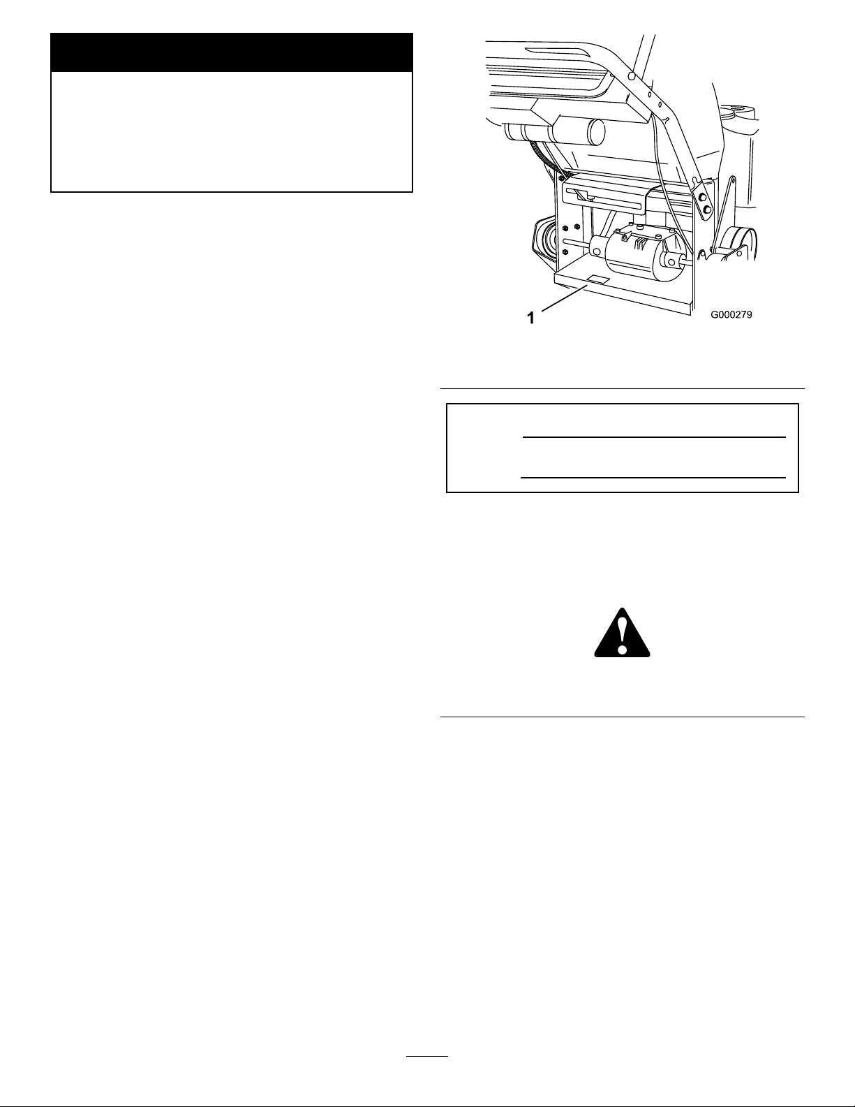
Figure1
1.Modelandserialnumberlocation
ModelNo.
SerialNo.
Introduction
Readthisinformationcarefullytolearnhowtooperate
andmaintainyourproductproperlyandtoavoidinjury
andproductdamage.Youareresponsibleforoperating
theproductproperlyandsafely.
YoumaycontactTorodirectlyatwww .Toro.comfor
productandaccessoryinformation,helpndinga
dealer,ortoregisteryourproduct.
Wheneveryouneedservice,genuineT oroparts,or
additionalinformation,contactanAuthorizedService
DealerorToroCustomerServiceandhavethemodel
andserialnumbersofyourproductready .Figure1
identiesthelocationofthemodelandserialnumbers
ontheproduct.Writethenumbersinthespace
provided.
Thismanualidentiespotentialhazardsandhas
safetymessagesidentiedbythesafetyalertsymbol
(Figure2),whichsignalsahazardthatmaycauseserious
injuryordeathifyoudonotfollowtherecommended
precautions.
Figure2
1.Safetyalertsymbol
Thismanualuses2otherwordstohighlightinformation.
Importantcallsattentiontospecialmechanical
informationandNoteemphasizesgeneralinformation
worthyofspecialattention.
Contents
Introduction.................................................................2
Safety...........................................................................4
SafeOperatingPractices.......................................4
ToroMowerSafety...............................................5
SlopeChart..........................................................7
SafetyandInstructionalDecals.............................8
ProductOverview......................................................10
Controls.............................................................10
©2009—TheToro®Company
8111LyndaleAvenueSouth
Bloomington,MN55420
Contactusatwww.Toro.com.
2
PrintedintheUSA.
AllRightsReserved
Page 3

Specications.....................................................11
Attachments/Accessories...................................11
Operation...................................................................12
AddingFuel.......................................................12
CheckingtheEngineOilLevel............................13
ThinkSafetyFirst...............................................13
UsingtheParkingBrake......................................13
StartingandStoppingtheEngine........................13
OperatingtheMowerPowerTakeOff
(PTO)............................................................14
TheSafetyInterlockSystem................................15
DrivingForwardorBackward.............................15
UsingtheLowerControlBar..............................15
StoppingtheMachine.........................................16
TransportingMachines.......................................16
SideDischargingorMulchingtheGrass..............17
AdjustingtheHeight-of-Cut...............................17
AdjustingtheAnti-ScalpRollers.........................17
AdjustingtheHandleHeight..............................18
AdjustingtheFlowBafe...................................19
PositioningtheFlowBafe.................................20
UsingtheMid-SizeWeight..................................21
Maintenance...............................................................22
RecommendedMaintenanceSchedule(s)................22
Lubrication.............................................................22
HowtoGrease...................................................22
LubricatingtheCasterandWheel
Bearings.........................................................23
GreasingtheTransmissionCouplers...................23
GreasingthePTODriveBeltIdlerandMower
DeckBeltIdler...............................................23
EngineMaintenance...............................................24
ServicingtheAirCleaner....................................24
ServicingtheEngineOil.....................................25
ServicingtheSparkPlugs....................................27
FuelSystemMaintenance.......................................28
DrainingtheFuelTank.......................................28
ReplacingtheFuelFilter.....................................28
ElectricalSystemMaintenance................................29
ServicingtheFuse..............................................29
DriveSystemMaintenance.....................................30
AdjustingtheControlBar...................................30
CheckingtheTirePressure.................................30
ReplacingtheCasterWheelFork
Bushings........................................................31
ServicingtheCasterWheelandBearings.............31
AdjustingtheElectricClutch..............................32
CoolingSystemMaintenance..................................33
CleaningtheAirIntakeScreen............................33
BrakeMaintenance.................................................33
ServicingtheBrakes...........................................33
BeltMaintenance....................................................34
ReplacingtheTractionDriveBelt........................34
ReplacingtheTransmissionBelt.........................34
ReplacingtheMowerBelt...................................35
ReplacingthePTODriveBelt.............................36
AdjustingthePTODriveBeltIdlerSpring
Anchor...........................................................37
MowerDeckMaintenance......................................37
ServicingtheCuttingBlades...............................37
CorrectingtheMowerQualityofCut..................39
FrameSetUp.....................................................40
CheckingtheMowerDeckFront-to-Rear
Pitch...............................................................41
ChangingtheMowerDeckFront-to-Rear
Pitch...............................................................42
CheckingtheMowerDeckSide-to-Side
Height............................................................42
ChangingtheMowerDeckSide-to-Side
Height............................................................43
MatchingHeightofCut......................................43
ReplacingtheGrassDeector.............................44
Storage.......................................................................45
CleaningandStorage..........................................45
Troubleshooting.........................................................46
Schematics.................................................................48
3
Page 4

Safety
Note:Theadditionofattachmentsmadeby
othermanufacturersthatdonotmeetAmerican
NationalStandardsInstitutecerticationwillcause
noncomplianceofthismachine.
Improperuseormaintenancebytheoperatororowner
canresultininjury.Toreducethepotentialforinjury,
complywiththesesafetyinstructionsandalwayspay
attentiontothesafetyalertsymbol,whichmeans
CAUTION,WARNING,orDANGER-“personalsafety
instruction."Failuretocomplywiththeinstructionmay
resultinpersonalinjuryordeath.
SafeOperatingPractices
–Useonlyanapprovedcontainer
–Neverremovegascaporaddfuelwithengine
running.Allowenginetocoolbeforerefueling.
Donotsmoke.
–Neverrefuelordrainthemachineindoors.
•Checkthatoperator’spresencecontrols,safety
switchesandshieldsareattachedandfunctioning
properly.Donotoperateunlesstheyarefunctioning
properly.
Operation
•Neverrunanengineinanenclosedarea.
•Onlyoperateingoodlight,keepingawayfromholes
andhiddenhazards.
ThefollowinginstructionsarefromANSIstandard
B71.4-2004.
Training
•ReadtheOperator’sManualandothertraining
material.Iftheoperator(s)ormechanic(s)cannot
readEnglishitistheowner’sresponsibilitytoexplain
thismaterialtothem.
•Becomefamiliarwiththesafeoperationofthe
equipment,operatorcontrols,andsafetysigns.
•Alloperatorsandmechanicsshouldbetrained.The
ownerisresponsiblefortrainingtheusers.
•Neverletchildrenoruntrainedpeopleoperateor
servicetheequipment.Localregulationsmayrestrict
theageoftheoperator.
•Theowner/usercanpreventandisresponsiblefor
accidentsorinjuriesoccurringtohimselforherself,
otherpeopleorproperty.
•Besurealldrivesareinneutralandparkingbrakeis
engagedbeforestartingengine.Onlystartengine
fromtheoperator’sposition.
•Besureofyourfootingwhileusingthismachine,
especiallywhenbackingup.Walk,don’trun.Never
operateonwetgrass.Reducedfootingcouldcause
slipping.
•Slowdownanduseextracareonhillsides.Besure
totravelsidetosideonhillsides.Turfconditions
canaffectthemachine’sstability.Usecautionwhile
operatingneardrop-offs.
•Slowdownandusecautionwhenmakingturnsand
whenchangingdirectionsonslopes.
•Neverraisedeckwiththebladesrunning.
•NeveroperatewiththePTOshield,orotherguards
notsecurelyinplace.Besureallinterlocksare
attached,adjustedproperly ,andfunctioningproperly.
•Neveroperatewiththedischargedeectorraised,
removedoraltered,unlessusingagrasscatcher.
Preparation
•Evaluatetheterraintodeterminewhataccessories
andattachmentsareneededtoproperlyand
safelyperformthejob.Onlyuseaccessoriesand
attachmentsapprovedbythemanufacturer.
•Wearappropriateclothingincludinghardhat,safety
glassesandhearingprotection.Longhair,loose
clothingorjewelrymaygettangledinmovingparts.
•Inspecttheareawheretheequipmentistobeused
andremoveallobjectssuchasrocks,toysandwire
whichcanbethrownbythemachine.
•Useextracarewhenhandlinggasolineandother
fuels.Theyareammableandvaporsareexplosive.
•Donotchangetheenginegovernorsettingor
overspeedtheengine.
•Stoponlevelground,disengagedrives,engage
parkingbrake,shutoffenginebeforeleavingthe
operator’spositionforanyreasonincludingemptying
thecatchersoruncloggingthechute.
•Stopequipmentandinspectbladesafterstriking
objectsorifanabnormalvibrationoccurs.Make
necessaryrepairsbeforeresumingoperations.
•Keephandsandfeetawayfromthecuttingunit.
•Lookbehindanddownbeforebackinguptobesure
ofaclearpath.
4
Page 5

•Keeppetsandbystandersaway .
•Slowdownandusecautionwhenmakingturnsand
crossingroadsandsidewalks.Stopbladesifnot
mowing.
•Beawareofthemowerdischargedirectionanddo
notpointitatanyone.
•Donotoperatethemowerundertheinuenceof
alcoholordrugs.
•Usecarewhenloadingorunloadingthemachine
intoorfromatrailerortruck.
•Usecarewhenapproachingblindcorners,shrubs,
trees,orotherobjectsthatmayobscurevision.
Maintenanceandstorage
•Disengagedrives,setparkingbrake,stopengineand
removekeyordisconnectsparkplugwire.Waitfor
allmovementtostopbeforeadjusting,cleaningor
repairing.
•Cleangrassanddebrisfromcuttingunit,drives,
mufers,andenginetohelppreventres.Cleanup
oilorfuelspillage.
•Letenginecoolbeforestoringanddonotstorenear
ame.
•Shutofffuelwhilestoringortransporting.Donot
storefuelnearamesordrainindoors.
•Parkmachineonlevelground.Setparkingbrake.
Neverallowuntrainedpersonneltoservicemachine.
•Usejackstandstosupportcomponentswhen
required.
•Carefullyreleasepressurefromcomponentswith
storedenergy.
•Disconnectthebatteryorremovesparkplugwire
beforemakinganyrepairs.Disconnectthenegative
terminalrstandthepositivelast.Reconnectthe
positiverstandnegativelast.
•Usecarewhencheckingblades.Wraptheblade(s)or
weargloves,andusecautionwhenservicingthem.
Onlyreplaceblades.Neverstraightenorweldthem.
•Keephandsandfeetawayfrommovingparts.If
possible,donotmakeadjustmentswiththeengine
running.
•Keepallpartsingoodworkingconditionandall
hardwaretightened.Replaceallwornordamaged
decals.
ToroMowerSafety
Thefollowinglistcontainssafetyinformationspecic
toToroproductsandothersafetyinformationyoumust
know .
Thisproductiscapableofamputatinghandsand
feetandthrowingobjects.Alwaysfollowallsafety
instructionstoavoidseriousinjuryordeath.
Thisproductisdesignedforcuttingandrecyclinggrass
or,whenequippedwithagrassbagger,forcatching
cutgrass.Anyuseforpurposesotherthanthesecould
provedangeroustouserandbystanders.
GeneralOperation
•Besuretheareaisclearofotherpeoplebefore
mowing.Stopthemachineifanyoneentersthearea.
•Donottouchequipmentorattachmentpartswhich
maybehotfromoperation.Allowtocoolbefore
attemptingtomaintain,adjustorservice.
•UseonlyToroapprovedattachments.Warrantymay
bevoidedifusedwithunapprovedattachments.
•Checkcarefullyforoverheadclearances(i.e.
branches,doorways,electricalwires)before
operatingunderanyobjectsanddonotcontact
them.
SlopeOperation
Allslopesandrampsrequireextracaution.Ifyoufeel
uneasyonaslope,donotmowit.
•Removeobstaclessuchasrocks,treelimbs,etc.from
themowingarea.
•Watchforholes,rutsorbumps.Tallgrasscanhide
obstacles.
•Usecautionneardrop-offs,ditches,orembankments.
Themachinecouldsuddenlyturnoverifawheel
goesovertheedgeofaclifforditch,orifanedge
cavesin.
•Useextracarewithgrasscatchersorother
attachments.Thesecanchangethestabilityofthe
machine.
•Keepallmovementonslopesslowandgradual.Do
notmakesuddenchangesinspeedordirection.
•Mowslopessidetoside.
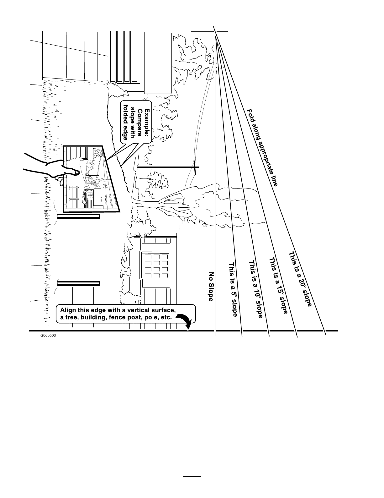
•Donotmowslopesgreaterthan20degrees.
Service
•Neverstorethemachineorfuelcontainerinside
wherethereisanopename,suchasnearawater
heaterorfurnace.
•Keepnutsandboltstight,especiallytheblade
attachmentbolts.Keepequipmentingood
condition.
•Nevertamperwithsafetydevices.Checksafety
systemsforproperoperationbeforeeachuse.
5
Page 6

•Useonlygenuinereplacementpartstoensurethat
originalstandardsaremaintained.
•Checkbrakeoperationfrequently.Adjustandservice
asrequired.
6
Page 7
SlopeChart7SafetyandInstructionalDecals
Page 8

Safetydecalsandinstructionsareeasilyvisibletotheoperatorandarelocatednearanyareaof
82- 2280
REV ERSE TRAC T I ON DRI V E
potentialdanger.Replaceanydecalthatisdamagedorlost.
82-2280
82-2290
43-8480
95-2814
52-2010
66-1340
1.Warning—wearhearingprotection.
68-8340
98-0776
98-3256
98-4387
98-5954
8
Page 9
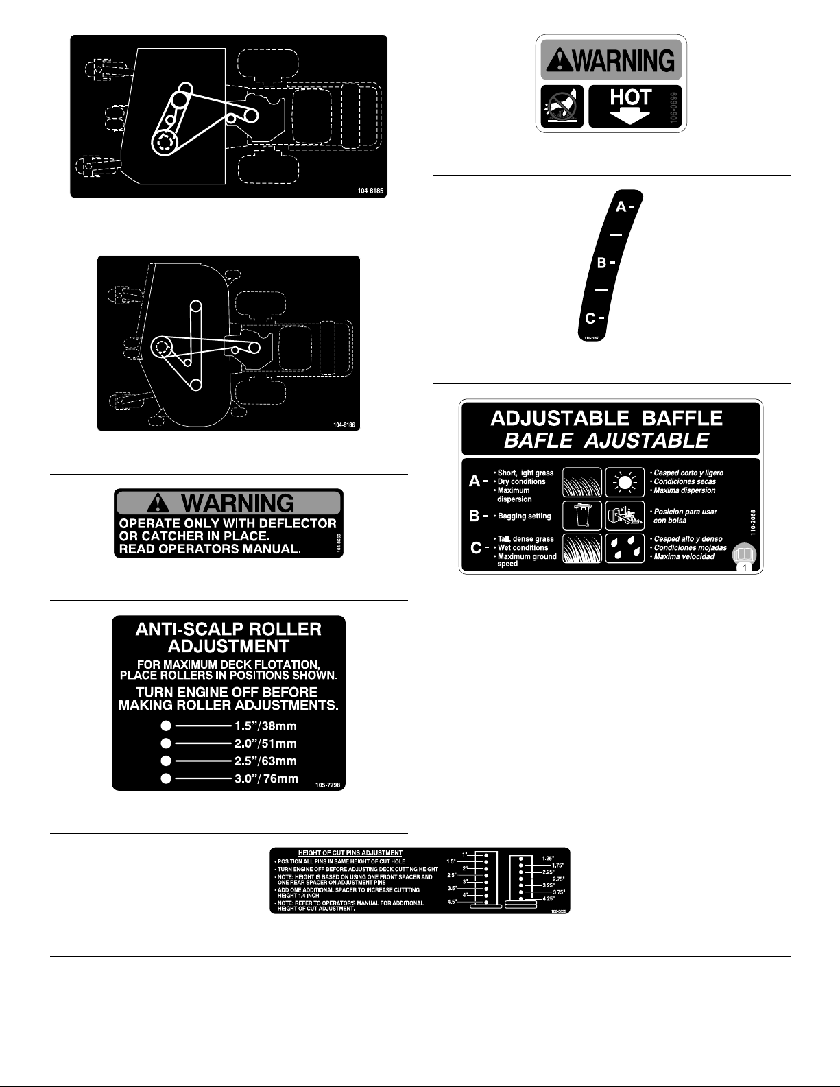
106-0699
104-8185
110-2067
104-8186
104-8569
110-2068
1.ReadtheOperator’sManual.
105-7798
106-0635
9
Page 10
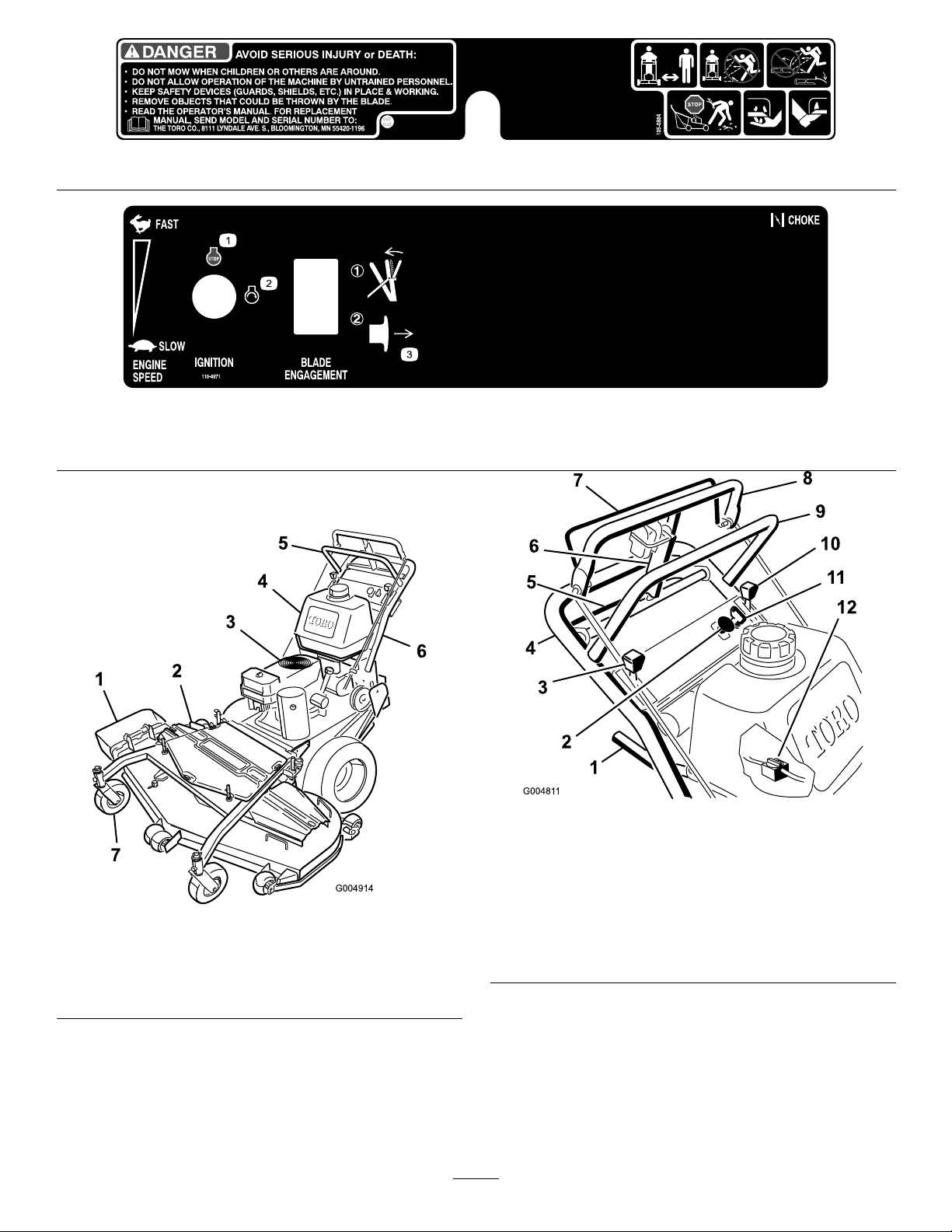
105-0884
110-4971
1.Engine—stop
2.Engine—Start3.EngagebalethenpulloutonthePTO
toengagetheblade.
ProductOverview
Figure3
1.Sidedischargechute5.Controls
2.Mowerdeck6.Handle
3.Recoilstarter
4.Gastank
7.Casterwheel
Controls
Becomefamiliarwithallthecontrols(Figure4)before
youstarttheengineandoperatethemachine.
Figure4
1.Gearshiftlever
2.Powertakeoffswitch
(PTO)
3.Chokecontrol
4.Lowerhandle10.Throttlecontrol
5.Lowercontrolbar11.Ignitionswitch
6.Parkingbrake
lever-releasedposition
7.Bladecontrolbail
8.Uppercontrolbar
9.Upperhandle
12.Fuelshut-offvalve
ThrottleControl
Thethrottlecontrolhastwopositions:FastandSlow.
Choke
Usethechoketostartacoldengine.
10
Page 11

BladeControlBail
Specications
Thebailisusedinconjunctionwiththepowertakeoff
switch(PTO)toengagetheclutchtodrivethemower
blades.Releasethemowercontrolbailtodisengagethe
mowerblades.
PowerTakeOffSwitch(PTO)
Thispullswitchisusedinconjunctionwiththeblade
controlbailtoengagetheclutchtodrivethemower
blades.
GearShiftLever
Thetransmissionhasveforwardspeeds,neutraland
reverse,andhasanin-lineshiftpattern.
Important:Donotshiftwhileunitismoving,as
transmissiondamagemayoccur.
UpperControlBar
Shifttothedesiredgearandpushforwardontheupper
controlbartoengageforwardtractionoperationand
pullbacktobrakeforwardmovement.Pullbackon
rightsideofuppercontrolbartoturnrightandleftside
toturnleft.
LowerControlBar
Note:Specicationsanddesignaresubjecttochange
withoutnotice.
36inchmowers:
Widthwithdeectordown51–1/8inches(130cm)
Length
Heightwithhandleinlowest
position
Weight
40inchmowers:
Widthwithdeectordown55–1/2inches(141cm)
Length
Heightwithhandleinlowest
position
Weight
48inchmowers:
Widthwithdeectordown63–1/2inches(161cm)
Length
Heightwithhandleinlowest
position
Weight
82–3/4inches(210cm)
41–3/16inches(105cm)
588lb(267kg)
79–1/2inches(202cm)
41–3/16inches(105cm)
596lb(270kg)
82inches(208cm)
41–3/16inches(105cm)
649lb(294kg)
Shifttransmissiontoreverseandsqueezethelower
controlbarandhandletogethertoengagerearward
tractionassistoperation.
ParkingBrakeLever
Pullbackonuppercontrolbarandswingbrakeleverup
againsttheupperhandle(Figure4).
IgnitionSwitch
Thisswitchisusedinconjunctionwithrecoilstarterand
hastwopositions:RunandOff.
RecoilStarter
Pullrecoilstarterhandletostartengine(notshownin
Figure4).
FuelShut-offValve
Closethefuelshut-offvalvewhentransportingor
storingmower.
52inchmowers:
Widthwithdeectordown67–5/8inches(171.7cm)
Length
Heightwithhandleinlowest
position
Weight
82inches(208cm)
41–3/16inches(105cm)
684lb(310kg)
Attachments/Accessories
AselectionofToroapprovedattachmentsand
accessoriesareavailableforusewiththemachineto
enhanceandexpanditscapabilities.Contactyour
AuthorizedServiceDealerorDistributororgoto
www.T oro.comforalistofallapprovedattachments
andaccessories.
11
Page 12

Operation
Note:Determinetheleftandrightsidesofthe
machinefromthenormaloperatingposition.
AddingFuel
Useunleadedregulargasolinesuitableforautomotive
use(85pumpoctaneminimum).Leadedregular
gasolinemaybeusedifunleadedregularisnotavailable.
Important:Neverusemethanol,gasoline
containingmethanol,orgasoholcontainingmore
than10%ethanolbecausethefuelsystemcouldbe
damaged.Donotmixoilwithgasoline.
Incertainconditions,gasolineisextremely
ammableandhighlyexplosive.Areor
explosionfromgasolinecanburnyouand
othersandcandamageproperty.
•Fillthefueltankoutdoors,inanopenarea,
whentheengineiscold.Wipeupany
gasolinethatspills.
•Neverllthefueltankinsideanenclosed
trailer.
•Donotllthefueltankcompletelyfull.Add
gasolinetothefueltankuntilthelevelis1/4
to1/2inch(6to13mm)belowthebottomof
thellerneck.Thisemptyspaceinthetank
allowsgasolinetoexpand.
•Neversmokewhenhandlinggasoline,and
stayawayfromanopenameorwhere
gasolinefumesmaybeignitedbyaspark.
•Storegasolineinanapprovedcontainerand
keepitoutofthereachofchildren.Never
buymorethana30-daysupplyofgasoline.
Incertainconditionsduringfueling,static
electricitycanbereleasedcausingaspark
whichcanignitethegasolinevapors.Are
orexplosionfromgasolinecanburnyouand
othersandcandamageproperty.
•Alwaysplacegasolinecontainersonthe
groundawayfromyourvehiclebeforelling.
•Donotllgasolinecontainersinsidea
vehicleoronatruckortrailerbedbecause
interiorcarpetsorplastictruckbedliners
mayinsulatethecontainerandslowtheloss
ofanystaticcharge.
•Whenpractical,removegas-powered
equipmentfromthetruckortrailerand
refueltheequipmentwithitswheelsonthe
ground.
•Ifthisisnotpossible,thenrefuelsuch
equipmentonatruckortrailerfroma
portablecontainer,ratherthanfroma
gasolinedispensernozzle.
•Ifagasolinedispensernozzlemustbeused,
keepthenozzleincontactwiththerimof
thefueltankorcontaineropeningatall
timesuntilfuelingiscomplete.
Gasolineisharmfulorfatalifswallowed.
Long-termexposuretovaporscancauseserious
injuryandillness.
•Avoidprolongedbreathingofvapors.
•Keepfaceawayfromnozzleandgastankor
conditioneropening.
•Keepgasawayfromeyesandskin.
•Donotoperatewithoutentireexhaust
systeminplaceandinproperworking
condition.
UsingStabilizer/Conditioner
Useafuelstabilizer/conditionerinthemachineto
providethefollowingbenets:
•Keepsgasolinefreshduringstorageof90daysor
less.Forlongerstorageitisrecommendedthatthe
fueltankbedrained.
•Cleanstheenginewhileitruns
•Eliminatesgum-likevarnishbuildupinthefuel
system,whichcauseshardstarting
12
Page 13

Important:Donotusefueladditivescontaining
methanolorethanol.
Addthecorrectamountofgasstabilizer/conditioner
tothegas.
Note:Afuelstabilizer/conditionerismosteffective
whenmixedwithfreshgasoline.Tominimizethe
chanceofvarnishdepositsinthefuelsystem,usefuel
stabilizeratalltimes.
Figure5
1.Warning—wearhearingprotection.
UsingtheParkingBrake
FillingtheFuelTank
1.Shuttheengineoffandsettheparkingbrake.
2.Cleanaroundeachfueltankcapandremovethecap.
3.Addunleadedregulargasolinetobothfueltanks,
untilthelevelis1/4to1/2inch(6mmto13mm)
belowthebottomofthellerneck.
Thisspaceinthetankallowsgasolinetoexpand.
Donotllthefueltankscompletelyfull.
4.Installfueltankcapssecurely.
5.Wipeupanygasolinethatmayhavespilled.
CheckingtheEngineOilLevel
Beforeyoustarttheengineandusethemachine,check
theoillevelintheenginecrankcase;refertoChecking
OilLevelin,page
Note:Determinetheleftandrightsidesofthe
machinefromthenormaloperatingposition.
Stoponlevelground,disengagedrives,engageparking
brake,shutoffengineandremovekey.Alwayssetthe
parkingbrakewhenyoustopthemachineorleaveit
unattended.
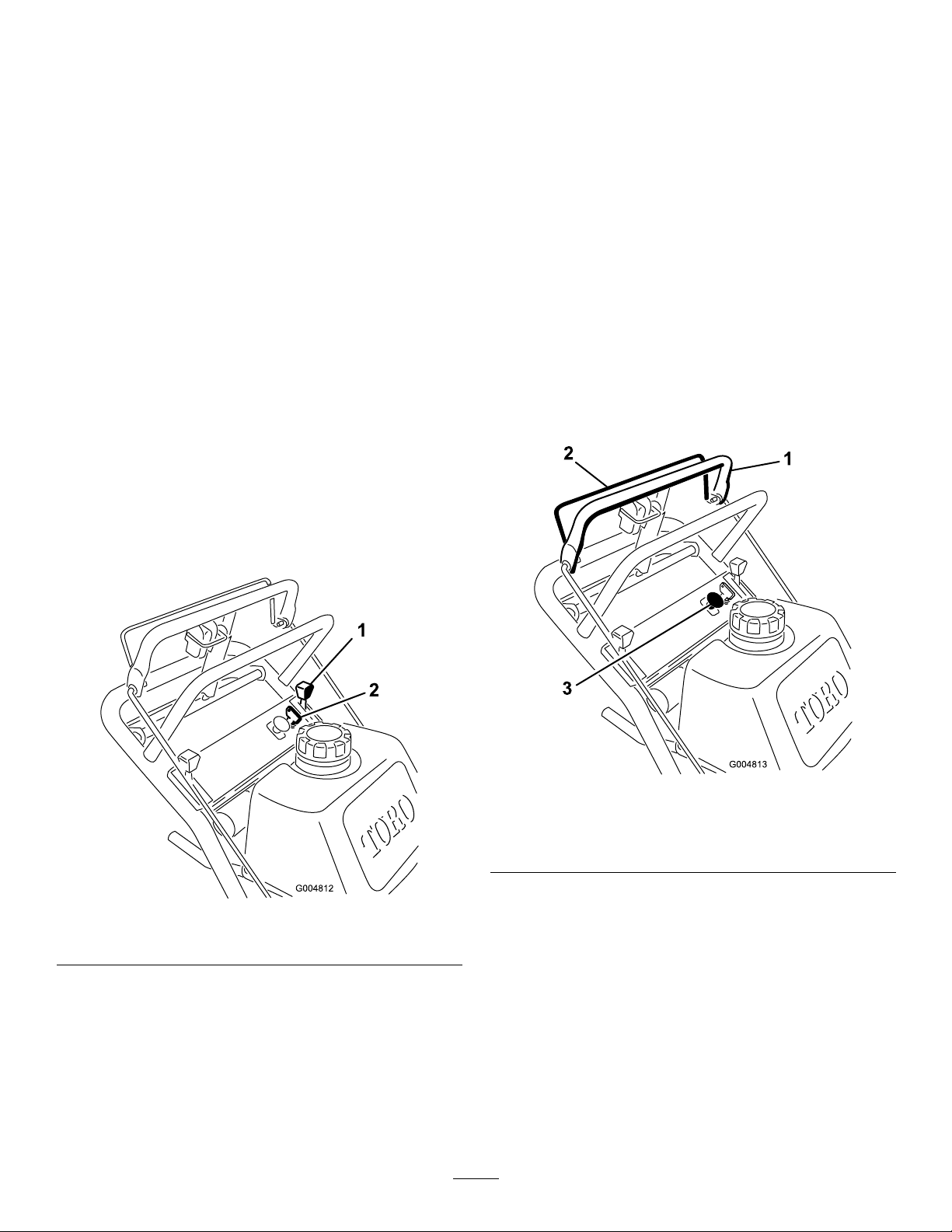
SettingtheParkingBrake
1.Pulltheuppercontrolbar(Figure6)rearwardand
holditinthisposition.
2.Lifttheparkingbrakelock(Figure6)upand
graduallyreleasetheuppercontrolbar.Thebrake
lockshouldstayintheset(locked)position.
ThinkSafetyFirst
Carefullyreadallthesafetyinstructionsanddecalsin
thesafetysection.Knowingthisinformationcould
helpyouoranybystandersavoidinjury.
Theuseofprotectiveequipmentforeyes,hearing,feet
andheadisrecommended.
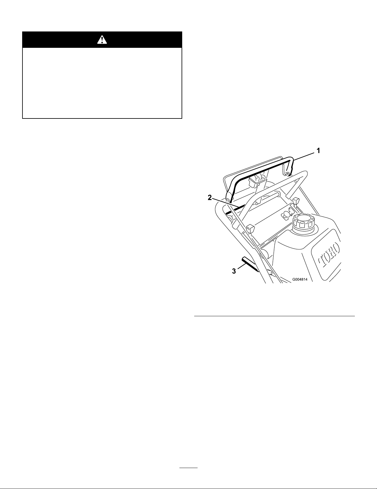
Thismachineproducessoundlevelsinexcess
of85dBAattheoperator’searandcancause
hearinglossthroughextendedperiodsof
exposure.
Wearhearingprotectionwhenoperatingthis
machine.
Figure6
1.Uppercontrolbar3.Fixedbar
2.Parkingbrakelever-set
position
ReleasingtheParkingBrake
1.Pullrearwardontheuppercontrolbar.Lowerthe
parkingbrakelocktothereleasedposition.
2.Graduallyreleasetheuppercontrolbar.
StartingandStoppingthe
Engine
StartingtheEngine
1.Makesuresparkplugwire(s)areinstalledonspark
plug(s)andfuelvalveisopen.
13
Page 14
2.Movetheshiftlevertoneutral,settheparkingbrake
andturnignitionkeytorun.
3.Movethethrottlecontroltofastandmovethe
chokelevertotheonpositionbeforestartingacold
engine.
Note:Awarmorhotengineusuallydoesnot
requireanychoking.Tostartawarmengine,move
throttlecontroltothefastposition.
OperatingtheMowerPower
TakeOff(PTO)
Thepowertakeoffswitch(PTO)inconjunctionwith
thebladecontrolbailengagesanddisengagespowerto
theelectricclutchandmowerblades.
EngagingtheMowerBlades(PTO)
4.Grasprecoilstarterhandlermlyandpullout
untilpositiveengagementresults;thenpullhandle
vigorouslytostartengineandallowropetorecoil
slowly.
Important:Donotpullrecoilropetoitslimit
orletgoofthestarterhandlewhenropeis
pulledoutbecauseropemaybreakorrecoil
assemblymaybedamaged.
StoppingtheEngine
1.Movethethrottlelevertotheslowposition
(Figure7).
2.Letengineidlefor30to60secondsbeforeturning
theignitionkeytooff.
3.Turntheignitionkeytooff(Figure7).
1.Releasetheuppercontrolbartostopthemachine
(Figure8).
2.Toengagetheblades,squeezebladecontrolbail
againsttheuppercontrolbar(Figure8).
3.Pullthepowertakeoffswitch(PTO)upand
release.Holdthebladecontrolbailagainstthe
uppercontrolbarwhileoperating.
4.Repeattheproceduretoengagethemowerbladesif
thebladecontrolbailisreleased.
Figure7
1.Throttlelever2.Ignitionkey
4.Settheparkingbrakeandremovekey.
5.Pullthewireoffsparkplug(s)topreventpossibility
ofaccidentalstartingbeforestoringmachine.
6.Closethefuelshutoffvalvebeforestoringmachine.
Important:Makesurethefuelshutoffvalveis
closedbeforetransportingorstoringmachine,
asfuelleakagemayoccur.
Figure8
1.Uppercontrolbar
2.Bladecontrolbail
3.Powertakeoffswitch
(PTO)
DisengagingtheMowerBlades(PTO)
Releasethebladecontrolbailtodisengagetheblades
(Figure8).
14
Page 15
TheSafetyInterlockSystem
Ifthesafetyinterlockswitchesaredisconnected
ordamagedthemachinecouldoperate
unexpectedlycausingpersonalinjury.
•Donottamperwiththeinterlockswitches.
throttlecontrolinthefastpositionforbestmowing
performance.
DrivingForward
1.Togoforward,movetheshiftlevertoaforward
gear(Figure9).
2.Releasetheparkingbrake;refertoReleasingthe
ParkingBrakeinOperation.
•Checktheoperationoftheinterlock
switchesdailyandreplaceanydamaged
switchesbeforeoperatingthemachine.
UnderstandingtheSafetyInterlock
System
Thesafetyinterlocksystemisdesignedtopreventthe
mowerbladesfromrotatingunless:
•Thecontrolbailispressedagainsttheuppercontrol
bar.
•Thepowertakeoffswitch(PTO)ispulledon.
Thesafetyinterlocksystemisdesignedtostopthe
mowerbladesifyoureleasethebladecontrolbail.
TestingtheSafetyInterlockSystem
ServiceInterval:Beforeeachuseordaily
Testthesafetyinterlocksystembeforeyouusethe
machineeachtime.
3.Slowlypressontheuppercontrolbartomove
forward(Figure9).
Togostraight,applyequalpressuretobothendsof
theuppercontrolbar(Figure9).
Toturn,releasepressureontheuppercontrolbar
sideinthedirectionyouwanttoturn(Figure9).
Note:Ifthesafetysystemdoesnotoperateas
describedbelow ,haveanAuthorizedServiceDealer
repairthesafetysystemimmediately.
1.Settheparkingbrakeandstarttheengine;referto
StartingandStoppingtheEngine.
2.Squeezethebladecontrolbailagainstuppercontrol
bar.Thebladesshouldnotrotate.
3.Thencontinueholdingthebladecontrolbailand
pulluponthebladecontrolswitchandrelease.The
clutchshouldengageandthemowerbladesbegin
rotating.
4.Releasethebladecontrolbail.Thebladesshould
stoprotating.
5.Withtheenginerunning,pullupthepowertakeoff
switch(PTO)andreleasewithoutholdingtheblade
controlbail.Thebladesshouldnotrotate.
DrivingForwardorBackward
Thethrottlecontrolregulatestheenginespeedas
measuredinRPM(revolutionsperminute).Placethe
Figure9
1.Uppercontrolbar
2.Lowercontrolbar
3.Shiftlever
DrivingBackward
1.Togobackward,movetheshiftlevertoreversegear.
2.Releasetheparkingbrake;refertoReleasingthe
ParkingBrake.
3.Slowlysqueezethelowercontrolbarandlower
handletogethertomoverearward(Figure9).
UsingtheLowerControlBar
Thisprocedureisfordrivingupacurb.Thiscanbe
performedwhiledrivingforwardorbackward.
Note:Somecurbsdonotallowthereardrivetiresto
contactthecurb.Ifthishappens,drivethemachineup
thecurbatanangle.
15
Page 16
Abladecanbebentordamagedwhendriving
upacurb.Piecesofbladethatmaybethrown
couldseriouslyinjureorkillyouorbystanders.
Donotrunbladeswhiledrivingupacurb
forwardorbackward.
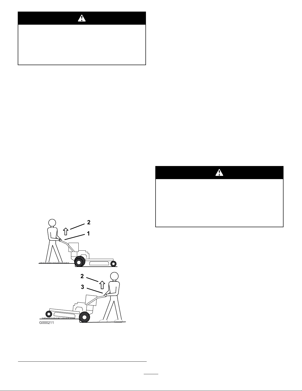
DrivingForwardUpaCurb
DrivingBackwardUpaCurb
1.Disengagethemowerblades.
2.Selectreversetodrivemachine.
3.Drivethemachineuntildrivewheelscontactcurb
(Figure10).
Note:Bothdrivewheelsshouldcontactthecurb
andcasterwheelsstraight.
4.Atthesametimeengagelowercontrolbarandlift
uponthelowerhandle(Figure9andFigure10).
1.Disengagethemowerblades.
2.Selectrstgeartodrivethemachine.
3.Drivemachineuntilthecastorwheelscontactthe
curb(Figure10).
4.Liftthefrontofthemachinebypushingdownon
thelowerhandle(Figure10).
5.Drivethemachineuntildrivewheelscontactthe
curb(Figure10).
6.Lowerthefrontofthemachine(Figure10).
Note:Bothdrivewheelsshouldcontactthecurb
andcasterwheelsstraight.
7.Atthesametime,engagethelowercontrolbarand
liftuponthelowerhandletodriveoverthecurb
(Figure9andFigure10).
Note:Liftinguponthelowerhandlewillassist
drivingthemachineupacurbandnotspinthe
drivewheels.
Note:Liftinguponthelowerhandlewillassist
drivingthemachineupacurbandnotspinthe
drivewheels.
StoppingtheMachine
Tostopthemachine,pullbackontheuppercontrol
bar,releasethebladecontrolbail,andturntheignition
keytooff.Alsosettheparkingbrakeifyouleavethe
machineunattended;refertoSettingtheParkingBrake
in,page.Remembertoremovethekeyfromthe
ignitionswitch.
Childrenorbystandersmaybeinjuredifthey
moveorattempttooperatethemachinewhile
itisunattended.
Alwaysremovetheignitionkeyandsetthe
parkingbrakewhenleavingthemachine
unattended,evenifjustforafewminutes.
1.LowerControlBar
engagedandmower
inreverse.
2.Pulluptoassistmachine
Figure10
3.LowerControlBar
engagedandmower
goingforward.
TransportingMachines
Useaheavy-dutytrailerortrucktotransportthe
machine.Ensurethatthetrailerortruckhasall
necessarybrakes,lighting,andmarkingasrequiredby
law .Pleasecarefullyreadallthesafetyinstructions.
Knowingthisinformationcouldhelpyou,yourfamily,
petsorbystandersavoidinjury.
Totransportthemachine:
1.Ifusingatrailer,connectittothetowingvehicle
andconnectthesafetychains.
2.Ifapplicable,connectthetrailerbrakes.
3.Loadthemachineontothetrailerortruck.
4.Stoptheengine,removethekey ,setthebrake,and
closethefuelvalve.
5.Usethemetaltiedownloopsonthemachineto
securelyfastenthemachinetothetrailerortruck
withstraps,chains,cable,orropes(Figure11).
16
Page 17

Figure11
1.Tractionunittiedownloop
SideDischargingorMulching
theGrass
Thismowerhasahingedgrassdeectorthatdisperses
clippingstothesideanddowntowardtheturf.
Note:Allheight-of-cutpinscanusetwospacers
maximum.
1.Selectholeinheight-of-cutpostandnumberof
spacerscorrespondingtotheheight-of-cutdesired
(Figure12).
2.Usingthelifthandle,raisesideofdeckandremove
hairpincotter(Figure12).
3.Addorremovespacersifneededandthenalignthe
holesandinsertthehairpincotter(Figure12).
Note:Spareheight-of-cutspacersmaybestored
onpostsandretainedbyahairpincotter.
Important:Allfourhairpincotterpinsmustbe
inthesameholelocationandwiththecorrect
numberofspacersforalevelcut.
Withoutthegrassdeector,dischargecover,
orcompletegrasscatcherassemblymounted
inplace,youandothersareexposedtoblade
contactandthrowndebris.Contactwith
rotatingmowerblade(s)andthrowndebriswill
causeinjuryordeath.
•Neverremovethegrassdeectorfrom
themowerbecausethegrassdeector
routesmaterialdowntowardtheturf.Ifthe
grassdeectoriseverdamaged,replaceit
immediately.
•Neverputyourhandsorfeetunderthe
mower.
•Nevertrytocleardischargeareaormower
bladesunlessyoureleasethebailandthe
powertakeoff(PTO)isoff.Rotatethe
ignitionkeytoOff.Alsoremovethekeyand
pullthewire(s)offthesparkplug(s).
AdjustingtheHeight-of-Cut
Theheight-of-cutcanbeadjustedfrom1to4-1/2
inches(25to114mm)in1/4inch(6mm)increments.
Adjustmentisdonebyrelocatingfourhairpincotter
pinsindifferentholelocationsandbyaddingor
removingspacers.
Figure12
1.CarrierFrame4.Spacers
2.HairpinCotter5.Frontheight-of-cutpost
3.Backheight-of-cutpost
AdjustingtheAnti-Scalp
Rollers
Theanti-scalprollersneedtobeadjustedintheproper
holelocationforeachheight-of-cutposition.There
needstobe3/8inch(10mm)minimumclearance
abovetheground.
Note:Allheight-of-cutpinsneedatleastonespacer
ordamagecanoccurtothebushingifnoneareused.
Note:Iftheanit-scalprollersareadjustedtoolow,it
cancauseexcesswearoftherollers.
17
Page 18

1.Afteradjustingtheheight-of-cut,checkthe
anti-scalprollerssothatthereisaminimumof
3/8inch(10mm)clearanceabovetheground
(Figure13,Figure14,Figure15).
2.Ifadjustmentisneeded,removethebolt,washers
andnut(Figure13,Figure14,Figure15).
3.Selectaholepositionsotheanti-scalprollersare
aminimumof3/8inch(10mm)offtheground
(Figure13,Figure14,Figure15).
4.Installtheboltandnut(Figure13,Figure14,
Figure15).
Figure14
40inch,48inch,and52inchMowerDecks
1.Mowerdeck4.Bushing
2.Bolt5.Anti-scalprollers
3.Spacer
6.Nut
Figure13
40inch,48inch,and52inchMowerDecks
1.Mowerdeck4.Anti-scalprollers
2.Bolt5.Nut
3.Spacer
Figure15
36inchMowerDeck
1.Mowerdeck4.Anti-scalprollers
2.Bolt5.Nut
3.Spacer
5.Incertainmowingconditionsandterrain,a
mismatchofcuttingheightmaybeseen.Adjusting
theoutsideanti-scalprollerstotheminimumsetting
of3/8inch(10mm)willhelppreventthemower
deckcuttingtoolowontheoutsideandminimize
themismatch.
AdjustingtheHandleHeight
Thehandlepositioncanbeadjustedtomatchthe
operator’sheightpreference.
18
Page 19

1.Removethehairpincotter,washerandclevispin
securingcontrolrodttingtotheidlerbracket
(Figure16).
Figure16
1.Controlrodandtting
2.Idlerbracket5.Hairpincotter
3.Clevispin6.Rodtting
4.Washer
5.Checkthecontrolbarforcorrectadjustment.Refer
toAdjustingtheControlBarinthemaintenance
section.
6.Checktheparkingbrakeadjustment.Referto
CheckingtheBrakesinthemaintenancesection.
AdjustingtheFlowBafe
Themowerdischargeowcanbeadjustedfordifferent
typesofmowingconditions.Positionthecamlockand
bafetogivethebestqualityofcut.
1.DisengagethePTO,movethemotioncontrol
leverstotheneutrallockedpositionandsetthe
parkingbrake.
2.Stoptheengine,removethekey,andwaitforall
movingpartstostopbeforeleavingtheoperating
position.
3.Toadjustthecamlock,swingtheleveruptoloosen
thecamlock(Figure18).
2.Loosentheupperangebolts(3/8x1inch)and
theangenutsecuringthehandletotherearframe
(Figure17).
Figure17
1.Upperhandle5.Uppermountinghole
2.Rearframe
3.Flangenut,(3/8inch)
4.Flangebolt,(3/8x1inch)
6.Lowermountingholes
7.Lowposition
8.Highposition
3.Removethelowerangebolts(3/8x1inch)and
angenutssecuringthehandletotherearframe
(Figure17).
4.Adjustthebafeandcamlockintheslottothe
desireddischargeow.
5.Swingtheleverbackovertotightenthebafeand
camlock(Figure18).
6.Ifthecamdoesnotlockthebafeintoplaceoritis
tootight,loosentheleverandthenrotatethecam
lock.Adjustthecamlockuntilthedesiredlocking
pressureisachieved.
Figure18
1.Camlock4.Slot
2.Lever5.Rotatethelevertorelease
orlockthecam
3.Rotatecamtoincreaseor
decreaselockingpressure
4.Pivotthehandletothedesiredoperatingposition
andinstallthelowerangebolts(3/8x1inch)and
theangenutsintothemountingholes.Tighten
allangebolts.
19
Page 20

PositioningtheFlowBafe
Thefollowingguresareonlyrecommendationsfor
use.Adjustmentswillvarybygrasstype,moisture
content,andheightofgrass.
Note:Iftheenginepowerdrawsdownandthemower
groundspeedisthesame,openupthebafe.
PositionA
Thisisthefullrearposition(seeFigure19).The
suggesteduseforthispositionisafollows.
•Useforshort,lightgrassmowingconditions.
•Useindryconditions.
•Forsmallergrassclippings.
•Propelsgrassclippingsfartherawayfromthe
mower.
Figure20
PositionC
Figure19
PositionB
Usethispositionwhenbagging(Figure20).
Thisisthefullopenposition.Thesuggestedusefor
thispositionisasfollows(Figure21).
•Useintall,densegrassmowingconditions.
•Useinwetconditions.
•Lowerstheenginepowerconsumption.
•Allowsincreasedgroundspeedinheavyconditions.
•ThispositionissimilartothebenetsoftheToro
SFSmower.
Figure21
20
Page 21

UsingtheMid-SizeWeight
Weightsareinstalledoncertainmowerstoimprove
balanceandimproveperformance.Theweightscanbe
movedorremovedtocreateoptimizedperformance
underdifferentmowingconditionsandforoperator
preference(Figure22orFigure23).
Thefollowingtableindicatesthepositionoftheweight
asinstalledatthefactory.
MowerDeckSizeNumberofweights
36inches
40inches1Front
48inches2Rear
52inches3Rear
install
nonenone
Positionofthe
•Anyrearweightmustberemovedwhena
Tru-Track
•WhenaTru-Track
®
Sulkyisinstalled.
®
Sulkyisinstalledfrontweights
areneeded.ContactanAuthorizedServiceDealer
forthecorrectquantityofweightsandplacement.
Thefrontendofthemachinecanrapidlyrise
upwhenthemowerisremoved.Thiscould
causeseriousinjurytoyouorbystanders.
Supporttherearofthemachinewhenremoving
themowerformthecarrierframe.
weight
Figure22
Installingthefrontweight.
1.Bolt3.Weight
2.Washer4.Nut
Figure23
Installingtherearweight.
1.Nut3.Washer
2.Weight4.Bolt
21
Page 22

Maintenance
Note:Determinetheleftandrightsidesofthemachinefromthenormaloperatingposition.
RecommendedMaintenanceSchedule(s)
MaintenanceService
Interval
Aftertherst8hours
Beforeeachuseordaily
Every25hours
Every50hours
Every100hours
Every200hours
MaintenanceProcedure
•Changetheengineoil.
•Checkthesafetyinterlocksystem.
•Greasethecasterwheelsandcasterpivot.
•Checktheengineoillevel.
•Cleantheairintakescreen.
•Checkthebrakesonbothalevelsurfaceandslope.
•Inspecttheblades.
•Cleanfoamaircleanerelement.
•GreasethePTObeltidler.
•Greasethemowerdeckbeltidler.
•Checkthepaperaircleanerelement.
•Checkthetirepressure
•Checkthetractiondrivebelt
•Checkthetransmissionbelt.
•Checkthemowerbelt.
•CheckthePTOdrivebelt.
•Changetheengineoil.
•Checkthesparkplugs.
•Adjusttheelectricclutch.
•Replacethepaperaircleanerelement.
•Changetheoillter.
•Replacethefuellter.
Every250hours
Every400hours
Beforestorage
•Greasethetransmissioncouplers(moreoftenindirtyordustyconditions).
•Greasethefrontwheelbearings(moreoftenindirtyordustyconditions).
•Paintchippedsurfaces.
•Performallmaintenanceprocedureslistedabovebeforestorage.
Important:Refertoyourengineoperator’smanualforadditionalmaintenanceprocedures.
Ifyouleavethekeyintheignitionswitch,someonecouldaccidentlystarttheengineandseriously
injureyouorotherbystanders.
Removethekeyfromtheignitionanddisconnectthesparkplugwiresfromthesparkplugsbeforeyou
doanymaintenance.Setthewiresasidesothattheydonotaccidentallycontactthesparkplugs.
Lubrication
GreasewithNo.2generalpurposelithiumbaseor
molybdenumbasegrease.
HowtoGrease
1.DisengagethePTOandsettheparkingbrake.
2.Stoptheengine,removethekey,andwaitforall
movingpartstostopbeforeleavingtheoperating
position.
22
Page 23

3.Cleanthegreasettingswitharag.Makesureto
scrapeanypaintoffthefrontofthetting(s).
4.Connectagreaseguntothetting.Pumpgrease
intothettingsuntilgreasebeginstooozeoutof
thebearings.
5.Wipeupanyexcessgrease.
LubricatingtheCasterand
WheelBearings
ServiceInterval:Beforeeachuseordaily
Every400hours
1.Lubricatethefrontcasterwheelbearingsandfront
pivots(Figure24).
2.Raisetherearofthemachineandusejackstands
tosupportthemachine.
Figure25
3.Removetherearwheelandtireassemblies.
4.Removetherearwheelgreasecap.Lubricatetherear
wheelbearing(Figure24).
5.Installthegreasecap.
6.Installtherearwheelandtireassembly.
Note:Makesuretherearwheelgreasecapsare
removedbeforelubricatingrearwheels.
GreasingthePTODriveBelt
IdlerandMowerDeckBelt
Idler
ServiceInterval:Every50hours—GreasethePTO
beltidler.
Every50hours—Greasethemower
deckbeltidler.
Greasetheidlerpulleypivots(Figure26orFigure27).
Note:Youwillhavetoremovethecarriercoversto
accessthegreasettingforthemowerdeck.
Figure24
GreasingtheTransmission
Couplers
ServiceInterval:Every250hours
Lubricatethetransmissioncouplerslocatedintheback
ofthemachine(Figure25).
Figure26
40inch,48inch,and52inchMowerDeckshown
23
Page 24

Figure27
36inchMowerDeckshown
EngineMaintenance
ServicingtheAirCleaner
ServiceInterval/Specication
ServiceInterval:Every25hours—Cleanfoamair
cleanerelement.
Every50hours—Checkthepaperair
cleanerelement.
Every200hours—Replacethepaper
aircleanerelement.
Note:Servicetheaircleanermorefrequently(every
fewoperatinghours)iftheoperatingconditionsare
extremelydustyorsandy.
Important:Donotoilthefoamorpaperelement.
RemovingtheFoamandPaper
Elements
1.DisengagethePTOandsettheparkingbrake.
2.Stoptheengine,removethekey,andwaitforall
movingpartstostopbeforeleavingtheoperating
position.
3.Cleanaroundtheaircleanertopreventdirt
fromgettingintotheengineandcausingdamage
(Figure28).
4.Unscrewthecoverknobandremovetheaircleaner
cover(Figure28).
5.Removethe2wingnutsandremovetheaircleaner
assembly(Figure28).
6.Carefullypullthefoamelementoffthepaper
element(Figure28).
24
Page 25

2.Placetheaircleanerassemblyontotheaircleaner
baseandsecureitwiththe2wingnuts(Figure28).
3.Placetheaircleanercoverintopositionandtighten
thecoverknob(Figure28).
ServicingtheEngineOil
ServiceInterval/Specication
ServiceInterval:Beforeeachuseordaily—Checkthe
engineoillevel.
Aftertherst8hours—Changethe
engineoil.
Every100hours—Changetheengine
oil.
Every200hours—Changetheoil
lter.
Note:Changetheoilmorefrequentlywhenthe
operatingconditionsareextremelydustyorsandy.
Figure28
1.Engine4.Foamelement
2.Cover
3.Wingnut
5.Paperelement
6.Coverknob
CleaningtheFoamAirCleanerElement
1.Washthefoamelementinliquidsoapandwarm
water.Whentheelementisclean,rinseitthoroughly .
2.Drytheelementbysqueezingitinacleancloth.
Important:Replacethefoamelementifitis
tornorworn.
ServicingthePaperAirCleaner
Element
1.Donotcleanthepaperlter,replaceit(Figure28).
2.Inspecttheelementfortears,anoilylm,ordamage
totherubberseal.
3.Replacethepaperelementifitisdamaged.
InstallingtheFoamandPaperElements
OilType:Detergentoil(APIserviceSF,SG,SH,orSJ)
CrankcaseCapacity:58ounces(1.7liter)withthelter
removed;51ounces(1.5liter)withoutthelterremoved
Viscosity:Refertothetable(Figure29).
Figure29
CheckingtheEngineOilLevel
1.Parkthemachineonalevelsurface.
2.DisengagethePTOandsettheparkingbrake.
Important:Topreventenginedamage,always
operatetheenginewiththecompletefoamand
paperaircleanerassemblyinstalled.
1.Carefullyslidethefoamelementontothepaperair
cleanerelement(Figure28).
3.Stoptheengine,removethekey,andwaitforall
movingpartstostopbeforeleavingtheoperating
position.
4.Cleanaroundtheoildipstick(Figure30)sothatdirt
cannotfallintothellerholeanddamagetheengine.
25
Page 26

Figure30
1.Oildipstick
2.Fillertube
5.Unscrewtheoildipstickandwipetheendclean
(Figure30).
6.Slidetheoildipstickfullyintothellertube,butdo
notthreadontotube(Figure30).
7.Pullthedipstickoutandlookattheend.Iftheoil
levelislow ,slowlypouronlyenoughoilintotheller
tubetoraisetheleveltotheFullmark.
Important:Donotoverllthecrankcasewith
oilandruntheengine;enginedamagecan
result.
Figure31
1.Oildrainvalve2.Oildrainhose
9.Slowlypourapproximately80%ofthespeciedoil
intothellertube(Figure30).
10.Checktheoillevel;refertoCheckingtheEngineOil
Level.
ChangingtheEngineOil
1.Starttheengineandletitrunveminutes.This
warmstheoilsoitdrainsbetter.
2.Parkthemachinesothatthedrainsideisslightly
lowerthantheoppositesidetoassuretheoildrains
completely.
3.DisengagethePTOandsettheparkingbrake.
4.Stoptheengine,removethekey,andwaitforall
movingpartstostopbeforeleavingtheoperating
position.
5.Slidethedrainhoseovertheoildrainvalve.
6.Placeapanbelowthedrainhose.Rotateoildrain
valvetoallowoiltodrain(Figure31).
7.Whenoilhasdrainedcompletely,closethedrain
valve.
8.Removethedrainhose(Figure31).
Note:Disposeoftheusedoilatarecyclingcenter.
11.SlowlyaddtheadditionaloiltobringittotheFull
mark.
ChangingtheOilFilter
Note:Changetheoilltermorefrequentlywhenthe
operatingconditionsareextremelydustyorsandy.
1.Draintheoilfromtheengine;refertoChangingthe
EngineOil.
2.Removetheoldlter(Figure32).
Figure32
1.Oillter
2.Adapter
3.Applyathincoatofnewoiltotherubbergasketon
thereplacementlter(Figure32).
26
Page 27

4.Installthereplacementoilltertothelteradapter,
1
turntheoillterclockwiseuntiltherubbergasket
contactsthelteradapter,thentightenthelteran
additional3/4turn(Figure32).
5.Fillthecrankcasewiththepropertypeofnewoil;
refertoServicingtheEngineOil.
6.Runtheengineforabout3minutes,stoptheengine,
andcheckforoilleaksaroundtheoillteranddrain
valve.
7.Checktheengineoillevelandaddoilifneeded.
8.Wipeupanyspilledoil.
ServicingtheSparkPlugs
ServiceInterval/Specication
ServiceInterval:Every100hours—Checkthespark
plugs.
Ensurethattheairgapbetweenthecenterandside
electrodesiscorrectbeforeinstallingthesparkplug.
Useasparkplugwrenchforremovingandinstallingthe
sparkplugsandagappingtool/feelergaugetocheckand
adjusttheairgap.Installanewsparkplugsifnecessary.
Type:Champion®RCJ8YorequivalentAirGap:
0.030inch(0.75mm)
4.Cleanaroundthesparkplugstopreventdirtfrom
fallingintotheengineandpotentiallycausing
damage.
5.Removethesparkplugsandthemetalwashers.
CheckingtheSparkPlugs
1.Lookatthecenterofthesparkplugs(Figure34).
Ifyouseelightbrownorgrayontheinsulator,the
engineisoperatingproperly.Ablackcoatingonthe
insulatorusuallymeansthattheaircleanerisdirty.
2.Ifneeded,cleanthesparkplugwithawirebrushto
removecarbondeposits.
Figure34
1.Centerelectrodeinsulator3.Airgap(nottoscale)
2.Sideelectrode
RemovingtheSparkPlugs
1.DisengagethePTOandsettheparkingbrake.
2.Stoptheengine,removethekey,andwaitforall
movingpartstostopbeforeleavingtheoperating
position.
3.Disconnectthewiresfromthesparkplugs
(Figure33).
Figure33
1.Spark-plugwire/sparkplug
Important:Alwaysreplacethesparkplugs
whenithaswornelectrodes,anoilylmonit,
orhascracksintheporcelain.
3.Checkthegapbetweenthecenterandsideelectrodes
(Figure34).Bendthesideelectrode(Figure34)if
thegapisnotcorrect.
InstallingtheSparkPlugs
1.Installthesparkplugsandthemetalwasher.Ensure
thattheairgapissetcorrectly.
2.Tightenthesparkplugsto16ft-lb(22N-m).
3.Connectthewirestothesparkplugs(Figure34).
27
Page 28

FuelSystem
Maintenance
DrainingtheFuelTank
Incertainconditions,gasolineisextremely
ammableandhighlyexplosive.Areor
explosionfromgasolinecanburnyouand
othersandcandamageproperty.
•Draingasolinefromthefueltankwhenthe
engineiscold.Dothisoutdoorsinanopen
area.Wipeupanygasolinethatspills.
Figure35
1.Fuelshut-offvalve2.Clamp
•Neversmokewhendraininggasoline,and
stayawayfromanopenameorwherea
sparkmayignitethegasolinefumes.
1.Parkthemachineonalevelsurface,toensurethe
fueltankdrainscompletely .Thendisengagethe
powertakeoff(PTO),settheparkingbrake,and
turntheignitionkeytooff.Removethekey .
2.Closethefuelshut-offvalveatthefueltank
(Figure35).
3.Squeezetheendsofthehoseclamptogether
andslideitupthefuellineawayfromfuellter
(Figure35).
4.Pullthefuellineoffthefuellter(Figure35).Open
thefuelshut-offvalveandallowthegasolinetodrain
intoagascanordrainpan.
Note:Nowisthebesttimetoinstallanewfuellter
becausethefueltankisempty.RefertoReplacing
theFuelFilter.
5.Installthefuellineontothefuellter.Slidethehose
clampclosetothevalvetosecurethefuelline.
ReplacingtheFuelFilter
ServiceInterval:Every200hours
Neverinstalladirtylterifitisremovedfromthefuel
line.
Note:Notehowthefuellterisinstalled.
Note:Wipeupanyspilledfuel.
1.DisengagethePTOandsettheparkingbrake.
2.Stoptheengine,removethekey,andwaitforall
movingpartstostopbeforeleavingtheoperating
position.
3.Closefuelshut-offvalveatfueltank(Figure35).
Note:Removethefuellinefromthefuelvalvethat
isclosesttotheengine.
4.Squeezetheendsofthehoseclampstogetherand
slidethemawayfromthelter(Figure36).
1.Hoseclamp3.Filter
2.Fuelline
28
Figure36
Page 29

5.Removethelterfromthefuellines.
6.Installanewlterandmovethehoseclampsclose
tothelter.
7.Openfuelshut-offvalveatfueltank(Figure35).
8.Checkforfuelleaksandrepairifneeded.
ElectricalSystem
Maintenance
ServicingtheFuse
Theelectricalsystemisprotectedbyafuse.Itrequires
nomaintenance.Ifthefuseblows,checkthecomponent
orcircuitformalfunctionorashort.Toreplacethefuse,
pulloutonthefuse(Figure37)toremoveorreplaceit.
1.Fuse,7.5amp,bladetype
Figure37
29
Page 30

DriveSystem
Maintenance
AdjustingtheControlBar
1.Checkthegapbetweenuppercontrolbarand
xedbarwithwheeldrivefullyengaged.Thegap
shouldbeapproximately1to1-1/4inch(25-32mm)
(Figure38).
Note:Theuppercontrolbarandxedbarmustbe
parallelwhentheuppercontrolbarisintheengaged,
drive,neutral,orbrakepositions.
Figure39
1.Controlrodandtting
2.3-1/2inch(89mm)
3.Idlerbracket
4.Clevispin
5.Washer
6.Hairpincotterpin
7.Rodtting
8.HoleF
CheckingtheTirePressure
ServiceInterval:Every50hours/Monthly(whichever
comesrst)—Checkthetirepressure
Figure38
1.Uppercontrolbar4.Handle
2.Parkingbrakelever
3.Fixedcontrolbar
5.1to1-1/4inch(25-32mm)
gap
2.Checktheoperation.Ifadjustmentisrequired,
removehairpincotter,washerandclevispinsecuring
controlrodttingtoidlerbracket(Figure39).
3.Threadtherodttingupordownontheroduntil
theproperpositionisattainedandinstalltherod
ttingtotheidlerbracketwiththeclevispin,washer
andhairpincotter.
Checkthepressureatthevalvestem(Figure40).
Maintaintheairpressureinthereartiresat12-14psi
(83-97kPa).Uneventirepressurecancauseanuneven
cut.
Note:Thefronttiresaresemi-pneumatictiresanddo
notrequireairpressuremaintenance.
Figure40
30
Page 31

ReplacingtheCasterWheel
ForkBushings
Thecasterwheelforksaremountedinbushingspressed
intothetopandbottomofthecarrierframemounting
pivottubes.Tocheckthebushings,movethecaster
forksbackandforthandside-to-side.Ifacasterforkis
loose,thebushingsarewornandmustbereplaced.
1.Raisethecuttingunitsothecasterwheelsareoff
theoor,thensupportthefrontofthemowerwith
jackstands.
2.Removethelockingpinandspacer(s)fromthetop
ofthecasterwheelfork(Figure41).
Figure42
1.MountingTube2.Bushing
5.Greasetheinsideandoutsideofthenewbushings.
Useahammerandatplatetocarefullydrivethe
bushingsintothepivottubes.
Figure41
1.LockingPin
2.Spacers4.Casterwheel
3.Pullthecasterwheelforkoutofthemountingtube,
leavingthespacer(s)onthebottomofthefork.
Rememberthelocationofthespacersoneachfork
toensurecorrectinstallation,andtomaintainalevel
deck.
4.Insertapinpunchintothemountingtubeand
carefullydriveoutthebushings(Figure42).Clean
theinsideofthemountingtube.
3.Carrierframepivottube
6.Inspectthecasterwheelforkforwearandreplace
ifnecessary(Figure41).
7.Slidethecasterwheelforkthroughthebushingsin
themountingtube.Replacethespacer(s)ontothe
forkandsecurewiththeretainingring(Figure41).
Important:Theinsidediameterofthebushings
maycollapseslightlywheninstalled.Ifthe
casterwheelforkdoesnotslideintothenew
bushings,reambothbushingstoaninside
diameterof1.126inch(29mm).
8.Greasethettingonthecarrierframepivottubes
usingNo.2generalpurposelithiumbaseor
molybdenumbasegrease.
ServicingtheCasterWheel
andBearings
Thecasterwheelsrotateonarollerbearingsupportedby
aspannerbushing.Ifthebearingiskeptwelllubricated,
wearwillbeminimal.Failuretokeepthebearingwell
lubricatedwillcauserapidwear.Awobblycasterwheel
usuallyindicatesawornbearing.
1.Removethelocknutandwheelboltholdingthe
casterwheeltothecasterfork(Figure43).
31
Page 32

3.Repeatthisfortheremainingslots.
4.Checkeachslotagainandmakeslightadjustments
untilthefeelergaugebetweentherotorandarmature
withveryslightcontactbetweenthem.
Figure43
1.Locknut
2.Cap
3.RollerBearing6.Bushing
4.SpannerBushing
5.Wheel
2.Removeonebushing,thenpullthespannerbushing
androllerbearingoutofthewheelhub(Figure43).
3.Removetheotherbushingfromthewheelhub
andcleananygreaseanddirtfromthewheelhub
(Figure43).
4.Inspecttherollerbearing,bushings,spannerbushing
andinsideofthewheelhubforwear.Replaceany
defectiveorwornparts(Figure43).
5.Toassemble,placeonebushingintothewheelhub.
Greasetherollerbearingandspannerbushingand
slidethemintothewheelhub.Placethesecond
bushingintothewheelhub(Figure43).
6.Installthecasterwheelintothecasterforkand
securewiththewheelboltandlocknut.Tightenthe
locknutuntilthespannerbushingbottomsagainst
theinsideofthecasterforks(Figure43).
7.Greasethettingonthecasterwheel.
Figure44
1.Adjustingnut3.Feelergauge
2.Slot
AdjustingtheElectricClutch
ServiceInterval:Every100hours
Theclutchisadjustabletoensureproperengagement
andproperbraking.
1.Inserta0.015–0.021inch(0.381–0.533mm)feeler
gaugethroughoneinspectionslotinthesideofthe
assembly.Makesureitisbetweenthearmatureand
therotorfrictionsurfaces.
2.Tightenthelocknutsuntilthereisslightbindingon
thefeelergaugebutitcanbemovedeasilywithinthe
airgap(Figure44).
32
Page 33

CoolingSystem
Maintenance
BrakeMaintenance
ServicingtheBrakes
CleaningtheAirIntakeScreen
ServiceInterval:Beforeeachuseordaily
Removeanybuild-upofgrass,dirtorotherdebrisfrom
thecylinderandcylinderheadcoolingns,airintake
screenonywheelend,andcarburetor-governorlevers
andlinkage.Thiswillhelpinsureadequatecoolingand
correctenginespeedandwillreducethepossibilityof
overheatingandmechanicaldamagetotheengine.
ServiceInterval:Beforeeachuseordaily—Checkthe
brakesonbothalevelsurfaceand
slope.
Alwayssettheparkingbrakewhenyoustopthemachine
orleaveitunattended.Iftheparkingbrakedoesnot
holdsecurely ,anadjustmentisrequired.
CheckingtheBrakes
1.Parkthemachineonalevelsurface,disengagethe
PTO.
2.Stoptheengine,removethekey,andwaitforall
movingpartstostopbeforeleavingtheoperating
position.
3.Applytheparkingbrake.Thewheelsmustlock
whenyoutrytopushthemachineforward.
4.Ifthewheelsdonotlock,adjustthebrakes.Refer
toAdjustingtheBrakes.
5.Releasethebrakeandpressuppercontrolbarvery
lightly,approximately1/2inch(13mm).Thewheels
shouldrotatefreely ,ifnot;refertoAdjustingthe
Brakes.
AdjustingtheBrakes
Thebrakeleverisontheuppercontrolbar.Ifthe
parkingbrakedoesnotholdsecurely,anadjustmentis
required.
Note:Fortheinitialadjustment,adjustthewing
nutuntilitis1-1/4inchesfromthetopoftherod
(Figure45).
1.Parkthemachineonalevelsurface,disengagethe
PTO,andsettheparkingbrake.
2.Stoptheengine,removethekey,andwaitforall
movingpartstostopbeforeleavingtheoperating
position.
3.Checkthebrakebeforeyouadjustit;referto
CheckingtheBrakes.
4.Releasetheparkingbrake;refertoReleasingthe
ParkingBrakein,page.
5.Toadjustthebrakeremovethehairpincotter
andwasherfromthebrakeleverandtrunnion
(Figure45).
33
Page 34

Figure45
1.Hairpincotterandwasher5.HoleF
2.Trunnion
3.Brakelever7.Rod
4.Wingnut
6.Initialadjustment-1-1/4
inch(32mm)
BeltMaintenance
ReplacingtheTractionDrive
Belt
ServiceInterval:Every50hours/Monthly(whichever
comesrst)—Checkthetraction
drivebelt
Lookforcracks,wear,andsignsofoverheating.
1.Removethetopboltsecuringidlersupportandidler
brackettorearframe(Figure46).
6.Rotatethewingnutclockwisetoincreasethebraking
pressure.
7.Rotatethewingnutcounterclockwisetodecrease
thebrakingpressure.
8.InstallthetrunnionintoholeF(Figure45).Tighten
thewingnut.
9.Securetrunniontobrakeleverwithwasherandhair
pincotter(Figure45).
10.Checkthebrakeoperationagain;refertoChecking
theBrakes.
Important:Withtheparkingbrakereleased,
therearwheelsmustrotatefreelywhenyou
pushthemower.Ifbrakeactionandfreewheel
rotationcannotbeachievedcontactyourservice
dealerimmediately.
Figure46
1.Topbolt4.Bottombolt
2.Idlerbracket5.Tractiondrivebelt
3.Idlersupport
2.Loosenbottomtwomountingscrewsenoughto
allowbelttopassbetweendrivepulleyandidler
support(Figure46).
3.Raisethewheelofftheground,toallowthebeltto
beremoved,andremovethebelt.
4.Installanewbelt.
5.Installthetopboltsecuringtheidlersupportand
idlerbrackettotherearframe(Figure46).
6.Tightenthebottomtwomountingscrewsenoughto
allowthebelttopassbetweenthedrivepulleyand
idlersupport(Figure46).
ReplacingtheTransmission
Belt
ServiceInterval:Every50hours
1.DisengagethePTOandsettheparkingbrake.
2.Stoptheengine,removethekey,andwaitforall
movingpartstostopbeforeleavingtheoperating
position.
3.RemovePTOdrivebelt.RefertoReplacingthe
PTODriveBeltinthe,page.
34
Page 35

4.Raisethefrontofthemachineandholdwithjack
stands.
5.Disconnectclutchwireconnectorfromwireharness.
4.Unlatchandremovethebeltcovers.
5.RemovethePTOdrivebelt.RefertoReplacingthe
PTODriveBelt.
6.Disconnectclutchretainerfromtheenginedeck
(Figure47).
Figure47
1.Transmissionbelt
2.Idlerpulley6.Pivotbolt
3.Clutchretainer
4.Tensionspring8.Enginedeck
5.Clutchwireconnector
7.Drivepulley
7.Unhooktensionspringfromsideofframe
(Figure47).
6.Disconnecttheidlerarmspringtorelievetensionon
theidlerarmandidlerpulley,thenremovetheworn
mowerbelt(Figure48orFigure49).
7.Installthenewmowerbeltaroundthetwooutside
spindlepulleys,theidlerpulley,andinthelower
grooveofthedoublespindlepulley(Figure48or
Figure49).
8.Connecttheidlerarmspring(Figure48orFigure49).
9.InstallthePTOdrivebelt.RefertoReplacingthe
PTODriveBelt.
10.Adjustthebeltguidean1/8inch(3mm)fromthe
belt(Figure48orFigure49).
11.Installthebeltcoversontothecuttingunitand
securethelatches.
12.Installthecarrierframecoverontothecuttingunit
andsecurethelatches.
8.Loosenpivotboltenoughtoremovetractionbelt
fromthedrivepulleyandclutch.
9.Installnewbeltaroundclutchanddrivepulley.
10.T orquepivotboltto35-40ft-lb(47-54N-m).Install
tensionspringbetweenidlerarmandframebracket
(Figure47).
11.Installclutchretainertotheenginedeck(Figure47).
12.Connectclutchwireconnectortowireharness.
13.InstallPTOdrivebelt.
ReplacingtheMowerBelt
ServiceInterval:Every50hours
Squealingwhenthebeltisrotating,bladesslippingwhen
cuttinggrass,frayedbeltedges,burnmarksandcracks
aresignsofaworndeckbelt.Replacethedeckbeltif
anyoftheseconditionsareevident.
1.DisengagethePTOandsettheparkingbrake.
2.Stoptheengine,removethekey,andwaitforall
movingpartstostopbeforeleavingtheoperating
position.
Figure48
40inch,48inch,and52inchMowerDeckshown
1.Outsidepulley
2.PTOdrivebelt
3.Idlerarmspring
4.Mowerdeckbelt
5.Beltguide
6.Centerspindlepulley
3.Unlatchandremovethecarrierframecover.
35
Page 36

Figure49
36inchMowerDeckshown
1.Mowerdeckbelt4.Idlerarmspring
2.PTOdrivebelt
3.Drivebeltpulley
5.Drivebeltpulley
9.Rollthebeltontothecenterpulleyonthemower
deck(Figure50).Usecautionwheninstallthebelt
astensionwillincreasebecauseofthespringloaded
idlerpulley.RefertoFigure51torollthenewbelt
ontotheleftpulleyfora36inchmowerdeck.
10.Installtheheatshieldtotheenginedeckandcarrier
frame.
11.Adjustthebeltguidean1/8inch(3mm)fromthe
beltfor40,48and52inchmowerdecks(Figure50).
12.Installthebeltcoversontothecuttingunitand
securethelatches.
13.Installthecarrierframecoverontothecarrierframe
andsecurethelatches.
ReplacingthePTODriveBelt
ServiceInterval:Every50hours
Squealingwhenthebeltisrotating,bladesslippingwhen
cuttinggrass,frayedbeltedges,burnmarksandcracks
aresignsofaworndrivebelt.Replacethedrivebeltif
anyoftheseconditionsareevident.
1.DisengagethePTOandsettheparkingbrake.
2.Stoptheengine,removethekey,andwaitforall
movingpartstostopbeforeleavingtheoperating
position.
3.Unlatchandremovethecarrierframecover.
4.Unlatchandremovethebeltcovers.
5.Removetheheatshieldfromtheenginedeckand
carrierframe.
6.Rollthebeltoffofthecenterpulleyonthemower
deck(Figure50).RefertoFigure51torollthebelt
offleftpulleyfora36inchmowerdeck.Usecaution
whenremovingthebeltastensionwillincrease
becauseofthespringloadedidlerpulley.
7.Removethebeltfromtheenginepulleyandthe
springloadedidlerpulley(Figure50).Referto
Figure51toremovethebeltfromthe36inchmower
deckpulleys.
8.Installthenewbeltontotheenginepulleyandspring
loadedidlerpulley(Figure50).
Figure50
40inch,48inch,and52inchMowerDeckshown
1.PTOdrivebeltguide4.PTOengagementpulley
2.PTOdriveBelt5.PTOdrivebeltidlerpulley
3.Idlerspring
6.Centerspindlepulley
36
Page 37

MowerDeck
Maintenance
ServicingtheCuttingBlades
Toensureasuperiorqualityofcut,keeptheblades
sharp.Forconvenientsharpeningandreplacement,you
maywanttokeepextrabladesonhand.
Awornordamagedbladecanbreak,anda
pieceofthebladecouldbethrownintothe
operator’sorbystander’sarea,resultingin
seriouspersonalinjuryordeath.
Figure51
36inchMowerDeckshown
1.Mowerdeckbelt
2.PTODriveBelt
3.Idlerarmandspring
4.Clutchpulley
5.Idlerpulley
AdjustingthePTODriveBelt
IdlerSpringAnchor
ThepositionofthePTOidlercanbeadjustedto
increaseordecreasebelttension.
UseFigure52fortheidlerpositionoptions.
•Inspectthebladesperiodicallyforwearor
damage.
•Replaceawornordamagedblade.
BeforeInspectingorServicingthe
Blades
Parkthemachineonalevelsurface,disengagetheblades
andsettheparkingbrake.Turntheignitionkeytooff.
Removethekeyanddisconnectthesparkplugwires
fromthesparkplugs.
InspectingtheBlades
ServiceInterval:Beforeeachuseordaily
1.Inspectthecuttingedges(Figure53).Iftheedges
arenotsharporhavenicks,removeandsharpenthe
blades.RefertoSharpeningtheBlades.
Figure52
1.PTOdrivebeltidlerpulley4.Mosttensionforwornbelts
2.PTOdriveBelt5.Mediumtensionfornormal
3.Idlerspring
beltconditions
6.Leasttensionfornewbelts
Figure53
1.CuttingEdge3.Wear/slotformingin
curvedarea
2.Sail4.Crackinthecurvedarea
2.Inspecttheblades,especiallythecurvedarea
(Figure53).Ifyounoticeanycracks,wear,ora
slotforminginthisarea(item3inFigure53),
immediatelyinstallanewblade.
37
Page 38

CheckingforBentBlades
1.DisengagethePTO,movethemotioncontrollevers
totheneutrallockedpositionandsettheparking
brake.
2.Stoptheengine,removethekey,andwaitforall
movingpartstostopbeforeleavingtheoperating
position.
3.Rotatethebladesuntiltheendsfaceforwardand
backward.Measurefromalevelsurfacetothe
cuttingedge,positionA,oftheblades(Figure54
).Notethisdimension.For36inchmowerdecks
useFigure55.
steps3and4mustnotexceed1/8inch(3mm).If
thisdimensionexceeds1/8inch(3mm),theblade
isbentandmustbereplaced;refertoRemovingthe
BladesandInstallingtheBlades.
Abladethatisbentordamagedcouldbreak
apartandcouldseriouslyinjureorkillyouor
bystanders.
•Alwaysreplacebentordamagedbladewith
anewblade.
•Neverleorcreatesharpnotchesinthe
edgesorsurfacesofblade.
RemovingtheBlades
Bladesmustbereplacedifasolidobjectishit,ifthe
bladeisoutofbalanceorisbent.Toensureoptimum
performanceandcontinuedsafetyconformanceof
themachine,usegenuineTororeplacementblades.
Replacementbladesmadebyothermanufacturersmay
resultinnon-conformancewithsafetystandards.
Figure54
40inch,48inch,and52inchMowerDeckshown
1.Measureherefromblade
tohardsurface
36inchMowerDeckshown
2.PositionA
Figure55
1.Holdthebladeendusingaragorthickly-padded
glove.
2.For40and48inchmowerdecks,removetheblade
bolt,curvedwasher,andbladefromthespindle
shaft(Figure56).
4.Rotatetheoppositeendsofthebladesforward.
5.Measurefromalevelsurfacetothecuttingedgeof
thebladesatthesamepositionasinstep3above.
Thedifferencebetweenthedimensionsobtainedin
38
Page 39

SharpeningtheBlades
1.Usealetosharpenthecuttingedgeatbothends
oftheblade(Figure58).Maintaintheoriginalangle.
Thebladeretainsitsbalanceifthesameamountof
materialisremovedfrombothcuttingedges.
Figure58
1.Sharpenatoriginalangle
Figure56
40inchand48inchMowerDecks
1.SailAreaofBlade3.Curvedwasher
2.Blade4.BladeBolt
3.For36and52inchmowerdecks,removetheblade
bolt,curvedwasher,bladestiffener,andbladefrom
thespindleshaft(Figure57).
Figure57
36inchand52inchMowerDecks
1.SailAreaofBlade4.Curvedwasher
2.Blade5.BladeBolt
3.Bladestiffener
2.Checkthebalanceofthebladebyputtingitona
bladebalancer(Figure59).
3.Ifthebladestaysinahorizontalposition,theblade
isbalancedandcanbeused.Ifthebladeisnot
balanced,lesomemetalofftheendofthesailarea
only(Figure56)
4..Repeatthisprocedureuntilthebladeisbalanced.
Figure59
1.Blade2.Balancer
InstallingtheBlades
1.Installthebladeontothespindleshaft(Figure56).
Important:Thesailpartoftheblademustbe
pointingupward,towardtheinsideofthemower
toensurepropercutting(Figure56).
2.For40inchand48inchmowerdecks,installthe
blade,curvedwasher,andbladebolt(Figure56).
3.For36inchand52inchmowerdecks,installthe
blade,stiffener,curvedwasher,andbladebolt
(Figure57).
4.Torquethebladeboltto85-110ft-lb(115-140N-m).
CorrectingtheMowerQuality
ofCut
Ifonedeckbladecutslowerthantheother,correctas
follows.
Note:Tireairpressureiscriticalintheseprocedures.
Makesurealltireshavecorrectpressure.
39
Page 40

1.DisengagethePTOandsettheparkingbrake.
2.Stoptheengine,removethekey,andwaitforall
movingpartstostopbeforeleavingtheoperating
position.Disconnectthesparkplugwire(s)from
thesparkplug(s).
3.Adjustthetirepressureinthereartiresto
specications;referto,page.
4.Checkthatthebladesandspindleshaftsarenot
bent.RefertoCheckingforBentBlades.
5.Settheheight-of-cuttothe4inch(101.6mm)
position.RefertoAdjustingtheHeight-Of-Cutin,
page.
6.PerformthestepsinthefollowingsectionsFrame
SetUp,CheckingFront-to-RearPitch,andChecking
Side-to-SideLeveling.
FrameSetUp
CheckingtheCarrierFrameandEngine
DeckAlignment
Figure60
1.CarrierFrame4.LocationA,1-5/16inch
2.Topofenginedeck5.Straightedge
3.Carrierframemounting
bolts
(33mm)±1/4inch(6mm)
6.Carrierframecross
channel
Note:MisalignmentcancauseexcesswearonthePTO
drivebelt.
1.DisengagethePTOandsettheparkingbrake.
2.Stoptheengine,removethekey,andwaitforall
movingpartstostopbeforeleavingtheoperating
position.
3.Placealongstraightedgeontopoftheenginedeck
asshowninFigure60.
4.Atthecarrierframecrosschannel,measurethe
heightatlocationA(Figure60).Thismeasurement
mustbe1-5/16inch(33mm),plusorminusa1/4
inch(6mm).
5.IftheheightatlocationAisnotcorrect,adjustment
isneeded.
6.Loosenthecarrierframemountingboltsonboth
sidesofthemachine(Figure60).
7.Alignthecarrierframeandenginedecktomatch
1-5/16inch(33mm),plusorminusa1/4inch(6
mm)atlocationA(Figure60).
CheckingtheEngineDeckHeight
1.DisengagethePTOandsettheparkingbrake.
2.Stoptheengine,removethekey,andwaitforall
movingpartstostopbeforeleavingtheoperating
position.
3.Adjustthetirepressureinthereartiresto
specications;referto,page.
4.MeasureenginedeckheightatlocationA(Figure61).
8.Tightenthecarrierframemountingboltsonboth
sidesofthemachine.
Figure61
1.Backviewofmachine
2.Topofenginedeck4.Sameheightatlocations
40
3.Tires
AandB
Page 41

5.MeasureenginedeckheightatlocationB(Figure61).
6.IftheheightatlocationAandBarenotthesame,
changetirepressureslightlytomakethemthesame.
CheckingtheCarrierFrame
Front-to-RearPitch
Thecarrierframemusthaveapitchbetween1/8inch
(3mm)to3/8inch(9mm)overthelengthof24inches
(61cm)onthecarrierframe(Figure62).
1.Measureout24inches(61cm)onthecarrierframe
(Figure62).
2.Stoptheengine,removethekey,andwaitforall
movingpartstostopbeforeleavingtheoperating
position.
3.Adjustthetirepressureinthereartiresto
specications;referto,page.
4.MeasurecarrierframeheightatlocationA
(Figure63).
5.MeasurecarrierframeheightatlocationB
(Figure63).
6.Ifthecarrierframeheightisnotthesamemove
spacersfromtoporbottomofcasterwheel,to
makeitlevel.Thetirepressuremayalsobeadjusted
slightlytomakeitlevel.
Figure62
1.CarrierFrame
2.1/4-3/8inch(6-10mm)
pitchover24inch(61cm)
length
3.24inches(61cm)6.Casterspacers
4.HeightatlocationsAand
B
5.CasterWheel
2.MeasurecarrierframeheightatlocationA
(Figure62).
3.MeasurecarrierframeheightatlocationB
(Figure62).
4.TheheightatlocationAmustbea1/4-3/8inch(6
mm-10mm)lowerthanlocationB(Figure62).
5.Ifthecarrierframeisnotcorrect,movecaster
spacerstomakeita1/4-3/8inch(6-10mm)pitch
(Figure62).Movespacersfromtoporbottomto
makethecorrectpitch.
6.Thetirepressuremayalsobeadjustedslightlyto
makea1/4inch(6mm)pitch.
CheckingtheCarrierFrame
Side-to-SideHeight
Figure63
1.CasterWheel4.Sameheightatlocations
AandB
2.CarrierFrame5.Casterspacers
3.Frontheight-of-cutpins
CheckingtheMowerDeck
Front-to-RearPitch
1.Adjustthetirepressureinthereartiresto
specications;referto,page.
2.Positiononebladefront-to-rear.MeasureatAand
Blocationsfromalevelsurfacetothecuttingedge
ofthebladetips(Figure64orFigure65).For36
inchmowerdecksuseFigure65.
3.Themowerbladeshouldbea1/4inch(6mm)lower
infrontatAthanintherearatB.Rotatebladesand
repeatforotherblades.Ifitisnotcorrect,proceed
toChangingtheDeckFront-to-RearPitch.
Thecarrierframeneedstobeparallelside-to-sidefrom
theground.
1.DisengagethePTOandsettheparkingbrake.
41
Page 42

Figure64
40inch,48inch,and52inchMowerDeckshown
1.MeasurebladeatpointsA
andB
2.Measurefromalevel
Figure66
1.CasterWheel
2.CarrierFrame
surface
3.Frontheight-of-cutpins
4.Jamnut
5.Balljoint
2.Toraisethefrontofthedeck,loosenjamnutand
rotatethefrontpinclockwise(Figure66).
3.Tolowerthefrontofthedeck,loosenjamnutand
rotatethefrontpincounterclockwise(Figure66).
4.Positionthebladesfront-to-rear.MeasureatCand
Dlocations(Figure64)fromalevelsurfacetothe
cuttingedgeoftheblades.
5.Checktheside-to-sidelevelingofthecuttingunit.
Figure65
36inchMowerDeckshown
ChangingtheMowerDeck
Front-to-RearPitch
Changingthefront-to-rearpitchisdonebyadjustingthe
frontheight-of-cutposts.
1.Tochangethefront-to-rearpitch,thefront
height-of-cutpostscanbeadjusted(Figure66).
6.Tightenthejamnuts(Figure66).
CheckingtheMowerDeck
Side-to-SideHeight
1.Adjustthereartirepressuretospecications;refer
to,page.
2.Positionthebladesside-to-side.MeasureatCand
Dlocationsfromalevelsurfacetothecuttingedge
ofbladetips(Figure67).For36inchmowerdecks
useFigure68.
42
Page 43

Figure67
40inch,48inch,and52inchMowerDeckshown
3.Withthemachineonlevelsurface,positiononeblade
front-to-rear.MeasureatAandfromlevelsurfaceto
thecuttingedgeofthebladetips(Figure69).For36
inchmowerdecksuseFigure70.
1.Measurefromalevel
surface
36inchMowerDeckshown
2.MeasurebladeatpointsC
andD
Figure68
3.ThedifferencebetweenmeasurementsCandD
shouldbenomorethan1/4inch(6mm).
ChangingtheMowerDeck
Figure69
40inch,48inch,and52inchMowerDeckshown
1.Measurefromalevel
surface
36inchMowerDeckshown
2.MeasurebladeatpointA
Figure70
Side-to-SideHeight
Changingtheside-to-sideheightisdonebyadjustingthe
reartirepressureandcasterspacers.
1.Changethereartirepressure.Dothistothe
correspondingsidethatneedsadjustment.
2.Adjustthecasterspacer.
3.Recheckthefront-to-rearpitchandsidetoside
levelingofthecuttingunit.
MatchingHeightofCut
1.Checkthereartirepressure.
2.Settheheight-of-cuttothe4inch(101.6mm)
positionfollowingtheheight-of-cutdecal.
4.Themeasurementshouldbe4inch(101.6mm).
5.Ifitdoesnotmeasurecorrectly:
A.Adjustthereartirepressure.
B.Adjustthecasterforkspacers.
C.Adjustthefrontmowerdecksupportpins.
6.Checkthecarrierframefront-to-rearpitch.
43
Page 44

ReplacingtheGrassDeector
Anuncovereddischargeopeningcouldallow
thelawnmowertothrowobjectsinthe
operator’sorbystander’sdirectionandresult
inseriousinjury.Also,contactwiththeblade
couldoccur.
Neveroperatethelawnmowerunlessyouinstall
acoverplate,amulchplate,grassdeectoror
bagger.
1.Removethelocknut,bolt,springandspacerholding
thedeectortothepivotbrackets(Figure71).
Removedamagedorworngrassdeector.
positionandensurethatitrotatesintothefull
downposition.
Figure71
1.Bolt
2.Spacer6.GrassDeector
3.Locknut
4.Spring8.Jhookendofspring
5.Springinstalled
7.Lendofspring,place
behinddeckedgebefore
installingbolt
2.Placespacerandspringontograssdeector.Place
theLendofspringbehinddeckedge.
Note:MakesuretheLendofspringisinstalled
behinddeckedgebeforeinstallingtheboltasshown
inFigure71.
3.Installboltandnut.PlacetheJhookendofspring
aroundgrassdeector(Figure71).
Important:Thegrassdeectormustbeable
torotate.Liftthedeectoruptothefullopen
44
Page 45

Storage
11.Paintallscratchedorbaremetalsurfaces.Paintis
availablefromyourAuthorizedServiceDealer.
CleaningandStorage
1.Disengagethepowertakeoff(PTO),settheparking
brake,andturntheignitionkeytooff.Removethe
key.
2.Removegrassclippings,dirt,andgrimefromthe
externalpartsoftheentiremachine,especiallythe
engine.Cleandirtandchafffromtheoutsideofthe
engine’scylinderheadnsandblowerhousing.
Important:Youcanwashthemachinewith
milddetergentandwater.Donotpressurewash
themachine.Avoidexcessiveuseofwater,
especiallyneartheshiftleverplate,andengine.
3.Checkthebrake;refertoServicingtheBrakein,
page.
4.Servicetheaircleaner;refertoServicingtheAir
Cleanerin,page.
5.Greasethemachine;refertoGreasingand
Lubricationin,page.
6.Changetheengineoil;refertoServicingtheEngine
in,page.
12.Storethemachineinaclean,drygarageorstorage
area.Removethekeyfromtheignitionswitchand
keepitinamemorableplace.Coverthemachineto
protectitandkeepitclean.
7.Checkthetirepressure;refertoCheckingtheTire
Pressurein,page.
8.Forlong-termstorage:
A.Addstabilizer/conditioneradditivetofuelinthe
tank.
B.Runenginetodistributeconditionedfuelthrough
thefuelsystem(5minutes).
C.Stopengine,allowtocoolanddrainthefuel
tank;refertoServicingtheFuelTankin,page,
oroperateengineuntilitstops.
D.Restartengineandrununtilitstops.Repeat,on
Chokeuntilenginewillnotrestart.
E.Disposeoffuelproperly.Recycleasperlocal
codes.
Note:Donotstorestabilizer/conditioned
gasolineover90days.
9.Removethesparkplug(s)andcheckitscondition;
refertoServicingtheSparkPlugin,page.With
thesparkplug(s)removedfromtheengine,pour
twotablespoonsofengineoilintothesparkplug
hole.Nowusethestartertocranktheengineand
distributetheoilinsidethecylinder.Installthespark
plug(s).Donotinstallthewireonthesparkplug(s).
10.Checkandtightenallbolts,nuts,andscrews.Repair
orreplaceanypartthatisdamagedordefective.
45
Page 46

Troubleshooting
Problem
Enginewillnotstart,startshard,orfails
tokeeprunning.
Enginelosespower.
PossibleCauseCorrectiveAction
1.Fueltankisempty .
2.Chokeisnoton.
3.Aircleanerisdirty .
4.Sparkplugwireislooseor
disconnected.
5.Sparkplugispitted,fouled,orthegap
isincorrect.
6.Dirtinthefuellter .6.Replacethefuellter.
7.Dirt,water,orstalefuelisinthefuel
system.
1.Engineloadisexcessive.1.Reducethegroundspeed.
2.Aircleanerisdirty .
3.Oillevelinthecrankcaseislow.
4.Coolingnsandairpassagesunder
theengineblowerhousingareplugged.
5.Sparkplugispitted,fouled,orthegap
isincorrect.
6.Ventholeinthefuelcapisplugged.6.Cleanorreplacethefuelcap.
7.Dirtinthefuellter .7.Replacethefuellter.
8.Dirt,water,orstalefuelisinthefuel
system.
1.Fillfueltankwithgasoline.
2.Movethechokelevertochokeposition.
3.Cleanorreplacetheaircleaner
element.
4.Installwireonsparkplug.
5.Installanew,correctlygappedspark
plug.
7.ContactanAuthorizedServiceDealer.
2.Servicetheaircleaner .
3.Addoiltothecrankcase.
4.Removetheobstructionfromthe
coolingnsandairpassages.
5.Installanew,correctlygappedspark
plug.
8.ContactanAuthorizedServiceDealer.
Engineoverheats.
Machinedoesnotdrive.
Abnormalvibration.
Unevencuttingheight.
1.Engineloadisexcessive.1.Reducethegroundspeed.
2.Oillevelinthecrankcaseislow.
3.Coolingnsandairpassagesunder
theengineblowerhousingareplugged.
1.Shiftleverisinneutral.1.Moveshiftlevertoadrivegearposition.
2.Tractionbeltisworn,looseorbroken.
3.Tractionbeltisoffapulley.3.Changethebelt.
4.Brokenormissingidlerspring.4.Replacethespring.
1.Cuttingblade(s)is/arebentor
unbalanced.
2.Blademountingboltisloose.2.Tightentheblademountingbolt.
3.Enginemountingboltsareloose.3.Tightentheenginemountingbolts.
4.Looseenginepulley,idlerpulley ,or
bladepulley.
5.Enginepulleyisdamaged.
6.Bladespindleisbent.
1.Blade(s)notsharp.1.Sharpentheblade(s).
2.Cuttingblade(s)is/arebent.2.Installnewcuttingblade(s).
3.Mowerisnotlevel.3.Levelthemowerside-to-sideposition.
4.Mowerpitchiswrong.
5.Undersideofmowerisdirty.5.Cleantheundersideofthemower.
6.Tirepressureisnotcorrect.6.Adjustthetirepressure.
7.Bladespindlebent.
2.Addoiltothecrankcase.
3.Removetheobstructionfromthe
coolingnsandairpassages.
2.Changethebelt.
1.Installnewcuttingblade(s).
4.Tightentheappropriatepulley .
5.ContactanAuthorizedServiceDealer.
6.ContactanAuthorizedServiceDealer.
4.Adjustthefront-to-rearpitch.
7.ContactanAuthorizedServiceDealer.
46
Page 47

Problem
PossibleCauseCorrectiveAction
Bladesdonotrotate.
1.Drivebeltisworn,looseorbroken.
2.Drivebeltisoffpulley.
3.Deckbeltisworn,looseorbroken.3.Installnewdeckbelt.
4.Deckbeltisoffpulley.
5.Brokenormissingidlerspring.5.Replacethespring.
6.Electricclutchoutofadjustment.
7.Clutchconnectororwiredamaged.7.ContactanAuthorizedServiceDealer.
8.Damagedelectricclutch.
9.Safetyinterlocksystempreventsblade
rotation.
10.PTOswitchisfaulty .10.ContactanAuthorizedServiceDealer.
1.Checkthebelttension.
2.Installdrivebeltandcheckadjusting
shaftsandbeltguidesforcorrect
position.
4.Installdeckpulleyandchecktheidler
pulley,idlerarmandspringforcorrect
positionandfunction.
6.Adjusttheclutchairgap.
8.ContactanAuthorizedServiceDealer.
9.ContactanAuthorizedServiceDealer.
47
Page 48

Schematics
ElectricalSchematic(Rev.A)
48
Page 49

Notes:
49
Page 50

Notes:
50
Page 51

Notes:
51
Page 52

The Toro Total Coverage Guarantee
A Limited Warranty (see warranty periods below)
Landscape
Contractor
Equipment (LCE)
The Toro Company and its affiliate, Toro Warranty Company, pursuant to an
Conditions and Products Covered
agreement between them, jointly promise to repair the listed Toro Products
if defective in materials or workmanship.
The following warranty time periods apply from the date of purchase by the
original owner:
Product Warranty Period
Mid-Size Walk-Behind Mowers 2 years**
GrandStand
•
•
Z Master
•
•
Z Master® G3 Mowers
•
•
Batteries (for above units)
TM
Mowers
Engine
Frame
®
Z300, Z400, Z500 Mowers
Engine
Frames
Engine
Frame
5 years or 1,200 hours*
2 years**
Lifetime (original owner only)***
4 years or 1,200 hours*
2 years**
Lifetime (original owner only)***
5 years or 1,200 hours*
2 years**
Lifetime (original owner only)***
1 year
Attachments (for above units) 1 year
*Whichever occurs fi rst.
**Some engines used on Toro LCE Products are warranted by the engine manufacturer.
***Lifetime Frame Warranty - If the main frame, consisting of the parts welded together to form
the tractor structure that other components such as the engine are secured to, cracks or breaks in
normal use, it will be repaired or replaced under warranty at no cost for parts and labor. Frame failure
due to misuse or abuse and failure or repair required due to rust or corrosion are not covered.
This warranty includes the cost of parts and labor, but you must pay
transportation costs.
Instructions for Obtaining Warranty Service
If you think that your Toro Product contains a defect in materials or
workmanship, follow this procedure:
1. Contact any Authorized Toro Service Dealer to arrange service at their
dealership. To locate a dealer convenient to you, refer to the Yellow
Pages of your telephone directory (look under “Lawn Mowers”) or access
our web site at www.Toro.com. You may also call the numbers listed in
item #3 to use the 24-hour Toro Dealer locator system.
2. Bring the product and your proof of purchase (sales receipt) to the
Service Dealer. The dealer will diagnose the problem and determine if it
is covered under warranty.
3. If for any reason you are dissatisfi ed with the Service Dealer’s analysis
or with the assistance provided, contact us at:
LCB Customer Service Department
Toro Warranty Company
8111 Lyndale Avenue South
Bloomington, MN 55420-1196
888-865-5676 (U.S. Customers)
888-865-5691 (Canada customers)
You must maintain your Toro Product by following the maintenance
Owner Responsibilities
procedures described in the Operator’s Manual. Such routine maintenance,
whether performed by a dealer or by you, is at your expense.
Items and Conditions Not Covered
There is no other express warranty except for special emission system and
engine warranty coverage on some products.
This express warranty does not cover:
Cost of regular maintenance service or parts, such as fi lters, fuel,
•
lubricants, tune-up parts, blade sharpening, brake and clutch
adjustments.
Any product or part which has been altered or misused or required
•
replacement or repair due to normal wear, accidents, or lack of proper
maintenance.
Repairs necessary due to improper fuel, contaminants in the fuel system,
•
or failure to properly prepare the fuel system prior to any period of nonuse over three months.
Pickup and delivery charges.
•
General Conditions
All repairs covered by this warranty must be performed by an Authorized
Toro Service Dealer using Toro approved replacement parts.
Neither The Toro Company nor Toro Warranty Company is liable for
indirect, incidental or consequential damages in connection with
the use of the Toro Products covered by this warranty, including any
cost or expense of providing substitute equipment or service during
reasonable periods of malfunction or non-use pending completion of
repairs under this warranty.
All implied warranties of merchantability (that the product is fit for
ordinary use) and fitness for use (that the product is fit for a particular
purpose) are limited to the duration of the express warranty.
Some states do not allow exclusions of incidental or consequential
damages, or limitations on how long an implied warranty lasts, so the
above exclusions and limitations may not apply to you.
This warranty gives you specifi c legal rights, and you may also have other
rights which vary from state to state.
Customers who have purchased Toro products outside the United States or Canada should contact their Toro Distributor (Dealer) to obtain guarantee
Countries Other than the United States or Canada
policies for your country, province, or state. If for any reason you are dissatisfi ed with your Distributor’s service or have diffi culty obtaining guarantee
information, contact the Toro importer. If all other remedies fail, you may contact us at Toro Warranty Company.
Part Number 374-0037 Rev. H
 Loading...