

Page 1
FormNo.3392-458RevA
g014793
CommercialWalk-BehindMower
FloatingDeck,T-Bar,GearDrivewith36inor
48inTURBOFORCE
ModelNo.30074—SerialNo.315000001andUp
ModelNo.30078—SerialNo.315000001andUp
ModelNo.39074—SerialNo.315000001andUp
®
CuttingUnit
ModelNo.39078—SerialNo.315000001andUp
Registeratwww.T oro.com.
OriginalInstructions(EN)
*3392-458*A
Page 2
WARNING
CALIFORNIA
Proposition65Warning
Thisproductcontainsachemicalorchemicals
knowntotheStateofCaliforniatocausecancer,
birthdefects,orreproductiveharm.
Theengineexhaustfromthisproduct
containschemicalsknowntotheStateof
Californiatocausecancer,birthdefects,
orotherreproductiveharm.
ThissparkignitionsystemcomplieswithCanadianICES-002.
Important:Thisengineisnotequippedwithaspark
arrestermufer.ItisaviolationofCaliforniaPublic
ResourceCodeSection4442touseoroperatetheengine
onanyforest-covered,brush-covered,orgrass-covered
land.Otherstatesorfederalareasmayhavesimilarlaws.
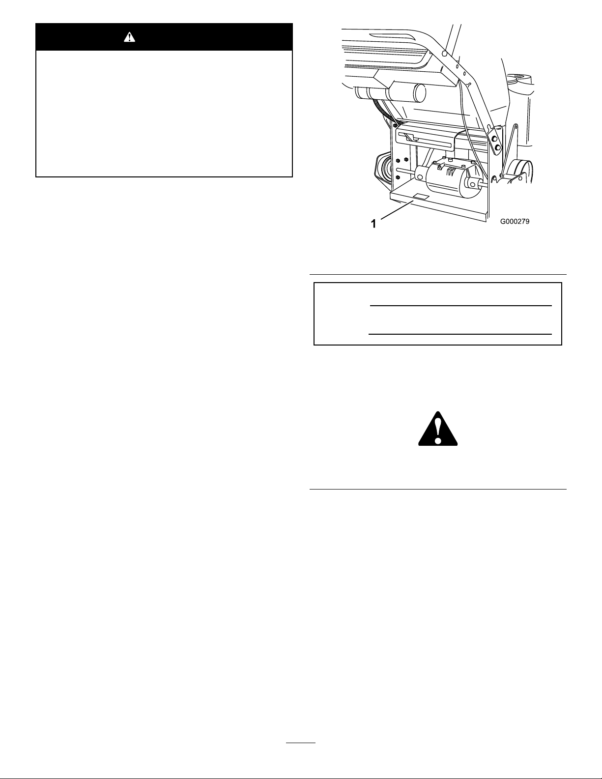
Figure1
1.Modelandserialnumberlocation
Theenclosed
Engine Owner's Man ual
issuppliedfor
informationregardingtheUSEnvironmentalProtection
Agency(EPA)andtheCaliforniaEmissionControl
Regulationofemissionsystems,maintenance,and
warranty.Replacementsmaybeorderedthroughthe
enginemanufacturer.
Introduction
Thisrotary-blade,lawnmowerisintendedtobe
usedbyprofessional,hiredoperatorsorresidential
homeowners.Itisdesignedprimarilyforcuttinggrass
onwell-maintainedlawnsonresidentialorcommercial
properties.Itisnotdesignedforcuttingbrushorfor
agriculturaluses.
Readthisinformationcarefullytolearnhowtooperateand
maintainyourproductproperlyandtoavoidinjuryand
productdamage.Youareresponsibleforoperatingthe
productproperlyandsafely.
YoumaycontactTorodirectlyatwww .T oro.comforproduct
andaccessoryinformation,helpndingadealer,ortoregister
yourproduct.
ModelNo.
SerialNo.
Thismanualidentiespotentialhazardsandhassafety
messagesidentiedbythesafetyalertsymbol(Figure2),
whichsignalsahazardthatmaycauseseriousinjuryordeath
ifyoudonotfollowtherecommendedprecautions.
Figure2
1.Safetyalertsymbol
Thismanualuses2wordstohighlightinformation.
Importantcallsattentiontospecialmechanicalinformation
andNoteemphasizesgeneralinformationworthyofspecial
attention.
Wheneveryouneedservice,genuineT oroparts,oradditional
information,contactanAuthorizedServiceDealerorToro
CustomerServiceandhavethemodelandserialnumbersof
yourproductready.Figure1identiesthelocationofthe
modelandserialnumbersontheproduct.Writethenumbers
inthespaceprovided.
©2014—TheToro®Company
8111LyndaleAvenueSouth
Bloomington,MN55420
Contactusatwww.Toro.com.
2
PrintedintheUSA
AllRightsReserved
Page 3

Contents
Safety...........................................................................4
SafeOperatingPractices...........................................4
ToroMowerSafety..................................................5
SlopeIndicator.......................................................6
SafetyandInstructionalDecals.................................7
ProductOverview.........................................................10
Controls...............................................................11
Specications........................................................12
Attachments/Accessories........................................12
Operation....................................................................12
AddingFuel...........................................................12
CheckingtheEngine-OilLevel.................................13
PuttingSafetyFirst.................................................13
UsingtheParkingBrake..........................................13
StartingandStoppingtheEngine..............................14
OperatingtheMowerPowerTakeOff
(PTO)...............................................................14
TheSafety-InterlockSystem....................................15
DrivingForwardorBackward..................................15
UsingtheLowerControlBar...................................16
StoppingtheMachine.............................................17
TransportingMachines............................................17
SideDischargingorMulchingtheGrass.....................18
AdjustingtheHeight-of-Cut....................................18
AdjustingtheAnti-ScalpRollers...............................18
AdjustingtheHandleHeight....................................19
AdjustingtheFlowBafe........................................20
PositioningtheFlowBafe......................................20
UsingtheMid-SizeWeight.......................................21
Maintenance.................................................................23
RecommendedMaintenanceSchedule(s)......................23
Lubrication...............................................................24
GreasingtheMachine.............................................24
LubricatingtheCasterandWheelBearings.................24
GreasingtheTransmissionCouplers.........................24
GreasingthePTO-Drive-BeltIdlerand
Mower-Deck-BeltIdler........................................24
EngineMaintenance..................................................25
ServicingtheAirCleaner.........................................25
ServicingtheEngineOil..........................................26
ServicingtheSparkPlugs.........................................28
FuelSystemMaintenance...........................................29
DrainingtheFuelTank...........................................29
ReplacingtheFuelFilter..........................................29
ElectricalSystemMaintenance....................................30
ServicingtheFuse..................................................30
DriveSystemMaintenance.........................................30
AdjustingtheControlBar........................................30
CheckingtheTirePressure......................................31
ReplacingtheCaster-Wheel-ForkBushings................31
ServicingtheCasterWheelandBearings....................32
AdjustingtheElectricClutch....................................32
CoolingSystemMaintenance......................................33
CleaningtheAir-IntakeScreen.................................33
BrakeMaintenance....................................................34
ServicingtheBrakes................................................34
BeltMaintenance......................................................35
ReplacingtheTraction-DriveBelt.............................35
ReplacingtheTransmissionBelt...............................35
ReplacingtheMowerBelt........................................35
ReplacingthePTO-DriveBelt..................................36
AdjustingthePTO-Drive-Belt-Idler-Spring
Anchor..............................................................37
MowerDeckMaintenance...........................................38
ServicingtheCuttingBlades.....................................38
CorrectingtheMowerQualityofCut........................40
FrameSetup..........................................................41
CheckingtheMowerDeckFront-to-Rear
Pitch.................................................................42
ChangingtheMowerDeckFront-to-Rear
Pitch.................................................................43
CheckingtheMowerDeckSide-to-Side
Height...............................................................43
ChangingtheMowerDeckSide-to-Side
Height...............................................................44
MatchingtheHeight-of-Cut.....................................44
ReplacingtheGrassDeector..................................44
Storage........................................................................46
CleaningandStorage..............................................46
Troubleshooting...........................................................47
Schematics...................................................................49
3
Page 4

Safety
Note:Theadditionofattachmentsmadebyother
manufacturersthatdonotmeetAmericanNationalStandards
Institutecerticationwillcausenoncomplianceofthis
machine.
Improperuseormaintenancebytheoperatororownercan
resultininjury.Toreducethepotentialforinjury,comply
withthesesafetyinstructionsandalwayspayattentiontothe
safetyalertsymbol,whichmeansCAUTION,WARNING,
orDANGER-“personalsafetyinstruction."Failuretocomply
withtheinstructionmayresultinpersonalinjuryordeath.
SafeOperatingPractices
ThefollowinginstructionsareadaptedfromANSIstandard
B71.4-2012.
Training
•ReadtheOperator'sManualandothertrainingmaterial.If
theoperator(s)ormechanic(s)cannotreadEnglishitis
theowner'sresponsibilitytoexplainthismaterialtothem.
•Becomefamiliarwiththesafeoperationoftheequipment,
operatorcontrols,andsafetysigns.
•Alloperatorsandmechanicsshouldbetrained.The
ownerisresponsiblefortrainingtheusers.
•Neverletchildrenoruntrainedpeopleoperateorservice
theequipment.Localregulationsmayrestricttheageof
theoperator.
•Theowner/usercanpreventandisresponsiblefor
accidentsorinjuriesoccurringtohimselforherself,other
peopleorproperty.
Preparation
•Evaluatetheterraintodeterminewhataccessoriesand
attachmentsareneededtoproperlyandsafelyperform
thejob.Onlyuseaccessoriesandattachmentsapproved
bythemanufacturer.
•Wearappropriateclothingincludinghardhat,safety
glassesandhearingprotection.Longhair,looseclothing
orjewelrymaygettangledinmovingparts.
•Inspecttheareawheretheequipmentistobeusedand
removeallobjectssuchasrocks,toysandwirewhichcan
bethrownbythemachine.
•Checkthatoperator'spresencecontrols,safetyswitches
andshieldsareattachedandfunctioningproperly.Donot
operateunlesstheyarefunctioningproperly.
•Neverrunanengineinanenclosedarea.
•Onlyoperateingoodlight,keepingawayfromholesand
hiddenhazards.
•Besurealldrivesareinneutralandparkingbrakeis
engagedbeforestartingengine.Onlystartenginefrom
theoperator'sposition.
•Besureofyourfootingwhileusingthismachine,
especiallywhenbackingup.Walk,don'trun.Never
operateonwetgrass.Reducedfootingcouldcause
slipping.
•Slowdownanduseextracareonhillsides.Besureto
travelsidetosideonhillsides.Turfconditionscanaffect
themachine'sstability .Usecautionwhileoperatingnear
drop-offs.
•Slowdownandusecautionwhenmakingturnsandwhen
changingdirectionsonslopes.
•Neverraisedeckwiththebladesrunning.
•NeveroperatewiththePTOshield,orotherguardsnot
securelyinplace.Besureallinterlocksareattached,
adjustedproperly ,andfunctioningproperly.
•Neveroperatewiththedischargedeectorraised,
removedoraltered,unlessusingagrasscatcher.
•Donotchangetheenginegovernorsettingoroverspeed
theengine.
•Stoponlevelground,disengagedrives,engageparking
brake(ifprovided),shutoffenginebeforeleavingthe
operator'spositionforanyreasonincludingemptyingthe
catchersoruncloggingthechute.
•Stopequipmentandinspectbladesafterstrikingobjects
orifanabnormalvibrationoccurs.Makenecessary
repairsbeforeresumingoperations.
•Keephandsandfeetawayfromthecuttingunit.
•Lookbehindanddownbeforebackinguptobesureof
aclearpath.
•Keeppetsandbystandersaway .
•Slowdownandusecautionwhenmakingturnsand
crossingroadsandsidewalks.Stopbladesifnotmowing.
•Beawareofthemowerdischargedirectionanddonot
pointitatanyone.
•Donotoperatethemowerundertheinuenceofalcohol
ordrugs.
•Usecarewhenloadingorunloadingthemachineinto
orfromatrailerortruck.
•Usecarewhenapproachingblindcorners,shrubs,trees,
orotherobjectsthatmayobscurevision.
•Lightningcancausesevereinjuryordeath.Iflightning
isseenorthunderisheardinthearea,donotoperate
themachine;seekshelter.
Operation
•Lightningcancausesevereinjuryordeath.Iflightning
isseenorthunderisheardinthearea,donotoperate
themachine;seekshelter.
SafeHandlingofFuels
•Toavoidpersonalinjuryorpropertydamage,use
extremecareinhandlinggasoline.Gasolineisextremely
ammableandthevaporsareexplosive.
4
Page 5

•Extinguishallcigarettes,cigars,pipes,andothersources
ofignition.
•Useonlyanapprovedfuelcontainer.
•Neverremovefuelcaporaddfuelwiththeengine
running.
•Allowenginetocoolbeforerefueling.
•Neverrefuelthemachineindoors.
•Neverstorethemachineorfuelcontainerwherethereis
anopename,spark,orpilotlightsuchasonawater
heateroronotherappliances.
•Neverllcontainersinsideavehicleoronatruckor
trailerbedwithaplasticliner.Alwaysplacecontainerson
thegroundawayfromyourvehiclebeforelling.
•Removeequipmentfromthetruckortrailerandrefuelit
ontheground.Ifthisisnotpossible,thenrefuelsuch
equipmentwithaportablecontainer,ratherthanfroma
fueldispensernozzle.
•Keepthenozzleincontactwiththerimofthefueltank
orcontaineropeningatalltimesuntilfuelingiscomplete.
Donotuseanozzlelockopendevice.
•Iffuelisspilledonclothing,changeclothingimmediately.
•Neveroverllfueltank.Replacefuelcapandtighten
securely.
MaintenanceandStorage
•Disengagedrives,setparkingbrake,stopengineand
removekeyordisconnectsparkplugwire.Waitforall
movementtostopbeforeadjusting,cleaningorrepairing.
•Cleangrassanddebrisfromcuttingunit,drives,mufers,
andenginetohelppreventres.Cleanupoilorfuel
spillage.
•Letenginecoolbeforestoringanddonotstorenear
ame.
•Shutofffuelwhilestoringortransporting.Donotstore
fuelnearamesordrainindoors.
•Parkmachineonlevelground.Setparkingbrake.Never
allowuntrainedpersonneltoservicemachine.
•Usejackstandstosupportcomponentswhenrequired.
•Carefullyreleasepressurefromcomponentswithstored
energy.
•Disconnectthebatteryorremovesparkplugwirebefore
makinganyrepairs.Disconnectthenegativeterminalrst
andthepositivelast.Reconnectthepositiverstand
negativelast.
•Usecarewhencheckingblades.Wraptheblade(s)or
weargloves,andusecautionwhenservicingthem.Only
replaceblades.Neverstraightenorweldthem.
•Keephandsandfeetawayfrommovingparts.Ifpossible,
donotmakeadjustmentswiththeenginerunning.
•Keepallpartsingoodworkingconditionandallhardware
tightened.Replaceallwornordamageddecals.
Hauling
•Usecarewhenloadingorunloadingthemachineintoa
trailerortruck.
•Usefullwidthrampsforloadingmachineintotraileror
truck.
•Tiethemachinedownsecurelyusingstraps,chains,cable,
orropes.Bothfrontandrearstrapsshouldbedirected
downandoutwardfromthemachine.
ToroMowerSafety
ThefollowinglistcontainssafetyinformationspecictoToro
productsandothersafetyinformationyoumustknow.
Thisproductiscapableofamputatinghandsandfeetand
throwingobjects.Alwaysfollowallsafetyinstructionsto
avoidseriousinjuryordeath.
Thisproductisdesignedforcuttingandrecyclinggrassor,
whenequippedwithagrassbagger,forcatchingcutgrass.
Anyuseforpurposesotherthanthesecouldprovedangerous
touserandbystanders.
GeneralOperation
•Besuretheareaisclearofotherpeoplebeforemowing.
Stopthemachineifanyoneentersthearea.
•Donottouchequipmentorattachmentpartswhichmay
behotfromoperation.Allowtocoolbeforeattempting
tomaintain,adjustorservice.
•UseonlyToroapprovedattachments.Warrantymaybe
voidedifusedwithunapprovedattachments.
•Checkcarefullyforoverheadclearances(i.e.branches,
doorways,electricalwires)beforeoperatingunderany
objectsanddonotcontactthem.
SlopeOperation
Allslopesandrampsrequireextracaution.Ifyoufeeluneasy
onaslope,donotmowit.
•Removeobstaclessuchasrocks,treelimbs,etc.fromthe
mowingarea.
•Watchforholes,rutsorbumps.Tallgrasscanhide
obstacles.
•Usecautionneardrop-offs,ditches,orembankments.
Themachinecouldsuddenlyturnoverifawheelgoes
overtheedgeofaclifforditch,orifanedgecavesin.
•Useextracarewithgrasscatchersorotherattachments.
Thesecanchangethestabilityofthemachine.
•Keepallmovementonslopesslowandgradual.Donot
makesuddenchangesinspeedordirection.
•Mowslopessidetoside.
•Donotmowslopesgreaterthan20degrees.
5
Page 6
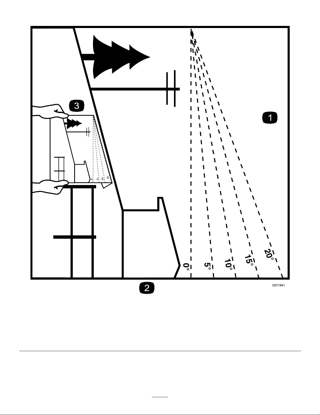
SlopeIndicator
G011841
Figure3
Thispagemaybecopiedforpersonaluse.
1.Themaximumslopeyoucansafelyoperatethemachineonis20degrees.Usetheslopecharttodeterminethedegreeofslope
ofhillsbeforeoperating.Donotoperatethismachineonaslopegreaterthan20degrees.Foldalongtheappropriateline
tomatchtherecommendedslope.
2.Alignthisedgewithaverticalsurface,atree,building,fencepole,etc.
3.Exampleofhowtocompareslopewithfoldededge.
6
Page 7
SafetyandInstructionalDecals
Safetydecalsandinstructionsareeasilyvisibletotheoperatorandarelocatednearanyareaofpotential
danger.Replaceanydecalthatisdamagedorlost.
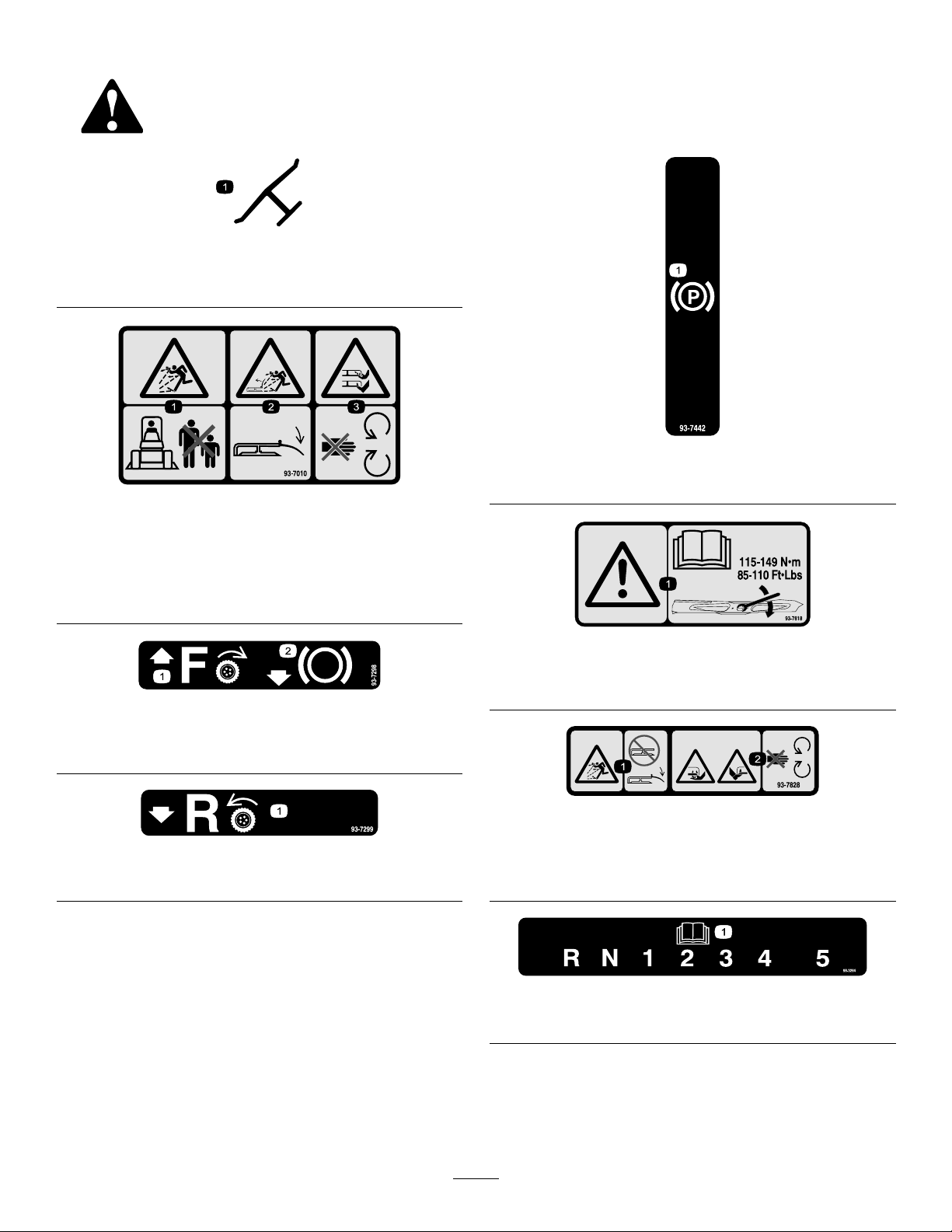
Manufacturer'sMark
1.Indicatesthebladeisidentiedasapartfromtheoriginal
machinemanufacturer.
93-7010
93-7442
1.Parkingbrake
1.Thrownobjecthazard—keepbystandersasafedistance
fromthemachine.
2.Thrownobjecthazard,mower—keepthedeectorinplace.
3.Cutting/dismembermentofhandorfoot—stayawayfrom
movingparts.
93-7298
1.Tractiondrive—forward
2.Pulltobrake
93-7299
1.Tractiondrive—reverse
93-7818
1.Warning—readtheOperator'sManualforinstructionson
torquingthebladebolt/nutto115-149N-m(85-110ft-lb).
93-7828
1.Thrownobjecthazard,mower—keepthedeectorinplace.
2.Cutting/dismembermentofhandorfoot—stayawayfrom
movingparts.
1.ReadtheOperator'sManual.
7
98-3264
Page 8
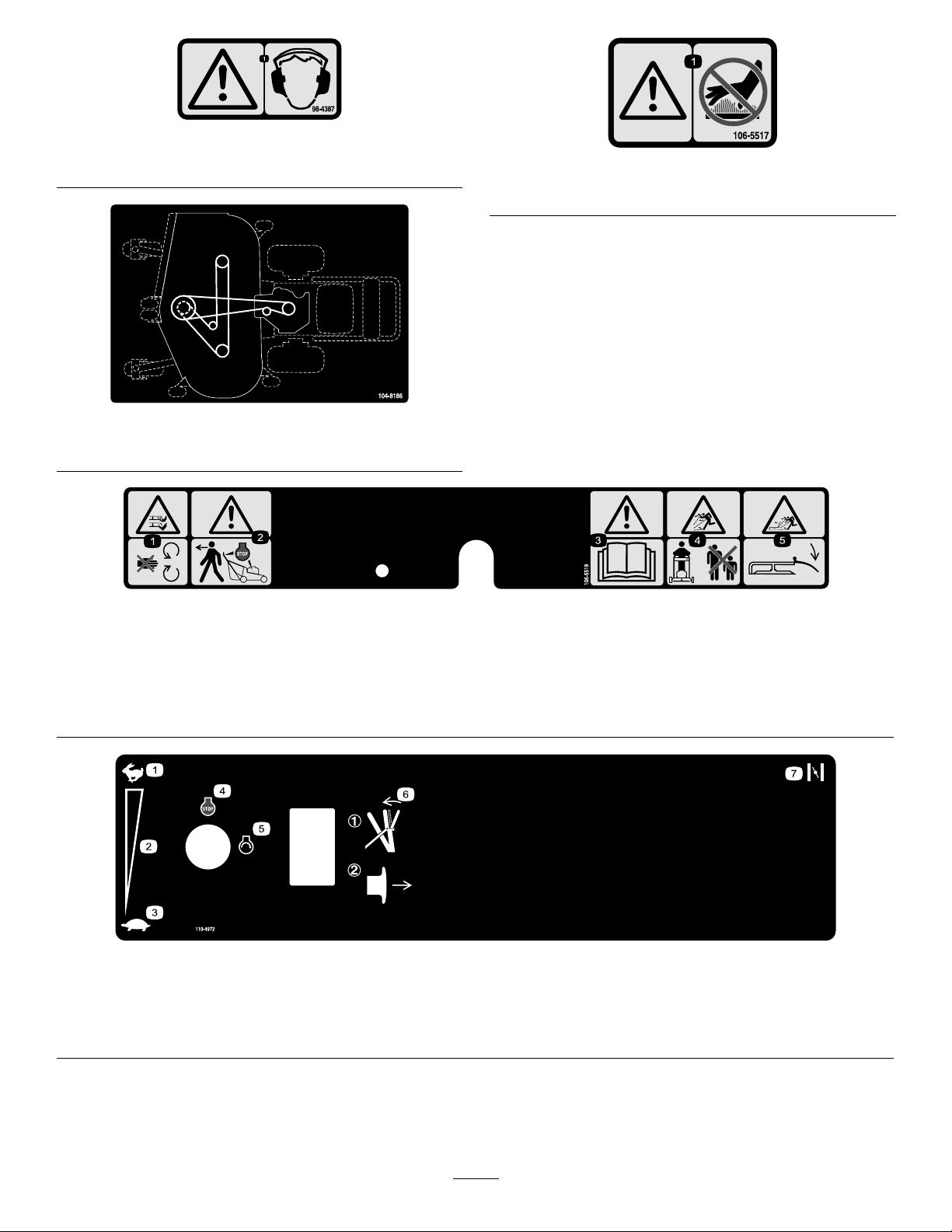
98-4387
1.Warning—wearhearingprotection.
106-5517
1.Warning—donottouchthehotsurface.
104-8186
48inchmower
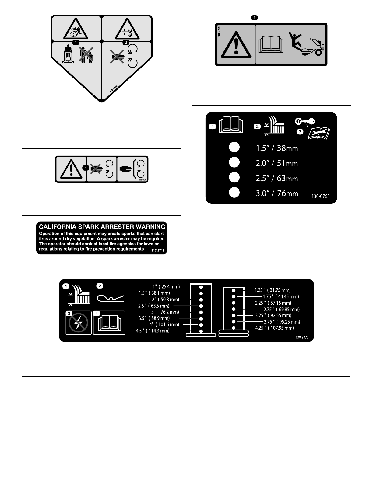
106-5519
1.Severinghazardofhandorfoot,mower
blade—stayawayfrommovingparts.
2.Warning—releasethebarandensure
theenginehasstoppedbeforewalking
awayfromthemachine.
1.Fast
2.Continuousvariablesetting4.Engine—Stop
3.Warning—readtheOperator'sManual.
4.Thrownobjecthazard—keep
bystandersawayfromthemachine.
5.Thrownobjecthazard,raised
bafe—lowerthebafebeforeusing
themachine.
110-4972
3.Slow5.Engine—Start7.Choke
6.Engagebalethenpullout
onthePTOtoengagethe
blade.
8
Page 9
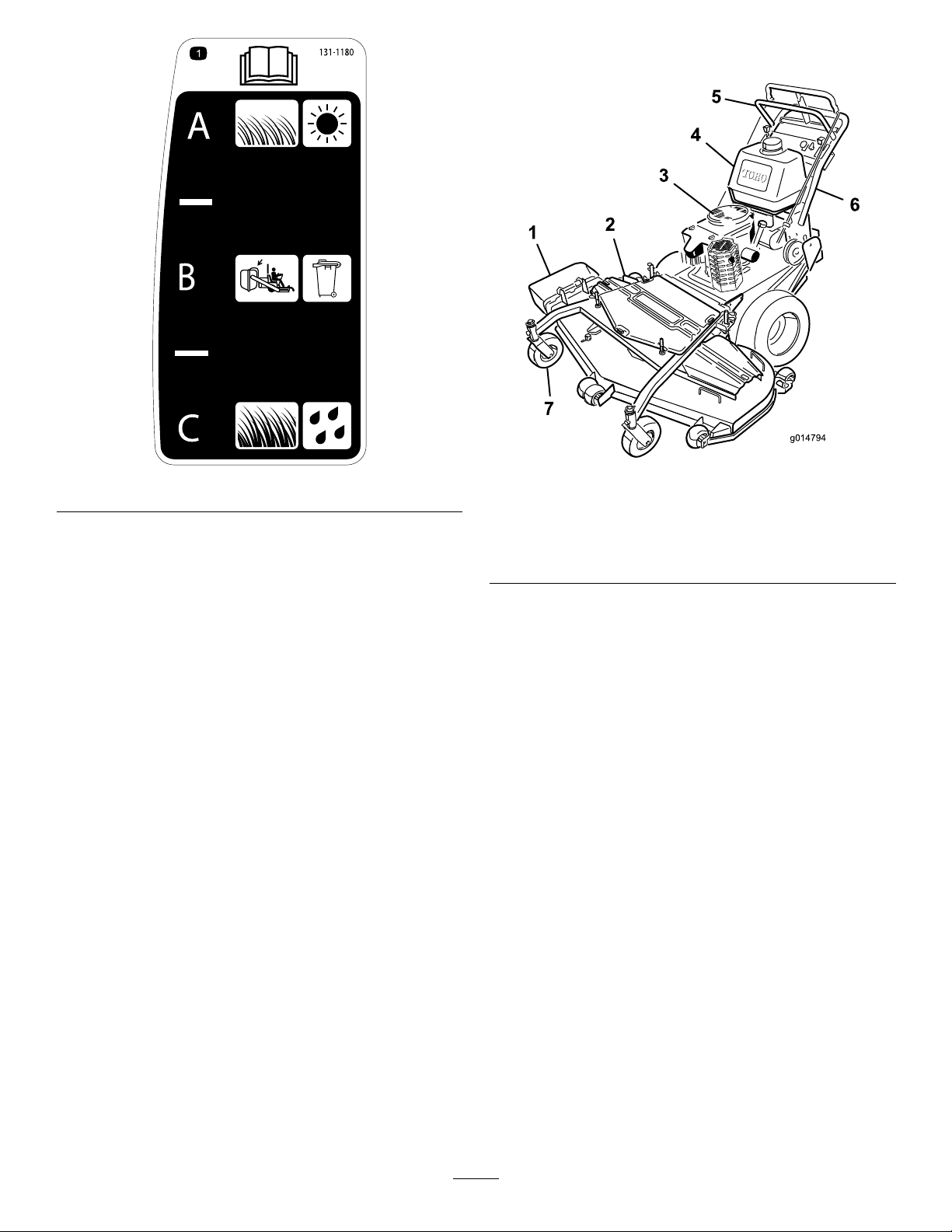
112-8760
1.Thrownobjecthazard—keepbystandersasafedistance
fromthemachine.
2.Cutting/dismembermentofhandorfoot—stayawayfrom
movingparts.
112-9028
1.Warning—stayawayfrommovingparts;keepallguardsin
place.
126-1400
1.Warning-ReadtheOperator’smanual.UseonlyTororiding
attachments.Useofotherridingattachmentsmaycreatea
hazardousconditionresultingininjury.
130-0765
1.ReadtheOperator's
Manual.
2.Height-of-cutselection
117–2718
130-8372
1.Height-of-cut3.Turnoffpowerbeforechangingheight-of-cut.
2.Hairpincotter
4.ReadtheOperator'sManual.
3.Removethekeyfrom
theignitionandreadthe
Operator'sManualbefore
permorningmaintenance.
9
Page 10
ProductOverview
g014794
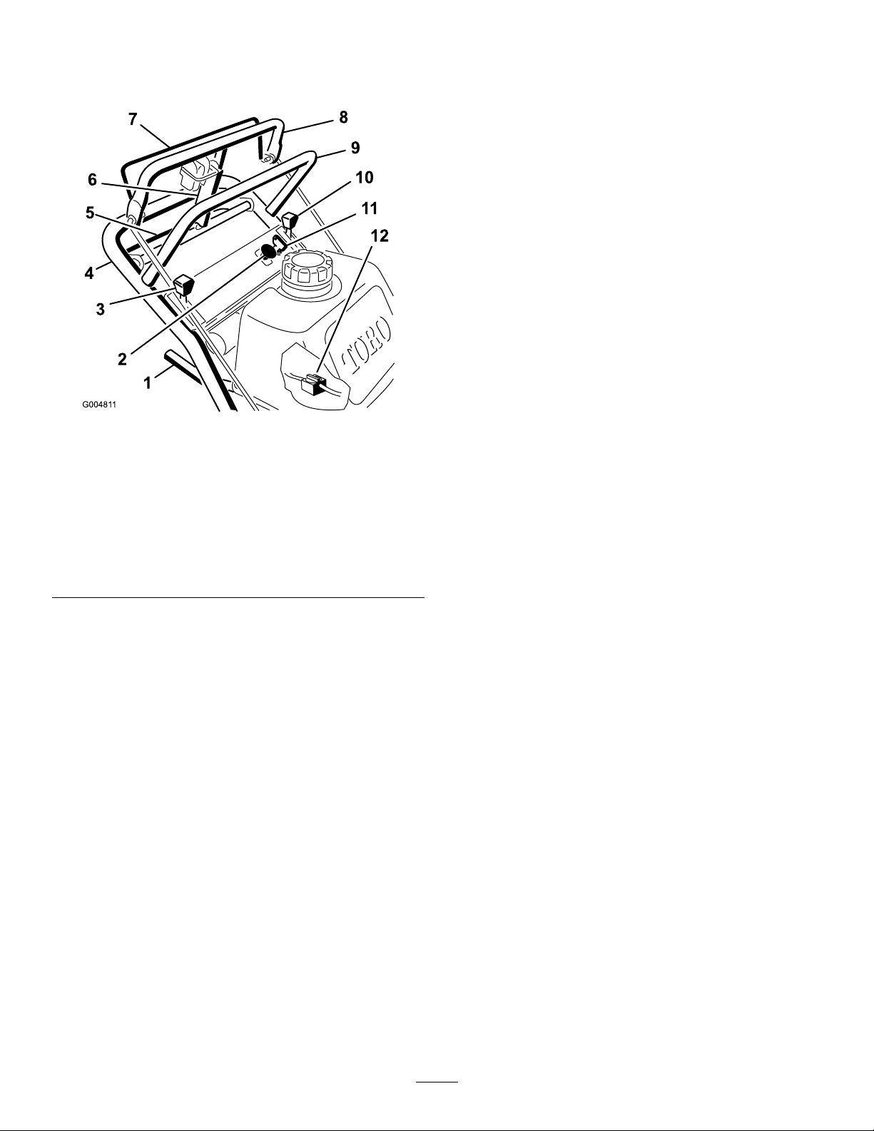
131-1180
Figure4
1.Sidedischargechute5.Controls
2.Mowerdeck6.Handle
3.Recoilstarter
4.Gastank
7.Casterwheel
10
Page 11
Controls
UpperControlBar
Becomefamiliarwithallthecontrols(Figure5)beforeyou
starttheengineandoperatethemachine.
Figure5
1.Gearshiftlever
2.Powertakeoffswitch
(PTO)
3.Chokecontrol
4.Lowerhandle10.Throttlecontrol
5.Lowercontrolbar11.Ignitionswitch
6.Parkingbrake
lever-releasedposition
7.Bladecontrolbail
8.Uppercontrolbar
9.Upperhandle
12.Fuelshut-offvalve
Shifttothedesiredgearandpushforwardontheupper
controlbartoengageforwardtractionoperationandpull
backtobrakeforwardmovement.Pullbackonrightsideof
uppercontrolbartoturnrightandleftsidetoturnleft.
LowerControlBar
Shifttransmissiontoreverseandsqueezethelowercontrol
barandhandletogethertoengagerearwardtractionassist
operation.
Parking-BrakeLever
Pullbackonuppercontrolbarandswingbrakeleverup
againsttheupperhandle(Figure5).
IgnitionSwitch
Thisswitchisusedinconjunctionwithrecoilstarterandhas
twopositions:RunandOff.
RecoilStarter
Pullrecoilstarterhandletostartengine(notshowninFigure
5).
Fuel-ShutoffValve
Closethefuel-shutoffvalvewhentransportingorstoring
mower.
ThrottleControl
Thethrottlecontrolhastwopositions:FastandSlow.
Choke
Usethechoketostartacoldengine.
Blade-ControlBail
Thebailisusedinconjunctionwiththepower-takeoffswitch
(PTO)toengagetheclutchtodrivethemowerblades.
Releasetheblade-controlbailtodisengagethemowerblades.
Power-TakeoffSwitch(PTO)
Thispullswitchisusedinconjunctionwiththebladecontrol
bailtoengagetheclutchtodrivethemowerblades.
Gear-ShiftLever
Thetransmissionhasveforwardspeeds,neutralandreverse,
andhasanin-lineshiftpattern.
Important:Donotshiftwhileunitismoving,as
transmissiondamagemayoccur.
11
Page 12

Specications
Note:Specicationsanddesignaresubjecttochange
withoutnotice.
36inchMowers
Operation
Note:Determinetheleftandrightsidesofthemachine
fromthenormaloperatingposition.
Widthwithdeectordown130cm(51–1/8inches)
Length
Heightwithhandleinlowest
position
Weight
210cm(82–3/4inches)
105cm(41–3/16inches)
267kg(588lb)
48inchMowers
Widthwithdeectordown161cm(63–1/2inches)
Length
Heightwithhandleinlowest
position
Weight
208cm(82inches)
105cm(41–3/16inches)
294kg(649lb)
Attachments/Accessories
AselectionofToroapprovedattachmentsandaccessoriesis
availableforusewiththemachinetoenhanceandexpand
itscapabilities.ContactyourAuthorizedServiceDealeror
Distributororgotowww .Toro.comforalistofallapproved
attachmentsandaccessories.
AddingFuel
•Forbestresults,useonlyclean,fresh(lessthan30days
old),unleadedgasolinewithanoctaneratingof87or
higher((R+M)/2ratingmethod).
•Ethanol:Gasolinewithupto10%ethanol(gasohol)
or15%MTBE(methyltertiarybutylether)byvolume
isacceptable.EthanolandMTBEarenotthesame.
Gasolinewith15%ethanol(E15)byvolumeisnot
approvedforuse.Neverusegasolinethatcontains
morethan10%ethanolbyvolume,suchasE15
(contains15%ethanol),E20(contains20%ethanol),or
E85(containsupto85%ethanol).Usingunapproved
gasolinemaycauseperformanceproblemsand/orengine
damagewhichmaynotbecoveredunderwarranty.
•Donotusegasolinecontainingmethanol.
•Donotstorefueleitherinthefueltankorfuelcontainers
overthewinterunlessafuelstabilizerisused.
•Donotaddoiltogasoline.
DANGER
Incertainconditions,gasolineisextremely
ammableandhighlyexplosive.Areorexplosion
fromgasolinecanburnyouandothersandcan
damageproperty.
•Fillthefueltankoutdoors,inanopenarea,
whentheengineiscold.Wipeupanygasoline
thatspills.
•Neverllthefueltankinsideanenclosedtrailer.
•Donotllthefueltankcompletelyfull.Add
gasolinetothefueltankuntilthelevelis6to13
mm(1/4to1/2inch)belowthebottomofthe
llerneck.Thisemptyspaceinthetankallows
gasolinetoexpand.
•Neversmokewhenhandlinggasoline,andstay
awayfromanopenameorwheregasoline
fumesmaybeignitedbyaspark.
•Storegasolineinanapprovedcontainerand
keepitoutofthereachofchildren.Neverbuy
morethana30-daysupplyofgasoline.
•Donotoperatewithoutentireexhaustsystemin
placeandinproperworkingcondition.
12
Page 13
DANGER
Incertainconditionsduringfueling,static
electricitycanbereleasedcausingasparkwhich
canignitethegasolinevapors.Areorexplosion
fromgasolinecanburnyouandothersandcan
damageproperty.
•Alwaysplacegasolinecontainersontheground
awayfromyourvehiclebeforelling.
•Donotllgasolinecontainersinsideavehicleor
onatruckortrailerbedbecauseinteriorcarpets
orplastictruckbedlinersmayinsulatethe
containerandslowthelossofanystaticcharge.
•Whenpractical,removegas-poweredequipment
fromthetruckortrailerandrefueltheequipment
withitswheelsontheground.
•Ifthisisnotpossible,thenrefuelsuch
equipmentonatruckortrailerfromaportable
container,ratherthanfromagasolinedispenser
nozzle.
•Ifagasolinedispensernozzlemustbeused,
keepthenozzleincontactwiththerimofthe
fueltankorcontaineropeningatalltimesuntil
fuelingiscomplete.
ofvarnishdepositsinthefuelsystem,usefuelstabilizer
atalltimes.
FillingtheFuelTank
1.Shuttheengineoffandsettheparkingbrake.
2.Cleanaroundthefueltankcapandremovethecap.
Addunleadedregulargasolinetothefueltank,untilthe
levelis6to13mm(1/4to1/2inch)belowthebottom
ofthellerneck.Thisspaceinthetankallowsthe
gasolinetoexpand.Donotllthefueltankcompletely
full.
3.Installthefueltankcapsecurely.Wipeupanygasoline
thatmayhavespilled.
CheckingtheEngine-OilLevel
Beforeyoustarttheengineandusethemachine,checktheoil
levelintheenginecrankcase;refertoCheckingOilLevelin
EngineMaintenance(page25)
Note:Determinetheleftandrightsidesofthemachine
fromthenormaloperatingposition.
PuttingSafetyFirst
WARNING
Gasolineisharmfulorfatalifswallowed.Long-term
exposuretovaporscancauseseriousinjuryand
illness.
•Avoidprolongedbreathingofvapors.
•Keepfaceawayfromnozzleandgastankor
conditionerbottleopening.
•Avoidcontactwithskin;washoffspillagewith
soapandwater.
UsingStabilizer/Conditioner
Useafuelstabilizer/conditionerinthemachinetoprovide
thefollowingbenets:
•Keepsgasolinefreshduringstorageof90daysorless.
Forlongerstorageitisrecommendedthatthefueltank
bedrained.
•Cleanstheenginewhileitruns
•Eliminatesgum-likevarnishbuildupinthefuelsystem,
whichcauseshardstarting
Important:Donotusefueladditivescontaining
methanolorethanol.
Addthecorrectamountofgasstabilizer/conditionerto
thegas.
Note:Afuelstabilizer/conditionerismosteffective
whenmixedwithfreshgasoline.Tominimizethechance
Carefullyreadallthesafetyinstructionsanddecalsinthe
safetysection.Knowingthisinformationcouldhelpyouor
anybystandersavoidinjury.
Theuseofprotectiveequipmentforeyes,hearing,feetand
headisrecommended.
CAUTION
Thismachineproducessoundlevelsinexcessof
85dBAattheoperator'searandcancausehearing
lossthroughextendedperiodsofexposure.
Wearhearingprotectionwhenoperatingthis
machine.
Figure6
1.Warning—wearhearingprotection.
UsingtheParkingBrake
Stoponlevelground,disengagedrives,engageparkingbrake,
shutoffengine,andremovekey.Alwayssettheparkingbrake
whenyoustopthemachineorleaveitunattended.
13
Page 14
SettingtheParkingBrake
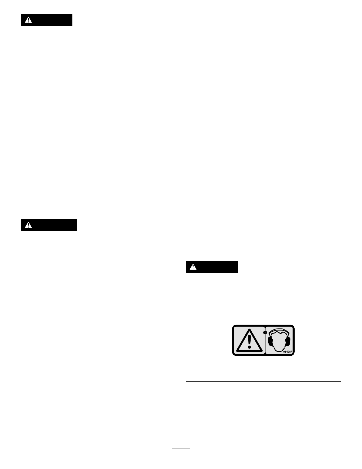
1.Pulltheuppercontrolbar(Figure7)rearwardandhold
itinthisposition.
2.Lifttheparkingbrakelock(Figure7)upandgradually
releasetheuppercontrolbar.Thebrakelockshould
stayintheset(locked)position.
Figure7
1.Uppercontrolbar3.Fixedbar
2.Parkingbrakelever-set
position
StoppingtheEngine
1.Movethethrottlelevertotheslowposition(Figure8).
2.Letengineidlefor30to60secondsbeforeturningthe
ignitionkeytooff.
3.Turntheignitionkeytooff(Figure8).
Figure8
ReleasingtheParkingBrake
1.Pullrearwardontheuppercontrolbar.
2.Lowertheparkingbrakelocktothereleasedposition.
3.Graduallyreleasetheuppercontrolbar.
StartingandStoppingthe Engine
StartingtheEngine
1.Makesurethatthesparkplugwire(s)areinstalledon
thesparkplug(s)andthefuelvalveisopen.
2.Movetheshiftlevertoneutral,settheparkingbrake,
andturnignitionkeytorun.
3.Movethethrottlecontroltothefastpositionandmove
thechokelevertotheonpositionbeforestartinga
coldengine.
Note:Awarmorhotengineusuallydoesnotrequire
anychoking.Tostartawarmengine,movethrottle
controltothefastposition.
4.Grasptherecoilstarterhandlermlyandpullout
untilpositiveengagementresults;thenpullthehandle
vigorouslytostarttheengineandallowtheropeto
recoilslowly .
Important:Donotpulltherecoilropetoits
limitorletgoofthestarterhandlewhentherope
ispulledoutbecausetheropemaybreakorthe
recoilassemblymaybecomedamaged.
1.Throttlelever2.Ignitionkey
4.Settheparkingbrakeandremovethekey.
5.Pullthewireoffofthesparkplug(s)topreventthe
possibilityofaccidentalstartingoftheenginebefore
storingthemachine.
6.Closethefuelshutoffvalvebeforestoringthemachine.
Important:Makesurethatthefuelshutoff
valveisclosedbeforetransportingorstoringthe
machine,asfuelleakagemayoccur.
OperatingtheMowerPower TakeOff(PTO)
Thepowertakeoffswitch(PTO)inconjunctionwiththe
bladecontrolbailengagesanddisengagespowertothe
electricclutchandmowerblades.
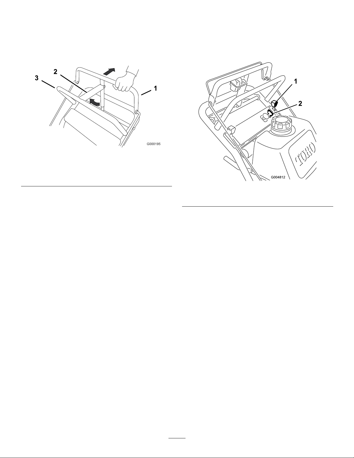
EngagingtheMowerBlades(PTO)
1.Releasetheuppercontrolbartostopthemachine
(Figure9).
2.Toengagetheblades,squeezethebladecontrolbail
againsttheuppercontrolbar(Figure9).
3.Pullthepowertakeoffswitch(PTO)upandreleaseit.
Note:Holdthebladecontrolbailagainsttheupper
controlbarwhileoperatingthemachine.
4.Repeattheproceduretoengagethemowerbladesif
thebladecontrolbailisreleased.
14
Page 15
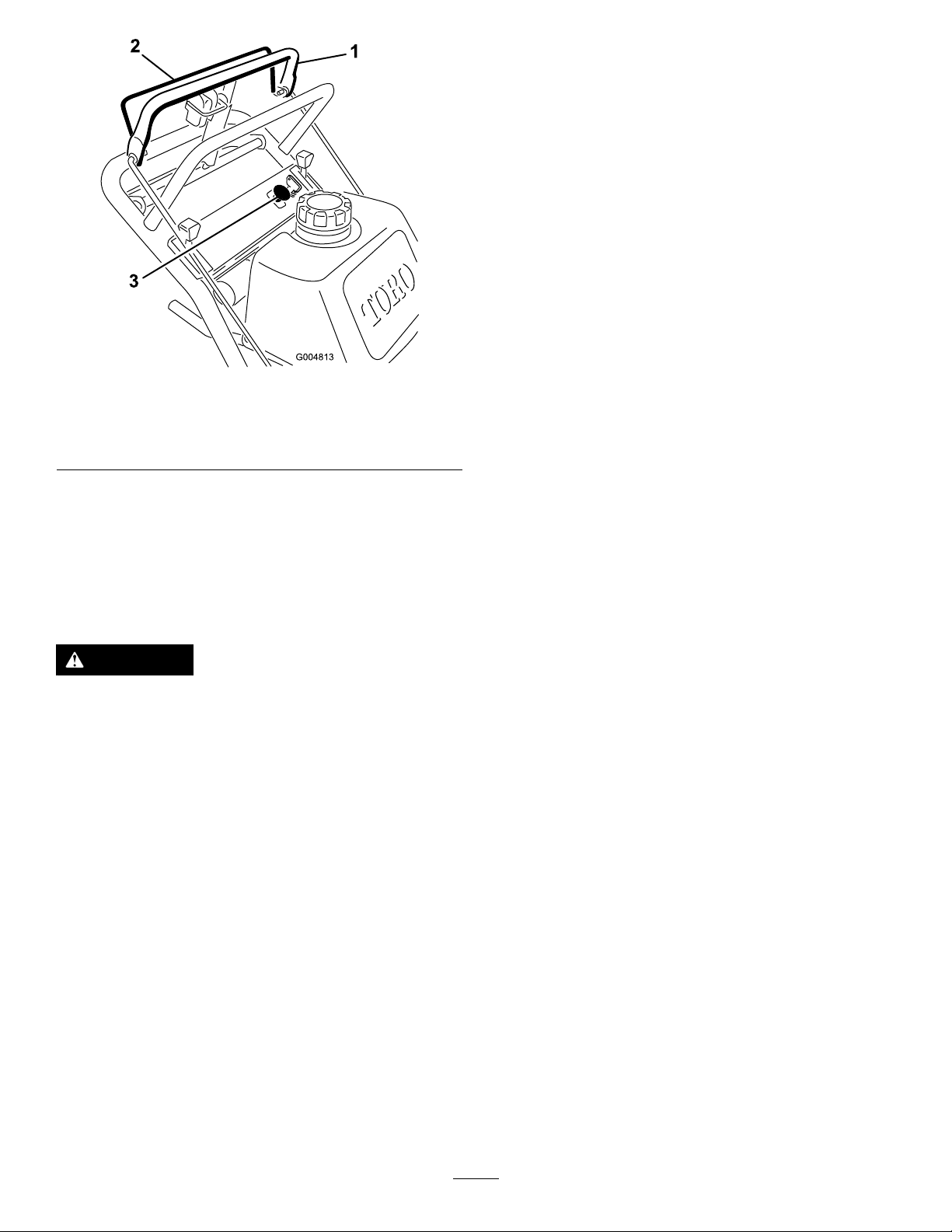
Figure9
1.Uppercontrolbar
2.Bladecontrolbail
3.Powertakeoffswitch
(PTO)
DisengagingtheMowerBlades(PTO)
TestingtheSafety-InterlockSystem
ServiceInterval:Beforeeachuseordaily
Testthesafetyinterlocksystembeforeyouusethemachine
eachtime.
Note:Ifthesafetysystemdoesnotoperateasdescribed
below,haveanAuthorizedServiceDealerrepairthesafety
systemimmediately.
1.Settheparkingbrakeandstarttheengine;referto
StartingandStoppingtheEngine(page14).
2.Squeezetheblade-controlbailagainstuppercontrol
bar.
Note:Thebladesshouldnotrotate.
3.Thencontinueholdingtheblade-controlbailandpull
uponthebladecontrolswitchandrelease.Theclutch
shouldengageandthemowerbladesbeginrotating.
4.Releasetheblade-controlbail.
Note:Thebladesshouldstoprotating.
5.Withtheenginerunning,pullupthepowertakeoff
switch(PTO)andreleasewithoutholdingtheblade
controlbail.Thebladesshouldnotrotate.
Releasethebladecontrolbailtodisengagetheblades(Figure
9).
TheSafety-InterlockSystem
CAUTION
Ifthesafetyinterlockswitchesaredisconnectedor
damagedthemachinecouldoperateunexpectedly
causingpersonalinjury.
•Donottamperwiththeinterlockswitches.
•Checktheoperationoftheinterlockswitches
dailyandreplaceanydamagedswitchesbefore
operatingthemachine.
UnderstandingtheSafety-Interlock
System
Thesafety-interlocksystemisdesignedtopreventthemower
bladesfromrotatingunless:
•Thecontrolbailispressedagainsttheuppercontrolbar.
DrivingForwardorBackward
Thethrottlecontrolregulatestheenginespeedasmeasured
inrpm(revolutionsperminute).Placethethrottlecontrolin
theFastpositionforbestmowingperformance.
DrivingForward
1.Togoforward,movetheshiftlevertoaforwardgear
(Figure10).
2.Releasetheparkingbrake;refertoReleasingthe
ParkingBrake(page14).
3.Slowlypressontheuppercontrolbartomoveforward
(Figure10).
Togostraight,applyequalpressuretobothendsofthe
uppercontrolbar(Figure10).
Toturn,releasepressureontheuppercontrolbarside
inthedirectionyouwanttoturn(Figure10).
•Thepower-takeoffswitch(PTO)ispulledtotheOn
position.
Thesafety-interlocksystemisdesignedtostopthemower
bladesifyoureleasethebladecontrolbail.
15
Page 16
1.Uppercontrolbar
2.Lowercontrolbar
Figure10
3.Shiftlever
DrivingForwardupaCurb
1.Disengagethemowerblades.
2.Selecttherstgeartodrivethemachine.
3.Drivemachineuntilthecasterwheelscontactthecurb
(Figure11).
4.Liftthefrontofthemachinebypushingdownonthe
lowerhandle(Figure11).
5.Drivethemachineuntilthedrivewheelscontactthe
curb(Figure11).
6.Lowerthefrontofthemachine(Figure11).
Note:Bothdrivewheelsshouldcontactthecurband
casterwheelsstraight.
7.Atthesametimeengagethelowercontrolbarandlift
uponthelowerhandletodriveoverthecurb(Figure
10andFigure11).
Note:Liftinguponthelowerhandlewillassistdriving
themachineupacurbandnotspinthedrivewheels.
DrivingBackward
1.Togobackward,movetheshiftlevertoreversegear.
2.Releasetheparkingbrake;refertoReleasingthe
ParkingBrake(page14).
3.Slowlysqueezethelowercontrolbarandlowerhandle
togethertomoverearward(Figure10).
UsingtheLowerControlBar
Thisprocedureisfordrivingupacurb.Thiscanbe
performedwhiledrivingforwardorbackward.
Note:Somecurbsdonotallowthereardrivetirestocontact
thecurb.Ifthishappens,drivethemachineupthecurbatan
angle.
WARNING
Abladecanbebentordamagedwhendrivingup
acurb.Piecesofbladethatmaybethrowncould
seriouslyinjureorkillyouorbystanders.
Donotrunbladeswhiledrivingupacurbforward
orbackward.
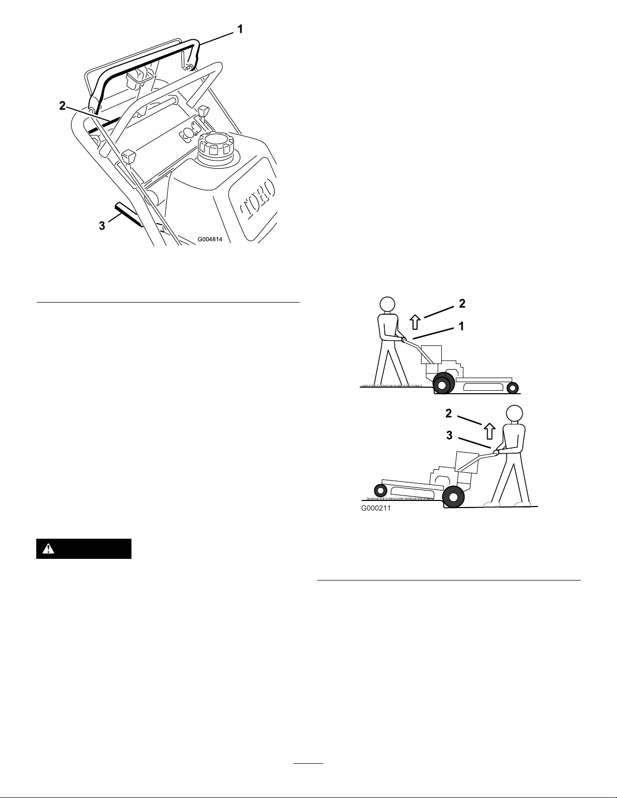
Figure11
1.Lowercontrolbarengaged
andmowerinreverse
2.Pulluptoassistmachine
3.Lowercontrolbarengaged
DrivingBackwardupaCurb
1.Disengagethemowerblades.
2.Selectreversetodrivethemachine.
andmowergoingforward
3.Drivethemachineuntildrivewheelscontactcurb
(Figure11).
Note:Bothdrivewheelsshouldcontactthecurband
casterwheelsstraight.
4.Atthesametimeengagelowercontrolbarandliftup
onthelowerhandle(Figure10andFigure12).
16
Page 17

Note:Liftinguponthelowerhandlewillassistdriving
themachineupacurbandnotspinthedrivewheels.
Figure12
StoppingtheMachine
Tostopthemachine,pullbackontheuppercontrolbar,
releasethebladecontrolbail,andturntheignitionkeyto
off.Alsosettheparkingbrakeifyouleavethemachine
unattended;refertoSettingtheParkingBrakeinSettingthe
ParkingBrake(page14).Remembertoremovethekeyfrom
theignitionswitch.
CAUTION
Childrenorbystandersmaybeinjuredifthey
moveorattempttooperatethemachinewhileitis
unattended.
Alwaysremovetheignitionkeyandsettheparking
brakewhenleavingthemachineunattended,even
ifjustforafewminutes.
1.Lowercontrolbar
(engaged)
2.Handle
TransportingMachines
Useaheavy-dutytrailerortrucktotransportthemachine.
Ensurethatthetrailerortruckhasallnecessarybrakes,
lighting,andmarkingasrequiredbylaw .Pleasecarefullyread
allthesafetyinstructions.Knowingthisinformationcould
helpyou,yourfamily,petsorbystandersavoidinjury.
Totransportthemachine:
1.Ifusingatrailer,connectittothetowingvehicleand
connectthesafetychains.
2.Ifapplicable,connectthetrailerbrakes.
3.Loadthemachineontothetrailerortruck.
4.Stoptheengine,removethekey,setthebrake,and
closethefuelvalve.
5.Usethemetaltiedownloopsonthemachineto
securelyfastenthemachinetothetrailerortruckwith
straps,chains,cable,orropes(Figure13).
1.Tractionunittiedownloop
17
Figure13
Page 18

SideDischargingorMulching theGrass
Thismowerhasahingedgrassdeectorthatdisperses
clippingstothesideanddowntowardtheturf.
DANGER
Withoutthegrassdeector,dischargecover,or
completegrasscatcherassemblymountedin
place,youandothersareexposedtobladecontact
andthrowndebris.Contactwithrotatingmower
blade(s)andthrowndebriswillcauseinjuryor
death.
•Neverremovethegrassdeectorfromthemower
becausethegrassdeectorroutesmaterialdown
towardtheturf.Ifthegrassdeectorisever
damaged,replaceitimmediately .
•Neverputyourhandsorfeetunderthemower.
•Nevertrytocleardischargeareaormower
bladesunlessyoureleasethebailandthepower
takeoff(PTO)isoff.Rotatetheignitionkeyto
Off.Alsoremovethekeyandpullthewire(s)off
thesparkplug(s).
AdjustingtheHeight-of-Cut
Theheight-of-cutcanbeadjustedfrom25to114mm(1to
4-1/2inches)in6mm(1/4inch)increments.Adjustments
aredonebyrelocatingthe4hairpincotterpinsindifferent
holelocationsandbyaddingorremovingspacers.
Note:Allheight-of-cutpinsneedatleast1spacerordamage
canoccurtothebushing.
Note:Allheight-of-cutpinscanuse2spacersmaximum.
1.Selectaholeintheheight-of-cutpostandthenumber
ofspacerscorrespondingtotheheight-of-cutdesired
(Figure14).
2.Usingthelifthandle,raisethesideofthedeckand
removethehairpincotter(Figure14).
3.Addorremovespacersifneededandthenalignthe
holesandinsertthehairpincotter(Figure14).
Note:Thespareheight-of-cutspacersmaybestored
onpostsandretainedbyahairpincotter.
Important:All4hairpincotterpinsmustbeinthe
sameholelocationandwiththecorrectnumberof
spacersforalevelcut.
Figure14
1.Carrierframe4.Spacers
2.Hairpincotter
3.Backheight-of-cutpost
5.Frontheight-of-cutpost
AdjustingtheAnti-Scalp Rollers
Theanti-scalprollersneedtobeadjustedintheproperhole
locationforeachheight-of-cutposition.Thereneedstobe10
mm(3/8inch)minimumclearanceabovetheground.
Note:Iftheanit-scalprollersareadjustedtoolow,itcan
causeexcesswearoftherollers.
1.Afteradjustingtheheight-of-cut,checktheanti-scalp
rollerssothatthereisaminimumof10mm(3/8
inch)clearanceabovetheground(Figure15,Figure
16,Figure17).
2.Ifanadjustmentisneeded,removethebolt,washers,
andnut(Figure15,Figure16,Figure17).
3.Selectaholepositionsothattheanti-scalprollersare
aminimumof10mm(3/8inch)offoftheground
(Figure15,Figure16,Figure17).
4.Installtheboltandnut(Figure15,Figure16,Figure
17).
18
Page 19

Figure17
36inchMowerDeck
Figure15
48inchMowerDecks
1.Mowerdeck4.Anti-scalprollers
2.Bolt5.Nut
3.Spacer
1.Mowerdeck4.Anti-scalprollers
2.Bolt5.Nut
3.Spacer
Note:Incertainmowingconditionsandterrain,a
mismatchofcuttingheightmaybeseen.Adjusting
theoutsideanti-scalprollerstotheminimumsetting
of10mm(3/8inch)willhelppreventthemower
deckcuttingtoolowontheoutsideandminimizethe
mismatch.
AdjustingtheHandleHeight
Thehandlepositioncanbeadjustedtomatchtheoperator's
heightpreference.
1.Removethehairpincotter,washer,andclevispin
securingthecontrolrodttingtotheidlerbracket
(Figure18).
Figure16
48inchMowerDecks
1.Mowerdeck4.Bushing
2.Bolt5.Anti-scalprollers
3.Spacer
6.Nut
Figure18
1.Controlrodandtting
2.Idlerbracket5.Hairpincotter
3.Clevispin6.Rodtting
19
4.Washer
Page 20

2.Loosentheupperangebolts(3/8x1inch)andthe
g012676
1 2
G012677
angenutsecuringthehandletotherearframe(Figure
19).
Figure20
Figure19
1.Upperhandle5.Uppermountinghole
2.Rearframe
3.Flangenut,(3/8inch)
4.Flangebolt,(3/8x1inch)
6.Lowermountingholes
7.Lowposition
8.Highposition
3.Removethelowerangebolts(3/8x1inch)andange
nutssecuringthehandletotherearframe(Figure19).
4.Pivotthehandletothedesiredoperatingpositionand
installthelowerangebolts(3/8x1inch)andthe
angenutsintothemountingholes.Tightenallofthe
angebolts.
5.Checkthecontrolbarforcorrectadjustment.Referto
AdjustingtheControlBarinthemaintenancesection.
6.Checktheparkingbrakeadjustment.RefertoChecking
theBrakesinthemaintenancesection.
AdjustingtheFlowBafe
1.Slot
2.Nut
PositioningtheFlowBafe
Thefollowingguresareonlyrecommendationsforuse.
Adjustmentswillvarybygrasstype,moisturecontent,and
heightofgrass.
Note:Iftheenginepowerdrawsdownandthemower
groundspeedisthesame,openupthebafe.
PositionA
Thisisthefullrearposition(seeFigure21).Thesuggested
useforthispositionisafollows:
•Useforshort,lightgrassmowingconditions.
•Useindryconditions.
•Forsmallergrassclippings.
•Propelsgrassclippingsfartherawayfromthemower.
Themowerdischargeowcanbeadjustedfordifferenttypes
ofmowingconditions.Positionthecamlockandbafeto
givethebestqualityofcut.
1.DisengagethePTO,movethemotioncontrolleversto
theneutrallockedpositionandsettheparkingbrake.
2.Stoptheengine,removethekey,andwaitforallmoving
partstostopbeforeleavingtheoperatingposition.
3.Toadjustthebafe,loosenthenut(Figure20).
4.Adjustthebafeandnutintheslottothedesired
dischargeowandtightenthenut.
Figure21
20
Page 21

PositionB
G012678
G012679
Usethispositionwhenbagging(Figure22).
UsingtheMid-SizeWeight
Weightsareinstalledoncertainmowerstoimprovebalance
andimproveperformance.Theweightscanbemovedor
removedtocreateoptimizedperformanceunderdifferent
mowingconditionsandforoperatorpreference(Figure24
orFigure25).
Thefollowingtableindicatesthepositionoftheweightas
installedatthefactory.
Figure22
PositionC
Thisisthefullopenposition.Thesuggesteduseforthis
positionisasfollows(Figure23):
•Useintall,densegrassmowingconditions.
•Useinwetconditions.
•Lowerstheenginepowerconsumption.
•Allowsincreasedgroundspeedinheavyconditions.
MowerDeckSizeNumberofweights
36inches
48inches2Rear
install
nonenone
Positionofthe
weight
•AnyrearweightmustberemovedwhenaTru-Track
Sulkyisinstalled.
•WhenaTru-Track
®
Sulkyisinstalledfrontweightsare
needed.ContactanAuthorizedServiceDealerforthe
correctquantityofweightsandplacement.
WARNING
Thefrontendofthemachinecanrapidlyriseup
whenthemowerisremoved.Thiscouldcause
seriousinjurytoyouorbystanders.
Supporttherearofthemachinewhenremovingthe
mowerformthecarrierframe.
®
Figure23
Figure24
Installingthefrontweight
1.Bolt3.Weight
2.Washer4.Nut
21
Page 22

Figure25
Installingtherearweight
1.Nut3.Washer
2.Weight4.Bolt
22
Page 23

Maintenance
Note:Determinetheleftandrightsidesofthemachinefromthenormaloperatingposition.
RecommendedMaintenanceSchedule(s)
MaintenanceService
Interval
Aftertherst8hours
Beforeeachuseordaily
Every25hours
Every50hours
Every100hours
Every200hours
MaintenanceProcedure
•Changetheengineoil.
•Checkthesafetyinterlocksystem.
•Greasethecasterwheelsandcasterpivot.
•Checktheengineoillevel.
•Cleantheairintakescreen.
•Checkthebrakesonbothalevelsurfaceandslope.
•Inspecttheblades.
•Cleanthefoamaircleanerelement.
•GreasethePTO-beltidler.
•Greasethemower-deck-beltidler.
•Checkthepaperaircleanerelement.
•Checkthetirepressure
•Checkthetraction-drivebelt
•Checkthetransmissionbelt.
•Checkthemowerbelt.
•CheckthePTO-drivebelt.
•Changetheengineoil.
•Checkthesparkplugs.
•Adjusttheelectricclutch.
•Replacethepaperaircleanerelement.
•Changetheoillter.
•Replacethefuellter.
Every250hours
Every400hours
Beforestorage
•Greasethetransmissioncouplers(moreoftenindirtyordustyconditions).
•Greasethefrontwheelbearings(moreoftenindirtyordustyconditions).
•Paintchippedsurfaces.
•Performallmaintenanceprocedureslistedabovebeforestorage.
Important:Refertoyourengineoperator'smanualforadditionalmaintenanceprocedures.
CAUTION
Ifyouleavethekeyintheignitionswitch,someonecouldaccidentlystarttheengineandseriouslyinjure
youorotherbystanders.
Removethekeyfromtheignitionanddisconnectthesparkplugwiresfromthesparkplugsbeforeyoudo
anymaintenance.Setthewiresasidesothattheydonotaccidentallycontactthesparkplugs.
23
Page 24

Lubrication
GreasewithNo.2generalpurposelithiumbaseor
molybdenumbasegrease.
Note:Makesuretherearwheelgreasecapsare
removedbeforelubricatingrearwheels.
GreasingtheTransmission
GreasingtheMachine
1.DisengagethePTOandsettheparkingbrake.
2.Stoptheengine,removethekey,andwaitforallmoving
partstostopbeforeleavingtheoperatingposition.
3.Cleanthegreasettingswitharag.Makesuretoscrape
anypaintoffthefrontofthetting(s).
4.Connectagreaseguntothetting.Pumpgrease
intothettingsuntilgreasebeginstooozeoutofthe
bearings.
5.Wipeupanyexcessgrease.
LubricatingtheCasterand WheelBearings
ServiceInterval:Beforeeachuseordaily
Every400hours
1.Lubricatethefrontcasterwheelbearingsandfront
pivots(Figure26).
Couplers
ServiceInterval:Every250hours
Lubricatethetransmissioncouplerslocatedinthebackof
themachine(Figure27).
Figure27
Figure26
2.Raisetherearofthemachineandusejackstandsto
supportthemachine.
3.Removetherearwheelandtireassemblies.
4.Removetherearwheelgreasecap.Lubricatetherear
wheelbearing(Figure26).
GreasingthePTO-Drive-Belt IdlerandMower-Deck-Belt Idler
ServiceInterval:Every50hours—GreasethePTO-belt
idler.
Every50hours—Greasethemower-deck-beltidler.
Greasetheidlerpulleypivots(Figure28orFigure29).
Note:Removethecarriercoverstoaccessthegreasetting
forthemowerdeck.
5.Installthegreasecap.
6.Installtherearwheelandtireassembly.
24
Page 25

g014655
Figure28
g014675
48inchMowerDeckshown
EngineMaintenance
ServicingtheAirCleaner
ServiceInterval:Every25hours—Cleanthefoamair
cleanerelement.
Every50hours—Checkthepaperaircleanerelement.
Every200hours—Replacethepaperaircleaner
element.
Note:Servicetheaircleanermorefrequently(everyfew
operatinghours)iftheoperatingconditionsareextremely
dustyorsandy .
Important:Donotoilthefoamorpaperelement.
RemovingtheFoamandPaper
Elements
1.DisengagethePTOandsettheparkingbrake.
Figure29
36inchMowerDeckshown
2.Stoptheengine,removethekey,andwaitforallmoving
partstostopbeforeleavingtheoperatingposition.
3.Cleanaroundtheaircleanertopreventdirtfrom
gettingintotheengineandcausingdamage(Figure30).
Figure30
1.Cover
2.Hoseclamp4.Foamelement
3.Paperelement
4.Unscrewthecoverknobsandremovetheaircleaner
cover(Figure30).
5.Unscrewthehoseclampandremovetheaircleaner
assembly(Figure30).
6.Carefullypullthefoamelementoffthepaperelement
(Figure30).
25
Page 26

CleaningtheFoamAir-CleanerElement
1.Washthefoamelementinliquidsoapandwarmwater.
Whentheelementisclean,rinseitthoroughly .
2.Drytheelementbysqueezingitinacleancloth.
Important:Replacethefoamelementifitistorn
orworn.
ServicingthePaperAir-Cleaner
Element
1.Donotcleanthepaperlter,replaceit(Figure30).
2.Inspecttheelementfortears,anoilylm,ordamageto
therubberseal.
3.Replacethepaperelementifitisdamaged.
InstallingtheFoamandPaperElements
Important:Topreventenginedamage,alwaysoperate
theenginewiththecompletefoamandpaperaircleaner
assemblyinstalled.
1.Carefullyslidethefoamelementontothepaperair
cleanerelement(Figure30).
2.Placetheaircleanerassemblyontotheaircleanerbase
andsecureitwiththe2wingnuts(Figure30).
3.Placetheaircleanercoverintopositionandtighten
thecoverknob(Figure30).
ServicingtheEngineOil
ServiceInterval/Specication
ServiceInterval:Beforeeachuseordaily—Checktheengine
oillevel.
Aftertherst8hours—Changetheengineoil.
Every100hours—Changetheengineoil.
Figure31
CheckingtheEngine-OilLevel
1.Parkthemachineonalevelsurface.
2.DisengagethePTOandsettheparkingbrake.
3.Stoptheengine,removethekey,andwaitforallmoving
partstostopbeforeleavingtheoperatingposition.
4.Cleanaroundtheoildipstick(Figure32)sothatdirt
cannotfallintothellerholeanddamagetheengine.
Figure32
1.Oildipstick
2.Fillertube
Every200hours—Changetheoillter.
Note:Changetheoilmorefrequentlywhentheoperating
conditionsareextremelydustyorsandy.
OilType:Detergentoil(APIserviceSF,SG,SH,SJorSL)
CrankcaseCapacity:58ounces(1.7liter)withthelter
removed;51ounces(1.5liter)withoutthelterremoved
Viscosity:Refertothetable(Figure31).
5.Unscrewtheoildipstickandwipetheendclean(Figure
32).
6.Slidetheoildipstickfullyintothellertube,butdonot
threadontotube(Figure32).
7.Pullthedipstickoutandlookattheend.Iftheoillevel
islow,slowlypouronlyenoughoilintothellertube
toraisetheleveltotheFullmark.
Important:Donotoverllthecrankcasewithoil
andruntheengine;enginedamagecanresult.
26
Page 27

ChangingtheEngineOil
1.Parkthemachinesothatthedrainsideisslightly
lowerthantheoppositesidetoassuretheoildrains
completely.
2.DisengagethePTOandsettheparkingbrake.
3.Stoptheengine,removethekey,andwaitforallmoving
partstostopbeforeleavingtheoperatingposition.
4.Slidethedrainhoseovertheoildrainvalve.
5.Placeapanbelowthedrainhose.Rotateoildrainvalve
toallowoiltodrain(Figure33).
6.Whenoilhasdrainedcompletely,closethedrainvalve.
7.Removethedrainhose(Figure33).
1.Oillter
Figure34
2.Adapter
Note:Disposeoftheusedoilatarecyclingcenter.
Figure33
1.Oildrainvalve2.Oildrainhose
3.Applyathincoatofnewoiltotherubbergasketon
thereplacementlter(Figure34).
4.Installthereplacementoilltertothelteradapter,
turntheoillterclockwiseuntiltherubbergasket
contactsthelteradapter,thentightenthelteran
additional3/4turn(Figure34).
5.Fillthecrankcasewiththepropertypeofnewoil;refer
toServicingtheEngineOil.
6.Runtheengineforabout3minutes,stoptheengine,
andcheckforoilleaksaroundtheoillteranddrain
valve.
7.Checktheengineoillevelandaddoilifneeded.
8.Wipeupanyspilledoil.
8.Slowlypourapproximately80%ofthespeciedoil
intothellertube(Figure32).
9.Checktheoillevel;refertoCheckingtheEngineOil
Level.
10.SlowlyaddtheadditionaloiltobringittotheFull
mark.
ChangingtheOilFilter
Note:Changetheoilltermorefrequentlywhenthe
operatingconditionsareextremelydustyorsandy.
1.Draintheoilfromtheengine;refertoChangingthe
EngineOil.
2.Removetheoldlter(Figure34).
27
Page 28

ServicingtheSparkPlugs
1
ServiceInterval:Every100hours—Checkthesparkplugs.
Ensurethattheairgapbetweenthecenterandsideelectrodes
iscorrectbeforeinstallingthesparkplug.Useasparkplug
wrenchforremovingandinstallingthesparkplugsanda
gappingtool/feelergaugetocheckandadjusttheairgap.
Installanewsparkplugsifnecessary.
Type:Champion®RCJ8YorequivalentAirGap:0.75mm
(0.030inch)
RemovingtheSparkPlugs
1.DisengagethePTOandsettheparkingbrake.
2.Stoptheengine,removethekey,andwaitforallmoving
partstostopbeforeleavingtheoperatingposition.
3.Disconnectthewiresfromthesparkplugs(Figure35).
Figure36
1.Centerelectrodeinsulator3.Airgap(nottoscale)
2.Sideelectrode
Important:Alwaysreplacethesparkplugswhen
ithaswornelectrodes,anoilylmonit,orhas
cracksintheporcelain.
3.Checkthegapbetweenthecenterandsideelectrodes
(Figure36).Bendthesideelectrode(Figure36)ifthe
gapisnotcorrect.
InstallingtheSparkPlugs
1.Installthesparkplugsandthemetalwasher.Ensure
thattheairgapissetcorrectly.
2.Tightenthesparkplugsto22N-m(16ft-lb).
3.Connectthewirestothesparkplugs(Figure36).
Figure35
1.Spark-plugwire/sparkplug
4.Cleanaroundthesparkplugstopreventdirtfrom
fallingintotheengineandpotentiallycausingdamage.
5.Removethesparkplugsandthemetalwashers.
CheckingtheSparkPlugs
1.Lookatthecenterofthesparkplugs(Figure36).If
youseelightbrownorgrayontheinsulator,theengine
isoperatingproperly.Ablackcoatingontheinsulator
usuallymeansthattheaircleanerisdirty.
2.Ifneeded,cleanthesparkplugwithawirebrushto
removecarbondeposits.
28
Page 29

FuelSystem
Maintenance
ReplacingtheFuelFilter
ServiceInterval:Every200hours
Neverinstalladirtylterifitisremovedfromthefuelline.
DrainingtheFuelTank
DANGER
Incertainconditions,gasolineisextremely
ammableandhighlyexplosive.Areorexplosion
fromgasolinecanburnyouandothersandcan
damageproperty.
•Draingasolinefromthefueltankwhenthe
engineiscold.Dothisoutdoorsinanopenarea.
Wipeupanygasolinethatspills.
•Neversmokewhendraininggasoline,andstay
awayfromanopenameorwhereasparkmay
ignitethegasolinefumes.
1.Parkthemachineonalevelsurface,toensurethefuel
tankdrainscompletely .Thendisengagethepowertake
off(PTO),settheparkingbrake,turntheignitionkey
totheOffposition,andremovethekey .
2.Closethefuelshut-offvalveatthefueltank(Figure37).
3.Squeezetheendsofthehoseclamptogetherandslide
itupthefuellineawayfromfuellter(Figure37).
Note:Notehowthefuellterisinstalled.
Note:Wipeupanyspilledfuel.
1.DisengagethePTOandsettheparkingbrake.
2.Stoptheengine,removethekey,andwaitforallmoving
partstostopbeforeleavingtheoperatingposition.
3.Closefuelshut-offvalveatfueltank(Figure37).
Note:Removethefuellinefromthefuelvalvethatis
closesttotheengine.
4.Squeezetheendsofthehoseclampstogetherandslide
themawayfromthelter(Figure38).
4.Pullthefuellineoffthefuellter(Figure37).Open
thefuelshut-offvalveandallowthegasolinetodrain
intoagascanordrainpan.
Note:Nowisthebesttimetoinstallanewfuellter
becausethefueltankisempty.RefertoReplacingthe
FuelFilter.
5.Installthefuellineontothefuellter.Slidethehose
clampclosetothevalvetosecurethefuelline.
Figure37
Figure38
1.Hoseclamp3.Filter
2.Fuelline
5.Removethelterfromthefuellines.
6.Installanewlterandmovethehoseclampscloseto
thelter.
7.Openfuelshut-offvalveatfueltank(Figure37).
8.Checkforfuelleaksandrepairifneeded.
1.Fuelshut-offvalve2.Clamp
29
Page 30

ElectricalSystem
DriveSystem
Maintenance
ServicingtheFuse
Theelectricalsystemisprotectedbyafuse.Itrequiresno
maintenance.Ifthefuseblows,checkthecomponentor
circuitformalfunctionorashort.Toreplacethefuse,pull
outonthefuse(Figure39)toremoveorreplaceit.
Figure39
Maintenance
AdjustingtheControlBar
1.Checkthegapbetweenuppercontrolbarandxed
barwithwheeldrivefullyengaged.Thegapshouldbe
approximately25-32mm(1to1-1/4inch)(Figure40).
Note:Theuppercontrolbarandxedbarmustbe
parallelwhentheuppercontrolbarisintheengaged,
drive,neutral,orbrakepositions.
1.Fuse,7.5amp,bladetype
Figure40
1.Uppercontrolbar4.Handle
2.Parkingbrakelever
3.Fixedcontrolbar
2.Checktheoperation.Ifadjustmentisrequired,remove
thehairpincotter,washer,andclevispinsecuringthe
controlrodttingtoidlerbracket(Figure41).
3.Threadtherodttingupordownontheroduntilthe
properpositionisattainedandinstalltherodtting
totheidlerbracketwiththeclevispin,washer,and
hairpincotter.
5.25-32mm(1to1-1/4inch)
gap
30
Page 31

Replacingthe Caster-Wheel-ForkBushings
Thecasterwheelforksaremountedinbushingspressedinto
thetopandbottomofthecarrierframemountingpivot
tubes.Tocheckthebushings,movethecasterforksbackand
forthandside-to-side.Ifacasterforkisloose,thebushings
arewornandmustbereplaced.
1.Raisethecuttingunitsothatthecasterwheelsareoff
oftheoor,thensupportthefrontofthemowerwith
jackstands.
Figure41
1.Controlrodandtting
2.89mm(3-1/2inch)
3.Idlerbracket
4.Clevispin
5.Washer
6.Hairpincotterpin
7.Rodtting
8.HoleF
CheckingtheTirePressure
ServiceInterval:Every50hours/Monthly(whichever
comesrst)—Checkthetirepressure
Checkthepressureatthevalvestem(Figure42).
Maintaintheairpressureinthereartiresat12-14psi(83-97
kPa).Uneventirepressurecancauseanunevencut.
Note:Thefronttiresaresemi-pneumatictiresanddonot
requireairpressuremaintenance.
2.Removethelockingpinandspacer(s)fromthetopof
thecasterwheelfork(Figure43).
Figure43
1.Lockingpin
2.Spacers4.Casterwheel
3.Carrierframepivottube
Figure42
3.Pullthecasterwheelforkoutofthemountingtube,
leavingthespacer(s)onthebottomofthefork.
Rememberthelocationofthespacersoneachforkto
ensurecorrectinstallation,andtomaintainaleveldeck.
4.Insertapinpunchintothemountingtubeandcarefully
driveoutthebushings(Figure44).Cleantheinsideof
themountingtube.
31
Page 32

Figure44
1.MountingTube2.Bushing
5.Greasetheinsideandoutsideofthenewbushings.Use
ahammerandatplatetocarefullydrivethebushings
intothepivottubes.
6.Inspectthecasterwheelforkforwearandreplaceif
necessary(Figure43).
7.Slidethecasterwheelforkthroughthebushingsinthe
mountingtube.Replacethespacer(s)ontotheforkand
securewiththeretainingring(Figure43).
Important:Theinsidediameterofthebushings
maycollapseslightlywheninstalled.Ifthecaster
wheelforkdoesnotslideintothenewbushings,
reambothbushingstoaninsidediameterof29
mm(1.126inch).
8.Greasethettingonthecarrierframepivottubesusing
No.2generalpurposelithiumbaseormolybdenum
basegrease.
ServicingtheCasterWheel andBearings
Figure45
1.Locknut
2.Cap
3.Rollerbearing6.Bushing
2.Removeonebushing,thenpullthespannerbushing
androllerbearingoutofthewheelhub(Figure45).
3.Removetheotherbushingfromthewheelhuband
cleananygreaseanddirtfromthewheelhub(Figure
45).
4.Inspecttherollerbearing,bushings,spannerbushing,
andinsideofthewheelhubforwear.Replaceany
defectiveorwornparts(Figure45).
5.Toassemble,placeonebushingintothewheelhub.
Greasetherollerbearingandspannerbushingandslide
themintothewheelhub.Placethesecondbushing
intothewheelhub(Figure45).
6.Installthecasterwheelintothecasterforkandsecure
withthewheelboltandlocknut.Tightenthelocknut
untilthespannerbushingbottomsagainsttheinsideof
thecasterforks(Figure45).
7.Greasethettingonthecasterwheel.
4.Spannerbushing
5.Wheel
Thecasterwheelsrotateonarollerbearingsupportedbya
spannerbushing.Ifthebearingiskeptwelllubricated,wear
willbeminimal.Failuretokeepthebearingwelllubricated
willcauserapidwear.Awobblycasterwheelusuallyindicates
awornbearing.
1.Removethelocknutandwheelboltholdingthecaster
wheeltothecasterfork(Figure45).
AdjustingtheElectricClutch
ServiceInterval:Every100hours
Theclutchisadjustabletoensureproperengagementand
properbraking.
1.Inserta0.381–0.533mm(0.015–0.021inch)feeler
gaugethroughoneinspectionslotinthesideofthe
assembly.Makesureitisbetweenthearmatureand
therotorfrictionsurfaces.
2.Tightenthelocknutsuntilthereisaslightbindingon
thefeelergaugebutitcanbemovedeasilywithinthe
airgap(Figure46).
3.Repeatthisfortheremainingslots.
32
Page 33

4.Checkeachslotagainandmakeslightadjustmentsuntil
thefeelergaugebetweentherotorandarmaturewith
veryslightcontactbetweenthem.
Figure46
1.Adjustingnut3.Feelergauge
2.Slot
CoolingSystem
Maintenance
CleaningtheAir-IntakeScreen
ServiceInterval:Beforeeachuseordaily
Removeanybuild-upofgrass,dirt,orotherdebrisfromthe
cylinderandcylinderheadcoolingns,airintakescreenon
ywheelend,andcarburetor-governorleversandlinkage.
Thiswillhelpensureadequatecoolingandcorrectengine
speedandwillreducethepossibilityofoverheatingand
mechanicaldamagetotheengine.
33
Page 34

BrakeMaintenance
ServicingtheBrakes
ServiceInterval:Beforeeachuseordaily—Checkthebrakes
onbothalevelsurfaceandslope.
Alwayssettheparkingbrakewhenyoustopthemachine
orleaveitunattended.Iftheparkingbrakedoesnothold
securely,anadjustmentisrequired.
CheckingtheBrakes
1.Parkthemachineonalevelsurface,disengagethePTO.
2.Stoptheengine,removethekey,andwaitforallmoving
partstostopbeforeleavingtheoperatingposition.
3.Applytheparkingbrake.Thewheelsmustlockwhen
youtrytopushthemachineforward.
4.Ifthewheelsdonotlock,adjustthebrakes.Referto
AdjustingtheBrakes.
5.Releasethebrakeandpressuppercontrolbarvery
lightly,approximately13mm(1/2inch).Thewheels
shouldrotatefreely ,ifnot;refertoAdjustingthe
Brakes.
Figure47
1.Hairpincotterandwasher5.HoleF
2.Trunnion6.Initialadjustment-32mm
(1-1/4inch)
3.Brakelever7.Rod
4.Wingnut
AdjustingtheBrakes
Thebrakeleverisontheuppercontrolbar.Iftheparking
brakedoesnotholdsecurely,anadjustmentisrequired.
Note:Fortheinitialadjustment,adjustthewingnutuntilit
is1-1/4inchesfromthetopoftherod(Figure47).
1.Parkthemachineonalevelsurface,disengagethe
PTO,andsettheparkingbrake.
2.Stoptheengine,removethekey,andwaitforallmoving
partstostopbeforeleavingtheoperatingposition.
3.Checkthebrakebeforeyouadjustit;refertoChecking
theBrakes.
4.Releasetheparkingbrake;refertoReleasingthe
ParkingBrake.
5.Toadjustthebrakeremovethehairpincotterand
washerfromthebrakeleverandtrunnion(Figure47).
6.Rotatethewingnutclockwisetoincreasethebraking
pressure.
7.Rotatethewingnutcounterclockwisetodecreasethe
brakingpressure.
8.InstallthetrunnionintoholeF(Figure47).Tighten
thewingnut.
9.Securetrunniontobrakeleverwithwasherandhair
pincotter(Figure47).
10.Checkthebrakeoperationagain;refertoChecking
theBrakes.
Important:Withtheparkingbrakereleased,the
rearwheelsmustrotatefreelywhenyoupushthe
mower.Ifbrakeactionandfreewheelrotation
cannotbeachievedcontactyourservicedealer
immediately.
34
Page 35

BeltMaintenance
5.Disconnecttheclutchwireconnectorfromthewire
harness.
ReplacingtheTraction-Drive Belt
ServiceInterval:Every50hours/Monthly(whichever
comesrst)—Checkthetraction-drive
belt
Lookforcracks,wear,andsignsofoverheating.
1.Removethetopboltsecuringidlersupportandidler
brackettorearframe(Figure48).
Figure48
1.Topbolt4.Bottombolt
2.Idlerbracket5.Traction-drivebelt
3.Idlersupport
6.Disconnecttheclutchretainerfromtheenginedeck
(Figure49).
Figure49
1.Transmissionbelt
2.Idlerpulley6.Pivotbolt
3.Clutchretainer
4.Tensionspring8.Enginedeck
7.Unhookthetensionspringfromthesideoftheframe
(Figure49).
8.Loosenthepivotboltenoughtoremovethetraction
beltfromthedrivepulleyandclutch.
5.Clutchwireconnector
7.Drivepulley
2.Loosenbottom2mountingscrewsenoughtoallow
belttopassbetweendrivepulleyandidlersupport
(Figure48).
3.Raisethewheelofftheground,toallowthebelttobe
removed,andremovethebelt.
4.Installanewbelt.
5.Installthetopboltsecuringtheidlersupportandidler
brackettotherearframe(Figure48).
6.Tightenthebottom2mountingscrewsenoughto
allowthebelttopassbetweenthedrivepulleyandthe
idlersupport(Figure48).
ReplacingtheTransmission Belt
ServiceInterval:Every50hours
1.DisengagethePTOandsettheparkingbrake.
2.Stoptheengine,removethekey,andwaitforallmoving
partstostopbeforeleavingtheoperatingposition.
3.RemovethePTOdrivebelt.RefertoReplacingthe
PTODriveBeltintheBeltMaintenance(page35).
4.Raisethefrontofthemachineandholdwithjack
stands.
9.Installthenewbeltaroundtheclutchanddrivepulley.
10.Torquepivotboltto47-54N-m(35-40ft-lb).
11.Installthetensionspringbetweentheidlerarmand
framebracket(Figure49).
12.Installtheclutchretainertotheenginedeck(Figure49).
13.Connecttheclutchwireconnectortothewireharness.
14.InstallthePTOdrivebelt.
ReplacingtheMowerBelt
ServiceInterval:Every50hours
Squealingwhenthebeltisrotating,bladesslippingwhen
cuttinggrass,frayedbeltedges,burnmarksandcracksare
signsofaworndeckbelt.Replacethedeckbeltifanyof
theseconditionsareevident.
1.DisengagethePTOandsettheparkingbrake.
2.Stoptheengine,removethekey,andwaitforallmoving
partstostopbeforeleavingtheoperatingposition.
3.Unlatchandremovethecarrierframecover.
4.Unlatchandremovethebeltcovers.
5.RemovethePTOdrivebelt.RefertoReplacingthe
PTODriveBelt.
35
Page 36

6.Disconnecttheidlerarmspringtorelievetensionon
g014676
theidlerarmandidlerpulley,thenremovetheworn
mowerbelt(Figure50orFigure51).
7.Installthenewmowerbeltaroundthe2outsidespindle
pulleys,theidlerpulley,andinthelowergrooveofthe
doublespindlepulley(Figure50orFigure51).
8.Connecttheidlerarmspring(Figure50orFigure51).
9.InstallthePTOdrivebelt.RefertoReplacingthePTO
DriveBelt.
10.Adjustthebeltguidean3mm(1/8inch)fromthebelt
(Figure50orFigure51).
11.Installthebeltcoversontothecuttingunitandsecure
thelatches.
12.Installthecarrierframecoverontothecuttingunitand
securethelatches.
Figure51
36inchMowerDeckshown
1.Mower-deckbelt4.Idler-armspring
2.PTO-drivebelt
3.Drive-beltpulley
5.Drive-beltpulley
1.Outsidepulley
2.PTO-drivebelt
3.Idlerarmspring
Figure50
48inchMowerDeckshown
4.Mower-deckbelt
5.Beltguide
6.Centerspindlepulley
ReplacingthePTO-DriveBelt
ServiceInterval:Every50hours
Squealingwhenthebeltisrotating,bladesslippingwhen
cuttinggrass,frayedbeltedges,burnmarksandcracksare
signsofaworndrivebelt.Replacethedrivebeltifanyof
theseconditionsareevident.
1.DisengagethePTOandsettheparkingbrake.
2.Stoptheengine,removethekey,andwaitforallmoving
partstostopbeforeleavingtheoperatingposition.
3.Unlatchandremovethecarrierframecover.
4.Unlatchandremovethebeltcovers.
5.Removetheheatshieldfromtheenginedeckand
carrierframe.
6.Rollthebeltoffthecenterpulleyonthemowerdeck
(Figure52).
RefertoFigure53torollthebeltoffleftpulleyfora
36inchmowerdeck.
Note:Usecautionwhenremovingthebeltastension
willincreasebecauseofthespringloadedidlerpulley.
7.Removethebeltfromtheenginepulleyandthespring
loadedidlerpulley(Figure52).
RefertoFigure53toremovethebeltfromthe36inch
mowerdeckpulleys.
8.Installthenewbeltontotheenginepulleyandspring
loadedidlerpulley(Figure52).
36
Page 37

9.Rollthebeltontothecenterpulleyonthemowerdeck
g014677
(Figure52).
RefertoFigure53torollthenewbeltontotheleft
pulleyfora36inchmowerdeck.
Note:Usecautionwheninstallthebeltastensionwill
increasebecauseofthespringloadedidlerpulley.
10.Installtheheatshieldtotheenginedeckandcarrier
frame.
11.Adjustthebeltguidean3mm(1/8inch)fromthebelt
for48inchmowerdecks(Figure52).
12.Installthebeltcoversontothecuttingunitandsecure
thelatches.
13.Installthecarrierframecoverontothecarrierframe
andsecurethelatches.
Figure53
36inchMowerDeckshown
Figure52
48inchMowerDeckshown
1.PTO-drive-beltguide4.PTOengagementpulley
2.PTO-drive-belt5.PTO-drive-belt-idlerpulley
3.Idlerspring
6.Centerspindlepulley
1.Mower—deckbelt
2.PTO-drivebelt
3.Idlerarmandspring
4.Clutchpulley
5.Idlerpulley
Adjustingthe PTO-Drive-Belt-Idler-Spring Anchor
ThepositionofthePTOidlercanbeadjustedtoincrease
ordecreasethebelttension.
UseFigure54fortheidlerpositionoptions.
37
Page 38

Figure54
1.PTO-drive-belt-idlerpulley4.Mosttensionforwornbelts
2.PTO-drivebelt5.Mediumtensionfornormal
3.Idlerspring
beltconditions
6.Leasttensionfornewbelts
MowerDeck Maintenance
ServicingtheCuttingBlades
Toensureasuperiorqualityofcut,keepthebladessharp.
Forconvenientsharpeningandreplacement,youmaywant
tokeepextrabladesonhand.
WARNING
Awornordamagedbladecanbreak,andapiece
ofthebladecouldbethrownintotheoperator's
orbystander'sarea,resultinginseriouspersonal
injuryordeath.
•Inspectthebladesperiodicallyforwearor
damage.
•Replaceawornordamagedblade.
BeforeInspectingorServicingthe
Blades
Parkthemachineonalevelsurface,disengagetheblades,and
settheparkingbrake..
Turntheignitionkeytooff.Removethekeyanddisconnect
thesparkplugwiresfromthesparkplugs
InspectingtheBlades
ServiceInterval:Beforeeachuseordaily
1.Inspectthecuttingedges(Figure55).Iftheedges
arenotsharporhavenicks,removeandsharpenthe
blades.RefertoSharpeningtheBlades.
Figure55
1.CuttingEdge3.Wear/slotformingin
2.Sail4.Crackinthecurvedarea
curvedarea
2.Inspecttheblades,especiallythecurvedarea(Figure
55).Ifyounoticeanycracks,wear,oraslotformingin
thisarea(item3.inFigure55),installanewblade.
CheckingforBentBlades
1.DisengagethePTO,movethemotioncontrolleversto
theneutrallockedposition,andsettheparkingbrake.
38
Page 39

2.Stoptheengine,removethekey,andwaitforallmoving
partstostopbeforeleavingtheoperatingposition.
3.Rotatethebladesuntiltheendsfaceforwardand
backward.
4.Measurefromalevelsurfacetothecuttingedge,
positionA,oftheblades(Figure56).
Note:Notethisdimension.For36inchmowerdecks
useFigure57.
WARNING
Abladethatisbentordamagedcouldbreak
apartandcouldseriouslyinjureorkillyouor
bystanders.
•Alwaysreplacebentordamagedblade
withanewblade.
•Neverleorcreatesharpnotchesinthe
edgesorsurfacesofblade.
RemovingtheBlades
Bladesmustbereplacedifasolidobjectishit,ifthebladeis
outofbalanceorisbent.Toensureoptimumperformance
andcontinuedsafetyconformanceofthemachine,use
genuineT ororeplacementblades.Replacementbladesmade
byothermanufacturersmayresultinnon-conformancewith
safetystandards.
1.Holdthebladeendusingaragorthickly-paddedglove.
2.For48inchmowerdecks,removethebladebolt,
curvedwasher,andbladefromthespindleshaft(Figure
58).
Figure56
48inchMowerDeckshown
1.Measureherefromblade
tohardsurface
36inchMowerDeckshown
2.PositionA
Figure57
5.Rotatetheoppositeendsofthebladesforward.
6.Measurefromalevelsurfacetothecuttingedgeofthe
bladesatthesamepositionasinstep4above.
Figure58
48inchMowerDecks
1.Sailareaofblade3.Curvedwasher
2.Blade4.Bladebolt
3.For36inchmowerdecks,removethebladebolt,
curvedwasher,bladestiffener,andbladefromthe
spindleshaft(Figure59).
Note:Thedifferencebetweenthedimensions
obtainedinsteps4and5mustnotexceed3mm
(1/8inch).Ifthisdimensionexceeds3mm(1/8inch),
thebladeisbentandmustbereplaced;referto
RemovingtheBladesandInstallingtheBlades.
39
Page 40

Figure59
36inchMowerDecks
1.Sailareaofblade4.Curvedwasher
2.Blade5.Bladebolt
3.Bladestiffener
Figure61
1.Blade2.Balancer
InstallingtheBlades
1.Installthebladeontothespindleshaft(Figure58).
Important:Thesailpartoftheblademustbe
pointingupward,towardtheinsideofthemower
toensurepropercutting(Figure58).
2.For48inchmowerdecks,installtheblade,curved
washer,andbladebolt(Figure58).
3.For36inchmowerdecks,installtheblade,stiffener,
curvedwasher,andbladebolt(Figure59).
4.Torquethebladeboltto115-140N-m(85-110ft-lb).
CorrectingtheMowerQuality ofCut
Ifonedeckbladecutslowerthantheother,correctasfollows.
SharpeningtheBlades
1.Usealetosharpenthecuttingedgeatbothendsof
theblade(Figure60).
Note:Maintaintheoriginalangle.Thebladeretains
itsbalanceifthesameamountofmaterialisremoved
frombothcuttingedges.
Figure60
1.Sharpenatoriginalangle
2.Checkthebalanceofthebladebyputtingitonablade
balancer(Figure61).
3.Ifthebladestaysinahorizontalposition,thebladeis
balancedandcanbeused.
Note:Tireairpressureiscriticalintheseprocedures.Make
surealltireshavecorrectpressure.
1.DisengagethePTOandsettheparkingbrake.
2.Stoptheengine,removethekey,andwaitforallmoving
partstostopbeforeleavingtheoperatingposition.
3.Disconnectthesparkplugwire(s)fromthespark
plug(s).
4.Adjustthetirepressureinthereartirestothe
specications.
5.Checkthatthebladesandspindleshaftsarenotbent.
RefertoCheckingforBentBlades.
6.Settheheight-of-cuttothe101.6mm(4inch)position.
RefertoAdjustingtheHeight-Of-Cut.
7.Performthestepsinthefollowingsections:Frame
SetUp,CheckingFront-to-RearPitch,andChecking
Side-to-SideLeveling.
Note:Ifthebladeisnotbalanced,lesomemetaloff
theendofthesailareaonly(Figure58).
4.Repeatthisprocedureuntilthebladeisbalanced.
40
Page 41

FrameSetup
CheckingtheCarrierFrameandEngine
DeckAlignment
Note:MisalignmentcancauseexcesswearonthePTO
drivebelt.
1.DisengagethePTOandsettheparkingbrake.
2.Stoptheengine,removethekey,andwaitforallmoving
partstostopbeforeleavingtheoperatingposition.
3.Placealongstraightedgeontopoftheenginedeckas
showninFigure62.
4.Atthecarrierframecrosschannel,measuretheheight
atlocationA(Figure62).
Note:Thismeasurementshouldbe33mm(1-5/16
inch),plusorminus6mm(1/4inch).
5.IftheheightatlocationAisnot33mm(1-5/16inch),
anadjustmentisneeded.
6.Loosenthecarrierframemountingboltsonbothsides
ofthemachine(Figure62).
7.Alignthecarrierframeandenginedecktomatch33
mm(1-5/16inch),plusorminus6mm(1/4inch)at
locationA(Figure62).
8.Tightenthecarrierframemountingboltsonbothsides
ofthemachine.
CheckingtheEngineDeckHeight
1.DisengagethePTOandsettheparkingbrake.
2.Stoptheengine,removethekey,andwaitforallmoving
partstostopbeforeleavingtheoperatingposition.
3.Adjustthetirepressureinthereartirestospecications;
refertoDriveSystemMaintenance(page30).
4.MeasuretheenginedeckheightatlocationA(Figure
63).
Figure63
1.Backviewofmachine
2.Topofenginedeck4.Sameheightatlocations
5.MeasuretheenginedeckheightatlocationB(Figure
63).
3.Tires
AandB
Figure62
1.Carrierframe4.LocationA,33mm(1-5/16
2.Topofenginedeck5.Straightedge
3.Carrierframemounting
bolts
inch),plusorminus6mm
(1/4inch)
6.Carrierframecross
channel
6.IftheheightatlocationAandBarenotthesame,
changetirepressureslightlytomakethemthesame.
CheckingtheCarrierFrame
Front-to-RearPitch
Thecarrierframemusthaveapitchbetween3mm(1/8inch)
to9mm(3/8inch)overthelengthof61cm(24inches)on
thecarrierframe(Figure64).
1.Measureout61cm(24inches)onthecarrierframe
(Figure64).
41
Page 42

Figure64
1.Carrierframe
2.6-10mm(1/4-3/8inch)
pitchover61cm(24inch)
length
3.61cm(24inches)6.Casterspacers
4.HeightatlocationsAand
5.Casterwheel
Figure65
B
1.Casterwheel4.Sameheightatlocations
AandB
2.Carrierframe5.Casterspacers
3.Frontheight-of-cutpins
2.MeasurecarrierframeheightatlocationA(Figure64).
3.MeasurecarrierframeheightatlocationB(Figure64).
4.TheheightatlocationAmustbea6mm-10mm
(1/4-3/8inch)lowerthanlocationB(Figure64).
5.Ifthecarrierframeisnotcorrect,movecasterspacers
tomakeita6mm-10mm(1/4-3/8inch))pitch
(Figure64).
Note:Movethespacersfromthetoporbottomto
makethecorrectpitch.
6.Thetirepressuremayalsobeadjustedslightlytomake
a6mm(1/4inch)pitch.
CheckingtheCarrierFrame
Side-to-SideHeight
Thecarrierframeneedstobeparallelside-to-sidefromthe
ground.
1.DisengagethePTOandsettheparkingbrake.
2.Stoptheengine,removethekey,andwaitforallmoving
partstostopbeforeleavingtheoperatingposition.
CheckingtheMowerDeck Front-to-RearPitch
1.Adjustthetirepressureinthereartirestospecications;
refertoDriveSystemMaintenance(page30).
2.Position1bladefront-to-rear.MeasureatAandB
locationsfromalevelsurfacetothecuttingedgeofthe
bladetips(Figure66orFigure67).
Note:For36inchmowerdecksuseFigure67.
3.Themowerbladeshouldbea6mm(1/4inch)lower
infrontatAthanintherearatB.
4.Rotatebladesandrepeatforotherblades.
5.Ifitisnotcorrect,proceedtoChangingtheDeck
Front-to-RearPitch.
3.Adjustthetirepressureinthereartirestospecications;
refertoDriveSystemMaintenance(page30).
4.MeasurecarrierframeheightatlocationA(Figure65).
5.MeasurecarrierframeheightatlocationB(Figure65).
6.Ifthecarrierframeheightisnotthesamemovespacers
fromtoporbottomofcasterwheel,tomakeitlevel.
Thetirepressuremayalsobeadjustedslightlytomake
itlevel.
1.MeasurebladeatpointsA
andB
42
Figure66
48inchMowerDeckshown
2.Measurefromalevel
surface
Page 43

Figure67
36inchMowerDeckshown
ChangingtheMowerDeck Front-to-RearPitch
Changingthefront-to-rearpitchisdonebyadjustingthe
frontheight-of-cutposts.
1.Tochangethefront-to-rearpitch,thefront
height-of-cutpostscanbeadjusted(Figure68).
CheckingtheMowerDeck Side-to-SideHeight
1.Adjustthereartirepressuretospecications;referto
DriveSystemMaintenance(page30).
2.Positionthebladesside-to-side.
3.MeasureatCandDlocationsfromalevelsurfaceto
thecuttingedgeofbladetips(Figure69).
4.For36inchmowerdecksuseFigure70.
Figure68
1.Castersheel
2.Carrierframe
3.Frontheight-of-cutpins
2.Toraisethefrontofthedeck,loosenthejamnutand
rotatethefrontpinclockwise(Figure68).
3.Tolowerthefrontofthedeck,loosenthejamnutand
rotatethefrontpincounterclockwise(Figure68).
4.Jamnut
5.Balljoint
Figure69
48inchMowerDeckshown
1.Measurefromalevel
surface
36inchMowerDeckshown
5.ThedifferencebetweenmeasurementsCandDshould
benomorethan6mm(1/4inch).
2.MeasurebladeatpointsC
andD
Figure70
4.Positionthebladesfront-to-rear.
5.MeasureatCandDlocations(Figure66)fromalevel
surfacetothecuttingedgeoftheblades.
6.Checktheside-to-sidelevelingofthecuttingunit.
7.Tightenthejamnuts(Figure68).
43
Page 44

ChangingtheMowerDeck Side-to-SideHeight
Changingtheside-to-sideheightisdonebyadjustingtherear
tirepressureandcasterspacers.
1.Changethereartirepressure.
Note:Dothistothecorrespondingsidethatneeds
adjustment.
2.Adjustthecasterspacer.
3.Recheckthefront-to-rearpitchandsidetosideleveling
ofthecuttingunit.
MatchingtheHeight-of-Cut
1.Checkthereartirepressure.
2.Settheheight-of-cuttothe101.6mm(4inch)position
followingtheheight-of-cutdecal.
3.Withthemachineonlevelsurface,positiononeblade
front-to-rear.
4.MeasureatAandfromlevelsurfacetothecuttingedge
ofthebladetips(Figure71).
5.For36inchmowerdecksuseFigure72.
Figure72
36inchMowerDeckshown
6.Themeasurementshouldbe101.6mm(4inch).
7.Ifitdoesnotmeasurecorrectly:
A.Adjustthereartirepressure.
B.Adjustthecasterforkspacers.
C.Adjustthefrontmowerdecksupportpins.
8.Checkthecarrierframefront-to-rearpitch.
ReplacingtheGrassDeector
WARNING
Anuncovereddischargeopeningcouldallowthe
lawnmowertothrowobjectsintheoperator'sor
bystander'sdirectionandresultinseriousinjury.
Also,contactwiththebladecouldoccur.
1.Measurefromalevel
surface
Neveroperatethelawnmowerunlessyouinstalla
coverplate,amulchplate,grassdeectororbagger.
1.Removethelocknut,bolt,spring,andspacerholding
thedeectortothepivotbrackets(Figure73).Remove
thedamagedorworngrassdeector.
Figure71
48inchMowerDeckshown
2.MeasurebladeatpointA
44
Page 45

g015594
1
6 2
4
7
3
5
Figure73
1.Bolt
2.Spacer6.Grassdeector
3.Locknut
4.Spring
5.Springinstalled
7.Jhookendofspring
2.Placethespacerandspringontothegrassdeector.
PlaceoneJendofthespringbehindthedeckedge.
Note:MakesurethatoneJendofthespringis
installedbehindthedeckedgebeforeinstallingthebolt
asshowninFigure73.
3.Installtheboltandnut.PlaceoneJhookendofthe
springaroundthegrassdeector(Figure73).
Important:Thegrassdeectormustbeable
torotate.Liftthedeectoruptothefullopen
positionandensurethatitrotatesintothefull
downposition.
45
Page 46

Storage
CleaningandStorage
1.Disengagethepowertakeoff(PTO),settheparking
brake,andturntheignitionkeytooff.Removethekey.
2.Removegrassclippings,dirt,andgrimefromthe
externalpartsoftheentiremachine,especiallythe
engine.Cleandirtandchafffromtheoutsideofthe
engine'scylinderheadnsandblowerhousing.
Important:Youcanwashthemachinewithmild
detergentandwater.Donotpressurewashthe
machine.Avoidexcessiveuseofwater,especially
neartheshiftleverplate,andengine.
3.Checkthebrake;refertoServicingtheBrakeinBrake
Maintenance(page34).
4.Servicetheaircleaner;refertoServicingtheAir
CleanerinEngineMaintenance(page25).
5.Greasethemachine;refertoGreasingandLubrication
inLubrication(page24).
6.Changetheengineoil;refertoServicingtheEnginein
EngineMaintenance(page25).
12.Storethemachineinaclean,drygarageorstoragearea.
Removethekeyfromtheignitionswitchandkeepit
inamemorableplace.Coverthemachinetoprotect
itandkeepitclean.
7.Checkthetirepressure;refertoCheckingtheTire
PressureinDriveSystemMaintenance(page30).
8.Forlong-termstorage:
A.Addstabilizer/conditioneradditivetofuelinthe
tank.
B.Runenginetodistributeconditionedfuelthrough
thefuelsystem(5minutes).
C.Stopengine,allowtocoolanddrainthefueltank;
refertoServicingtheFuelTankinFuelSystem
Maintenance(page29),oroperateengineuntil
itstops.
D.Restartengineandrununtilitstops.Repeat,on
Chokeuntilenginewillnotrestart.
E.Disposeoffuelproperly .Recycleasperlocal
codes.
Note:Donotstorestabilizer/conditioned
gasolineover90days.
9.Removethesparkplug(s)andcheckitscondition;refer
toServicingtheSparkPluginEngineMaintenance
(page25).Withthesparkplug(s)removedfromthe
engine,pourtwotablespoonsofengineoilintothe
sparkplughole.Nowusethestartertocrankthe
engineanddistributetheoilinsidethecylinder.Install
thesparkplug(s).Donotinstallthewireonthespark
plug(s).
10.Checkandtightenallbolts,nuts,andscrews.Repairor
replaceanypartthatisdamagedordefective.
11.Paintallscratchedorbaremetalsurfaces.Paintis
availablefromyourAuthorizedServiceDealer.
46
Page 47

Troubleshooting
Problem
Thestarterdoesnotcrank.
Theenginewillnotstart,startshard,or
failstokeeprunning
PossibleCauseCorrectiveAction
1.Thebladecontrolswitch(PTO)is
engaged.
2.Theparkingbrakeisnoton.
3.Thedriveleversarenotinneutrallock
position.
4.Theoperatorisnotseated.
5.Thebatteryisdead.
6.Theelectricalconnectionsare
corrodedorloose.
7.Thefuseisblown.7.Replacethefuse.
8.Therelayorswitchisdefective.8.ContactanAuthorizedServiceDealer.
1.Thefueltankisempty.1.Fillthefueltank.
2.Thefuelshutoffvalveisclosed.2.Openthefuelshutoffvalve.
3.Theoillevelinthecrankcaseislow.3.Addoiltothecrankcase.
4.Thethrottleisnotinthecorrect
position.
5.Thereisdirtinfuellter .5.Replacethefuellter.
6.Thereisdirt,water,orstalefuelisin
thefuelsystem.
7.Theaircleanerisdirty.
8.Theseatswitchisnotfunctioning
properly.
9.Theelectricalconnectionsare
corroded,looseorfaulty.
10.Therelayorswitchisdefective.10.ContactanAuthorizedServiceDealer .
11.Thesparkplugisfaulty.11.Clean,adjust,orreplacesparkplug.
12.Thesparkplugwireisnotconnected.
1.Movethebladecontrolswitch(PTO)
todisengaged.
2.Settheparkingbrake.
3.Ensurethatthedriveleversareinthe
neutrallockposition.
4.Sitontheseat.
5.Chargethebattery.
6.Checktheelectricalconnectionsfor
goodcontact.
4.Besurethatthethrottlecontrolis
midwaybetweenthe“SLOW”and
“FAST”positions.
6.ContactanAuthorizedServiceDealer.
7.Cleanorreplacetheaircleaner
element.
8.Checktheseatswitchindicator.
Replacetheseatifneeded.
9.Checktheelectricalconnectionsfor
goodcontact.Cleantheconnector
terminalsthoroughlywithelectrical
contactcleaner,applydielectric
grease,andreconnect.
12.Checkthesparkplugwireconnection.
Theenginelosespower.
Theengineoverheats.
Themowerpullsleftorright(withlevers
fullyforward)
1.Theengineloadisexcessive.1.Reducethegroundspeed.
2.Theaircleanerisdirty.
3.Theoillevelinthecrankcaseislow.3.Addoiltothecrankcase.
4.Thecoolingnsandairpassages
abovetheengineareplugged.
5.Theventholeinthefuelcapisplugged.5.Cleanorreplacethefuelcap.
6.Thereisdirtinthefuellter.6.Replacethefuellter.
7.Thereisdirt,water,orstalefuelisin
thefuelsystem.
1.Theengineloadisexcessive.1.Reducethegroundspeed.
2.Theoillevelinthecrankcaseislow.2.Addoiltothecrankcase.
3.Thecoolingnsandairpassages
abovetheengineareplugged.
1.Thetrackingneedsadjustment1.Adjustthetracking.
2.Thetirepressureindrivetiresnot
correct.
2.Cleantheaircleanerelement.
4.Removetheobstructionfromthe
coolingnsandairpassages.
7.ContactanAuthorizedServiceDealer.
3.Removetheobstructionfromthe
coolingnsandairpassages.
2.Adjusttirepressureinthedrivetires.
47
Page 48

Problem
PossibleCauseCorrectiveAction
Themachinedoesnotdrive.
Themachinevibratesabnormally .
Mowingisresultinginunevencutting
height.
1.Thebypassvalvesisnotclosedtight.1.Tightenthebypassvalves.
2.Thepumpbeltisworn,looseorbroken.
3.Thepumpbeltisoffapulley.3.Changethebelt.
4.Theidlersprintisbrokenormissing.4.Replacethespring.
5.Thehydraulicoillevelislowortoohot.5.Addhydraulicoiltoreservoirsorletit
1.Thecuttingblade(s)is/arebentor
unbalanced.
2.Theblademountingboltisloose.2.Tightentheblademountingbolt.
3.Theenginemountingboltsareloose.3.Tightentheenginemountingbolts.
4.Theenginepulley,idlerpulley ,orblade
pulleyisloose.
5.Theenginepulleyisdamaged.
6.Thebladespindleisbent.
7.Themotormountislooseorworn.
1.Theblade(s)notsharp.1.Sharpentheblade(s).
2.Thecuttingblade(s)is/arebent.2.Installnewcuttingblade(s).
3.Themowerdeckisnotlevel.
4.Theundersideofmowerisdirty.4.Cleantheundersideofthemower.
5.Thetirepressureisnotcorrect.5.Adjustthetirepressure.
6.Thebladespindlebent.
2.Changethebelt.
cooldown.
1.Installnewcuttingblade(s).
4.Tightentheappropriatepulley .
5.ContactanAuthorizedServiceDealer.
6.ContactanAuthorizedServiceDealer.
7.ContactanAuthorizedServiceDealer.
3.Levelthemowerdeckfromside-to-side
andfront-to-rear.
6.ContactanAuthorizedServiceDealer.
Thebladesdonotrotate.
Theclutchwillnotengage.
1.Themowerdeckbeltisworn,loose
orbroken.
2.Themowerdeckbeltisoffpulley.
3.Thepumpdrivebeltisworn,looseor
broken.
4.Theidlerspringisbrokenormissing.4.Replacethespring.
1.Thefuseisblown.1.Replacethefuse.Checkcoil
2.Thereislowvoltagesupplyatthe
clutch.
3.Thecoilisdamaged.3.Replacetheclutch.
4.Thereisinadequatecurrentsupply.4.Repairorreplacetheclutchlead
5.Therotor/armatureairgapistoolarge.
1.Installanewdeckbelt.
2.Installthemowerdeckpulleyand
checktheidlerpulley,idlerarm,and
springforcorrectpositionandfunction.
3.Checkthebelttensionorinstallanew
belt.
resistance,batterycharge,charging
system,andwiringconnectionsand
replaceifnecessary .
2.Checkcoilresistance,battery
charge,chargingsystem,andwiring
connectionsandreplaceifnecessary.
wireorelectricalsystem.Cleanthe
connectorcontacts.
5.Removetheshimorreplacetheclutch.
48
Page 49

Schematics
ElectricalSchematic(Rev .A)
49
Page 50

Notes:
50
Page 51

Notes:
51
Page 52

TheToroTotalCoverageWarranty
ALimitedWarranty(seewarrantyperiodsbelow)Contractor
Landscape
Equipment
(LCE)
ConditionsandProductsCovered
TheToroCompanyanditsafliate,T oroWarrantyCompany ,pursuanttoanagreement
betweenthem,jointlypromisetotheoriginalpurchasertorepairtheT oroProducts
listedbelowifdefectiveinmaterialsorworkmanship.
Thefollowingtimeperiodsapplyfromthedateofpurchasebytheoriginalowner:
ProductsWarrantyPeriod
21in.Mowers2yearsResidentialUse
1yearCommercialUse
4
•Engines
Honda–2years
Kawasaki–3years
30in.Mowers2yearsResidentialUse
1yearCommercialUse
4
•Engines
Mid-SizeWalk-BehindMowers
4
•Engines
GrandStand
4
•Engines
•Frame
®
ZMaster
•Engines
2000SeriesMowers
4
•Frame
®
ZMaster
•Engines
•Frame
ZMaster
•Engines
4
®
4
3000SeriesMowers
5000SeriesMowers
®
Mowers
Kawasaki–3years
2years
Kawasaki–3years
5yearsor1,200hours
3years
Lifetime(originalowneronly)
4yearsor500hours
3years
Lifetime(originalowneronly)
5yearsor1,200hours
3years
Lifetime(originalowneronly)
5yearsor1,200hours
KohlerCommand–2years
KohlerEFI–3years
•Frame
®
ZMaster
•Engines
6000SeriesMowers
4
•Frame
®
ZMaster
•Engines
7000SeriesMowers
4
•Frame
®
ZMaster
•Engines
8000SeriesMowers
4
•Frame
Lifetime(originalowneronly)
5yearsor1,200hours
Kawasaki–3years
Lifetime(originalowneronly)
5yearsor1,200hours
2years
Lifetime(originalowneronly)
2yearsor1,200hours
2years
Lifetime(originalowneronly)
AllMowers
•Battery90daysPartsandLabor
1yearPartsonly
•BeltsandTires90days
•Attachments1year
1
Residentialusemeansuseoftheproductonthesamelotasyourhome.Useatmorethanone
locationisconsideredcommercialuseandthecommercialwarrantywouldapply.
2
Whicheveroccursrst.
3
LifetimeFrameW arranty-Ifthemainframe,consistingofthepartsweldedtogethertoformthe
tractorstructurethatothercomponentssuchastheenginearesecuredto,cracksorbreaksin
normaluse,itwillberepairedorreplaced,atToro'soption,underwarrantyatnocostforpartsand
labor.Framefailureduetomisuseorabuseandfailureorrepairrequiredduetorustorcorrosion
arenotcovered.
4
SomeenginesusedonToroProductsarewarrantedbytheenginemanufacturer.
1
1
2
3
2
3
2
3
2
3
2
3
2
3
2
3
InstructionsforObtainingWarrantyService
IfyouthinkthatyourT oroProductcontainsadefectinmaterialsorworkmanship,
followthisprocedure:
1.ContactanyAuthorizedToroServiceDealertoarrangeserviceattheir
dealership.T olocateadealerconvenienttoyou,refertotheY ellowPagesof
yourtelephonedirectory(lookunder“LawnMowers”)oraccessourwebsite
atwww.Toro.com.Youmayalsocallthenumberslistedinitem#3tousethe
24-hourT oroDealerlocatorsystem.
2.Bringtheproductandyourproofofpurchase(salesreceipt)totheService
Dealer.Thedealerwilldiagnosetheproblemanddetermineifitiscovered
underwarranty.
3.IfforanyreasonyouaredissatisedwiththeServiceDealer’sanalysisorwith
theassistanceprovided,contactusat:
RLCCustomerCareDepartment
ToroWarrantyCompany
811 1LyndaleAvenueSouth
Bloomington,MN55420-1 196
888-865-5676(U.S.Customers)
888-865-5691(Canadacustomers)
OwnerResponsibilities
YoumustmaintainyourT oroProductbyfollowingthemaintenanceprocedures
describedintheOperator'sManual.Suchroutinemaintenance,whetherperformedby
adealerorbyyou,isatyourexpense.
ItemsandConditionsNotCovered
Thereisnootherexpresswarrantyexceptforspecialemissionsystemcoverage
andenginewarrantycoverageonsomeproducts.Thisexpresswarrantydoesnot
coverthefollowing:
•Costofregularmaintenanceserviceorparts,suchaslters,fuel,lubricants,oil
changes,sparkplugs,airltersbladesharpeningorwornblades,cable/linkage
adjustments,orbrakeandclutchadjustments
•Componentsfailingduetonormalwear
•Anyproductorpartwhichhasbeenalteredormisusedorneglectedandrequires
replacementorrepairduetoaccidentsorlackofpropermaintenance
•Pickupanddeliverycharges
•RepairsorattemptedrepairsbyanyoneotherthananAuthorizedT oroService
Dealer
•Repairsnecessaryduetofailuretofollowrecommendedfuelprocedure(consult
Operator'sManualformoredetails)
–Removingcontaminantsfromthefuelsystemisnotcovered
–Useofoldfuel(morethanonemonthold)orfuelwhichcontainsmorethan
10%ethanolormorethat15%MTBE
–Failuretodrainthefuelsystempriortoanyperiodofnon-useoverone
month
GeneralConditions
AllrepairscoveredbythesewarrantiesmustbeperformedbyanAuthorizedT oro
ServiceDealerusingT oroapprovedreplacementparts.
NeitherTheToroCompanynorToroWarrantyCompanyisliableforindirect,
incidentalorconsequentialdamagesinconnectionwiththeuseoftheT oro
Productscoveredbythiswarranty ,includinganycostorexpenseofproviding
substituteequipmentorserviceduringreasonableperiodsofmalfunctionor
non-usependingcompletionofrepairsunderthiswarranty.
Allimpliedwarrantiesofmerchantability(thattheproductistforordinaryuse)
andtnessforuse(thattheproductistforaparticularpurpose)arelimitedto
thedurationoftheexpresswarranty.
Somestatesdonotallowexclusionsofincidentalorconsequentialdamages,
orlimitationsonhowlonganimpliedwarrantylasts,sotheaboveexclusions
andlimitationsmaynotapplytoyou.
Thiswarrantygivesyouspeciclegalrights,andyoumayalsohaveotherrights
whichvaryfromstatetostate.
CountriesOtherthantheUnitedStatesorCanada
CustomerswhohavepurchasedT oroproductsoutsidetheUnitedStatesorCanadashouldcontacttheirT oroDistributor(Dealer)toobtainguaranteepoliciesforyourcountry,
province,orstate.IfforanyreasonyouaredissatisedwithyourDistributor'sserviceorhavedifcultyobtainingguaranteeinformation,contacttheToroimporter.Ifallother
remediesfail,youmaycontactusatT oroWarrantyCompany.
AustralianConsumerLaw:AustraliancustomerswillnddetailsrelatingtotheAustralianConsumerLaweitherinsidetheboxoratyourlocalT oroDealer .
374-0252RevG
 Loading...