

Page 1
FormNo.3391-718RevA
g020238
CommercialWalk-BehindMower
16HP ,T-Bar,HydroDrivewith91cmTURBO
FORCE
ModelNo.30071—SerialNo.315000001andUp
®
CuttingUnit
Registeratwww.T oro.com.
OriginalInstructions(EN)
*3391-718*A
Page 2
WARNING
CALIFORNIA
Proposition65Warning
Thisproductcontainsachemicalorchemicals
knowntotheStateofCaliforniatocausecancer,
birthdefects,orreproductiveharm.
Theengineexhaustfromthisproduct
containschemicalsknowntotheStateof
Californiatocausecancer,birthdefects,
orotherreproductiveharm.
ModelNo.
SerialNo.
Thismanualidentiespotentialhazardsandhassafety
messagesidentiedbythesafetyalertsymbol(Figure2),
whichsignalsahazardthatmaycauseseriousinjuryordeath
ifyoudonotfollowtherecommendedprecautions.
ThisproductcomplieswithallrelevantEuropeandirectives;
fordetails,pleaseseetheseparateproductspecicDeclaration
ofConformity(DOC)sheet.
Introduction
Thisrotary-blade,lawnmowerisintendedtobeused
byresidentialhomeownersorprofessional,hired
operators.Itisdesignedprimarilyforcuttinggrasson
well-maintainedlawnsonresidentialorcommercial
properties.Itisnotdesignedforcuttingbrushorfor
agriculturaluses.
Readthisinformationcarefullytolearnhowtooperateand
maintainyourproductproperlyandtoavoidinjuryand
productdamage.Youareresponsibleforoperatingthe
productproperlyandsafely.
YoumaycontactTorodirectlyatwww .T oro.comforproduct
andaccessoryinformation,helpndingadealer,ortoregister
yourproduct.
Wheneveryouneedservice,genuineT oroparts,oradditional
information,contactanAuthorizedServiceDealerorToro
CustomerServiceandhavethemodelandserialnumbersof
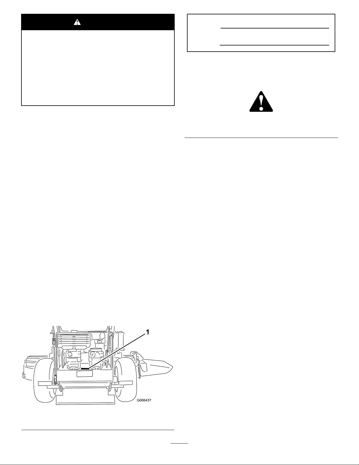
yourproductready.Figure1identiesthelocationofthe
modelandserialnumbersontheproduct.Writethenumbers
inthespaceprovided.
Figure2
1.Safetyalertsymbol
Thismanualuses2wordstohighlightinformation.
Importantcallsattentiontospecialmechanicalinformation
andNoteemphasizesgeneralinformationworthyofspecial
attention.
1.Locationofthemodelandserialnumbers
©2014—TheToro®Company
8111LyndaleAvenueSouth
Bloomington,MN55420
Figure1
Contactusatwww.Toro.com.
2
PrintedintheUSA
AllRightsReserved
Page 3

Contents
Safety...........................................................................4
GeneralLawnMowerSafety.....................................4
SoundPressure.......................................................5
SoundPower..........................................................5
VibrationLevel.......................................................5
SlopeIndicator.......................................................6
SafetyandInstructionalDecals.................................7
ProductOverview.........................................................10
Controls...............................................................10
Specications........................................................11
Operation....................................................................11
AddingFuel...........................................................11
CheckingtheEngine-OilLevel.................................12
PuttingSafetyFirst.................................................12
OperatingtheParkingBrake....................................12
StartingandStoppingtheEngine..............................13
OperatingtheMowerBladeControl(PTO)................14
TheSafety-InterlockSystem....................................14
DrivingForwardorBackward..................................15
StoppingtheMachine.............................................15
PushingtheMachinebyHand..................................16
TransportingMachines............................................16
SideDischargingorMulchingtheGrass.....................16
AdjustingtheHeight-of-Cut....................................17
AdjustingtheAnti-ScalpRollers...............................17
AdjustingtheFlowBafe........................................17
PositioningtheFlowBafe......................................18
Maintenance.................................................................19
RecommendedMaintenanceSchedule(s)......................19
Lubrication...............................................................20
LubricatingtheMachine..........................................20
LubricatingtheBearings..........................................20
GreasingthePTODriveBeltIdler............................20
EngineMaintenance..................................................21
ServicingtheAirCleaner.........................................21
ServicingtheEngineOil..........................................21
ServicingtheSparkPlugs.........................................23
FuelSystemMaintenance...........................................24
DrainingtheFuelTank...........................................24
ReplacingtheFuelFilter..........................................25
ElectricalSystemMaintenance....................................25
ServicingtheFuses.................................................25
DriveSystemMaintenance.........................................26
AdjustingtheTracking...........................................26
CheckingtheTirePressure......................................26
ReplacingtheCasterWheelForkBushings.................26
ServicingtheCasterWheelandBearings....................27
AdjustingtheElectricClutch....................................28
CoolingSystemMaintenance......................................28
CleaningtheAirIntakeScreen..................................28
BrakeMaintenance....................................................29
ServicingtheBrakes................................................29
BeltMaintenance......................................................30
InspectingtheBelts................................................30
ReplacingtheMowerBelt........................................30
ReplacingthePTO-DriveBelt..................................30
AdjustingthePTO-Drive-Belt-Idler-Spring
Anchor..............................................................31
ReplacingthePump-DriveBelt................................31
ControlsSystemMaintenance.....................................32
AdjustingtheMotion-Control-Handle
Positions............................................................32
HydraulicSystemMaintenance....................................34
ServicingtheHydraulicSystem.................................34
MowerDeckMaintenance...........................................37
ServicingtheCuttingBlades.....................................37
CorrectingtheMowerQualityofCut........................38
SettinguptheFrame...............................................38
CheckingtheMowerDeckFront-to-Rear
Pitch.................................................................40
ChangingtheMowerDeckFront-to-Rear
Pitch.................................................................40
CheckingtheMowerDeckSide-to-Side
Height...............................................................41
ChangingtheMowerDeckSide-to-Side
Height...............................................................41
MatchingtheHeight-of-Cut.....................................41
ReplacingtheGrassDeector..................................42
Cleaning...................................................................42
CleaningundertheMower.......................................42
DisposingofWaste.................................................42
Storage........................................................................43
CleaningandStorage..............................................43
Troubleshooting...........................................................44
3
Page 4

Safety
ThismachinehasbeendesignedinaccordancewithENISO
5395:2013.
Improperlyusingormaintainingthemachinecanresult
ininjury.Toreducethepotentialforinjury,complywith
thesesafetyinstructionsandalwayspayattentiontothe
safetyalertsymbol,whichmeans
Danger
withtheinstructionmayresultinpersonalinjuryor
death.
—personalsafetyinstruction.Failuretocomply
GeneralLawnMowerSafety
Thiscuttingmachineiscapableofamputatinghandsandfeet
andthrowingobjects.Failuretoobservethefollowingsafety
instructionscouldresultinseriousinjuryordeath.
Training
•Readtheinstructionscarefully.Befamiliarwiththe
controlsandtheproperuseoftheequipment.
•Neverallowchildrenorpeopleunfamiliarwiththese
instructionstousethemower.Localregulationscan
restricttheageoftheoperator.
•Keepinmindthattheoperatororuserisresponsiblefor
accidentsorhazardsoccurringtootherpeopleortheir
property.
•Understandexplanationsforallpictogramsusedonthe
mowerorintheinstructions.
Gasoline
WARNING-Gasolineishighlyammable.Takethe
followingprecautions.
•Storefuelincontainersspecicallydesignedforthis
purpose.
•Refueloutdoorsonlyanddonotsmokewhilerefueling.
•Addfuelbeforestartingtheengine.Neverremovethe
capofthefueltankoradgasolinewhiletheengineis
runningorwhentheengineishot.
•Ifgasolineisspilled,donotattempttostarttheengine
butmovethemowerawayfromtheareaofspillageand
avoidcreatinganysourceofignitionuntilgasolinevapors
havedissipated.
•Replaceallfueltankandcontainercapssecurely.
Preparation
•Whilemowing,alwayswearsubstantialfootwearandlong
trousers.Donotoperatetheequipmentwhenbarefoot
orwearingopensandals.
•Thoroughlyinspecttheareawheretheequipmentisto
beusedandremoveallstones,sticks,wires,bonesand
otherforeignobjects.
Caution, W ar ning ,
•Beforeusing,alwaysvisuallyinspecttoseethatguards,
andsafetydevices,suchasdeectorsand/orgrass
catchers,areinplaceandworkingcorrectly.
•Beforeusing,alwaysvisuallyinspecttoseethattheblades,
bladeboltsandcutterassemblyarenotwornordamaged.
Replacewornordamagedbladesandboltsinsetsto
preservebalance.
or
Starting
•Disengageallbladeanddriveclutchesandshiftinto
neutralbeforestartingtheengine.
•Donottiltmowerwhenstartingtheengineorswitching
onthemotor,unlessthemowerhastobetiltedfor
starting.Inthiscase,donottiltitmorethanabsolutely
necessaryandliftonlythepart,whichisawayfromthe
operator.
•Starttheengineorswitchonthemotorcarefully
accordingtoinstructionsandwithfeetwellawayfrom
theblade(s)andnotinfrontofthedischargechute.
Operation
•Nevermowwhilepeople,especiallychildren,orpetsare
nearby.
•Mowonlyindaylightoringoodarticiallight.
•Avoidoperatingthelawnmowerinwetgrass,where
feasible.
•Stayalertforholesintheterrainandotherhiddenhazards.
•Neverdirectdischargeofmaterialtowardsbystanders.
•Donotputhandsorfeetnearorunderrotatingparts.
Keepclearofthedischargeopeningatalltimes.
•Neverpickuporcarryalawnmowerwhiletheengineis
running.
•Useextremecautionwhenreversingorpullinga
pedestriancontrolledlawnmowertowardsyou.
•Walk,neverrun.
•Slopes:
–Donotmowexcessivelysteepslopes.
–Exerciseextremecautionwhenonslopes.
–Mowacrossthefaceofslopes,neverupanddown
andexerciseextremecautionwhenchangingdirection
onslopes.
–Alwaysbesureofyourfootingonslopes.
•Uselowthrottlesettingswhenengagingthe
traction-clutch,especiallyinhighgears.Reducespeed
onslopesandinsharpturnstopreventoverturningor
lossofcontrol.
•Stopthebladeifthelawnmowerhastobetiltedfor
transportationwhencrossingsurfacesotherthangrass
andwhentransportingthelawnmowertoandfromthe
areatobemowed.
4
Page 5

•Donotoperatetheengineinaconnedspacewhere
dangerouscarbonmonoxidefumescancollect.
•Stoptheengine
–wheneveryouleavethelawnmower.
–beforerefueling.
–beforeremovingthegrasscatcher.
–beforemakingheightadjustmentunlessadjustment
canbemadefromtheoperator'sposition.
•Stoptheengineanddisconnectthespark-plugwireor
turnoffandremovethekey .
–beforeclearingblockagesoruncloggingchute.
–beforechecking,cleaningorworkingonthelawn
mower.
–afterstrikingaforeignobject,inspectthelawnmower
fordamageandmakerepairsbeforerestartingand
operatingthelawnmower.
–iflawnmowerstartstovibrateabnormally(check
immediately).
•Usecarewhenusingsulkies,and
–useonlyapproveddrawbarhitchpoints.
•Replacefaultysilencers.
•Ifthefueltankhastobedrained,dothisout-doors.
•Donotchangetheenginegovernorsettingsoroverspeed
theengine.Operatinganengineatexcessivespeedcan
increasethehazardofpersonalinjury.
•Onmultibladedlawnmowers,takecareasrotatingone
blademaycauseotherstorotate.
•Becarefulduringadjustmentofthelawnmowerto
prevententrapmentofthengersbetweenmovingblades
andxedpartsofthelawnmower.
•Toensurethebestperformanceandsafety,
purchaseonlygenuineTororeplacementpartsand
accessories.Donotuse
theymaycauseasafetyhazard.
will t
partsandaccessories;
SoundPressure
Thisunithasasoundpressurelevelattheoperator’searof88
dBA,whichincludesanUncertaintyValue(K)of1dBA.
Thesoundpressurelevelwasdeterminedaccordingtothe
proceduresoutlinedinENISO5395:2013.
–limitloadstothoseyoucansafelycontrol.
–donotturnsharply:usecarewhenreversing.
–donotcarrypassengers.
•Watchoutfortrafcwhencrossingornearroadways.
•Beforeleavingtheoperator'sposition
–disengagethepowertake-offandlowerthe
attachments.
–changeintoneutralandsettheparkingbrake.
–stoptheengineandremovethekey.
MaintenanceandStorage
•Keepallnuts,boltsandscrewstighttobesurethe
equipmentisinsafeworkingcondition.
•Donotusepressurecleaningequipmentonmachine.
•Neverstoretheequipmentwithgasolineinthetankand
insideabuildingwherefumescanreachanopename
orspark.
•Allowtheenginetocoolbeforestoringinanyenclosure.
SoundPower
Thisunithasaguaranteedsoundpowerlevelof100dBA,
whichincludesanUncertaintyValue(K)of1dBA.
Thesoundpowerlevelwasdeterminedaccordingtothe
proceduresoutlinedinISO11094.
VibrationLevel
Hand-Arm
Measuredvibrationlevelforrighthand=2.8m/s
Measuredvibrationlevelforlefthand=2.1m/s
UncertaintyValue(K)=1.4m/s
Measuredvaluesweredeterminedaccordingtotheprocedures
outlinedinENISO5395:2013.
2
2
2
•Toreducetherehazard,keeptheengine,silencer,
batterycompartmentandgasolinestoragearefreeof
grass,leaves,orexcessivegrease.
•Checkgrasscatchercomponentsandthedischargeguard
frequentlyandreplacewithmanufacturer'srecommended
parts,whennecessary.
•Replacewornordamagedpartsforsafety.
5
Page 6
SlopeIndicator
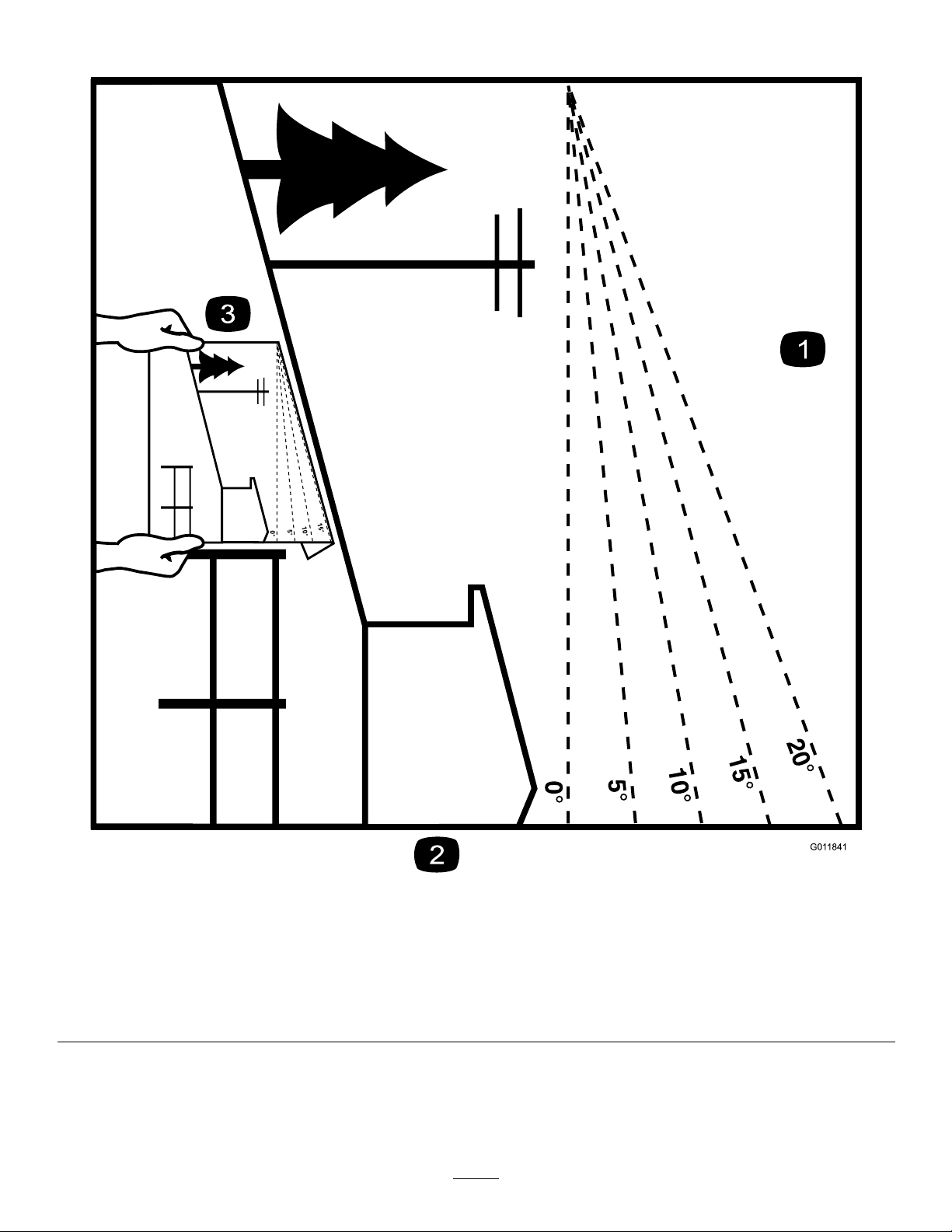
G011841
Figure3
Thispagemaybecopiedforpersonaluse.
1.Themaximumslopeyoucansafelyoperatethemachineonis20degrees.Usetheslopecharttodeterminethedegreeofslope
ofhillsbeforeoperating.Donotoperatethismachineonaslopegreaterthan20degrees.Foldalongtheappropriateline
tomatchtherecommendedslope.
2.Alignthisedgewithaverticalsurface,atree,building,fencepole,etc.
3.Exampleofhowtocompareslopewithfoldededge.
6
Page 7
SafetyandInstructionalDecals
Safetydecalsandinstructionsareeasilyvisibletotheoperatorandarelocatednearanyareaofpotential
danger.Replaceanydecalthatisdamagedorlost.
Manufacturer'sMark
1.Indicatesthebladeisidentiedasapartfromtheoriginal
machinemanufacturer.
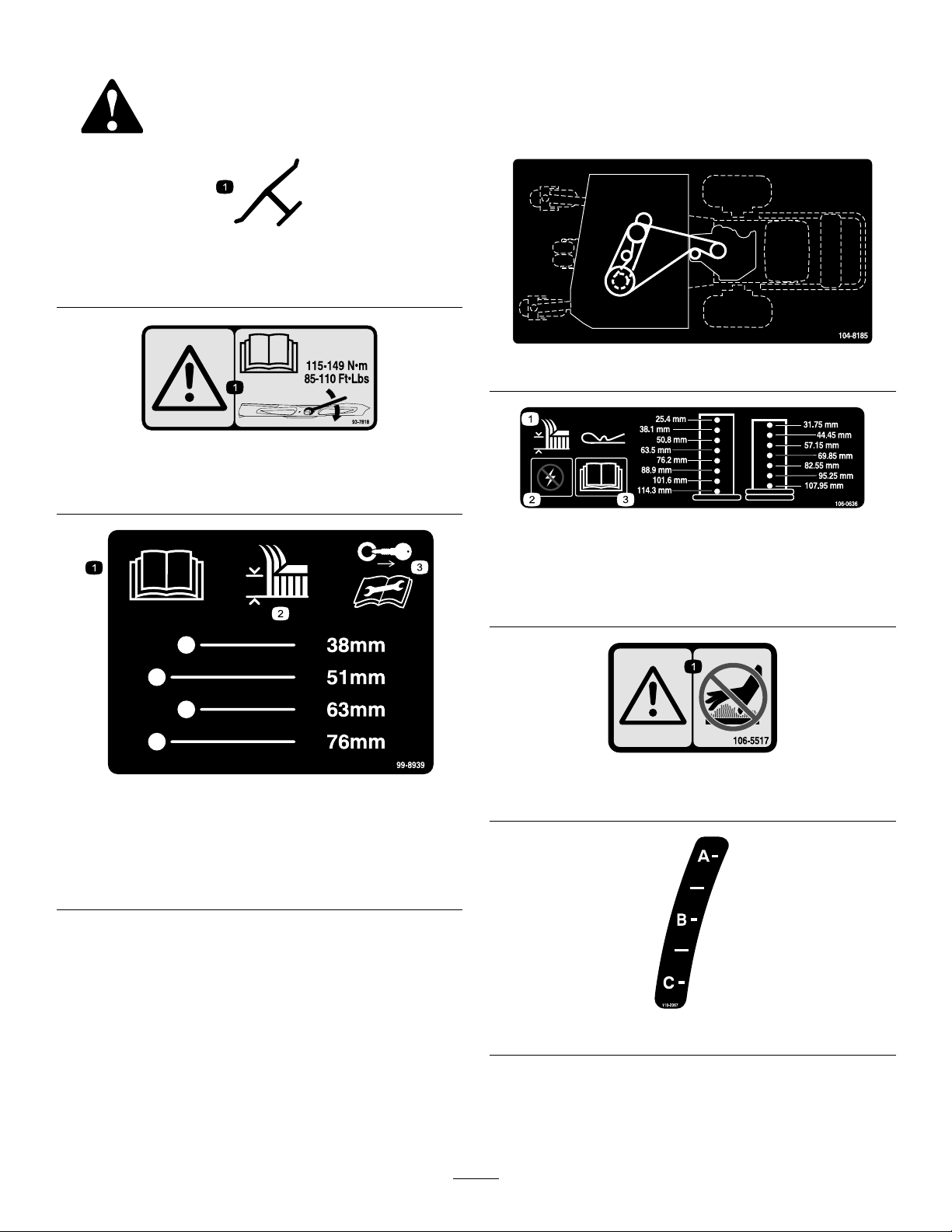
93-7818
1.Warning—readtheOperator'sManualforinstructionson
torquingthebladebolt/nutto115-149N-m(85-110ft-lb).
104-8185
1.ReadtheOperator's
Manual.
2.Heightofcut
99-8939
3.Removetheignitionkey
andreadtheinstructions
beforeservicingor
performingmaintenance.
106-0636
1.Height-of-cut3.ReadtheOperator's
Manualformore
information.
2.Warning—power
106-5517
1.Warning–DoNottouchthehotsurface.
110-2067
7
Page 8
112-8721
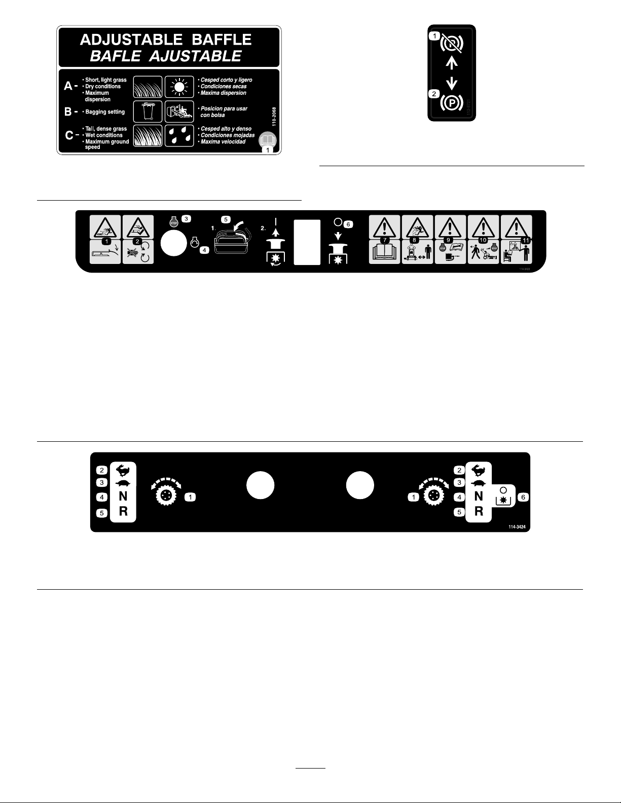
110-2068
1.ReadtheOperator'sManual.
1.Thrownobject
hazard—keepdeector
inplace.
2.Cutting,dismemberment
hazardofhandor
foot—stayawayfrom
movingparts.
3.Engine—stop
1.Parkingbrake—off
114-3422
4.Engine—start7.Warning—readthe
5.Movethemotioncontrol
levertotheneutralposition,
thenpulloutonPTO(Power
TakeOff)switchtoengage
theblades.
6.PushinonthePTO(Power
TakeOff)todisengagethe
blades.
Operator'sManual.
8.Thrownobject
hazard—keepbystanders
asafedistancefromthe
machine.
9.Warning—stoptheengine
andremovethesparkplug
wirebeforeperforming
anymaintenanceonthe
machine.
2.Parkingbrake—on
10.Warning—stoptheengine
beforeleavingthemachine.
11.Warning—donotoperate
thismachineunlessyou
aretrained.
1.Tractioncontrol
2.Fast4.Neutral
114-3424
3.Slow
5.Reverse
6.DisengagethePTO(PowerTake-off)
8
Page 9
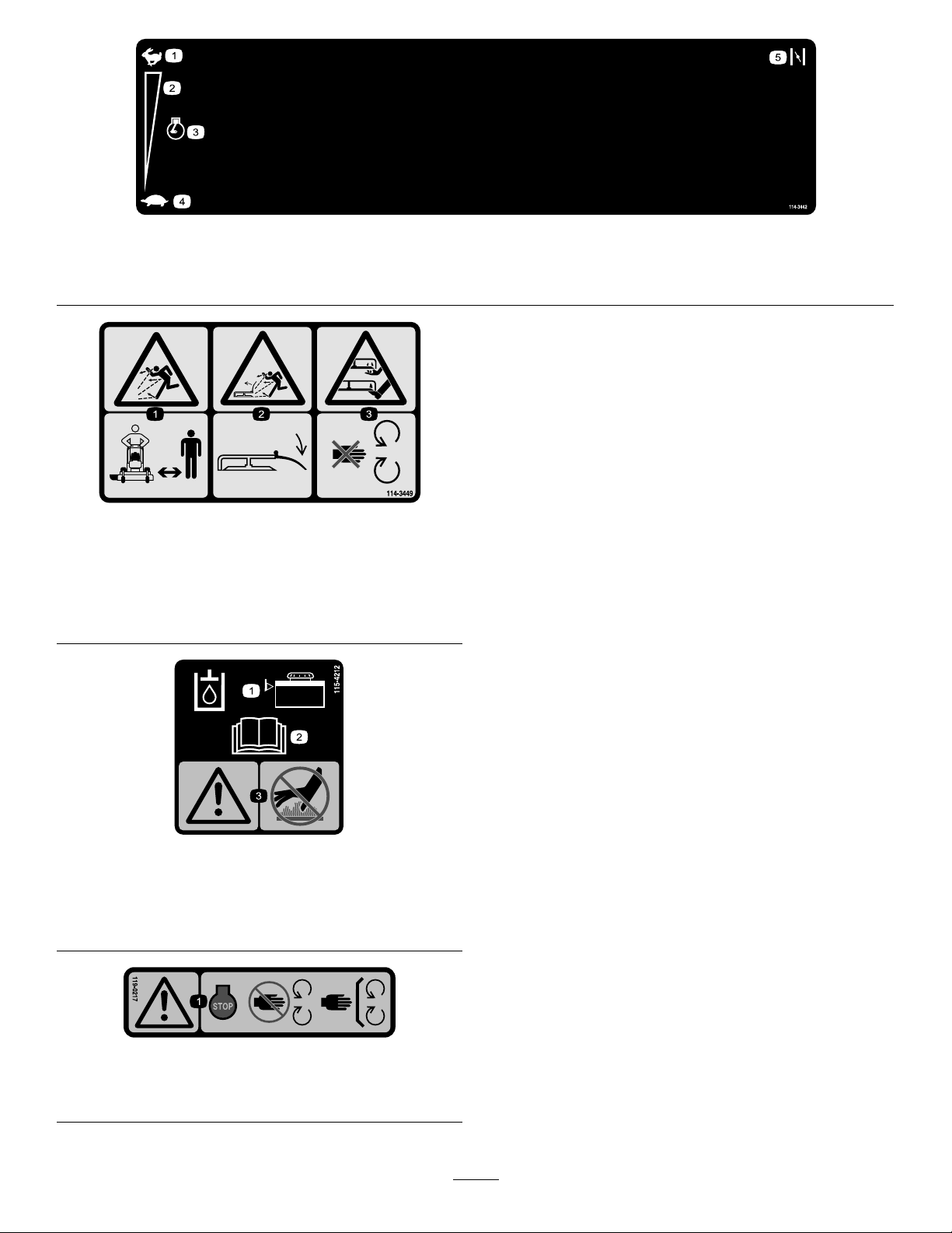
114-3442
1.Fast3.Engine
2.Continuousvariablesetting4.Slow
114-3449
1.Thrownobjecthazard—keepbystandersasafedistance
fromthemachine.
2.Thrownobjecthazard,mower—keepthedeectorinplace.
3.Cutting/dismembermentofhandorfoot—stayawayfrom
movingparts.
5.Choke
115-4212
1.Hydraulicoillevel3.Warning—donottouchthe
hotsurface.
2.ReadtheOperator's
Manual.
119-0217
1.Warning—stoptheengine;stayawayfrommovingparts;
keepallguardsandshieldsinplace.
9
Page 10
ProductOverview
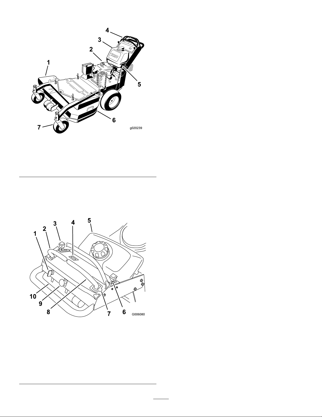
g020239
Figure4
1.Side-dischargechute
2.Engine6.Mowerdeck
3.Gastank
4.Controls
5.Parkingbrake
7.Frontcasterwheel
ThrottleControl
Thethrottlecontrolhas2positions:FastandSlow.
Choke
Usethechoketostartacoldengine.
Blade-ControlSwitch(PTO)
Theblade-controlswitch(PTO)isusedtoengagetheelectric
clutchtodrivethemowerbladeswiththerightmotion-control
leverinthecenter,unlockedposition.Pulltheswitchupto
engagethebladesandrelease.Todisengagetheblades,push
theblade-controlswitch(PTO)downormoveorreleasethe
rightmotion-controlleverintotheNeutral-Lockposition.
IgnitionSwitch
Thisswitchisusedtostartthemowerengineandhas3
positions:Start,Run,andOff.
Motion-ControlLevers
Themotion-controlleversareusedtodrivethemachine
forward,reverse,andturneitherdirection.
Controls
Becomefamiliarwithallthecontrols(Figure5)beforeyou
starttheengineandoperatethemachine.
Figure5
1.Ignitionswitch
2.Leftmotion-controllever7.Neutral-Lockpositionfor
3.Throttlecontrol8.Rightmotion-controllever
4.Hourmeter9.Blade-controlswitch
5.Fueltank
6.Choke
therightmotion-control
lever
(PTO)
10.Operator-manualtube
Neutral-LockPosition
TheNeutral-Lockpositionisusedwiththesafetyinterlock
systemtoengageanddisengagethemowerbladesandto
determinetheNeutralposition.
FuelShut-offValve
Closethefuelshut-offvalve(underthefueltank)when
transportingorstoringthemower.
HourMeter
Showsthetotalhoursthemachinehasbeenoperated.This
operatesonlywhenthemowerbladesareoperating.
Thehourmeterwillash3hoursbeforeandafteraservice
interval.Theserviceintervalsaresetfortherst8hours,
every100hoursthereafter,andevery400hours.
Note:Makesuremaintenanceisdoneatallrecommended
intervalsshownintheRecommendedMaintenanceSchedule.
10
Page 11

Attachments/Accessories
AselectionofToroapprovedattachmentsandaccessoriesis
availableforusewiththemachinetoenhanceandexpand
itscapabilities.ContactyourAuthorizedServiceDealeror
Distributororgotowww .Toro.comforalistofallapproved
attachmentsandaccessories.
Operation
AddingFuel
•Forbestresults,useonlyclean,fresh,unleadedgasoline
withanoctaneratingof87orhigher((R+M)/2rating
method).
Specications
Note:Specicationsanddesignaresubjecttochange
withoutnotice.
Widthwithdeectordown130cm(51-1/8inches)
Length
Height
Weight
199cm(78-1/2inches)
117cm(46inches)
303kg(667lb)
•Oxygenatedfuelwithupto10%ethanolor15%MTBE
byvolumeisacceptable.
•Ethanol:Gasolinewithupto10%ethanol(gasohol)
or15%MTBE(methyltertiarybutylether)byvolume
isacceptable.EthanolandMTBEarenotthesame.
Gasolinewith15%ethanol(E15)byvolumeisnot
approvedforuse.Neverusegasolinethatcontains
morethan10%ethanolbyvolume,suchasE15
(contains15%ethanol),E20(contains20%ethanol),or
E85(containsupto85%ethanol).Usingunapproved
gasolinemaycauseperformanceproblemsand/orengine
damagewhichmaynotbecoveredunderwarranty.
•Donotuseethanolblendsofgasoline(suchasE15
orE85)withmorethan10%ethanolbyvolume.
Performanceproblemsand/orenginedamagemayresult
whichmaynotbecoveredunderwarranty.
•Donotusegasolinecontainingmethanol.
•Donotstorefueleitherinthefueltankorfuelcontainers
overthewinterunlessafuelstabilizerisused.
•Donotaddoiltogasoline.
DANGER
Incertainconditions,gasolineisextremely
ammableandhighlyexplosive.Areorexplosion
fromgasolinecanburnyouandothersandcan
damageproperty.
•Fillthefueltankoutdoors,inanopenarea,
whentheengineiscold.Wipeupanygasoline
thatspills.
•Neverllthefueltankinsideanenclosedtrailer.
•Donotllthefueltankcompletelyfull.Add
gasolinetothefueltankuntilthelevelis6to13
mm(1/4to1/2inch)belowthebottomofthe
llerneck.Thisemptyspaceinthetankallows
gasolinetoexpand.
•Neversmokewhenhandlinggasoline,andstay
awayfromanopenameorwheregasoline
fumesmaybeignitedbyaspark.
•Storegasolineinanapprovedcontainerand
keepitoutofthereachofchildren.Neverbuy
morethana30-daysupplyofgasoline.
•Donotoperatewithoutentireexhaustsystemin
placeandinproperworkingcondition.
11
Page 12

DANGER
Incertainconditionsduringfueling,static
electricitycanbereleasedcausingasparkwhich
canignitethegasolinevapors.Areorexplosion
fromgasolinecanburnyouandothersandcan
damageproperty.
•Alwaysplacegasolinecontainersontheground
awayfromyourvehiclebeforelling.
•Donotllgasolinecontainersinsideavehicleor
onatruckortrailerbedbecauseinteriorcarpets
orplastictruckbedlinersmayinsulatethe
containerandslowthelossofanystaticcharge.
•Whenpractical,removegas-poweredequipment
fromthetruckortrailerandrefueltheequipment
withitswheelsontheground.
•Ifthisisnotpossible,thenrefuelsuch
equipmentonatruckortrailerfromaportable
container,ratherthanfromagasolinedispenser
nozzle.
•Ifagasolinedispensernozzlemustbeused,
keepthenozzleincontactwiththerimofthe
fueltankorcontaineropeningatalltimesuntil
fuelingiscomplete.
FillingtheFuelTank
1.Shuttheengineoffandsettheparkingbrake.
2.Cleanaroundeachfueltankcapandremovethecap.
3.Addunleadedregulargasolinetobothfueltanks,until
thelevelis6to13mm(1/4to1/2inch)belowthe
bottomofthellerneck.
Thisspaceinthetankallowsgasolinetoexpand.Do
notllthefueltankscompletelyfull.
4.Installfueltankcapssecurely .
5.Wipeupanygasolinethatmayhavespilled.
CheckingtheEngine-OilLevel
Beforeyoustarttheengineandusethemachine,checktheoil
levelintheenginecrankcase;refertoCheckingOilLevelin
EngineMaintenance(page21).
Note:Determinetheleftandrightsidesofthemachine
fromthenormaloperatingposition.
PuttingSafetyFirst
Carefullyreadallthesafetyinstructionsanddecalsinthe
safetysection.Knowingthisinformationcouldhelpyouor
anybystandersavoidinjury.
WARNING
Gasolineisharmfulorfatalifswallowed.Long-term
exposuretovaporscancauseseriousinjuryand
illness.
•Avoidprolongedbreathingofvapors.
•Keepfaceawayfromnozzleandgastankor
conditioneropening.
•Keepgasawayfromeyesandskin.
UsingStabilizer/Conditioner
Useafuelstabilizer/conditionerinthemachinetoprovide
thefollowingbenets:
•Keepsgasolinefreshduringstorageof90daysorless.
Forlongerstorageitisrecommendedthatthefueltank
bedrained.
•Cleanstheenginewhileitruns
•Eliminatesgum-likevarnishbuildupinthefuelsystem,
whichcauseshardstarting
Important:Donotusefueladditivescontaining
methanolorethanol.
Addthecorrectamountofgasstabilizer/conditionertothe
gas.
Note:Afuelstabilizer/conditionerismosteffectivewhen
mixedwithfreshgasoline.Tominimizethechanceofvarnish
depositsinthefuelsystem,usefuelstabilizeratalltimes.
Theuseofprotectiveequipmentforeyes,hearing,feet,and
headisrecommended.
CAUTION
Thismachineproducessoundlevelsinexcessof
85dBAattheoperator'searandcancausehearing
lossthroughextendedperiodsofexposure.
Wearhearingprotectionwhenoperatingthis
machine.
OperatingtheParkingBrake
Alwayssettheparkingbrakewhenyoustopthemachineor
leaveitunattended.Beforeeachuse,checktheparkingbrake
forproperoperation.
Iftheparkingbrakedoesnotholdsecurely,adjustit.Referto
ServicingtheBrakes(page29).
CAUTION
Childrenorbystandersmaybeinjuredifthey
moveorattempttooperatethemachinewhileitis
unattended.
Alwaysremovetheignitionkeyandsettheparking
brakewhenleavingthemachineunattended,even
ifjustforafewminutes.
12
Page 13
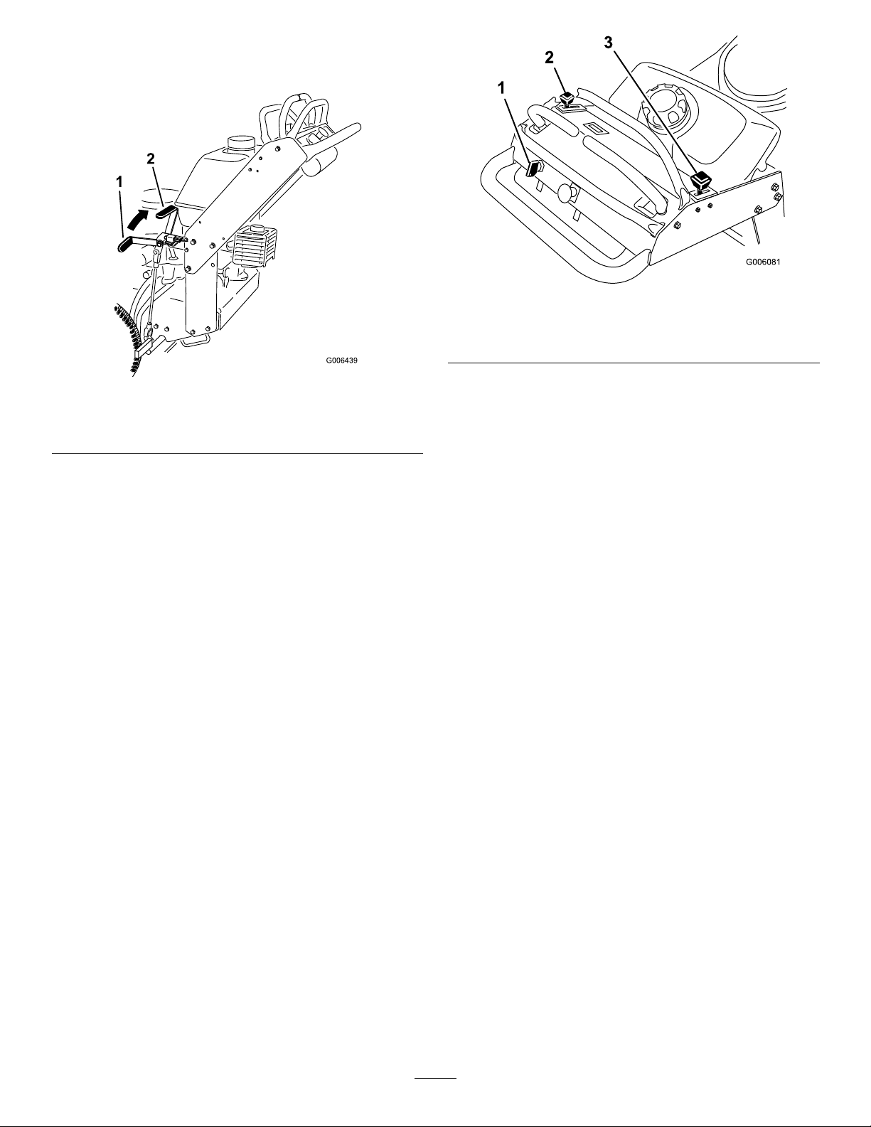
SettingtheParkingBrake
Pulltheparkingbrakeleverrearward(Figure6).
Figure7
Figure6
1.Parkingbrakelever(inthe
releasedposition)
2.Parkingbrakelever(inthe
engagedposition)
ReleasingtheParkingBrake
Pushtheparkingbrakeleverforward.
StartingandStoppingthe Engine
StartingtheEngine
1.Connectthewirestothesparkplugs.
2.Openthefuelvalve.
3.Settheparkingbrake.
4.Movethethrottlecontroltofastandmovethechoke
levertotheonpositionbeforestartingacoldengine
(Figure7).
Note:Awarmorhotenginemaynotrequirechoking.
Tostartawarmengine,movethrottlecontrolmidway
betweentheFastandSlowpositions.
1.Ignitionswitch
2.Throttlelever
5.Turntheignitionkeytothestartpositiontoenergize
thestarter.Whentheenginestarts,releasethekey.
Note:Donotengagethestarterformorethan5
secondsatatime.Iftheenginefailstostart,allow
fora15secondcool-downperiodbetweenattempts.
Failuretofollowtheseinstructionscanburnoutthe
startermotor.
6.Whenenginestarts,movethethrottlecontrolbetween
thefastandslowpositionandmovethechokeleverto
theoffposition.Allowtheenginetowarmupandthen
movethethrottlecontroltothefastposition.
3.Choke
StoppingtheEngine
1.Movethemotion-controlleverstotheNeutralposition
andmovetherightmotion-controlleverintothe
Neutral-Lockposition.
2.Movethethrottlelevertoslow(Figure7).
3.Iftheenginehasbeenworkinghardorishot,letthe
engineidlefor30to60secondsbeforeturningthe
engineoff.
4.Tostoptheengine,turntheignitionkeytooff.
Important:Makesurefuelshutoffvalveisclosed
beforetransportingorstoringthemachine,asfuel
leakagemayoccur.Beforestoringthemachine,
pullwireoffsparkplug(s)topreventpossibilityof
accidentalstarting.
13
Page 14
OperatingtheMowerBlade
TheSafety-InterlockSystem
Control(PTO)
Theblade-controlswitch(PTO)isusedinconjunctionwith
therightmotion-controllevertoengageanddisengagethe
mowerblades.
EngagingtheMowerBlades(PTO)
1.Toengagethemowerblades,movetheright
motion-controllevertothecenter,unlockedposition
(Figure8).
2.Pulltheblade-controlswitch(PTO)upandreleaseit
whileholdingdowntherightmotion-controlleverin
thecenter,unlockedposition.
CAUTION
Ifthesafety-interlockswitchesaredisconnectedor
damaged,themachinecouldoperateunexpectedly,
causingpersonalinjury.
•Donottamperwiththeinterlockswitches.
•Checktheoperationoftheinterlockswitches
dailyandreplaceanydamagedswitchesbefore
operatingthemachine.
UnderstandingtheSafety-Interlock
System
Thesafety-interlocksystemisdesignedtopreventthemower
bladesfromrotatingunless:
•Therightmotion-controlleverismovedtothecenter,
unlockedposition.
•Theblade-controlswitch(PTO)ispulledtotheOn
position.
Thesafety-interlocksystemisdesignedtostopthemower
bladesifyoumoveorreleasetherightmotion-control
leverintotheNeutral-Lockposition.
Figure8
1.Blade-controlswitch
(PTO)
2.Rightmotion-controllever
pusheddownintothe
center,unlockedposition
3.Rightmotion-controllever
inNeutral-Lockposition
4.Leftmotion-controllever
DisengagingtheMowerBlades(PTO)
Thefollowingare2optionsfordisengagingthemowerblades.
•Pushtheblade-controlswitch(PTO)downtotheOff
position.
•Movethemotion-controlleverstotheNeutralposition
andmovetherightmotion-controlleverintothe
Neutral-Lockposition.
TestingtheSafety-InterlockSystem
ServiceInterval:Beforeeachuseordaily
Note:Ifthesafetysystemdoesnotoperateasdescribed
below,haveanAuthorizedServiceDealerrepairthesafety
systemimmediately.
1.Starttheengine;refertoStartingandStoppingthe
EngineinStartingandStoppingtheEngine(page13).
2.Settheparkingbrake.
3.Movetherightmotion-controllevertothecenter,
unlockedposition.
Note:Thebladesshouldnotrotate.
4.Movethemotion-controlleversforward.
Note:Theengineshouldkill.
5.Starttheengineandreleasetheparkingbrake.
6.Movetherightmotion-controllevertothecenter,
unlockedposition.
7.Continueholdingtherightmotion-controlleverin
thecenter,unlockedpositionandpulluponthe
blade-controlswitch(PTO)andrelease.
Note:Theclutchshouldengageandthemower
bladesbeginrotating.
8.Moveorreleasetherightmotion-controlleverintothe
Neutral-Lockposition.
Note:Thebladesshouldstoprotating.
9.Movetherightmotion-controllevertothecenter,
unlockedposition.
14
Page 15
10.Continueholdingtherightmotion-controlleverin
thecenter,unlockedpositionandpullupontheblade
controlswitch(PTO)andrelease.
Theclutchshouldengageandthemowerbladesbegin
rotating.
11.Pushtheblade-controlswitch(PTO)downtotheOff
position.
Note:Thebladesshouldstoprotating.
12.Withtheenginerunning,pulluptheblade-control
switch(PTO)andreleasewithoutholdingright
motion-controllevertothecenter,unlockedposition.
Note:Thebladesshouldnotrotate.
DrivingForwardorBackward
Thethrottlecontrolregulatestheenginespeedasmeasured
inrpm(revolutionsperminute).Placethethrottlecontrolin
thefastpositionforbestperformance.Alwaysoperateinthe
fullthrottlepositionwhenmowing.
CAUTION
Machinecanspinveryrapidly.Operatormaylose
controlofmachineandcausepersonalinjuryor
damagetomachine.
•Usecautionwhenmakingturns.
•Slowthemachinedownbeforemakingsharp
turns.
DrivingForward
1.Releasetheparkingbrake;refertoReleasingtheParking
BrakeinStartingandStoppingtheEngine(page13).
2.Movetherightmotion-controllevertothecenter,
un-lockedposition.
3.Togoforward,slowlypushthemotion-controllevers
forward(Figure9).
Note:Theenginewillkillifthetraction-controllevers
aremovedwiththeparkingbrakeengaged.
Togostraight,applyequalpressuretoboth
motion-controllevers(Figure9).
Toturn,movethemotion-controllevertowardthe
Neutralpositioninthedirectionyouwanttoturn
(Figure9).
Thefartheryoumovethetraction-controlleversin
eitherdirection,thefasterthemachinewillmovein
thatdirection.
Tostop,pullthemotion-controlleversbacktothe
Neutralposition.
Figure9
1.Forward2.Backward
DrivingBackward
1.Movetherightmotion-controllevertothecenter,
unlockedposition.
2.Togobackward,slowlypullthemotion-controllevers
rearward(Figure9).
Togostraight,applyequalpressuretoboth
motion-controllevers(Figure9).
Toturn,releasepressureonthemotion-controllever
towardthedirectionyouwanttoturn(Figure9).
Tostop,pushthemotion-controlleverstotheNeutral
position.
StoppingtheMachine
Tostopthemachine,movethemotion-controlleverstothe
Neutralposition,movetherightmotion-controlleverintothe
Neutral-Lockposition,disengagethepowertake-off(PTO),
andturntheignitionkeytotheOffposition.
Settheparkingbrakewhenyouleavethemachine;referto
SettingtheParkingBrakeinStartingandStoppingtheEngine
(page13).
Removethekeyfromtheignitionswitch.
CAUTION
Childrenorbystandersmaybeinjuredifthey
moveorattempttooperatethetractorwhileitis
unattended.
Alwaysremovetheignitionkeyandsettheparking
brakewhenleavingthemachineunattended,even
ifjustforafewminutes.
15
Page 16

PushingtheMachinebyHand
Theby-passvalvesallowthemachinetobepushedbyhand
withouttheenginerunning.
Important:Alwayspushthemachinebyhand.Never
towthemachinebecausehydraulicdamagemayoccur.
1.DisengagethePTO ,movethemotion-controlleversto
theNeutral-Lockedpositionandsettheparkingbrake.
2.Opentheby-passvalveonbothpumpsbyturning
themcounterclockwise1to2turns.Thisallows
hydraulicuidtoby-passthepumpsandthewheels
toturn(Figure10).
Note:Rotatetheby-passvalvesamaximumof2turns
sothevalvedoesnotcomeoutofthebodycausing
uidtorunout.
3.Loadthemachineontothetrailerortruck.
4.Stoptheengine,removethekey,setthebrake,and
closethefuelvalve.
5.Usethemetaltiedownloopsonthemachineto
securelyfastenthemachinetothetrailerortruckwith
straps,chains,cable,orropes(Figure11).
6.Fastenthefrontofthemachinetothetrailerortruck
withstraps,chains,cable,orropes.
Figure11
1.Tiedownloop
Figure10
1.Pumpby-passvalve
3.Releasetheparkingbrake.
4.Pushthemachinetothedesiredlocation.
5.Settheparkingbrake.
6.Closetheby-passvalves,butdonotovertightenthem.
Important:Donotstartoroperatethemachine
withtheby-passvalvesopen.Damagetosystem
mayoccur.
TransportingMachines
Useaheavy-dutytrailerortrucktotransportthemachine.
Ensurethatthetrailerortruckhasallnecessarybrakes,
lighting,andmarkingasrequiredbylaw .Pleasecarefullyread
allthesafetyinstructions.Knowingthisinformationcould
helpyou,yourfamily,pets,orbystandersavoidinjury.
SideDischargingorMulching theGrass
Thismowerhasahingedgrassdeectorthatdisperses
clippingstothesideanddowntowardtheturf.
DANGER
Withoutthegrassdeector,dischargecover,or
completegrasscatcherassemblymountedin
place,youandothersareexposedtobladecontact
andthrowndebris.Contactwithrotatingmower
blade(s)andthrowndebriswillcauseinjuryor
death.
•Neverremovethegrassdeectorfromthemower
becausethegrassdeectorroutesmaterialdown
towardtheturf.Ifthegrassdeectorisever
damaged,replaceitimmediately .
•Neverputyourhandsorfeetunderthemower.
•Nevertrytocleardischargeareaormower
bladesunlessyoureleasethebailandthepower
takeoff(PTO)isoff.Rotatetheignitionkeyto
Off.Alsoremovethekeyandpullthewire(s)off
thesparkplug(s).
Totransportthemachine:
1.Ifusingatrailer,connectittothetowingvehicleand
connectthesafetychains.
2.Ifapplicable,connectthetrailerbrakes.
16
Page 17
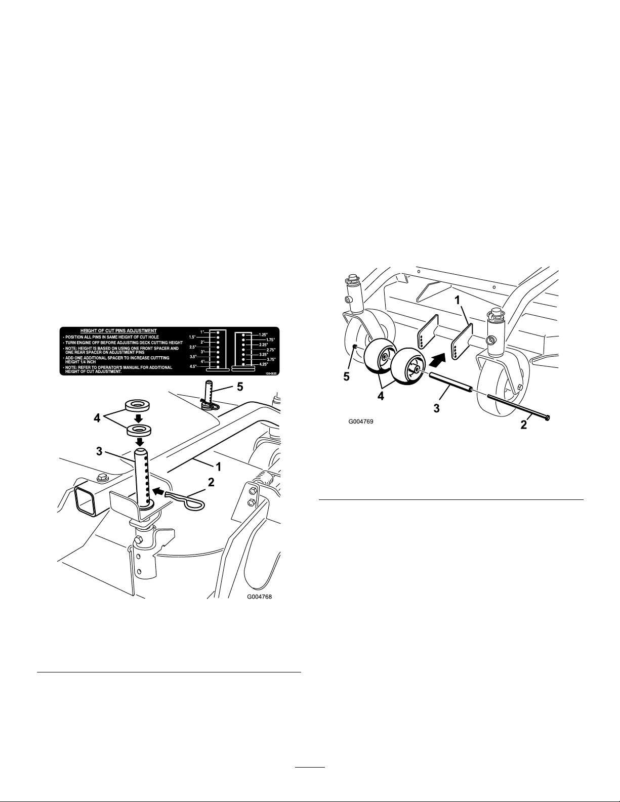
AdjustingtheHeight-of-Cut
AdjustingtheAnti-Scalp
Theheight-of-cutcanbeadjustedfrom25to114mm(1
to4-1/2inch)in6mm(1/4inch)increments.Adjustment
isdonebyrelocating4hairpincotterpinsindifferenthole
locationandbyaddingorremovingspacers.
Note:Allheight-of-cutpinsneedatleast1spacerordamage
canoccurtobushingifnoneareused.
Note:Allheight-of-cutpinscanuse2spacersmaximum.
1.Selectholeinheight-of-cutpostandnumberofspacers
correspondingtotheheight-of-cutdesired(Figure12).
2.Usingthelifthandle,raisesideofdeckandremove
hairpincotter(Figure12).
3.Addorremovespacersifneededandthenalignholes
andinserthairpincotter(Figure12).
Note:Spareheight-of-cutspacersmaybestoredon
postsandretainedbyahairpincotter.
Important:All4hairpincotterpinsmustbeinthe
sameholelocationandwiththecorrectnumberof
spacersforalevelcut.
Rollers
Theanti-scalprollersneedtobeadjustedintheproperhole
locationforeachheight-of-cutposition.Thereneedstobe10
mm(3/8inch)minimumclearanceabovetheground.
Note:Iftheanti-scalprollersareadjustedtoolowitcan
causeexcesswearoftherollers.
1.Afteradjustingheight-of-cut,checktheanti-scalp
rollerssothatthereisaminimumof10mm(3/8inch)
clearanceabovetheground(Figure13).
2.Ifadjustmentisneeded,removethebolt,washersand
nut(Figure13).
3.Selectaholepositionsotheanti-scalprollersarea
minimumof10mm(3/8inch)offtheground(Figure
13).
4.Installtheboltandnut(Figure13).
Figure12
1.Carrierframe4.Spacers
2.Hairpincotter
3.Backheight-of-cutpost
5.Frontheight-of-cutpost
Figure13
1.Mowerdeck4.Anti-scalprollers
2.Bolt5.Nut
3.Spacer
5.Incertainmowingconditionsandterrain,amismatch
ofcuttingheightmaybeseen.Adjustingtheoutside
anti-scalprollerstotheminimumsettingof10mm
(3/8inch)willhelppreventthemowerdeckcutting
toolowontheoutsideandminimizethemismatch.
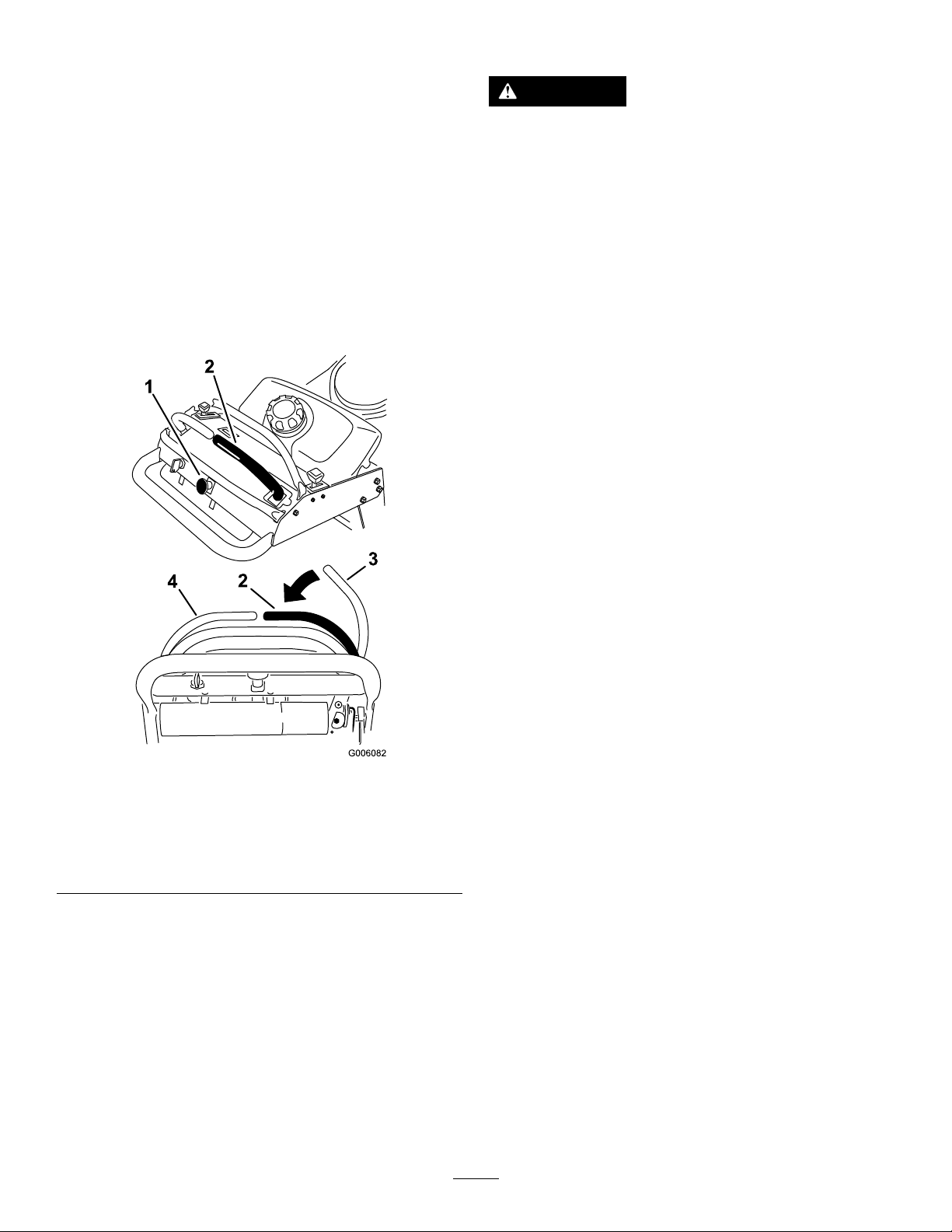
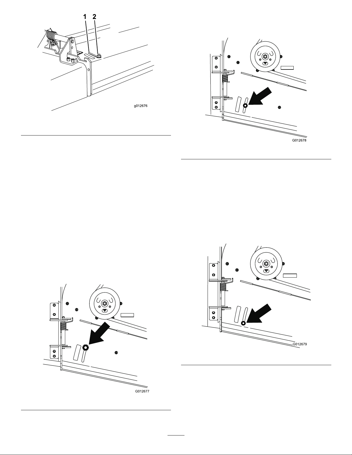
AdjustingtheFlowBafe
Themowerdischargeowcanbeadjustedfordifferenttypes
ofmowingconditions.Positionthecamlockandbafeto
givethebestqualityofcut.
1.DisengagethePTO ,movethemotion-controlleversto
theNeutral-Lockedpositionandsettheparkingbrake.
2.Stoptheengine,removethekey,andwaitforallmoving
partstostopbeforeleavingtheoperatingposition.
3.Toadjustthebafe,loosenthenut(Figure14).
4.Adjustthebafeandnutintheslottothedesired
dischargeowandtightenthenut.
17
Page 18
g012676
1 2
Figure14
G012677
G012678
G012679
PositionB
Usethispositionwhenbagging(Figure16).
1.Slot
2.Nut
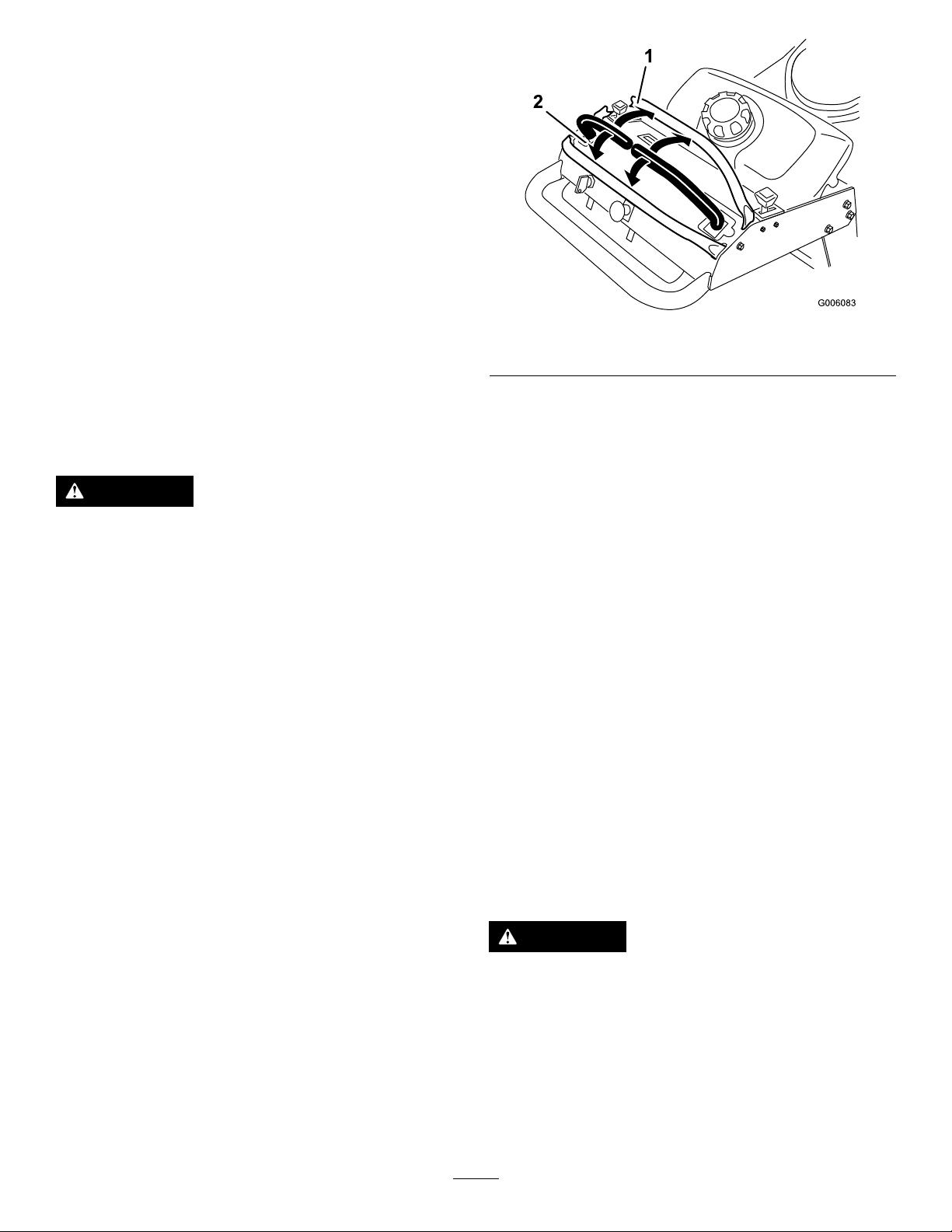
PositioningtheFlowBafe
Thefollowingguresareonlyrecommendationsforuse.
Adjustmentswillvarybygrasstype,moisturecontent,and
heightofgrass.
Note:Iftheenginepowerdrawsdownandthemower
groundspeedisthesame,openupthebafe.
PositionA
Thisisthefullrearposition(seeFigure15).Thesuggested
useforthispositionisafollows:
•Useforshort,lightgrassmowingconditions.
•Useindryconditions.
•Forsmallergrassclippings.
•Propelsgrassclippingsfartherawayfromthemower.
Figure16
PositionC
Thisisthefullopenposition.Thesuggesteduseforthis
positionisasfollows(Figure17):
•Useintall,densegrassmowingconditions.
•Useinwetconditions.
•Lowerstheenginepowerconsumption.
•Allowsincreasedgroundspeedinheavyconditions.
Figure15
Figure17
18
Page 19

Maintenance
Note:Determinetheleftandrightsidesofthemachinefromthenormaloperatingposition.
RecommendedMaintenanceSchedule(s)
MaintenanceService
Interval
Aftertherst8hours
Beforeeachuseordaily
Every25hours
Every50hours
Every100hours
Every200hours
MaintenanceProcedure
•Changetheengineoil.
•Checkthehydraulicuid.
•Changethehydrauliclter.
•Checkthesafety-interlocksystem.
•Greasethefrontcasterpivotbearing.
•Checktheengineoillevel.
•Cleantheairintakescreen.
•Checkthebrakes.
•Inspecttheblades.
•Cleanthemowerdeck.
•Cleanfoamaircleanerelement.
•Checkthehydraulicuid.
•GreasethePTObeltidler .
•Checkthepaperaircleanerelement.
•Checkthetirepressure.ormonthly,whicheveroccursrst.
•Inspectthebeltsforcracksandwear.
•Changetheengineoil.
•Checkthesparkplugs.
•Adjusttheelectricclutch.
•Checkthehydrauliclines.
•Replacethepaperaircleanerelement.
•Changetheoillter.
•Replacethefuellter.oryearly,whicheveroccursrst.
•Changethehydraulicuid.
•Changethehydrauliclter.
Every400hours
Beforestorage
•Greasethefrontwheelbearings(moreoftenindirtyordustyconditions).
•Paintchippedsurfaces.
•Performallmaintenanceprocedureslistedabovebeforestorage.
Important:Refertoyourengineowner'smanualforadditionalmaintenanceprocedures.
CAUTION
Ifyouleavethekeyintheignitionswitch,someonecouldaccidentlystarttheengineandseriouslyinjure
youorotherbystanders.
Removethekeyfromtheignitionanddisconnectthesparkplugwiresfromthesparkplugsbeforeyoudo
anymaintenance.Setthewiresasidesothattheydonotaccidentallycontactthesparkplugs.
19
Page 20
Lubrication
GreasingthePTODriveBelt
GreasewithNo.2general-purpose,lithium-basedor
molybdenum-basedgrease.
LubricatingtheMachine
1.DisengagethePTOandsettheparkingbrake.
2.Stoptheengine,removethekey,andwaitforallmoving
partstostopbeforeleavingtheoperatingposition.
3.Cleanthegreasettingswitharag.Makesuretoscrape
anypaintoffthefrontofthetting(s).
4.Connectagreaseguntothetting.Pumpgrease
intothettingsuntilgreasebeginstooozeoutofthe
bearings.
5.Wipeupanyexcessgrease.
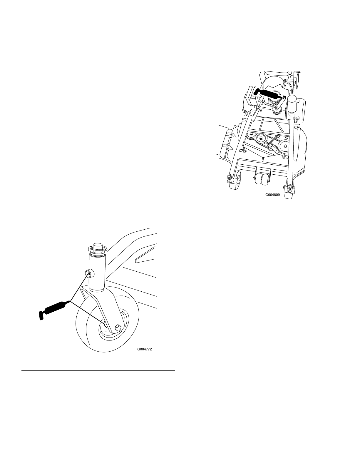
LubricatingtheBearings
ServiceInterval:Beforeeachuseordaily—Greasethefront
casterpivotbearing.
Every400hours—Greasethefrontwheelbearings
(moreoftenindirtyordustyconditions).
Lubricatethefrontcasterwheelbearingsandfrontpivots
(Figure18).
Idler
ServiceInterval:Every50hours—GreasethePTObelt
idler.
Greasetheidlerpulleypivot(Figure19).
Figure19
Figure18
20
Page 21
EngineMaintenance
ServicingtheAirCleaner
CleaningtheFoamAir-CleanerElement
1.Washthefoamelementinliquidsoapandwarmwater.
Whentheelementisclean,rinseitthoroughly .
2.Drytheelementbysqueezingitinacleancloth.
ServiceInterval/Specication
ServiceInterval:Every25hours
Every50hours
Every200hours/Yearly(whichevercomesrst)
Inspectthefoamandpaperelementsandreplacethemifthey
aredamagedorexcessivelydirty.
Note:Servicetheaircleanermorefrequently(everyfew
operatinghours)iftheoperatingconditionsareextremely
dustyorsandy .
Important:Donotoilthefoamorpaperelement.
RemovingtheFoamandPaper
Elements
1.DisengagethePTOandsettheparkingbrake.
2.Stoptheengine,removethekey,andwaitforallmoving
partstostopbeforeleavingtheoperatingposition.
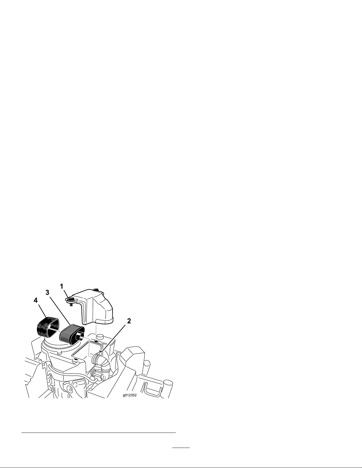
3.Cleanaroundtheaircleanertopreventdirtfrom
gettingintotheengineandcausingdamage(Figure20).
4.Unscrewthecoverknobsandremovetheaircleaner
cover(Figure20).
Important:Replacethefoamelementifitistorn
orworn.
ServicingthePaperAir-Cleaner
Element
1.Donotcleanthepaperlter.Replaceit(Figure20).
2.Inspecttheelementfortears,anoilylm,ordamageto
therubberseal.
3.Replacethepaperelementifitisdamaged.
InstallingtheFoamandPaperElements
Important:Topreventenginedamage,alwaysoperate
theenginewiththecompletefoamandpaperaircleaner
assemblyinstalled.
1.Carefullyslidethefoamelementontothepaperair
cleanerelement(Figure20).
2.Placetheaircleanerassemblyontotheaircleanerbase
andsecureitwiththe2wingnuts(Figure20).
3.Placetheaircleanercoverintopositionandtighten
thecoverknob(Figure20).
5.Unscrewthehoseclampandremovetheaircleaner
assembly(Figure20).
6.Carefullypullthefoamelementoffthepaperelement
(Figure20).
Figure20
1.Cover
2.Hoseclamp4.Foamelement
3.Paperelement
ServicingtheEngineOil
ServiceInterval:Beforeeachuseordaily
Aftertherst8hours
Every100hours
Every200hours—Changetheoillter.
Note:Changetheoilmorefrequentlywhentheoperating
conditionsareextremelydustyorsandy.
OilType:Detergentoil(APIserviceSF ,SG,SH,orSJ)
CrankcaseCapacity:1.7L(58oz)withthelterremoved;
1.5L(51oz)withoutthelterremoved
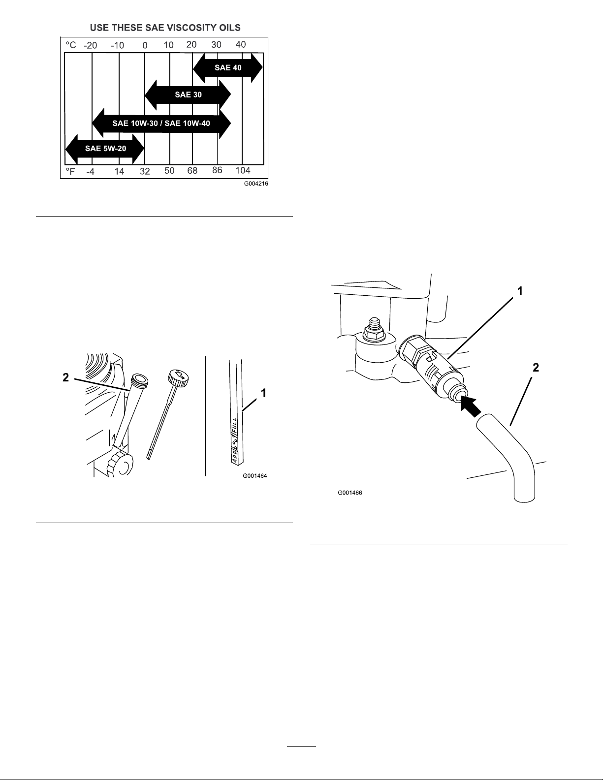
Viscosity:Refertothetable(Figure21).
21
Page 22
ChangingtheEngineOil
1.Starttheengineandletitrun5minutes.
Note:Thiswarmstheoilsoitdrainsbetter.
2.Parkthemachinesothatthedrainsideisslightlylower
thantheoppositesidetoensurethattheoildrains
completely.
3.DisengagethePTOandsettheparkingbrake.
4.Stoptheengine,removethekey,andwaitforallmoving
partstostopbeforeleavingtheoperatingposition.
5.Slidethedrainhoseovertheoil-drainvalve.
Figure21
CheckingtheEngine-OilLevel
1.Parkthemachineonalevelsurface.
2.DisengagethePTOandsettheparkingbrake.
3.Stoptheengine,removethekey,andwaitforallmoving
partstostopbeforeleavingtheoperatingposition.
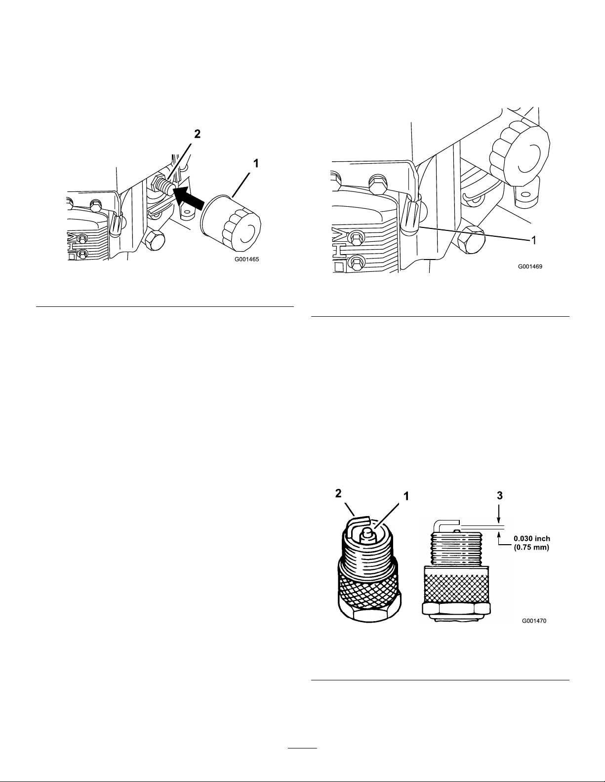
4.Cleanaroundtheoildipstick(Figure22)sothatdirt
cannotfallintothellerholeanddamagetheengine.
6.Placeapanbelowthedrainhose.Rotatetheoil-drain
valvetoallowoiltodrain(Figure23).
7.Whenoilhasdrainedcompletely,closethedrainvalve.
8.Removethedrainhose(Figure23).
Note:Disposeoftheusedoilatarecyclingcenter.
Figure22
1.Oildipstick
2.Fillertube
5.Unscrewtheoildipstickandwipetheendclean(Figure
22).
6.Slidetheoildipstickfullyintothellertube,butdonot
threadontotube(Figure22).
7.Pullthedipstickoutandlookattheend.Iftheoillevel
islow,slowlypouronlyenoughoilintothellertube
toraisetheleveltotheFullmark.
Important:Donotoverllthecrankcasewithoil
andruntheengine;enginedamagecanresult.
Figure23
1.Oil-drainvalve2.Oil-drainhose
9.Slowlypourapproximately80%ofthespeciedoil
intothellertube(Figure22).
10.Checktheoillevel;refertoCheckingtheEngine-Oil
Level(page12).
11.SlowlyaddtheadditionaloiltobringittotheFull
mark.
22
Page 23
ChangingtheOilFilter
1
RemovingtheSparkPlugs
Note:Changetheoilltermorefrequentlywhenthe
operatingconditionsareextremelydustyorsandy.
1.Draintheoilfromtheengine;refertoChangingthe
EngineOil(page22).
2.Removetheoldlter(Figure24).
Figure24
1.Oillter
3.Applyathincoatofnewoiltotherubbergasketon
thereplacementlter(Figure24).
4.Installthereplacementoilltertothelteradapter,
turntheoillterclockwiseuntiltherubbergasket
contactsthelteradapter,thentightenthelteran
additional3/4turn(Figure24).
5.Fillthecrankcasewiththepropertypeofnewoil;refer
toServicingtheEngineOil(page21).
6.Runtheengineforabout3minutes,stoptheengine,
andcheckforoilleaksaroundtheoillteranddrain
valve.
7.Checktheengineoillevelandaddoilifneeded.
2.Adapter
1.DisengagethePTOandsettheparkingbrake.
2.Stoptheengine,removethekey,andwaitforallmoving
partstostopbeforeleavingtheoperatingposition.
3.Disconnectthewiresfromthesparkplugs(Figure25).
Figure25
1.Spark-plugwire/sparkplug
4.Cleanaroundthesparkplugstopreventdirtfrom
fallingintotheengineandpotentiallycausingdamage.
5.Removethesparkplugsandthemetalwashers.
CheckingtheSparkPlugs
1.Lookatthecenterofthesparkplugs(Figure26).If
youseelightbrownorgrayontheinsulator,theengine
isoperatingproperly.Ablackcoatingontheinsulator
usuallymeansthattheaircleanerisdirty.
2.Ifneeded,cleanthesparkplugwithawirebrushto
removecarbondeposits.
8.Wipeupanyspilledoil.
ServicingtheSparkPlugs
ServiceInterval/Specication
ServiceInterval:Every100hours
Ensurethattheairgapbetweenthecenterandsideelectrodes
iscorrectbeforeinstallingthesparkplug.Useasparkplug
wrenchforremovingandinstallingthesparkplugsanda
gappingtool/feelergaugetocheckandadjusttheairgap.
Installanewsparkplugsifnecessary.
Type:Champion®RCJ8YorequivalentAirGap:0.75mm
(0.030inch)
Figure26
1.Center-electrodeinsulator3.Airgap(nottoscale)
2.Sideelectrode
Important:Alwaysreplacethesparkplugswhen
ithaswornelectrodes,anoilylmonit,orhas
cracksintheporcelain.
23
Page 24
3.Checkthegapbetweenthecenterandsideelectrodes
(Figure26).Bendthesideelectrode(Figure26)ifthe
gapisnotcorrect.
FuelSystem
Maintenance
InstallingtheSparkPlugs
1.Installthesparkplugsandthemetalwasher.
Note:Ensurethattheairgapissetcorrectly(Figure
26).
2.Tightenthesparkplugsto22N-m(16ft-lb).
3.Connectthewirestothesparkplugs(Figure26).
DrainingtheFuelTank
DANGER
Incertainconditions,gasolineisextremely
ammableandhighlyexplosive.Areorexplosion
fromgasolinecanburnyouandothersandcan
damageproperty.
•Draingasolinefromthefueltankwhenthe
engineiscold.Dothisoutdoorsinanopenarea.
Wipeupanygasolinethatspills.
•Neversmokewhendraininggasoline,andstay
awayfromanopenameorwhereasparkmay
ignitethegasolinefumes.
1.Parkthemachineonalevelsurface,toensurethatthe
fueltankdrainscompletely.
2.Disengagethepowertake-off(PTO),settheparking
brake,turntheignitionkeytotheOffposition,and
removethekey.
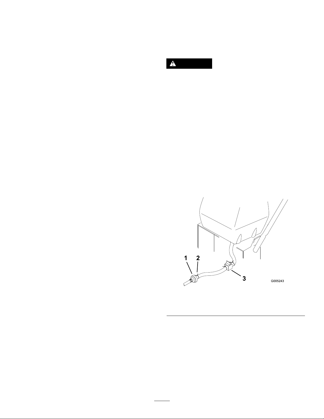
3.Closethefuelshut-offvalveatthefueltank(Figure27).
Figure27
1.Fuellter3.Fuelshut-offvalve
2.Clamp
4.Squeezetheendsofthehoseclamptogetherandslide
itupthefuellineawayfromfuellter(Figure27).
5.Pullthefuellineoffthefuellter(Figure27).
6.Openthefuelshut-offvalveandallowthegasolineto
drainintoagascanordrainpan.
Note:Nowisthebesttimetoinstallanewfuellter
becausethefueltankisempty.RefertoReplacingthe
FuelFilter(page25).
7.Installthefuellineontothefuellter.
24
Page 25
8.Slidethehoseclampclosetothevalvetosecurethe
fuelline.
ElectricalSystem
9.Wipeupanyspilledfuel.
ReplacingtheFuelFilter
ServiceInterval:Every200hoursoryearly,whichever
occursrst.
Neverinstalladirtylterifitisremovedfromthefuelline.
Note:Notehowthefuellterisinstalledinordertoinstall
thenewltercorrectly.
Note:Wipeupanyspilledfuel.
1.DisengagethePTOandsettheparkingbrake.
2.Stoptheengine,removethekey,andwaitforallmoving
partstostopbeforeleavingtheoperatingposition.
3.Closefuelshut-offvalveatthefueltank(Figure28).
4.Squeezetheendsofthehoseclampstogetherandslide
themawayfromthelter(Figure28).
Maintenance
ServicingtheFuses
Theelectricalsystemisprotectedbyfuses.Itrequiresno
maintenance.Ifafuseblows,checkthecomponentorcircuit
foramalfunctionorshort.
1.Removethecoverunderthecontrolpanel.
2.Pulloutonthefusetoremoveorreplaceit(Figure29).
3.Installthecoverunderthecontrolpanel.
Figure28
1.Hoseclamp3.Filter
2.Fuelline
5.Removethelterfromthefuellines.
6.Installanewlterandmovethehoseclampscloseto
thelter.
7.Openfuelshut-offvalveatfueltank(Figure28).
8.Checkforfuelleaksandrepairifneeded.
9.Wipeupanyspilledfuel.
Figure29
1.Fuse,10amp,bladetype2.Fuse,20amp,bladetype
25
Page 26
DriveSystem
Maintenance
AdjustingtheTracking
Ifthemachinedoesnottrackstraight,adjustmentisrequired.
1.Checkthereartirepressure.RefertoCheckingtheTire
Pressure(page26).
2.Loosenthewingnutsontherightcontrolrodand
rotatetheturnbuckleinorouttoensuretheright
controlleveriscenteredintheNeutral-Lockposition.
3.Securetheturnbuckleinpositionwiththewingnuts
(Figure30).
Figure30
Figure31
ReplacingtheCasterWheel ForkBushings
Thecasterwheelforksaremountedinbushingspressedinto
thetopandbottomofthecarrierframemountingpivot
tubes.Tocheckthebushings,movethecasterforksbackand
forthandside-to-side.Ifacasterforkisloose,thebushings
arewornandmustbereplaced.
1.Raisethecuttingunitsothecasterwheelsareoffthe
oor,thensupportthefrontofthemowerwithjack
stands.
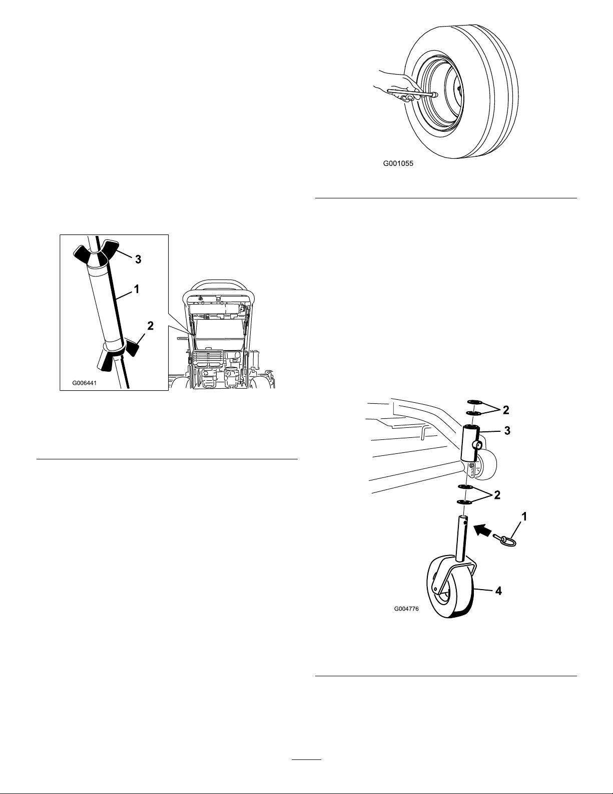
2.Removethelockingpinandspacer(s)fromthetopof
thecasterwheelfork(Figure32).
1.Turnbuckle
2.Bottomwingnut
4.Loosenthewingnutsontheleftcontrolrodandrotate
theturnbuckleinorouttochangethetracking.
5.Securetheturnbuckleinpositionwiththewingnuts
(Figure30).
6.Checkforpropertracking.
7.Adjusttheleftcontrolrodifachangeisneeded.
3.Topwingnut(lefthand
threaded)
CheckingtheTirePressure
ServiceInterval:Every50hoursormonthly,whichever
occursrst.
Checkthepressureatthevalvestem(Figure31).
Maintaintheairpressureinthereartiresat83to97kPa(12
to14psi).Uneventirepressurecancauseanunevencut.
Note:Thefronttiresaresemi-pneumatictiresanddonot
requireairpressuremaintenance.
Figure32
1.Lockingpin
2.Spacers4.Caster-wheelfork
3.Pullthecasterwheelforkoutofthemountingtube,
leavingthespacer(s)onthebottomofthefork.
4.Notethelocationofthespacersoneachforktoensure
correctinstallation,andtomaintainaleveldeck.
3.Carrier-framepivottube
26
Page 27
5.Insertapinpunchintothemountingtubeandcarefully
driveoutthebushings(Figure33).
Figure33
1.Mountingtube2.Bushing
6.Cleantheinsideofthemountingtube.
ServicingtheCasterWheel andBearings
Thecasterwheelsrotateonarollerbearingsupportedbya
spannerbushing.Ifthebearingiskeptwelllubricated,wear
willbeminimal.Failuretokeepthebearingwelllubricated
willcauserapidwear.Awobblycasterwheelusuallyindicates
awornbearing.
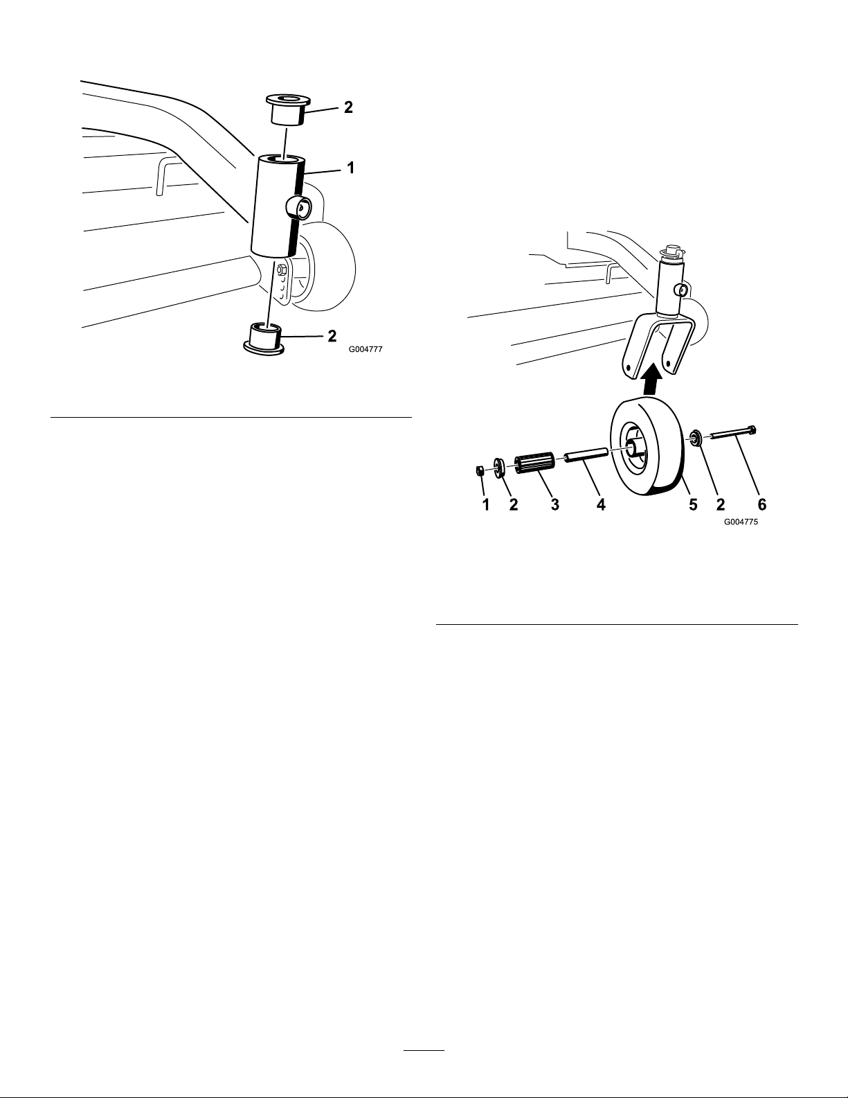
1.Removethelocknutandwheelboltholdingthecaster
wheeltothecasterfork(Figure34).
7.Greasetheinsideandoutsideofthenewbushings.
8.Useahammerandatplatetocarefullydrivethe
bushingsintothepivottubes.
9.Inspectthecasterwheelforkforwearandreplaceif
necessary(Figure33).
10.Slidethecasterwheelforkthroughthebushingsinthe
mountingtube.
11.Replacethespacer(s)ontotheforkandsecurewiththe
retainingring(Figure33).
Important:Theinsidediameterofthebushings
maycollapseslightlywheninstalled.Ifthecaster
wheelforkdoesnotslideintothenewbushings,
reambothbushingstoaninsidediameterof1.126
inch(29mm).
12.Greasethettingonthecarrierframepivottubes
usingNo.2general-purpose,lithium-basedor
molybdenum-basedgrease.
Figure34
1.Locknut
2.Wheelbolt5.Rollerbearing
3.Bushing
2.Remove1bushing,thenpullthespannerbushingand
rollerbearingoutofthewheelhub(Figure34).
3.Removetheotherbushingfromthewheelhuband
cleananygreaseanddirtfromthewheelhub(Figure
34).
4.Inspecttherollerbearing,bushings,spannerbushing,
andinsideofthewheelhubforwear;replaceany
defectiveorwornparts(Figure34).
5.Toassemble,place1bushingintothewheelhub.
Greasetherollerbearingandspannerbushingandslide
themintothewheelhub.
6.Placethesecondbushingintothewheelhub(Figure
34).
4.Spannerbushing
7.Installthecasterwheelintothecasterforkandsecure
withthewheelboltandlocknut.
8.Tightenthelocknutuntilthespannerbushingbottoms
againsttheinsideofthecasterforks(Figure34).
9.Greasethettingonthecasterwheel.
27
Page 28

AdjustingtheElectricClutch
CoolingSystem
ServiceInterval:Every100hours
Theclutchisadjustabletoensureproperengagementand
properbraking.
1.Inserta0.381–0.533mm(0.015–0.021inch)feeler
gaugethrough1inspectionslotinthesideofthe
assembly.
Note:Makesureitisbetweenthearmatureandthe
rotorfrictionsurfaces.
2.Tightenthelocknutsuntilthereisslightbindingon
thefeelergaugebutitcanbemovedeasilywithinthe
airgap(Figure35).
3.Repeatthisfortheremainingslots.
4.Checkeachslotagainandmakeslightadjustmentsuntil
thefeelergaugebetweentherotorandarmaturewith
veryslightcontactbetweenthem.
Maintenance
CleaningtheAirIntakeScreen
ServiceInterval:Beforeeachuseordaily
Removeanybuild-upofgrass,dirt,orotherdebrisfromthe
cylinderandcylinderheadcoolingns,airintakescreenon
ywheelend,andcarburetor-governorleversandlinkage.
Thiswillhelpensureadequatecoolingandcorrectengine
speedandwillreducethepossibilityofoverheatingand
mechanicaldamagetotheengine.
Figure35
1.Adjustingnut3.Feelergauge
2.Slot
28
Page 29
BrakeMaintenance
ServicingtheBrakes
1.Parkthemachineonalevelsurface,disengagethe
PTO,andsettheparkingbrake.
2.Stoptheengine,removethekey,andwaitforallmoving
partstostopbeforeleavingtheoperatingposition.
Alwayssettheparkingbrakewhenyoustopthemachine
orleaveitunattended.Iftheparkingbrakedoesnothold
securely,anadjustmentisrequired.
CheckingtheBrakes
ServiceInterval:Beforeeachuseordaily
Checkthebrakesonbothalevelsurfaceandslope.
1.Parkthemachineonalevelsurface,disengagethePTO.
2.Stoptheengine,removethekey,andwaitforallmoving
partstostopbeforeleavingtheoperatingposition.
3.Applytheparkingbrake.
Note:Settingtheparkingbrakeshouldtakea
reasonableamountofforce.Iftheparkingbrakedoes
notholdsecurely,adjustit.RefertoAdjustingthe
Brakes(page29).
Note:Whenthebrakeisengaged,thebrakehandle
shouldbeinthe1o'clockposition(Figure36).
3.Checkthebrakebeforeyouadjustit;refertoChecking
theBrakes(page29).
4.Releasetheparkingbrake;refertoReleasingthe
ParkingBrake(page13).
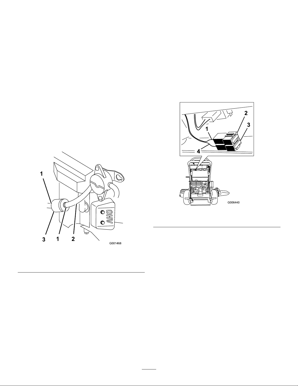
5.Loosenthetopandbottomjamnuts(Figure36).
6.Toadjustthebrake,removethehairpincotterand
clevispinfromthelowerbrakelever(Figure36).
7.Rotatethebrakerodintheyokes.
•Totightenthebrake,lengthentherodbetweenthe
yokes.
•Toloosenthebrake,shortentherodbetweenthe
yokes(Figure36).
Note:Thebrakerodshouldbethreadedintoboth
yokesthesamedistance.
8.Securetheyoketolowerbrakeleverwiththehairpin
cotterandclevispin(Figure36).
9.Tightenthetopandbottomjamnuts(Figure36).
10.Checkthebrakeoperationagain;refertoCheckingthe
Brakes(page29).
Figure36
1.Parkingbrakelever
(releasedposition)
2.Oneo'clockposition
3.Haripincotter7.Jamnut
4.Lowerbrakelever8.Brakerod
5.Clevispin
6.Yoke
AdjustingtheBrakes
Iftheparkingbrakedoesnotholdsecurely ,anadjustment
isrequired.
29
Page 30
BeltMaintenance
InspectingtheBelts
ServiceInterval:Every50hours
Checkthebeltsforcracks,frayededges,burnmarks,wear,
signsofoverheating,oranyotherdamage.Replaceany
damagedbelts.
ReplacingtheMowerBelt
Important:Thefastenersonthecoversofthismachine
aredesignedtoremainwiththecoverafterremoval.
1.DisengagethePTOandsettheparkingbrake.
2.Stoptheengine,removethekey,andwaitforallmoving
partstostopbeforeleavingtheoperatingposition.
3.Unlatchandremovethecarrierframecover.
4.Removethebeltcoverboltsandremovethebeltcover.
5.RemovethePTO-drivebelt.RefertoReplacingthe
PTO-DriveBelt(page30).
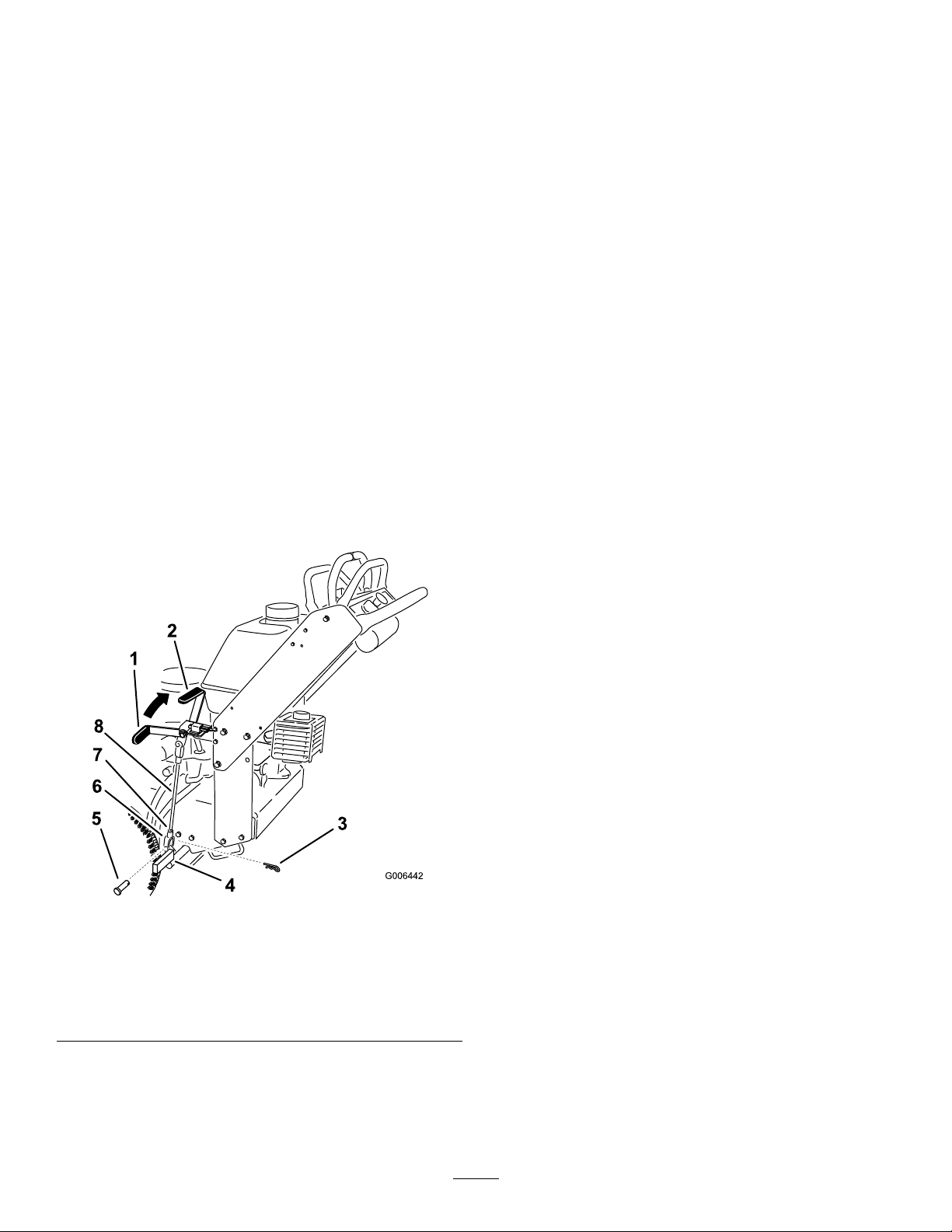
Figure37
1.Mowerdeckbelt4.Idlerarmspring
2.PTOdrivebelt
3.Drivebeltpulley
5.Drivebeltpulley
6.Disconnecttheidlerarmspringtorelievetensionon
theidlerarmandidlerpulley,thenremovetheworn
mowerbelt(Figure37).
7.Installthenewmowerbeltaroundthe2outsidespindle
pulleys,theidlerpulley,andinthelowergrooveofthe
doublespindlepulley(Figure37).
8.Connecttheidlerarmspring(Figure37).
9.InstallthePTO-drivebelt.RefertoReplacingthe
PTO-DriveBelt(page30).
10.Adjustthebeltguidean3mm(1/8inch)fromthebelt
(Figure37).
11.Installthebeltcoverontothecuttingunitandsecureit
withthebolts.
12.Installthecarrierframecoverontothecuttingunitand
securethelatches.
ReplacingthePTO-DriveBelt
Important:Thefastenersonthecoversofthismachine
aredesignedtoremainwiththecoverafterremoval.
1.DisengagethePTOandsettheparkingbrake.
2.Stoptheengine,removethekey,andwaitforallmoving
partstostopbeforeleavingtheoperatingposition.
3.Unlatchandremovethecarrierframecover.
4.Removethebeltcoverboltsandremovethebeltcover.
5.Removetheheatshieldfromtheenginedeckand
carrierframe.
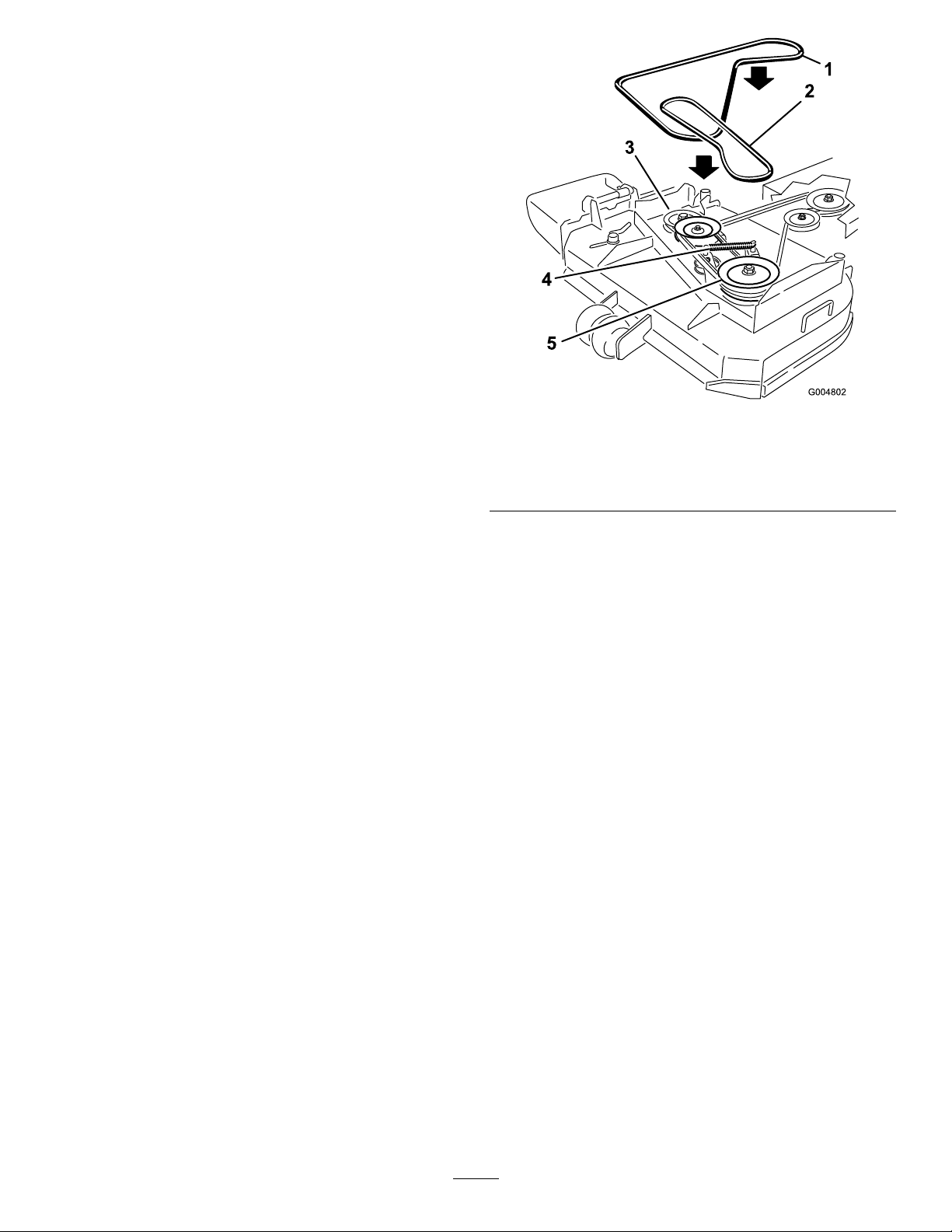
6.Rollthebeltoffofthecenterpulleyonthemower
deck(Figure38).
Important:Usecautionwhenremovingthebelt
astensionwillincreasebecauseofthespring
loadedidlerpulley.
7.Removethebeltfromtheenginepulleyandthespring
loadedidlerpulley(Figure38).
8.Installthenewbeltontotheenginepulleyandspring
loadedidlerpulley(Figure38).
9.Rollthebeltontothecenterpulleyonthemowerdeck
(Figure38).
Important:Usecautionwheninstallthebeltas
tensionwillincreasebecauseofthespringloaded
idlerpulley.
10.Installtheheatshieldtotheenginedeckandcarrier
frame.
30
Page 31
11.Installthebeltcoverontothecuttingunitandsecureit
withthebolts.
12.Installthecarrierframecoverontothecarrierframe
andsecurethelatches.
Figure38
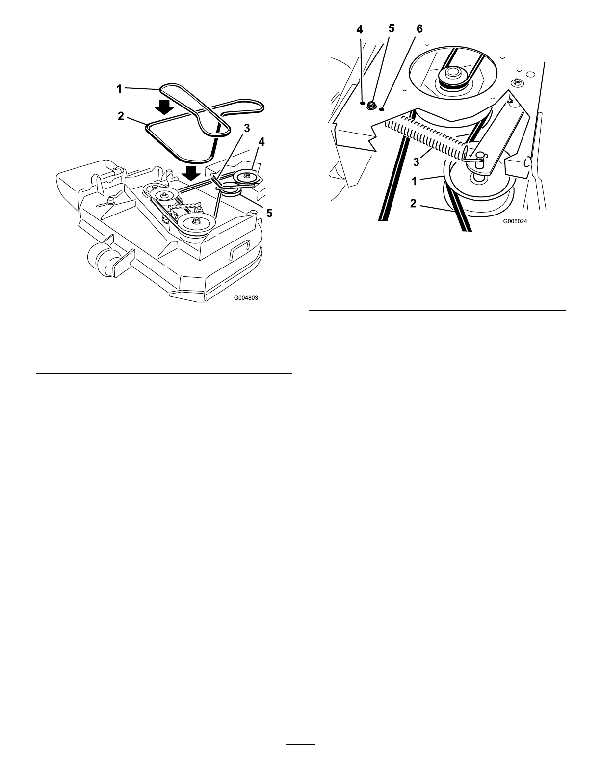
Figure39
1.PTO-drive-belt-idlerpulley4.Mosttensionforwornbelts
2.PTO-drivebelt5.Mediumtensionfornormal
3.Idlerspring
beltconditions
6.Leasttensionfornewbelts
1.Mowerdeckbelt
2.PTOdrivebelt
3.Idlerarmandspring
4.Clutchpulley
5.Idlerpulley
Adjustingthe PTO-Drive-Belt-Idler-Spring Anchor
ThepositionofthePTOidlercanbeadjustedtoincreaseor
decreasebelttension.
UseFigure39fortheidlerpositionoptions.
ReplacingthePump-DriveBelt
1.DisengagethePTOandsettheparkingbrake.
2.Stoptheengine,removethekey,andwaitforallmoving
partstostopbeforeleavingtheoperatingposition.
3.RemovethePTO-drivebelt.RefertoReplacingthe
PTO-DriveBelt(page30).
4.Raisethemachineandsupportitwithjackstands.
5.Disconnecttheclutchwireconnectorfromthewiring
harness.
6.Disconnecttheclutchretainerfromtheenginedeck
(Figure40).
31
Page 32
ControlsSystem
Maintenance
Adjustingthe Motion-Control-Handle Positions
AdjustingtheRightMotion-Control
Lever
Ifthemotion-controlleversdonotalignhorizontally ,adjust
therightmotion-controllever.
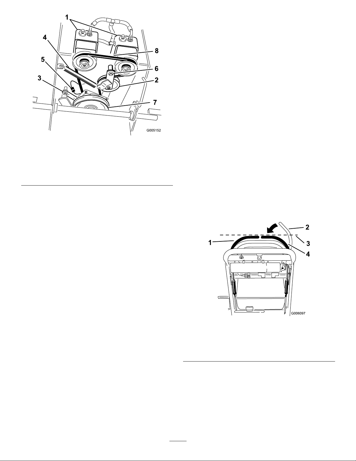
Figure40
1.Hydraulicpumps
2.Idlerpulley6.Pivotbolt
3.Clutchretainer
4.Tensionspring8.Pumpdrivebelt
7.Unhooktheidlerspringfromtheframe(Figure40).
8.Installthenewbeltaroundclutchandthe2drive
pulleys.
9.Installtheidlerspringbetweenidlerarmandframe
bracket(Figure40).
10.Installtheclutchretainertotheenginedeck(Figure40).
11.Connecttheclutchwireconnectortothewiring
harness.
12.InstallthePTO-drivebelt.
5.Clutchwireconnector
7.Drivepulley
Note:Adjustthehorizontalalignmentbeforethefrontto
backalignment.
1.DisengagethePTO,movetherightmotion-control
levertotheNeutralpositionandsettheparkingbrake.
2.Stoptheengine,removethekey,andwaitforallmoving
partstostopbeforeleavingtheoperatingposition.
3.Pushtherightmotion-controlleverdownoutof
Locked-Neutralposition(Figure41).
4.Checkifitalignshorizontallywiththeleft
motion-controllever(Figure41).
Figure41
1.Leftmotion-controllever3.Checkthehorizontal
2.Rightmotion-controllever
inNeutral-Lockedposition
Toadjusttherightmotion-controlleverhorizontally ,thecam
needstobeadjusted.
1.Removethecoverunderthecontrolpanel.
2.Loosenthenutandboltholdingthecam(Figure42).
32
alignmenthere
4.Rightmotion-controllever
Page 33
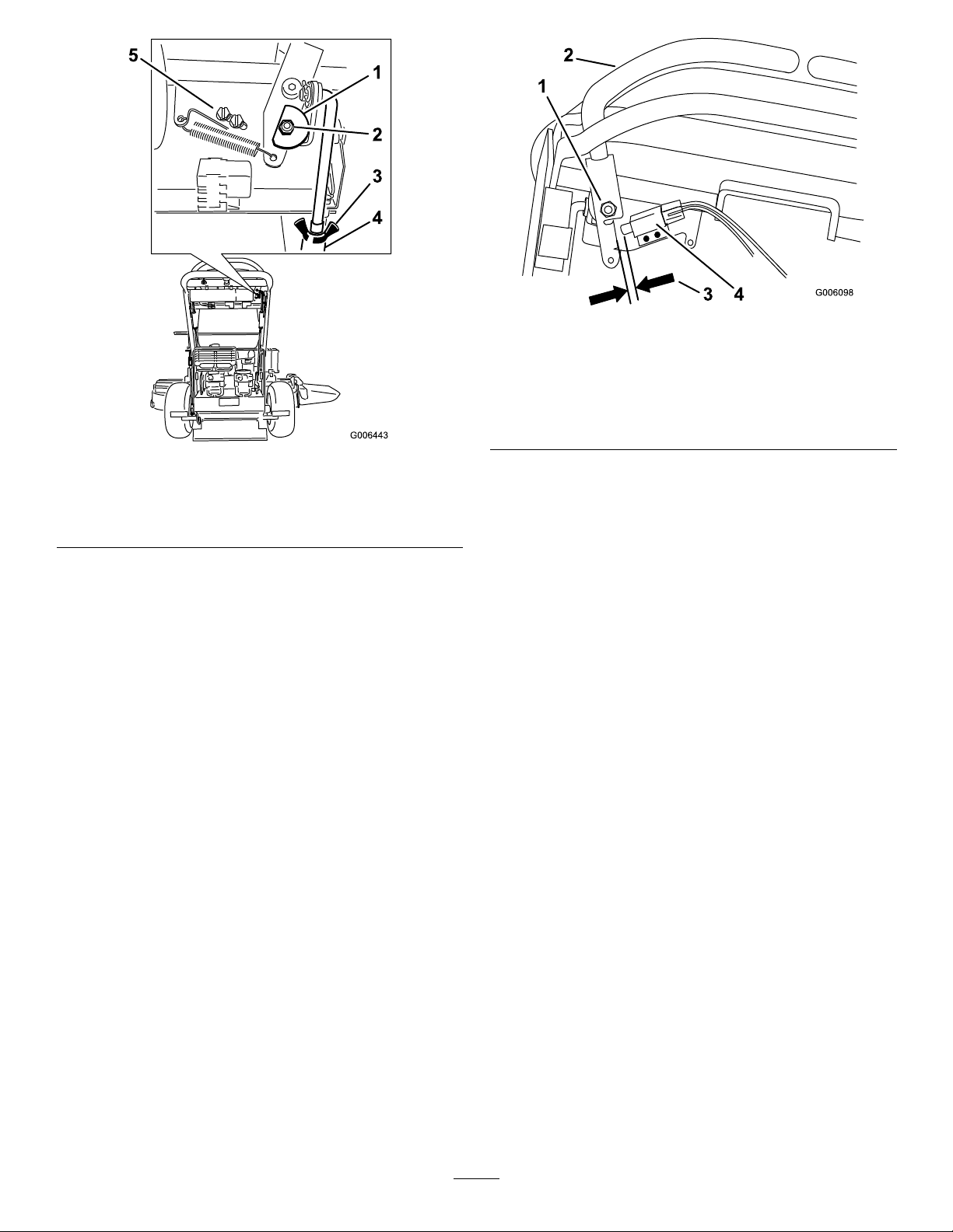
Figure43
Shownfromthefront
Figure42
1.Cam
2.Nutandbolt
3.Wingnut
4.Turnbuckle
5.Switchscrews
3.Adjustthecamuntilitalignswiththeleft
motion-controlleverandtightenthenutandboltfor
thecam.
Afterthecamisadjusted,theleverswitchneedstobe
checked.
1.Checkthegapbetweenthecontrolleverandswitchas
showninFigure43.
Note:Thegapneedstobean3mm(1/8inch).
1.Rightmotion-controllever
pivotshownundercontrols
2.Rightmotion-controllever
3.3mm(1/8inch)gap
neededbetweenswitch
andcontrollever
4.Switch
2.Ifneeded,loosenthescrewsholdingtheswitchand
adjusttheswitch(Figure43).
3.Tightenthescrewsandinstallthecoverunderthe
controlpanel.
AdjustingtheNeutralPositionforthe
Motion-ControlLevers
Important:Ensurethetrackingofthemoweriscorrect
afteradjustingthemotion-controllevers.Afteradjusting
thetracking,themotion-controlleversmaynotalignthe
exactlyfronttoback(Figure44).
Ifthemotion-controlleversdonotalignfronttoback,
ortherightcontrol-leverdoesnotmoveeasilyintothe
Neutral-Lockposition,adjustit.Adjusteachleverandcontrol
rodseparately.
Note:Adjustthehorizontalalignmentbeforethefrontto
backalignment.
1.Afterthehorizontalalignmentisnished,checkthe
fronttobackalignment(Figure44).
33
Page 34
HydraulicSystem
Maintenance
ServicingtheHydraulic System
FluidType:ToroHypr-Oil500syntheticmotoroilor
equivalentsyntheticoil.
Important:Useoilspeciedorequivalent.Otheruids
couldcausesystemdamage.
HydraulicSystemOilCapacity:2.0L(67oz)
Figure44
1.Leftmotion-controllever
2.Rightmotion-controllever4.Alignthecontrollevers
2.Loosenthewingnutsontherightcontrolrodand
rotatetheturnbuckleinorouttoensuretheright
controlleveriscenteredintheNeutral-Lockposition.
3.Securetheturnbuckleinpositionwiththewingnuts
(Figure45).
3.Neutral-Lockedposition
fronttobackhere
CheckingtheHydraulicFluid
ServiceInterval:Aftertherst8hours—Checkthe
hydraulicuid.
Every25hours—Checkthehydraulicuid.
Every200hours—Changethehydraulicuid.
Note:Thereare2waysofcheckingthehydraulicoil.One
iswhentheoiliswarmandoneiswhentheoiliscold.The
bafeinsidethetankhas2levelsdependingiftheoiliswarm
orcold.
1.Positionthemachineonalevelsurface.
2.Disengagethepowertakeoff(PTO)andshutoffthe
engine.
3.Waitforallmovingpartstostopbeforeleavingthe
operatingpositionandsettheparkingbrake.
4.Cleanareaaroundthecapandllerneckofthe
hydraulictank(Figure46).
Figure45
1.Turnbuckle
2.Bottomwingnut
4.Loosenthewingnutsontheleftcontrolrodandrotate
theturnbuckleinorouttochangethetracking.
5.Securetheturnbuckleinpositionwiththewingnuts
(Figure45).
6.Checkforpropertracking.Adjusttheleftcontrolrod
ifachangeisneeded.RefertoAdjustingtheTracking
(page26).
3.Topwingnut(lefthand
threaded)
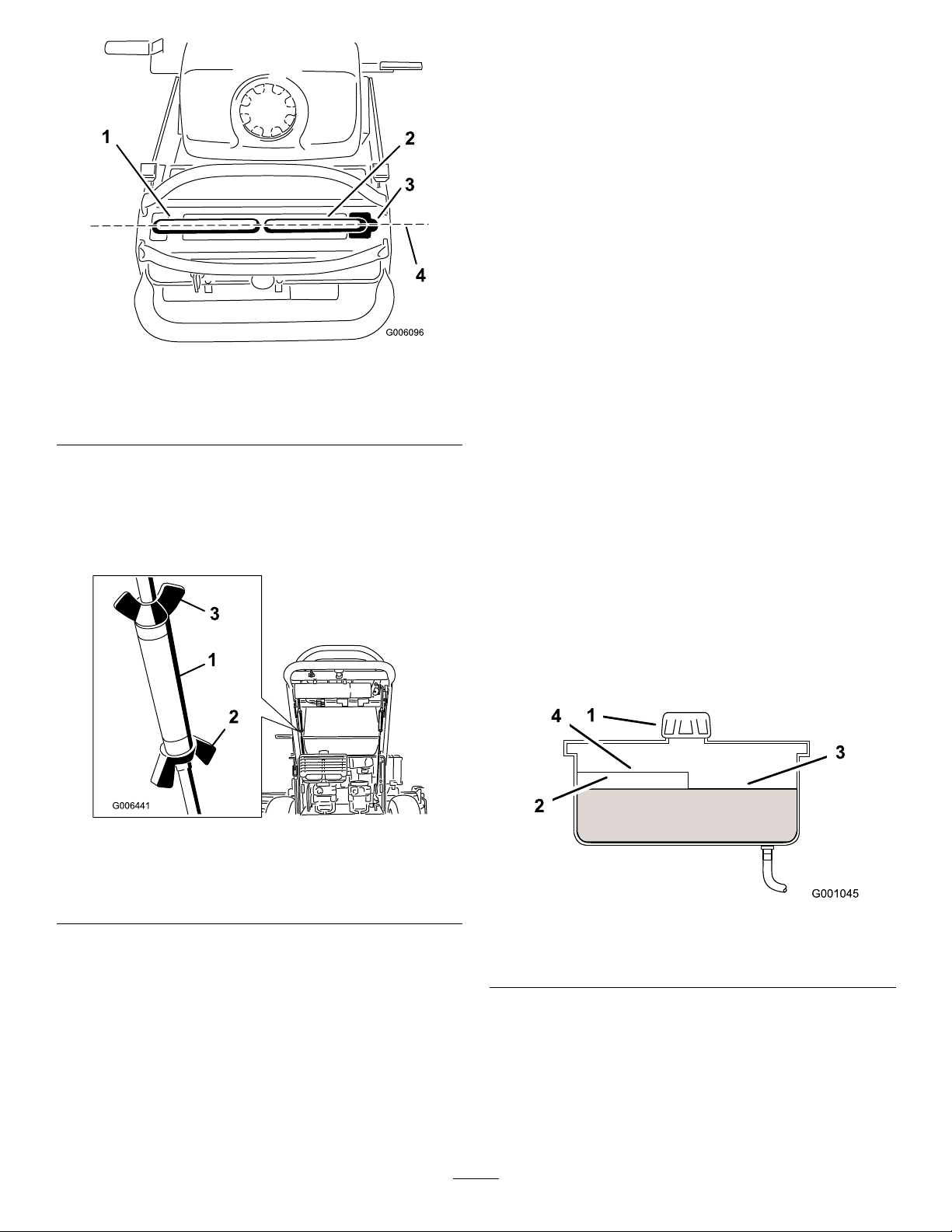
Figure46
1.Cap3.Colduidlevel—full
2.Bafe4.Hotuidlevel—full
5.Removethecapfromllerneckandchecktheuid
levelinthereservoir.(Figure46).
6.Adduidtothereservoiruntilitreachesthecoldlevel
ofthebafe.
7.Runthemachineatlowidlefor15minutestoallow
anyairtopurgeoutofthesystemandwarmtheuid.
RefertoStartingandStoppingtheEngine(page13).
34
Page 35
8.Rechecktheuidlevelwhiletheuidiswarm.Add
uidtothereservoiruntilitreachesthehotlevelof
thebafe.
Note:Theuidlevelshouldbetothetopofthehot
levelofthebafe,whentheuidiswarm(Figure46).
9.Installthecaponthellerneck.
WARNING
Hydraulicuidescapingunderpressurecan
penetrateskinandcauseinjury.
•Ifhydraulicuidisinjectedintotheskinit
mustbesurgicallyremovedwithinafew
hoursbyadoctorfamiliarwiththistype
ofinjury.Gangrenemayresultifthisis
notdone.
•Keepbodyandhandsawayfrompinhole
leaksornozzlesthatejecthighpressure
hydraulicuid.
•Usecardboardorpapertondhydraulic
leaks.
•Safelyrelieveallpressureinthehydraulic
systembeforeperforminganyworkonthe
hydraulicsystem.
•Makesureallhydraulicuidhosesand
linesareingoodconditionandallhydraulic
connectionsandttingsaretightbefore
applyingpressuretohydraulicsystem.
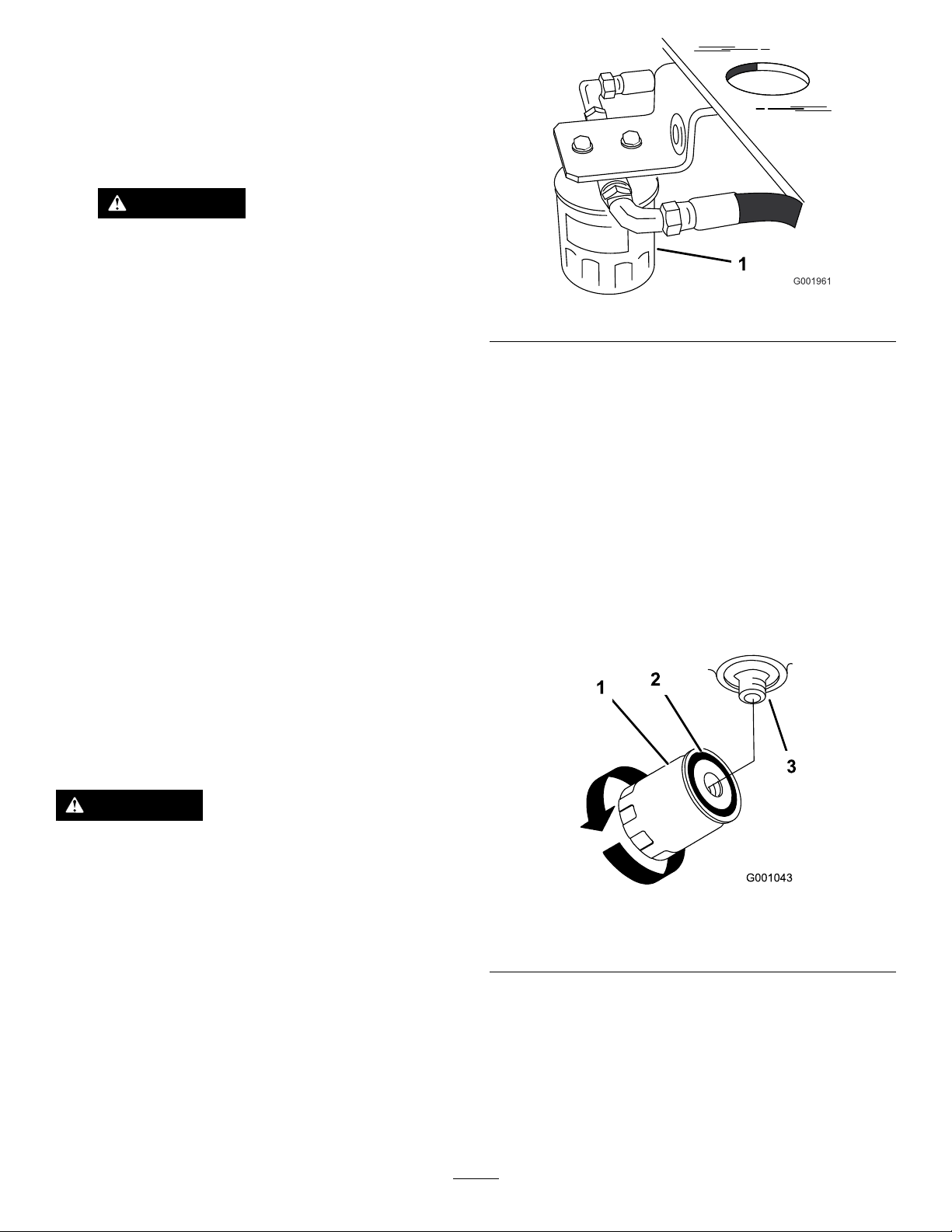
Figure47
5.Removetheoldlterandwipethelteradaptergasket
surfaceclean(Figure47).
6.Applyathincoathydraulicuidtotherubbergasket
onthereplacementlter.
7.Installthereplacementhydrauliclterontothelter
adapter.
Note:Donottighten.
8.Removetheplasticbagfromthereservoiropeningand
allowtheltertollwithhydraulicuid.
9.Whenthehydrauliclterisfull,turntheoillter
clockwiseuntiltherubbergasketcontactsthelter
adapter,thentightenthelteranadditional1/2turn
(Figure48).
ReplacingtheHydraulicFilter
ServiceInterval:Aftertherst8hours—Changethe
hydrauliclter.
Every200hours—Changethehydrauliclter.
WARNING
Hothydraulicuidcancausesevereburns.
Allowthehydraulicuidtocoolbeforeperforming
anymaintenancetothehydraulicsystem.
1.DisengagethePTOandsettheparkingbrake.
2.Stoptheengineandwaitforallmovingpartstostop
beforeleavingtheoperatingposition.
Important:Donotsubstituteautomotiveoillter
orseverehydraulicsystemdamagemayresult.
3.Removethehydraulicreservoircapandtemporarily
covertheopeningwithaplasticbagandrubberband
topreventallofthehydraulicuidfromdrainingout.
4.Locatethelterunderthefueltankandplaceadrain
panunderthelter(Figure47).
Figure48
1.Hydrauliclter
2.Gasket
10.Cleanupanyspilleduid.
11.Checktheuidinthereservoir,adduidtothetank
untilitreachesthecoldbafeofthetank.
Important:Useoilspeciedorequivalent.Other
uidscouldcausesystemdamage.
12.Starttheengineandletitrunforabout2minutesto
purgetheairfromthesystem.
3.Adapter
35
Page 36

13.Stoptheengineandcheckforleaks.
Note:If1orbothwheelswillnotdrive,referto
BleedingtheHydraulicSystem(page36).
14.Rechecklevelandadduid,ifrequired.Donot
overll.
BleedingtheHydraulicSystem
WARNING
Hydraulicuidescapingunderpressurecan
penetrateskinandcauseinjury.
•Ifhydraulicuidisinjectedintotheskinit
mustbesurgicallyremovedwithinafewhours
byadoctorfamiliarwiththistypeofinjury.
Gangrenemayresultifthisisnotdone.
Thesystemisselfbleeding,however,itmaybenecessary
tobleedthesystemiftheuidischangedorafterworkis
performedonthesystem.
1.DisengagethePTOandsettheparkingbrake.
2.Stoptheengineandwaitforallmovingpartstostop
beforeleavingtheoperatingposition.
3.Raisetherearofthemachineupontojackstandshigh
enoughtoraisethedrivewheelsofftheground.
4.Starttheengineandmovethethrottlecontroltothe
idleposition.
Ifthedrivewheeldoesnotrotate,itispossibletoassist
thepurgingofthesystembycarefullyrotatingthetire
intheforwarddirection.
5.Checkthehydraulicuidlevel.Asitdrops,adduidas
requiredtomaintaintheproperlevel.
6.Repeatthisprocedurefortheoppositewheel.
7.Thoroughlycleantheareaaroundeachofthecharge
pumphousings.
CheckingtheHydraulicLines
•Keepbodyandhandsawayfrompinholeleaks
ornozzlesthatejecthighpressurehydraulic
uid.
•Usecardboardorpapertondhydraulicleaks.
•Safelyrelieveallpressureinthehydraulicsystem
beforeperforminganyworkonthehydraulic
system.
•Makesureallhydraulicuidhosesandlinesare
ingoodconditionandallhydraulicconnections
andttingsaretightbeforeapplyingpressureto
hydraulicsystem.
ServiceInterval:Every100hours
Checkhydrauliclinesandhosesforleaks,loosettings,kinked
lines,loosemountingsupports,wear,weatherandchemical
deterioration.Makenecessaryrepairsbeforeoperating.
Note:Keepareasaroundhydraulicsystemcleanfromgrass
anddebrisbuildup.
36
Page 37
MowerDeck Maintenance
ServicingtheCuttingBlades
Toensureasuperiorqualityofcut,keepthebladessharp.For
convenientsharpeningandreplacement,keepextrablades
onhand.
WARNING
Awornordamagedbladecanbreak,andapiece
ofthebladecouldbethrownintotheoperator's
orbystander'sarea,resultinginseriouspersonal
injuryordeath.
•Inspectthebladesperiodicallyforwearor
damage.
•Replaceawornordamagedblade.
PreparingtoInspectorServicethe
Blades
CheckingforBentBlades
1.DisengagethePTO ,movethemotion-controlleversto
theNeutral-Lockedposition,andsettheparkingbrake.
2.Stoptheengine,removethekey,andwaitforallmoving
partstostopbeforeleavingtheoperatingposition.
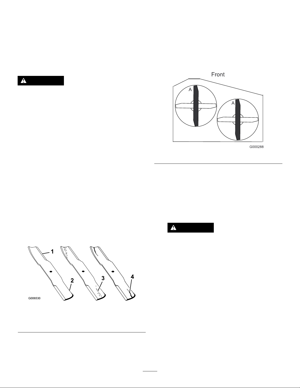
3.Rotatethebladesuntiltheendsfaceforwardand
backward.Measurefromalevelsurfacetothecutting
edge,positionA,oftheblades(Figure50).
Figure50
Parkthemachineonalevelsurface,disengagetheblades,and
settheparkingbrake.
TurntheignitionkeytotheOffposition.
Removethekeyanddisconnectthesparkplugwiresfrom
thesparkplugs.
InspectingtheBlades
1.Inspectthecuttingedges(Figure49).
Note:Iftheedgesarenotsharporhavenicks,remove
andsharpentheblades.RefertoSharpeningtheBlades
(page38).
Figure49
1.CuttingEdge3.Wear/slotformingin
curvedarea
2.Sail4.Crackinthecurvedarea
2.Inspecttheblades,especiallythecurvedarea(Figure
49).Ifyounoticeanycracks,wear,oraslotforming
inthisarea(item3.inFigure49),immediatelyinstall
anewblade.
4.Rotatetheoppositeendsofthebladesforward.
5.Measurefromalevelsurfacetothecuttingedgeof
thebladesatthesamepositionasinstep3above.
Thedifferencebetweenthedimensionsobtainedin
steps3and4mustnotexceed3mm(1/8inch).Ifthis
dimensionexceeds3mm(1/8inch),thebladeisbent
andmustbereplaced;refertoRemovingtheBlades
(page37)andInstallingtheBlades(page38).
WARNING
Abladethatisbentordamagedcouldbreak
apartandcouldseriouslyinjureorkillyouor
bystanders.
•Alwaysreplacebentordamagedblade
withanewblade.
•Neverleorcreatesharpnotchesinthe
edgesorsurfacesofblade.
RemovingtheBlades
Bladesmustbereplacedifasolidobjectishit,ifthebladeis
outofbalance,orisbent.T oensureoptimumperformance
andcontinuedsafetyconformanceofthemachine,use
genuineT ororeplacementblades.Replacementbladesmade
byothermanufacturersmayresultinnon-conformancewith
safetystandards.
1.Holdthebladeendusingaragorthickly-paddedglove.
2.Removethebladebolt,curvedwasher,bladestiffener,
andbladefromthespindle(Figure51).
37
Page 38
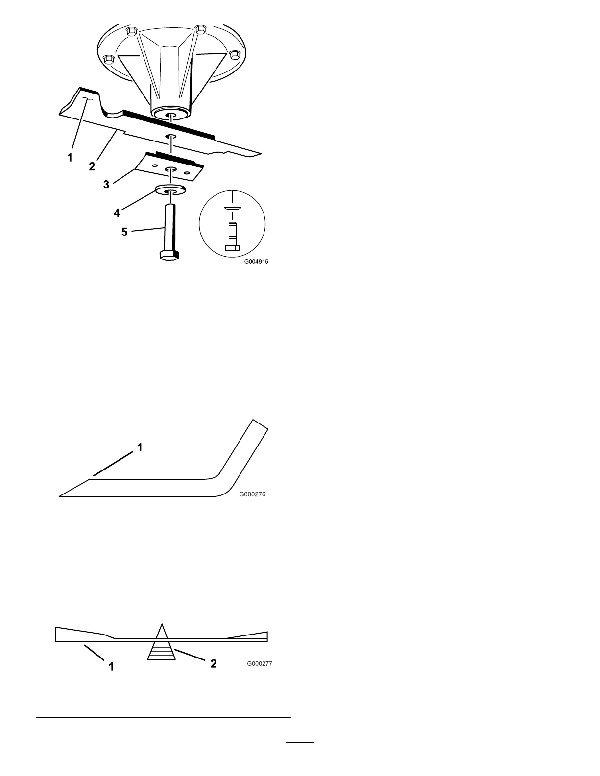
Figure51
1.Sailareaoftheblade4.Curvedwasher
2.Blade5.Bladebolt
3.Bladestiffener
SharpeningtheBlades
1.Usealetosharpenthecuttingedgeatbothendsof
theblade(Figure52).Maintaintheoriginalangle.The
bladeretainsitsbalanceifthesameamountofmaterial
isremovedfrombothcuttingedges.
InstallingtheBlades
Important:Thesailpartoftheblademustbepointing
upward,towardtheinsideofthemowertoensureproper
cutting(Figure53).
1.Installtheblade,stiffener,curvedwasher,andblade
bolttothespindle(Figure53).
2.Torquethebladeboltto115-140N-m(85-110ft-lb).
CorrectingtheMowerQuality ofCut
If1deckbladecutslowerthantheother,correctasfollows.
Note:Tireairpressureiscriticalintheseprocedures.Make
surealltireshavethecorrectpressure.
1.DisengagethePTOandsettheparkingbrake.
2.Stoptheengine,removethekey,andwaitforallmoving
partstostopbeforeleavingtheoperatingposition.
3.Disconnectthesparkplugwire(s)fromthespark
plug(s).
4.Adjustthetirepressureinthereartirestospecications;
refertoDriveSystemMaintenance(page26).
5.Checkthatthebladesandspindleshaftsarenotbent.
RefertoCheckingforBentBlades(page37).
6.Settheheight-of-cuttothe101.6mm(4inch)position.
RefertoAdjustingtheHeight-of-Cut(page17).
7.Performthestepsinthefollowingsections:Setting
uptheFrame(page38),CheckingtheMowerDeck
Front-to-RearPitch(page40),andCheckingthe
MowerDeckSide-to-SideHeight(page41).
Figure52
1.Sharpenatoriginalangle
2.Checkthebalanceofthebladebyputtingitonablade
balancer(Figure53).Ifthebladestaysinahorizontal
position,thebladeisbalancedandcanbeused.Ifthe
bladeisnotbalanced,lesomemetalofftheendof
thesailareaonly(Figure53).Repeatthisprocedure
untilthebladeisbalanced.
Figure53
1.Blade2.Balancer
SettinguptheFrame
CheckingtheCarrierFrameandEngine
DeckAlignment
Note:MisalignmentcancauseexcesswearonthePTO
drivebelt.
1.DisengagethePTOandsettheparkingbrake.
2.Stoptheengine,removethekey,andwaitforallmoving
partstostopbeforeleavingtheoperatingposition.
3.Placealongstraightedgeontopoftheenginedeckas
showninFigure54.
4.Atthecarrierframecrosschannel,measuretheheight
atlocationA(Figure54).
Note:Thismeasurementmustbe33mm(1-5/16
inch),plusorminus6mm(1/4inch).
5.IftheheightatlocationAisnotcorrect,adjustit.
6.Loosenthecarrierframemountingboltsonbothsides
ofthemachine(Figure54).
38
Page 39
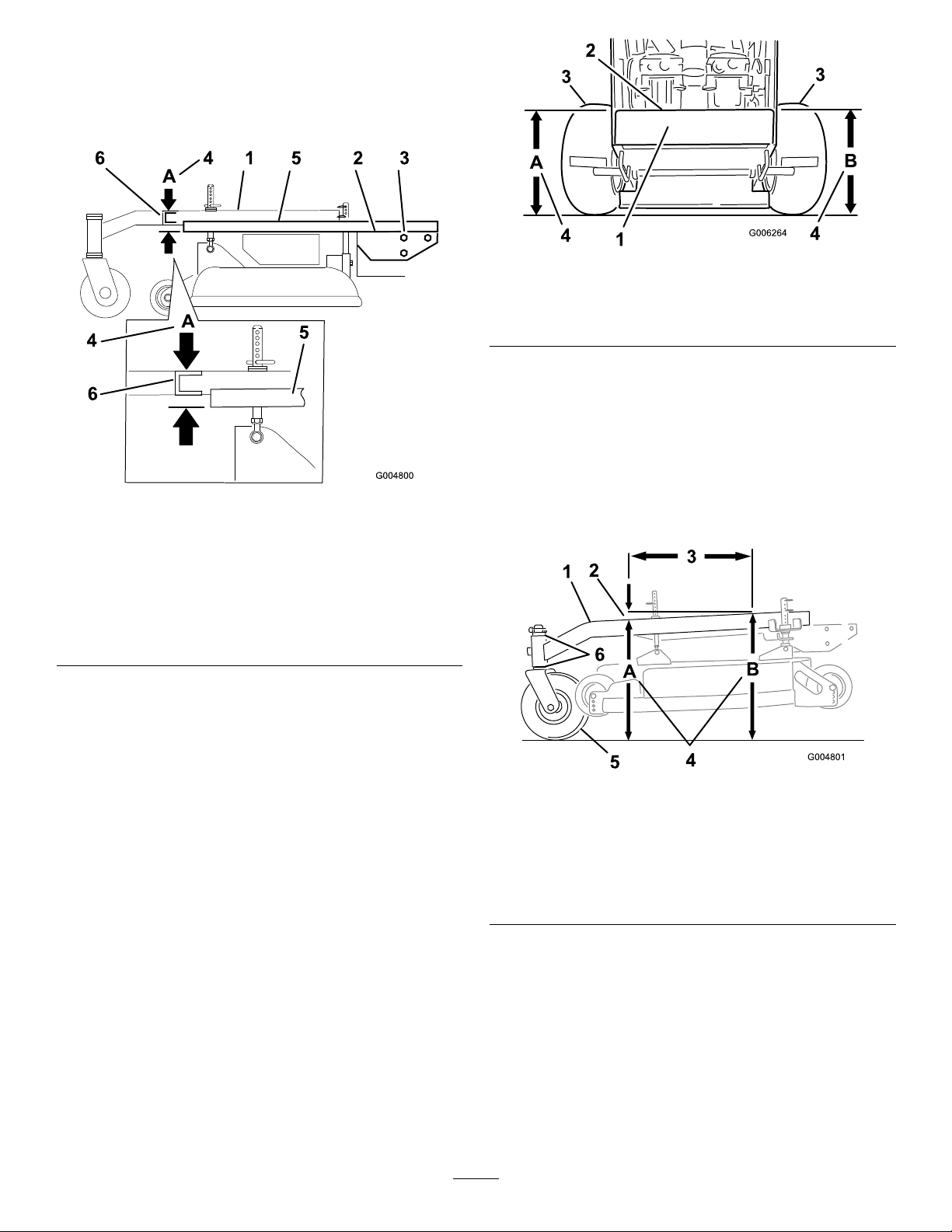
7.Alignthecarrierframeandenginedecktomatch33
mm(1-5/16inch),plusorminus6mm(1/4inch)at
locationA(Figure54).
8.Tightenthecarrierframemountingboltsonbothsides
ofthemachine.
Figure55
Figure54
1.Carrierframe4.LocationA,33mm(1-5/16
2.Topofenginedeck5.Straightedge
3.Carrierframemounting
bolts
inch)plusorminus6mm
(1/4inch)
6.Carrierframecross
channel
CheckingtheEngineDeckHeight
1.DisengagethePTOandsettheparkingbrake.
1.Backviewofmachine
2.Topofenginedeck4.Sameheightatlocations
3.Tires
AandB
CheckingtheCarrierFrame
Front-to-RearPitch
Thecarrierframemusthaveapitchbetween3mm(1/8inch)
to9mm(3/8inch)overthelengthof61cm(24inches)on
thecarrierframe(Figure56).
1.Measureout61cm(24inches)onthecarrierframe
(Figure56).
2.Stoptheengine,removethekey,andwaitforallmoving
partstostopbeforeleavingtheoperatingposition.
3.Adjustthetirepressureinthereartirestospecications;
refertoDriveSystemMaintenance(page26).
4.MeasureenginedeckheightatlocationA(Figure55).
5.MeasureenginedeckheightatlocationB(Figure55).
6.IftheheightatlocationAandBarenotthesame,
changetirepressureslightlytomakethemthesame.
Figure56
1.Carrierframe
2.3to10mm(1/8inchto3/8
inch)pitchover61cm(24
inch)length
3.61cm(24inches)6.Casterspacers
4.HeightatlocationsAand
B
5.Casterwheel
2.MeasurecarrierframeheightatlocationA(Figure56).
3.MeasurecarrierframeheightatlocationB(Figure56).
4.TheheightatlocationAmustbean3mmto10mm
(1/8to3/8inch)lowerthanlocationB(Figure56).
5.Ifthecarrierframeisnotcorrect,movethecaster
spacerstomakeitan3mmto10mm(1/8to3/8
inch)pitch(Figure56).
Note:Movespacersfromtoporbottomtomakethe
correctpitch.
39
Page 40
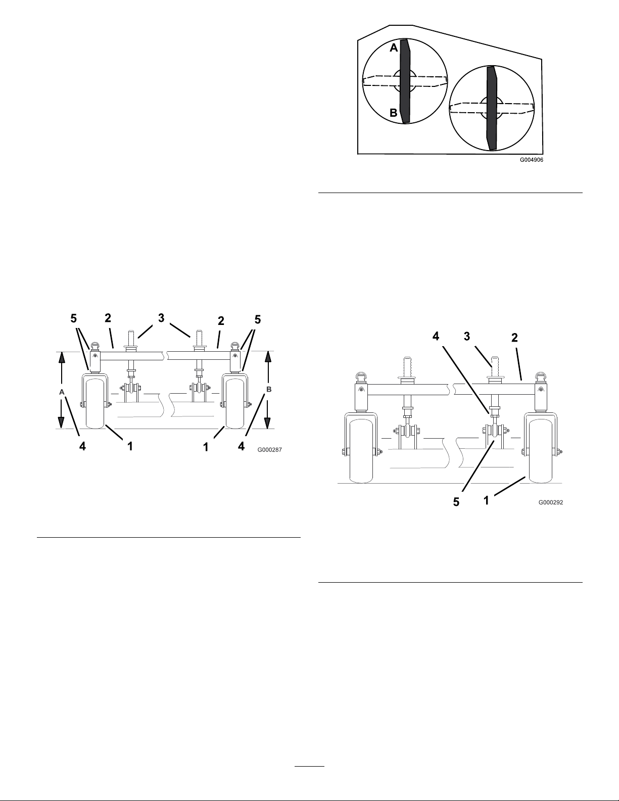
6.Thetirepressuremayalsobeadjustedslightlytomake
an3mmto10mm(1/8to3/8inch)pitch.
CheckingtheCarrierFrame
Side-to-SideHeight
Thecarrierframeneedstobeparallelside-to-sidefromthe
ground.
1.DisengagethePTOandsettheparkingbrake.
2.Stoptheengine,removethekey,andwaitforallmoving
partstostopbeforeleavingtheoperatingposition.
3.Adjustthetirepressureinthereartirestospecications;
refertoDriveSystemMaintenance(page26).
Figure58
4.MeasurecarrierframeheightatlocationA(Figure57).
5.MeasurecarrierframeheightatlocationB(Figure57).
Note:Ifthecarrierframeheightisnotthesamemove
spacersfromtoporbottomofcasterwheel,tomake
itlevel.Thetirepressuremayalsobeadjustedslightly
tomakeitlevel.
Figure57
1.Casterwheel4.Sameheightatlocations
AandB
2.Carrierframe5.Casterspacers
3.Frontheight-of-cutpins
ChangingtheMowerDeck Front-to-RearPitch
Changingthefront-to-rearpitchisdonebyadjustingthe
frontheight-of-cutposts.
Tochangethefront-to-rearpitch,thefrontheight-of-cut
postscanbeadjusted(Figure59).
Figure59
CheckingtheMowerDeck Front-to-RearPitch
1.Adjustthetirepressureinthereartirestospecications;
refertoDriveSystemMaintenance(page26).
2.Position1bladefront-to-rear.MeasureatAandB
locationsfromalevelsurfacetothecuttingedgeof
thebladetips(Figure58).
3.Themowerbladeshouldbea6mm(1/4inch)lower
infrontatAthanintherearatB.
4.Rotatebladesandrepeatforotherblades.Ifitis
notcorrect,proceedtoChangingtheMowerDeck
Front-to-RearPitch(page40).
1.Casterwheel
2.Carrierframe
3.Frontheight-of-cutpins
Toraisethefrontofthedeck,loosenjamnutandrotatethe
frontpinclockwise(Figure59).
Tolowerthefrontofthedeck,loosenjamnutandrotatethe
frontpincounterclockwise(Figure59).
1.Positionthebladesfront-to-rear.
2.MeasureatCandDlocations(Figure59)fromalevel
surfacetothecuttingedgeoftheblades.
3.Checktheside-to-sidelevelingofthecuttingunit.
4.Tightenthejamnuts(Figure59).
40
4.Jamnut
5.Balljoint
Page 41

CheckingtheMowerDeck Side-to-SideHeight
1.Adjustthereartirepressuretospecications;referto
DriveSystemMaintenance(page26).
2.Positionthebladesside-to-side.
3.MeasureatCandDlocationsfromalevelsurfaceto
thecuttingedgeofbladetips(Figure60).
Figure61
5.Themeasurementshouldbe102mm(4inches).
6.Ifitdoesnotmeasurecorrectly:
A.Adjustthereartirepressure.
B.Adjustthecasterforkspacers.
Figure60
4.ThedifferencebetweenmeasurementsCandDshould
benomorethan6mm(1/4inch).
ChangingtheMowerDeck Side-to-SideHeight
Changingtheside-to-sideheightisdonebyadjustingtherear
tirepressureandcasterspacers.
1.Changethereartirepressure.
Note:Dothistothecorrespondingsidethatneeds
adjustment.
2.Adjustthecasterspacer.
3.Recheckthefront-to-rearpitchandsidetosideleveling
ofthecuttingunit.
MatchingtheHeight-of-Cut
C.Adjustthefrontmower-deck-supportpins.
7.Checkthecarrierframefront-to-rearpitch.
1.Checkthereartirepressure.
2.Settheheight-of-cuttothe102mm(4inches)position
followingtheheight-of-cutdecal.
3.Withthemachineonlevelsurface,position1blade
front-to-rear.
4.MeasureatAandfromlevelsurfacetothecuttingedge
ofthebladetips(Figure61).
41
Page 42
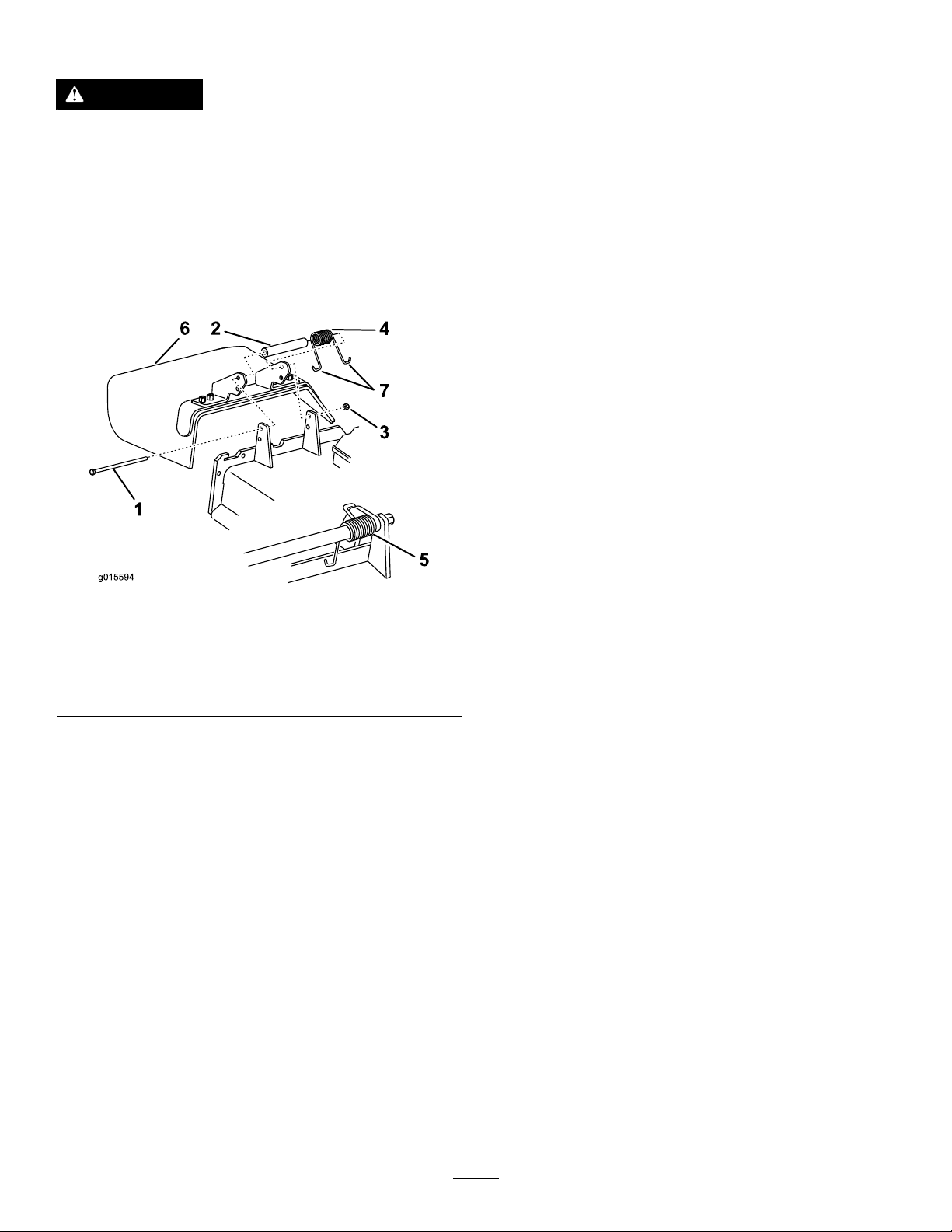
ReplacingtheGrassDeector
g015594
1
6 2
4
7
3
5
Cleaning
WARNING
Anuncovereddischargeopeningcouldallowthe
lawnmowertothrowobjectsatyouorbystanders,
resultinginseriousinjury.Also,contactwiththe
bladecouldoccur.
Neveroperatethelawnmowerunlessyouinstalla
coverplate,amulchplate,grassdeectororbagger.
1.Removethelocknut,bolt,springandspacerholding
thedeectortothepivotbrackets(Figure62).
CleaningundertheMower
ServiceInterval:Beforeeachuseordaily
Removethegrassbuildupunderthemowerdaily.
1.DisengagethePTO ,movethemotion-controlleversto
theNeutral-Lockedposition,andsettheparkingbrake.
2.Stoptheengine,removethekey,andwaitforallmoving
partstostopbeforeleavingtheoperatingposition.
3.Raisethefrontofthemachineandusejackstandsto
supportthemachine.
DisposingofWaste
Engineoil,batteries,hydraulicoil,andenginecoolantare
pollutantstotheenvironment.Disposeoftheseaccordingto
yourstateandlocalregulations.
Figure62
1.Bolt
2.Spacer6.Grassdeector
3.Locknut
4.Spring
2.Removedamagedorworngrassdeector.
3.Placespacerandspringontograssdeector.
4.Place1J-endofthespringbehindthedeckedge.
Note:Makesurethat1J-endofthespringisinstalled
behindthedeckedgebeforeinstallingtheboltas
showninFigure62.
5.Installboltandnut.
6.Place1J-hookendofthespringaroundthegrass
deector(Figure62).
Important:Thegrassdeectormustbeable
torotate.Liftthedeectoruptothefullyopen
positionandensurethatitrotatesintothefully
downposition.
5.Springinstalled
7.J-hookendofspring
42
Page 43

Storage
12.Paintallscratchedorbaremetalsurfaces.Paintis
availablefromyourAuthorizedServiceDealer.
CleaningandStorage
1.Disengagethepowertakeoff(PTO),settheparking
brake,andturntheignitionkeytooffandremovethe
key.
2.Removegrassclippings,dirt,andgrimefromthe
externalpartsoftheentiremachine,especiallythe
engine.
3.Cleandirtandchafffromtheoutsideoftheengine's
cylinderheadnsandblowerhousing.
Important:Youcanwashthemachinewithmild
detergentandwater.Donotpressurewashthe
machine.Avoidexcessiveuseofwater,especially
nearthedrivesystemandengine.Pressure
washingcanforcedirtandwaterintocriticalparts,
suchasspindlebearingsandelectricalswitches.
4.Checkthebrake;refertoCheckingtheBrakes(page
29).
5.Servicetheaircleaner;refertoServicingtheAir
Cleaner(page21).
6.Greasethemachine;refertoLubricatingtheMachine
(page20).
13.Storethemachineinaclean,drygarageorstoragearea.
Removethekeyfromtheignitionswitchandkeepit
inamemorableplace.Coverthemachinetoprotect
itandkeepitclean.
7.Changetheengineoil;refertoChangingtheEngine
Oil(page22).
8.Checkthetirepressure;refertoCheckingtheTire
Pressure(page26).
9.Forlong-termstorage:
A.Addstabilizer/conditioneradditivetofuelinthe
tank.
B.Runenginetodistributeconditionedfuelthrough
thefuelsystem(5minutes).
C.Stopengine,allowtocoolanddrainthefueltank;
refertoFuelSystemMaintenance(page24),or
operateengineuntilitstops.
D.Startengineandrununtilitstops.Repeat,on
Chokeuntiltheenginedoesnotstart.
E.Disposeoffuelproperly .Recycleasperlocal
codes.
Note:Donotstorestabilizer/conditioned
gasolineover90days.
10.Removethesparkplug(s)andcheckitscondition;refer
toServicingtheSparkPlugs(page23).Withthespark
plug(s)removedfromtheengine,pour2tablespoons
ofengineoilintothesparkplughole.Nowusethe
startertocranktheengineanddistributetheoilinside
thecylinder.Installthesparkplug(s).Donotinstallthe
wireonthesparkplug(s).
11.Checkandtightenallbolts,nuts,andscrews.Repairor
replaceanypartthatisdamagedordefective.
43
Page 44

Troubleshooting
Problem
Theenginewillnotstart,startshard,or
failstokeeprunning.
Theenginelosespower.
PossibleCauseCorrectiveAction
1.Thefueltankisempty.1.Fillthefueltankwithgasoline.
2.Thefuel-shutoffvalveisclosed.2.Openthefuel-shutoffvalve.
3.Thechokeisnotinthecorrectposition.
4.Theaircleanerisdirty.
5.Thespark-plugwireislooseor
disconnected.
6.Thesparkplugispittedorfouled,or
thegapisincorrect.
7.Thereisdirtinthefuellter.7.Replacethefuellter.
8.Dirt,water,orstalefuelisinthefuel
system.
1.Theengineloadisexcessive.1.Reducethegroundspeed.
2.Theaircleanerisdirty.
3.Theoillevelinthecrankcaseislow.3.Addoiltothecrankcase.
4.Thecoolingnsandairpassages
undertheengineblowerhousingare
plugged.
5.Thesparkplugispittedorfouled,or
thegapisincorrect.
6.Theventholeinthefuelcapisplugged.6.Cleanorreplacethefuelcap.
7.Thereisdirtinthefuellter.7.Replacethefuellter.
8.Dirt,water,orstalefuelisinthefuel
system.
3.Closethechokeiftheengineiscold;
openthechokeiftheengineiswarm.
4.Cleanorreplacetheair-cleaner
element.
5.Installthewireonsparkplug.
6.Installanew,correctlygappedspark
plug.
8.ContactanAuthorizedServiceDealer.
2.Cleantheair-cleanerelement.
4.Removetheobstructionfromthe
coolingnsandairpassages.
5.Installanew,correctlygappedspark
plug.
8.ContactanAuthorizedServiceDealer.
Theengineoverheats.
Themachinedoesnotdrive.
Thereisabnormalvibration.
Themachineproducesanunevencutting
height.
1.Theengineloadisexcessive.1.Reducethegroundspeed.
2.Theoillevelinthecrankcaseislow.2.Addoiltothecrankcase.
3.Thecoolingnsandairpassages
undertheengineblowerhousingare
plugged.
1.Theshiftleverisinneutral.1.Movetheshiftlevertoadrivegear
2.Thetractionbeltisworn,loose,or
broken.
3.Thetractionbeltisoffapulley.3.Changethebelt.
4.Theidlerspringisbrokenormissing.4.Replacethespring.
1.One/severalcuttingbladesis/arebent
orunbalanced.
2.Ablademountingboltisloose.2.Tightentheblademountingbolt.
3.Theenginemountingboltsareloose.3.Tightentheenginemountingbolts.
4.Theenginepulley,idlerpulley ,orblade
pulleyisloose.
5.Theenginepulleyisdamaged.
6.Thebladespindleisbent.
1.Theblade(s)is/arenotsharp.1.Sharpentheblade(s).
2.One/severalcuttingblade(s)is/are
bent.
3.Themowerisnotlevel.
4.Theundersideofthemowerisdirty.4.Cleantheundersideofthemower.
5.Thetirepressureisnotcorrect.5.Adjustthetirepressure.
6.Abladespindleisbent.
3.Removetheobstructionfromthe
coolingnsandairpassages.
position.
2.Changethebelt.
1.Installnewcuttingblade(s).
4.Tightentheappropriatepulley .
5.ContactanAuthorizedServiceDealer.
6.ContactanAuthorizedServiceDealer.
2.Installnewcuttingblade(s).
3.Levelthemowerfromside-to-sideand
front-to-rear.
6.ContactanAuthorizedServiceDealer.
44
Page 45

Problem
PossibleCauseCorrectiveAction
Thebladesdonotrotate.
1.Themowerdeckbeltiswornorloose.
2.Themowerdeckbeltisbroken.2.Installanewdeckbelt.
3.Themowerdeckbeltisoffpulley.3.Inspectthebeltandreplaceitifitis
4.Theidlerspringisbrokenormissing.4.Replacethespring.
1.Checkthebelttension.
damaged.Checkthepulleysandidlers
andadjustthebelttension.
45
Page 46

Notes:
46
Page 47

InternationalDistributorList
Distributor:
AgrolancKft
BalamaPrimaEngineeringEquip.HongKong85221552163
B-RayCorporation
CascoSalesCompany
CeresS.A.CostaRica
CSSCTurfEquipment(pvt)Ltd.SriLanka
CyrilJohnston&Co.
CyrilJohnston&Co.RepublicofIreland
EquiverMexico525553995444ParklandProductsLtd.NewZealand6433493760
FemcoS.A.Guatemala
ForGarderOU
G.Y .K.CompanyLtd.
GeomechanikiofAthensGreece
GolfinternationalTurizm
GuandongGoldenStarChina
HakoGroundandGardenSweden
HakoGroundandGarden
HayterLimited(U.K.)
HydroturfInt.CoDubai
HydroturfEgyptLLC
IrrimacPortugal351212388260T oroEuropeNVBelgium3214562960
IrrigationProductsInt'lPvtLtd.India0091442449
JeanHeybroekb.v.Netherlands3130639461 1VictusEmakPoland48618238369
Country:
Hungary3627539640
Korea82325512076
PuertoRico7877888383
NorthernIreland442890813121
Estonia3723846060
Japan81726325861
Turkey902163365993Riversa
Norway4722907760
UnitedKingdom441279723444
UnitedArabEmirates97143479479T-MarktLogisticsLtd.Hungary3626525500
Egypt2025194308ToroAustraliaAustralia61395807355
PhoneNumber:Distributor:
5062391138
94112746100
442890813121
5024423277
30109350054
862087651338
4635100000
4387
Country:
MaquiverS.A.Colombia
MaruyamaMfg.Co.Inc.
Mountelda.s.CzechRepublic
Mountelda.s.Slovakia
MunditolS.A.
NormaGarden
OslingerTurfEquipmentSA
OyHakoGroundandGarden
Ab
Perfetto
PratoverdeSRL.
Prochaska&Cie
RTCohen2004Ltd.
LelyTurfcare
SolvertS.A.S.
SpyprosStavrinidesLimitedCyprus
SurgeSystemsIndiaLimited
ValtechMorocco21253766
Japan81332522285
Argentina54114821
Russia749541 16120
Ecuador59342396970
Finland35898700733
Poland48618208416
Italy390499128
Austria4312785100
Israel97298617979
Spain
Denmark4566109200
France331308177
India911292299901
Phone
Number:
5712364079
420255704
220
420255704
220
9999
128
34952837500
00
35722434131
3636
EuropeanPrivacyNotice
TheInformationToroCollects
ToroWarrantyCompany(T oro)respectsyourprivacy .Inordertoprocessyourwarrantyclaimandcontactyouintheeventofaproductrecall,weaskyou
tosharecertainpersonalinformationwithus,eitherdirectlyorthroughyourlocalT orocompanyordealer .
TheT orowarrantysystemishostedonserverslocatedwithintheUnitedStateswhereprivacylawmaynotprovidethesameprotectionasapplies
inyourcountry.
BYSHARINGYOURPERSONALINFORMATIONWITHUS,YOUARECONSENTINGTOTHEPROCESSINGOFYOURPERSONALINFORMATION
ASDESCRIBEDINTHISPRIV ACYNOTICE.
TheWayT oroUsesInformation
Toromayuseyourpersonalinformationtoprocesswarrantyclaims,tocontactyouintheeventofaproductrecallandforanyotherpurposewhichwetell
youabout.ToromayshareyourinformationwithT oro'safliates,dealersorotherbusinesspartnersinconnectionwithanyoftheseactivities.Wewillnot
sellyourpersonalinformationtoanyothercompany.Wereservetherighttodisclosepersonalinformationinordertocomplywithapplicablelawsand
withrequestsbytheappropriateauthorities,tooperateoursystemsproperlyorforourownprotectionorthatofotherusers.
RetentionofyourPersonalInformation
Wewillkeepyourpersonalinformationaslongasweneeditforthepurposesforwhichitwasoriginallycollectedorforotherlegitimatepurposes
(suchasregulatorycompliance),orasrequiredbyapplicablelaw .
Toro'sCommitmenttoSecurityofY ourPersonalInformation
Wetakereasonableprecautionsinordertoprotectthesecurityofyourpersonalinformation.Wealsotakestepstomaintaintheaccuracyandcurrent
statusofpersonalinformation.
AccessandCorrectionofyourPersonalInformation
Ifyouwouldliketorevieworcorrectyourpersonalinformation,pleasecontactusbyemailatlegal@toro.com.
AustralianConsumerLaw
AustraliancustomerswillnddetailsrelatingtotheAustralianConsumerLaweitherinsidetheboxoratyourlocalT oroDealer.
374-0269RevH
Page 48

TheToroTotalWarranty
Landscape
Contractor
Equipment(LCE)
ConditionsandProductsCovered
TheT oroCompanyanditsafliate,T oroW arrantyCompany ,pursuanttoan
agreementbetweenthem,jointlypromisetotheoriginalpurchasertorepair
theT oroProductslistedbelowifdefectiveinmaterialsorworkmanship.
Thefollowingtimeperiodsapplyfromthedateofpurchasebytheoriginal
owner:
ProductsWarrantyPeriod
WalkBehindMowers
53cmMowers–Residentialuse
53cmMowers–Commercialuse
76cmMowers–Residentialuse
76cmMowers–Commercialuse
Mid-SizeWalk-BehindMowers
•Engine2years
GrandStand
®
Mowers
•Engine2years
•Frame
ZMaster
®
2000SeriesMowers
•Engine2years
•Frame
ZMaster
®
3000SeriesMowers
•Engine2years
•Frame
ZMaster
®
5000and6000Series
Mowers
•Engine2years
•Frame
ZMaster
®
7000SeriesMowers
•Engine2years
•Frame
AllMowers
•Battery2years
•Attachments2years
1
Residentialusemeansuseoftheproductonthesamelotasyourhome.Useatmorethanone
locationisconsideredcommercialuseandthecommercialwarrantywouldapply.
2
SomeenginesusedonT oroLCEProductsarewarrantedbytheenginemanufacturer.
3
Whicheveroccursrst.
4
LifetimeFrameW arranty-Ifthemainframe,consistingofthepartsweldedtogethertoformthe
tractorstructurethatothercomponentssuchastheenginearesecuredto,cracksorbreaksin
normaluse,itwillberepairedorreplacedunderwarrantyatnocostforpartsandlabor.Framefailure
duetomisuseorabuseandfailureorrepairrequiredduetorustorcorrosionarenotcovered.
Thiswarrantyincludesthecostofpartsandlabor,butyoumustpay
transportationcosts.
1
2years
1year
1
2years
1year
2years
2
5yearsor1,200hours
Lifetime(originalowneronly)
4yearsor500hours
2
Lifetime(originalowneronly)
5yearsor1,200hours
2
Lifetime(originalowneronly)
5yearsor1,200hours
2
Lifetime(originalowneronly)
5yearsor1,200hours
2
Lifetime(originalowneronly)
3
4
3
4
3
4
3
4
3
4
InstructionsforObtainingWarrantyService
IfyouthinkthatyourT oroProductcontainsadefectinmaterialsor
workmanship,followthisprocedure:
1.Contactyoursellertoarrangeserviceoftheproduct.Ifforanyreason
itisimpossibleforyoutocontactyourseller,youmaycontactany
ToroAuthorizedDistributortoarrangeservice.
2.Bringtheproductandyourproofofpurchase(salesreceipt)tothe
ServiceDealer.
3.IfforanyreasonyouaredissatisedwiththeServiceDealer’s
analysisorwiththeassistanceprovided,contactusat:
RLCCustomerCareDepartment
ToroWarrantyCompany
811 1LyndaleAvenueSouth
Bloomington,MN55420-1196
001-952-948-4707
SeeattachedDistributorList.
OwnerResponsibilities
YoumustmaintainyourT oroProductbyfollowingthemaintenance
proceduresdescribedintheOperator'sManual.Suchroutinemaintenance,
whetherperformedbyadealerorbyyou,isatyourexpense.
ItemsandConditionsNotCovered
Thereisnootherexpresswarrantyexceptforspecialemissionsystem
coverageandenginewarrantycoverageonsomeproducts.Thisexpress
warrantydoesnotcoverthefollowing:
•Costofregularmaintenanceserviceorparts,suchaslters,fuel,
lubricants,oilchanges,sparkplugs,airltersbladesharpeningorworn
blades,cable/linkageadjustments,orbrakeandclutchadjustments
•Componentsfailingduetonormalwear
•Anyproductorpartwhichhasbeenalteredormisusedorneglected
andrequiresreplacementorrepairduetoaccidentsorlackofproper
maintenance
•Pickupanddeliverycharges
•RepairsorattemptedrepairsbyanyoneotherthananAuthorizedT oro
ServiceDealer
•Repairsnecessaryduetofailuretofollowrecommendedfuel
procedure(consultOperator'sManualformoredetails)
–Removingcontaminantsfromthefuelsystemisnotcovered
–Useofoldfuel(morethanonemonthold)orfuelwhichcontains
morethan10%ethanolormorethat15%MTBE
–Failuretodrainthefuelsystempriortoanyperiodofnon-use
overonemonth
GeneralConditions
Thepurchaseriscoveredbythenationallawsofeachcountry.Therights
towhichthepurchaserisentitledwiththesupportoftheselawsarenot
restrictedbythiswarranty.
374-0272RevC
 Loading...