

Page 1

FormNo.3367-780RevA
CommercialWalk-Behind
TractionUnit
FixedDeck,PistolGrip,Hydro,Fittedwith
a48in(122cm),36in(91cm)or32in(81cm)
RearDischargeCuttingUnit
ModelNo.30033(TractionUnit)—SerialNo.311000001
andUp
ModelNo.02712(48in(122cm)CuttingUnit)—SerialNo.
311000001andUp
ModelNo.02711(36in(91cm)CuttingUnit)—SerialNo.
311000001andUp
ModelNo.02710(32in(82cm)CuttingUnit)—SerialNo.
311000001andUp
ToregisteryourproductordownloadanOperator'sManualorPartsCatalogatnocharge,gotowww.T oro.com.OriginalInstructions(EN)
Page 2
ThisproductcomplieswithallrelevantEuropean
directives,fordetailspleaseseetheseparateproduct
specicDeclarationofConformity(DOC)sheet.
Introduction
Thisrotary-blade,lawnmowerisintendedtobeused
byresidentialhomeownersorprofessional,hired
operators.Itisdesignedprimarilyforcuttinggrasson
well-maintainedlawnsonresidentialorcommercial
properties.Itisnotdesignedforcuttingbrushorfor
agriculturaluses.
Readthisinformationcarefullytolearnhowtooperate
andmaintainyourproductproperlyandtoavoidinjury
andproductdamage.Thismanualshouldbeconsidered
aspartofthemachine,asitcontains,safety ,operational
andmaintenanceinformation.Themowerisaprecision
builtmachinedesignedsolelyforcuttinggrassand
similarlowlyinggroundvegetationwithinthelimitations
statedinthismanual.Youareresponsibleforoperating
theproductproperlyandsafely .
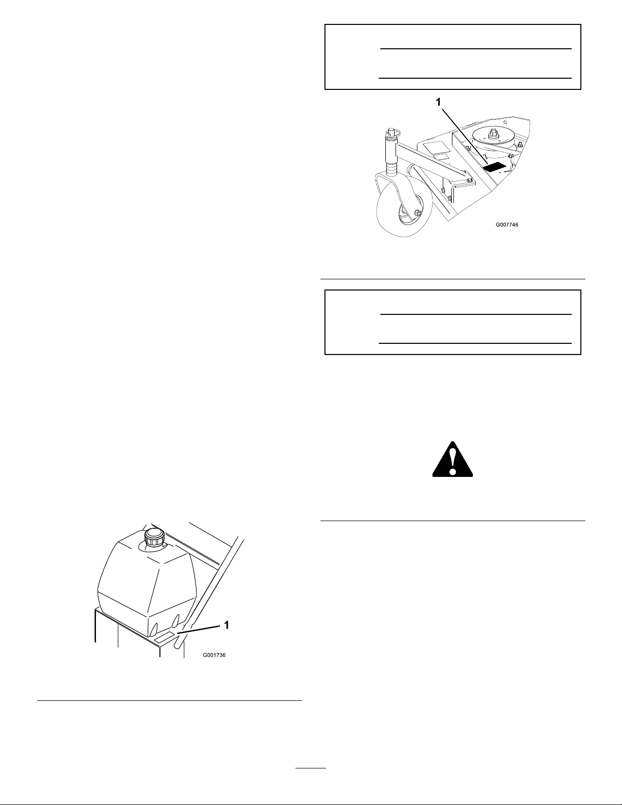
ModelNo.
SerialNo.
Figure2
1.Modelandserialnumberlocation
ModelNo.
YoumaycontactTorodirectlyforproductand
accessoryinformation,helpndingadealer,orto
registeryourproductatToroCommercialProducts
ServiceDepartmentSpellbrook,BishopsStortford,
CM234BU,England,+44(0)1279603019,Email:
uk.service@toro.com.
Wheneveryouneedservice,genuineToroparts,or
additionalinformation,contactanAuthorizedService
DealerorToroCustomerServiceandhavethemodel
andserialnumbersofyourproductready .
Figure1and
Figure2identifythelocationofthemodelandserial
numbersontheproduct.Writethenumbersinthe
spaceprovided.
SerialNo.
Thismanualidentiespotentialhazardsandhas
safetymessagesidentiedbythesafetyalertsymbol
Figure3),whichsignalsahazardthatmaycauseserious
(
injuryordeathifyoudonotfollowtherecommended
precautions.
Figure3
1.Safetyalertsymbol
Thismanualuses2otherwordstohighlightinformation.
Importantcallsattentiontospecialmechanical
informationandNoteemphasizesgeneralinformation
worthyofspecialattention.
1.Modelandserialnumberlocation
©2010—TheToro®Company
8111LyndaleAvenueSouth
Bloomington,MN55420
Figure1
Contactusatwww.Toro.com.
2
PrintedintheUSA.
AllRightsReserved
Page 3

Contents
Introduction.................................................................2
Safety...........................................................................4
GeneralLawnMowerSafety.................................4
SoundPressureforthe32RD,36RDand48
RD...................................................................6
SoundPowerforthe32RD ,36RDand48
RD...................................................................6
VibrationLevelforthe32RD...............................6
VibrationLevelforthe36RD...............................6
VibrationLevelforthe48RD...............................6
SlopeIndicator.....................................................7
SafetyandInstructionalDecals.............................8
Setup..........................................................................10
1CheckingtheFluidsandTyrePressure..............10
2ReadingtheManualandViewingthe
OperatorTrainingMaterial.............................10
ProductOverview......................................................11
Controls.............................................................11
Specications.....................................................12
Attachments/Acessories....................................12
Operation...................................................................13
AddingFuel.......................................................13
ThinkSafetyFirst...............................................14
OperatingtheParkingBrake...............................14
StartingandStoppingtheEngine........................14
OperatingtheNeutralLocks...............................15
OperatingtheMowerBladeControlKnob
(PTO)............................................................16
TheSafetyInterlockSystem................................16
DrivingtheMachineForwardand
Backward.......................................................17
BringingtheMachinetoNeutralPosition............18
StoppingtheMachine.........................................18
PushingtheMachinebyHand.............................18
TransportingMachines.......................................18
AdjustingtheHeight-of-Cut...............................18
AdjustingtheCasterPosition..............................19
AdjustingtheHandleHeight..............................20
HeightofCutChart............................................21
Maintenance...............................................................22
RecommendedMaintenanceSchedule(s)................22
Lubrication.............................................................22
HowtoGrease...................................................23
LubricatingtheCasterandWheel
Bearings.........................................................23
GreasingtheMowerBeltIdler............................23
GreasingthePumpControlandBell
Crank.............................................................23
EngineMaintenance...............................................24
ServicingtheAirCleaner....................................24
ServicingtheEngineOil.....................................25
ServicingtheSparkPlugs....................................26
FuelSystemMaintenance.......................................27
ServicingtheFuelTank......................................27
ServicingtheFuelFilter......................................28
DriveSystemMaintenance.....................................29
AdjustingtheSpeedControlLinkage..................29
AdjustingtheNeutralControlLinkages..............29
AdjustingtheHydroControlLinkages................30
AdjustingtheControlRod..................................32
AdjustingtheTracking.......................................33
AdjustingtheSpringAnchorLinks.....................33
CheckingtheTyrePressure.................................33
CoolingSystemMaintenance..................................34
CleaningtheAirIntakeScreen............................34
CleaningtheCoolingSystem...............................34
BrakeMaintenance.................................................34
ServicingtheBrake.............................................34
BeltMaintenance....................................................35
CheckingtheBelts..............................................35
ReplacingtheMowerBelt...................................35
AdjustingtheMowerBeltTension......................36
HydraulicSystemMaintenance...............................38
ServicingtheHydraulicSystem...........................38
MowerDeckMaintenance......................................41
ServicingtheCuttingBlades...............................41
AdjustingtheBladeBrake...................................42
Storage.......................................................................43
Troubleshooting.........................................................45
Schematics.................................................................47
3
Page 4

Safety
Improperlyusingormaintainingthismowercan
resultininjury.Toreducethepotentialforinjury,
complywiththesesafetyinstructions.
Torodesignedandtestedthismowerforreasonablysafe
service;however,failuretocomplywiththefollowing
instructionsmayresultinpersonalinjury.
Toensuremaximumsafety,bestperformance,and
togainknowledgeoftheproduct,itisessential
thatyouandanyotheroperatorofthemowerread
andunderstandthecontentsofthismanualbefore
theengineiseverstarted.Payparticularattention
tothesafetyalertsymbol(
Caution,Warning,orDanger—“personalsafety
instruction.”Readandunderstandtheinstruction
becauseithastodowithsafety.Failuretocomply
withtheinstructionmayresultinpersonalinjury.
GeneralLawnMowerSafety
ThefollowinginstructionshavebeenadaptedfromEN
836.
Figure3)whichmeans
•Ifgasolineisspilled,donotattempttostartthe
enginebutmovethemowerawayfromtheareaof
spillageandavoidcreatinganysourceofignition
untilgasolinevaporshavedissipated.
•Replaceallfueltankandcontainercapssecurely.
Preparation
•Whilemowing,alwayswearsubstantialfootwearand
longtrousers.Donotoperatetheequipmentwhen
barefootorwearingopensandals.
•Thoroughlyinspecttheareawheretheequipmentis
tobeusedandremoveallstones,sticks,wires,bones
andotherforeignobjects.
•Beforeusing,alwaysvisuallyinspecttoseethat
guards,andsafetydevices,suchasdeectorsarein
placeandworkingcorrectly .
•Beforeusing,alwaysvisuallyinspecttoseethatthe
blades,bladeboltsandcutterassemblyarenotworn
ordamaged.Replacewornordamagedbladesand
boltsinsetstopreservebalance.
Starting
Thiscuttingmachineiscapableofamputatinghands
andfeetandthrowingobjects.Failuretoobservethe
followingsafetyinstructionscouldresultinserious
injuryordeath.
Training
•Readtheinstructionscarefully.Befamiliarwiththe
controlsandtheproperuseoftheequipment.
•Neverallowchildrenorpeopleunfamiliarwiththese
instructionstousethemower.Localregulationscan
restricttheageoftheoperator.
•Keepinmindthattheoperatororuserisresponsible
foraccidentsorhazardsoccurringtootherpeopleor
theirproperty.
•Understandexplanationsforallpictogramsusedon
themowerorintheinstructions.
Gasoline
WARNING-Gasolineishighlyammable.Takethe
followingprecautions.
•Storefuelincontainersspecicallydesignedforthis
purpose.
•Refueloutdoorsonlyanddonotsmokewhile
refueling.
•Addfuelbeforestartingtheengine.Neverremove
thecapofthefueltankoraddgasolinewhilethe
engineisrunningorwhentheengineishot.
•Disengageallbladeanddriveclutchesandplaceinto
neutralbeforestartingtheengine.
•Donottiltmowerwhenstartingtheengineor
switchingonthemotor,unlessthemowerhastobe
tiltedforstarting.Inthiscase,donottiltitmorethan
absolutelynecessaryandliftonlythepart,whichis
awayfromtheoperator.
•Starttheengineorswitchonthemotorcarefully
accordingtoinstructionsandwithfeetwellaway
fromtheblade(s).
Operation
•Lightningcancausesevereinjuryordeath.If
lightningisseenorthunderisheardinthearea,do
notoperatethemachine;seekshelter.
•Nevermowwhilepeople,especiallychildren,orpets
arenearby.
•Mowonlyindaylightoringoodarticiallight.
•Avoidoperatingthelawnmowerinwetgrass,where
feasible.
•Stayalertforholesintheterrainandotherhidden
hazards.
•Neverdirectdischargeofmaterialtowards
bystanders.
•Donotputhandsorfeetnearorunderrotating
parts.
4
Page 5

•Neverpickuporcarryalawnmowerwhilethe
engineisrunning.
•Useextremecautionwhenreversingorpullinga
pedestriancontrolledlawnmowertowardsyou.
•Walk,neverrun.
•Slopes:
–Donotmowexcessivelysteepslopes.
–Exerciseextremecautionwhenonslopes.
–Mowacrossthefaceofslopes,neverupand
downandexerciseextremecautionwhen
changingdirectiononslopes.
–Alwaysbesureofyourfootingonslopes.
•Neveroperatethelawnmowerwithdamagedguards,
orwithoutsafetydevices,forexampledeectors
and/orgrasscatchers,inplace.
•Uselowthrottlesettingswhenengagingthe
traction-clutch,especiallyinhighgears.Reduce
speedonslopesandinsharpturnstoprevent
overturningorlossofcontrol.
•Stopthebladeifthelawnmowerhastobetiltedfor
transportationwhencrossingsurfacesotherthan
grassandwhentransportingthelawnmowertoand
fromtheareatobemowed.
•Donotoperatetheengineinaconnedspacewhere
dangerouscarbonmonoxidefumescancollect.
•Stoptheengineandwhereakeyisttedremovethe
key,makesurethatallmovingpartshavecometoa
completestop:
–wheneveryouleavethelawnmower.
–beforerefueling.
–beforeremovingthegrasscatcher.
–beforemakingheightadjustmentunless
adjustmentcanbemadefromtheoperator’s
position.
•Stoptheengineandwhereakeyisttedremovethe
key,makesurethatallmovingpartshavecometoa
completestop,anddisconnectthesparkplugwire:
–beforeclearingblockagesoruncloggingchute.
–beforechecking,cleaningorworkingonthelawn
mower.
–afterstrikingaforeignobject,inspectthelawn
mowerfordamageandmakerepairsbefore
restartingandoperatingthelawnmower.
–iflawnmowerstartstovibrateabnormally(check
immediately).
•Reducethethrottlesettingduringengineshutdown
and,iftheengineisprovidedwithashut-offvalve,
turnthefueloffattheconclusionofmowing.
•Usecarewhenusingsulkies,and
–useonlyapproveddrawbarhitchpoints.
–limitloadstothoseyoucansafelycontrol.
–donotturnsharply:usecarewhenreversing.
–donotcarrypassengers.
•Watchoutfortrafcwhencrossingornearroadways.
•Beforeleavingtheoperator’sposition
–disengagethepowertake-offandlowerthe
attachments.
–placeintoneutralandsettheparkingbrake.
–stoptheengineandremovethekey.
MaintenanceandStorage
•Keepallnuts,boltsandscrewstighttobesurethe
equipmentisinsafeworkingcondition.
•Donotusepressurecleaningequipmentonmachine.
•Neverstoretheequipmentwithgasolineinthetank
andinsideabuildingwherefumescanreachanopen
ameorspark.
•Allowtheenginetocoolbeforestoringinany
enclosure.
•Toreducetherehazard,keeptheengine,silencer,
batterycompartmentandgasolinestoragearefreeof
grass,leaves,orexcessivegrease.
•Checkthedischargeguardfrequentlyandreplace
withmanufacturer’srecommendedparts,when
necessary.
•Replacewornordamagedpartsforsafety.
•Replacefaultysilencers.
•Ifthefueltankhastobedrained,dothisout-doors.
•Donotchangetheenginegovernorsettingsor
overspeedtheengine.Operatinganengineat
excessivespeedcanincreasethehazardofpersonal
injury.
•Onmultibladedlawnmowers,takecareasrotating
oneblademaycauseotherstorotate.
•Becarefulduringadjustmentofthelawnmowerto
prevententrapmentofthengersbetweenmoving
bladesandxedpartsofthelawnmower.
•Toensurethebestperformanceandsafety,
purchaseonlygenuineTororeplacementparts
andaccessories.Donotuse
accessories;theymaycauseasafetyhazard.
will t
partsand
5
Page 6

SoundPressureforthe32RD,
VibrationLevelforthe48RD
36RDand48RD
The32RDhasasoundpressurelevelattheoperator’s
earof91dBA,whichincludesanUncertaintyValue(K)
of1dBA.
The36RDhasasoundpressurelevelattheoperator’s
earof85dBA,whichincludesanUncertaintyValue(K)
of1dBA.
The48RDhasasoundpressurelevelattheoperator’s
earof88dBA,whichincludesanUncertaintyValue(K)
of1dBA.
Thesoundpressurelevelwasdeterminedaccordingto
theproceduresoutlinedinEN836.
SoundPowerforthe32RD,36
RDand48RD
The32RDand36RDhasaguaranteedsoundpower
levelof100dBA,whichincludesanUncertaintyValue
(K)of1dBA.
Hand-Arm
Measuredvibrationlevelforrighthand=2.0m/s
Measuredvibrationlevelforlefthand=2.0m/s
UncertaintyValue(K)=1.0m/s
Measuredvaluesweredeterminedaccordingtothe
proceduresoutlinedinEN836.
2
2
2
The48RDhasaguaranteedsoundpowerlevelof105
dBA,whichincludesanUncertaintyValue(K)of1dBA.
Thesoundpowerlevelwasdeterminedaccordingtothe
proceduresoutlinedinISO11094.
VibrationLevelforthe32RD
Hand-Arm
Measuredvibrationlevelforrighthand=3.7m/s
Measuredvibrationlevelforlefthand=3.4m/s
UncertaintyValue(K)=1.0m/s
Measuredvaluesweredeterminedaccordingtothe
proceduresoutlinedinEN836.
2
2
VibrationLevelforthe36RD
Hand-Arm
Measuredvibrationlevelforrighthand=1.5m/s
2
2
Measuredvibrationlevelforlefthand=2.0m/s
UncertaintyValue(K)=1.0m/s
Measuredvaluesweredeterminedaccordingtothe
proceduresoutlinedinEN836.
2
2
6
Page 7
SlopeIndicator
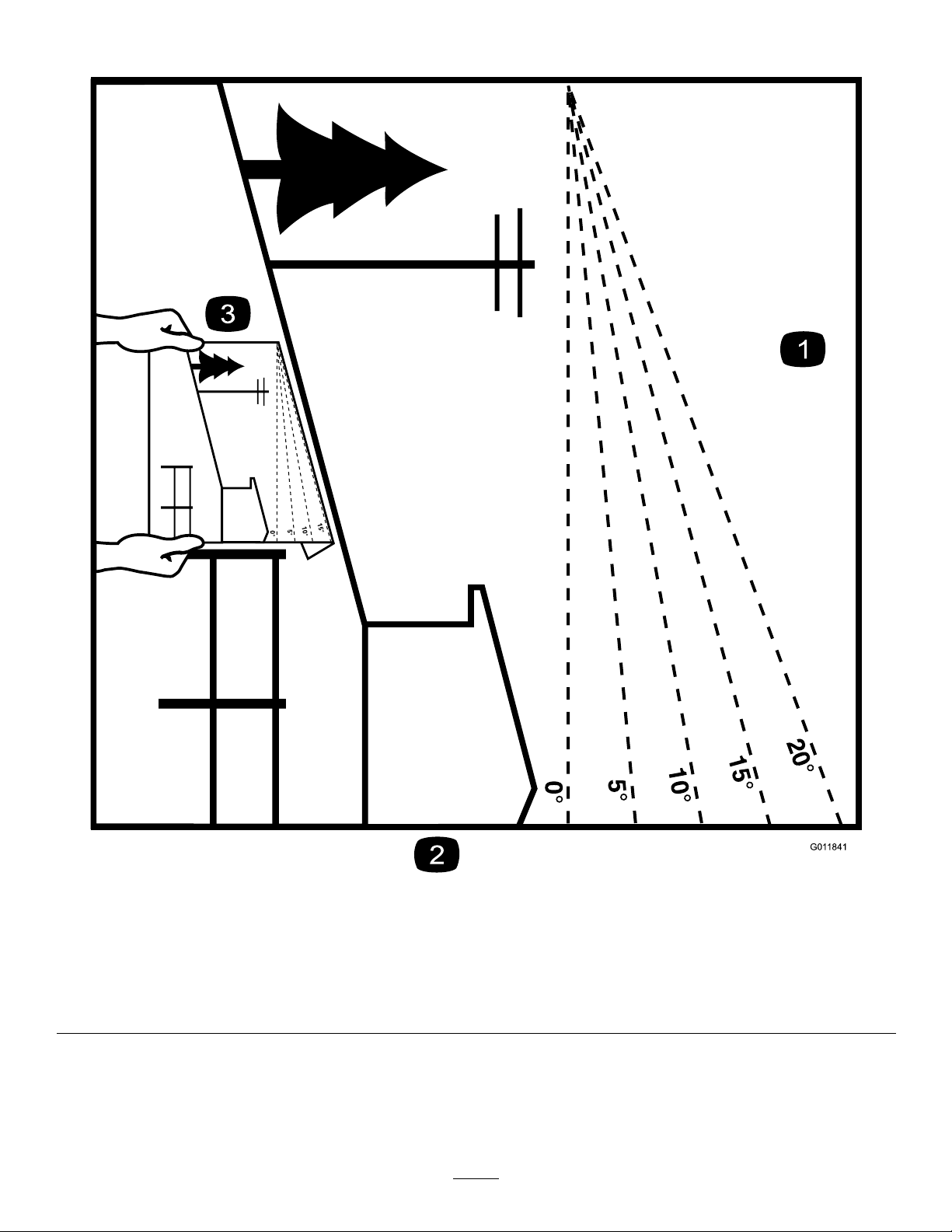
G011841
Figure4
Thispagemaybecopiedforpersonaluse.
1.Themaximumslopeyoucansafelyoperatethemachineonis20degrees.Usetheslopecharttodeterminethedegreeofslope
ofhillsbeforeoperating.Donotoperatethismachineonaslopegreaterthan20degrees.Foldalongtheappropriateline
tomatchtherecommendedslope.
2.Alignthisedgewithaverticalsurface,atree,building,fencepole,etc.
3.Exampleofhowtocompareslopewithfoldededge.
7
Page 8
SafetyandInstructional
Decals
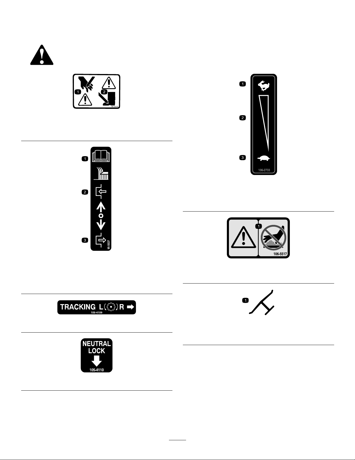
1.Cuttinghazardofhand
2.Cuttinghazardoffoot
Safetydecalsandinstructionsareeasilyvisibletotheoperatorandarelocatednearanyareaof
potentialdanger.Keepsafetysignsclearandvisible,replaceanydecalthatisdamagedorlost.
40-13–010
106-2733
1.Fast
2.Continuousvariable
setting
3.Slow
1.ReadtheOperator’s
Manualforinstructionson
operatingthecuttingblade
2.Pullbacktodisengage
95-5537
105-4109
105-4110
3.Pushforwardtoengage
106-5517
1.Warning–DoNottouchthehotsurface.
Manufacturer’sMark
1.Indicatesthebladeisidentiedasapartfromtheoriginal
machinemanufacturer .
8
Page 9
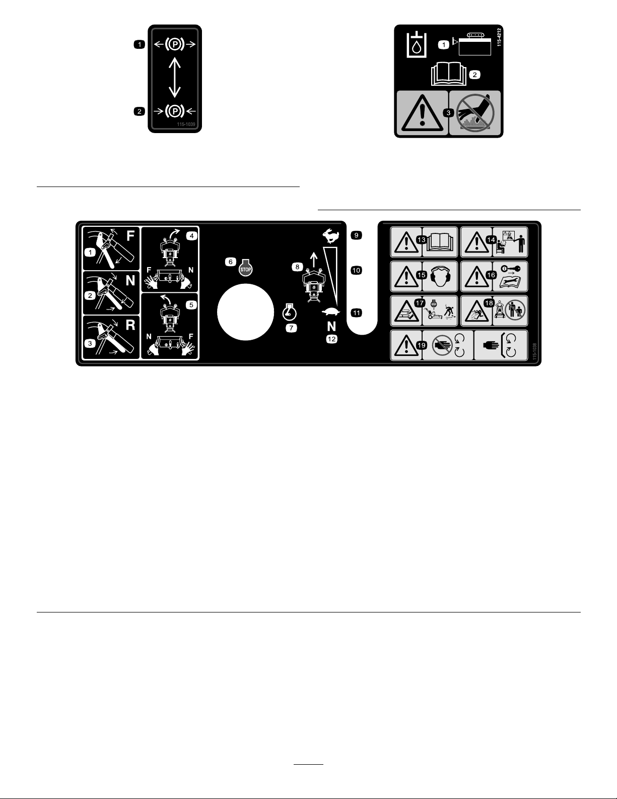
115-1039
1.Parking
brake—disengaged
2.Parkingbrake—engaged
1.Hydraulicoillevel3.Warning—donottouch
2.ReadtheOperator’s
Manual.
115-4212
115-1038
1.Forward
2.Neutral
3.Reverse
4.Toturnrightmovethelefthandleverintotheforwardpositionwhiletherighthandleverisintheneutralposition.
5.Toturnleftmovetherighthandleverintotheforwardpositionwhilethelefthandleverisintheneutralposition.
6.Engine—stop
7.Engine—run
8.Groundspeed
9.Fast
10.Continuousvariablesetting
11.Slow
12.Neutral
13.Warning—readtheOperator’sManual.
14.Warning—donotoperatethismachineunlessyouaretrained.
15.Warning—wearhearingprotection.
16.Warning—removetheignitionkeybeforeperformingmaintenanceonthemachine.
17.Cutting/dismembermenthazardofhandorfoot,mowerblade—stoptheenginebeforeleavingtheoperatingposition.
18.Thrownobjecthazard—keepbystandersasafedistancefromthemachine.
19.Warning—stayawayfrommovingparts;keepallguardsinplace.
thehotsurface.
9
Page 10

Setup
LooseParts
Usethechartbelowtoverifythatallpartshavebeenshipped.
ProcedureDescription
1
2
Note:Determinetheleftandrightsidesofthemachinefromthenormaloperatingposition.
Nopartsrequired
Operator’sManual
EngineOperator’sManual
PartsCatalog
Operatortrainingmaterial
RegistrationCard
Oildrainhose
1
CheckingtheFluidsandTyre
Pressure
ReadingtheManualand
ViewingtheOperatorTraining
Qty.
–
1
1
1
1
1
1
2
Material
NoPartsRequired
Use
Checktheuidsandtyrepressure.
ReadtheOperator’sManualandwatch
theoperatortrainingmaterialbefore
operatingthemachine.
Procedure
•Beforeyoustarttheengineandusethemachine,
checktheoillevelintheenginecrankcase;referto
CheckingtheEngineOilLevel.
•Checkthegreaseforthemowerandmowerdeck.
•Checkthetyrepressure;refertoCheckingthetyre
Pressure.
Note:Thecuttingbladesaresettoa2inch(51mm)
height-of-cutatinitialpurchase.TheAxlepositionis
B,with2spacesbelowthecastersand4spacesbelow
thespindle.
Partsneededforthisprocedure:
1
Operator’sManual
1
EngineOperator’sManual
1
PartsCatalog
1
Operatortrainingmaterial
1
RegistrationCard
1
Oildrainhose
Procedure
•ReadtheOperator’ sManual.
•Viewtheoperatortrainingmaterialbeforeoperating
themachine.TheDVDsuppliedisgeneraltraining
materialandthemachinemaydifferfromthat
supplied.
•Fillouttheregistrationcard.
•Usetheoildrainhosewhenchangingtheengineoil.
10
Page 11
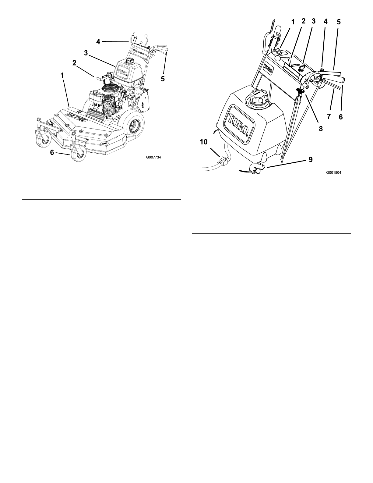
ProductOverview
Figure5
1.Mowerdeck
2.Brake5.Handle
3.Gastank6.Casterwheel
Controls
Becomefamiliarwithallthecontrols(Figure6)before
youstarttheengineandoperatethemachine.
4.Controls
Figure6
1.Throttlecontrol6.Handle
2.Speedcontrollever
3.Ignitionswitch
4.Neutrallock
5.OperatorPresence
Controllevers(OPC)
7.DriveLever
8.Bladecontrolknob(PTO)
9.Choke
10.Fuelshut-offvalve
ThrottleControl
Thethrottlecontrolhastwopositions:FastandSlow.
OperatorPresenceControl(OPC)
Levers
WhenyousqueezetheOPCleversagainstthehandles,
theOPCsystemsensesthattheoperatorisinthe
normaloperatingposition.WhenyoureleasetheOPC
levers,theOPCsystemsensesthattheoperatorhasleft
thenormaloperatingposition,andthesystemwillstop
theengineifeitherthespeedcontrolleverisnotinthe
neutralpositionorthebladecontrol(PTO)knobis
engaged.
BladeControlKnob(PTO)
Thebladecontrolknob(PTO)isusedtoengageand
disengagethedrivebelttodrivethemowerblades
withtheOPCleverspressedagainstthehandles.Pull
theknobuptoengagethebladesandpushdownto
disengagetheblades.
11
Page 12

IgnitionSwitch
48inchmowers:
Thisswitchisusedinconjunctionwithrecoilstarterand
hastwopositions:RunandOff.
SpeedControlLever
Thismachinehasavariablespeedcontrolwithaneutral
position.Thiscontrolshowfastthemachinewilltravel.
DriveLevers
Releasedriveleverstoengageforwardtractionoperation
andsqueezetheleversuntilanincreaseinforceisfelt
togointoneutralpositionandcontinuetosqueezeto
goinreverse.Squeezerighthanddrivelevertoturnright
andlefthandlevertoturnleft.
NeutralLock
Squeezedriveleversuntilanincreaseinforceisfeltand
movelockstotherearforneutrallock.
RecoilStarter
Width
Length
Height
Weight
49–1/2inches(126cm)
76–1/2inches(194cm)
44inches(1 12cm)
547lb(248kg)
Attachments/Acessories
AselectionofToroapprovedattachmentsand
accessoriesareavailableforusewiththemachineto
enhanceandexpanditscapabilities.Contactyour
AuthorizedServiceDealerorDistributorforalistofall
approvedattachmentsandaccessories.
Pulltherecoilstarterhandletostartengine(Figure5).
FuelShut-offValve
Closethefuelshut-offvalvewhentransportingor
storingmower.
Choke
Usethechoketostartacoldengine.
Specications
Note:Specicationsanddesignaresubjecttochange
withoutnotice.
32inchmowers:
Width
Length
Height
Weight
35inches(89cm)
80inches(203cm)
44inches(1 12cm)
509lb(231kg)
36inchmowers:
Width
Length
Height
Weight
37inches(94cm)
80inches(203cm)
44inches(1 12cm)
511lb(232kg)
12
Page 13

Operation
AddingFuel
UseUnleadedRegularGasolinesuitablefor
automotiveuse(85pumpoctaneminimum).
DANGER
Incertainconditions,gasolineisextremely
ammableandhighlyexplosive.Areorexplosion
fromgasolinecanburnyouandothersandcan
damageproperty.
•Fillthefueltankoutdoors,inanopenarea,
whentheengineiscold.Wipeupanygasoline
thatspills.
•Neverllthefueltankinsideanenclosedtrailer.
•Donotllthefueltankcompletelyfull.Add
gasolinetothefueltankuntilthelevelis1/4to
1/2inch(6to13mm)belowthebottomofthe
llerneck.Thisemptyspaceinthetankallows
gasolinetoexpand.
•Neversmokewhenhandlinggasoline,andstay
awayfromanopenameorwheregasoline
fumesmaybeignitedbyaspark.
DANGER
Incertainconditionsduringfueling,static
electricitycanbereleasedcausingasparkwhich
canignitethegasolinevapors.Areorexplosion
fromgasolinecanburnyouandothersandcan
damageproperty.
•Alwaysplacegasolinecontainersontheground
awayfromyourvehiclebeforelling.
•Donotllgasolinecontainersinsideavehicle
oronatruckortrailerbedbecauseinterior
carpetsorplastictruckbedlinersmayinsulate
thecontainerandslowthelossofanystatic
charge.
•Whenpractical,removegas-powered
equipmentfromthetruckortrailerandrefuel
theequipmentwithitswheelsontheground.
•Ifthisisnotpossible,thenrefuelsuch
equipmentonatruckortrailerfromaportable
container,ratherthanfromagasolinedispenser
nozzle.
•Ifagasolinedispensernozzlemustbeused,
keepthenozzleincontactwiththerimofthe
fueltankorcontaineropeningatalltimesuntil
fuelingiscomplete.
•Storegasolineinanapprovedcontainerand
keepitoutofthereachofchildren.Neverbuy
morethana30-daysupplyofgasoline.
•Donotoperatewithoutentireexhaustsystem
inplaceandinproperworkingcondition.
WARNING
Gasolineisharmfulorfatalifswallowed.
Long-termexposuretovaporscancauseserious
injuryandillness.
•Avoidprolongedbreathingofvapors.
•Keepfaceawayfromnozzleandgastankor
conditionerbottleopening.
•Avoidcontactwithskin;washoffspillagewith
soapandwater.
UsingStabilizer/Conditioner
Useafuelstabilizer/conditionerinthemachineto
providethefollowingbenets:
•Keepsgasolinefreshduringstorageof90daysor
less.Forlongerstorageitisrecommendedthatthe
fueltankbedrained.
•Cleanstheenginewhileitruns
•Eliminatesgum-likevarnishbuildupinthefuel
system,whichcauseshardstarting
Important:Donotusefueladditives
containingmethanolorethanol.
Addthecorrectamountofgas
stabilizer/conditionertothegas.
13
Page 14
Note:Afuelstabilizer/conditionerismost
effectivewhenmixedwithfreshgasoline.To
minimizethechanceofvarnishdepositsinthefuel
system,usefuelstabilizeratalltimes.
CAUTION
Childrenorbystandersmaybeinjuredifthey
moveorattempttooperatethemachinewhileit
isunattended.
FillingtheFuelTank
1.Shuttheengineoffandsettheparkingbrake.
2.Cleanaroundfueltankcapandremovethecap.
Addunleadedregulargasolinetofueltank,untilthe
levelis1/4to1/2inch(6to13mm)belowthe
bottomofthellerneck.Thisspaceinthetank
allowsgasolinetoexpand.Donotllthefueltank
completelyfull.
3.Installfueltankcapsecurely.Wipeupanygasoline
thatmayhavespilled.
ThinkSafetyFirst
Carefullyreadallthesafetyinstructionsanddecalsin
thesafetysection.Knowingthisinformationcould
helpyouoranybystandersavoidinjury.
Theuseofprotectiveequipmentforeyes,hearing,feet
andheadisrecommended.
CAUTION
Thismachineproducessoundlevelsinexcessof
85dBAattheoperator’searandcancausehearing
lossthroughextendedperiodsofexposure.
Alwaysremovetheignitionkeyandsettheparking
brakewhenleavingthemachineunattended,even
ifjustforafewminutes.
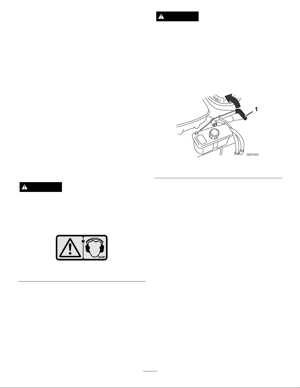
SettingtheParkingBrake
Pulltheparkingbrakeleverrearward(Figure8).
Figure8
1.Parkingbrakelever(inthereleasedposition)
ReleasingtheParkingBrake
Pushtheparkingbrakeleverforward.
Wearhearingprotectionwhenoperatingthis
machine.
Figure7
1.Warning—wearhearingprotection.
OperatingtheParkingBrake
Alwayssettheparkingbrakewhenyoustopthe
machineorleaveitunattended.Beforeeachuse,check
theparkingbrakeforproperoperation.
Iftheparkingbrakedoesnotholdsecurely,adjustit.
RefertoServicingtheParkingBrake.
StartingandStoppingthe
Engine
StartingtheEngine
1.Connectthewirestothesparkplugs.
2.Openthefuelvalve.
Note:Acoldweatherstaringkithasbeen
incorporatedtoassistenginestartingincold
weatherorwhentheunithasnotbeenrunfora
periodoftime.
Tousethecoldstartkit:
•Graspsplitring(Figure9)onrightsideof
machine,pullringandchainstraightoutfrom
sideofmachineandhookringovercontrol
shieldbolt.
14
Page 15
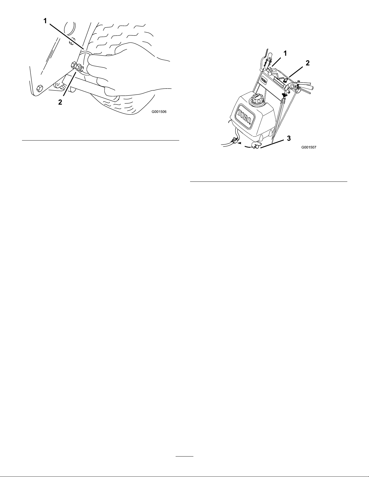
Figure9
1.Splitring2.Controlshieldbolt
4.Letengineidlefor30to60secondsbeforeturning
theengineoff.
5.Tostoptheengine,turntheignitionkeytooff.
•Aftertheengineisstarted,pullthechainstraight
outfromsideofmachineuntilringcanbe
removedfromshieldbolt.Slowlyreleasetension
onchain.
3.Disengagethebladecontrolknob(PTO)andmove
thespeedcontrollevertoneutral.
4.Movethedriveleverstoneutralandsettheneutral
locks.
5.Settheparkingbrake.
6.Turntheignitionkeytotherunposition(
Figure6).
7.Tostartacoldengine,movethethrottlecontrol
midwaybetweenthefastandslowpositions.
8.Tostartawarmengine,movethethrottlecontrol
tothefastposition.
9.Pullthechokeknobiftheengineiscold(
Figure6).
Note:Awarmorhotengineusuallydoesnot
requireanychoking.
10.Grasptherecoilstarterhandlermlyandpullit
outuntilpositiveengagementresults;thenpullthe
handlevigorouslytostarttheengine.Allowthe
ropetorecoilslowly.
Figure10
1.Throttlelever
2.Ignitionswitch
3.Choke
Important:Makesurefuelshutoffvalveis
closedbeforetransportingorstoringmachine,
asfuelleakagemayoccur.Beforestoring
machine,removewirefromthesparking
plug(s)topreventpossibilityofaccidental
starting.
OperatingtheNeutralLocks
Alwayssettheneutrallockwhenyoustopthemachine.
Settheparkingbrakeifitisleftunattended.
SettingtheNeutralLock
1.Squeezethedriveleversbackuntilanincreasein
forceisfelt.
2.Placethumbsontheupperpartofthelocksand
movethembackuntilthepinsareintheneutral
position(
Figure11).
11.Pushthechoketooffastheenginewarmsup
(Figure10).
12.Iftheengineiscold,allowittowarmupandthen
movethethrottlecontroltothefastposition.
StoppingtheEngine
1.Movedriveleverstoneutralandsetneutrallocks.
2.Movethethrottlelevertoslow(Figure10).
3.Disengagethebladecontrolknob(PTO)andmove
thespeedcontrollevertoneutral.
15
Page 16
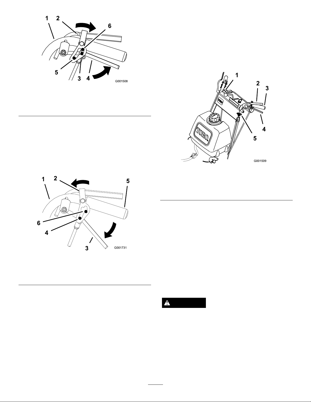
Figure11
1.Handle4.Drivelever
2.Neutrallock
3.Neutralposition6.Reverseposition
5.Fullspeedforward
ReleasingtheNeutralLock
1.Squeezethedriveleversbackuntilanincreasein
forceisfelt.
2.Placethumbsontheupperpartoflocksandmove
themforwarduntilthepinsareintheforwardslot
Figure12).
(
2.Pullbladecontrolknob(PTO)up.HoldtheOPC
leversagainsthandlegrip.
Note:ReleasingtheOPCleverswiththemower
bladesrunningwillkilltheengine.
3.Restarttheengineandrepeattheprocedureto
engagethemowerbladesiftheoperatorpresence
control(OPC)leversarereleased.
Figure13
1.Throttlelever4.DriveLever
2.OperatorPresence
Controllevers(OPC)
3.Handle
5.Bladecontrolknob(PTO)
Figure12
1.Handle
2.Neutrallock5.Handle
3.Drivelever6.Forwardslot
4.Pininfullspeedforward
OperatingtheMowerBlade
ControlKnob(PTO)
Thebladecontrolknob(PTO)isusedinconjunction
withtheOperatorPresenceControl(OPC)leversto
engageanddisengagethemowerblades.
EngagingtheMowerBlades(PTO)
1.Toengageblades,squeezetheOperatorPresence
Control(OPC)leversagainsthandlegrips
(Figure13).
DisengagingtheMowerBlades(PTO)
Themowerbladescanbedisengagedbyoneofthe
followingsteps.
1.Pushthebladecontrolknob(PTO)downtooff
(Figure13).
2.ReleasingtheOperatorPresenceControl(OPC)
leverswillkilltheengineandstoptheblades
Figure13)withthebladecontrolleverengaged.
(
TheSafetyInterlockSystem
CAUTION
Ifsafetyinterlockswitchesaredisconnectedor
damagedthemachinecouldoperateunexpectedly
causingpersonalinjury.
•Donottamperwiththeinterlockswitches.
•Checktheoperationoftheinterlockswitches
dailyandreplaceanydamagedswitchesbefore
operatingthemachine.
16
Page 17

UnderstandingtheSafetyInterlock
System
Thesafetyinterlocksystemisdesignedtopreventthe
mowerfromstartingunless:
•Thebladecontrolknob(PTO)ispushedoff.
•Thespeedcontrolleverisinneutral.
7.Withtheenginerunning,movethespeedcontrol
leverforward.ReleasetheOPClevers.Theengine
shouldkill.
8.Ifalltheaboveconditionsarenotmethavean
AuthorizedServiceDealerrepairthesafetysystem
immediately.
Thesafetyinterlocksystemisdesignedtokillthe
enginewhen:
•TheOperatorPresenceControl(OPC)leversare
releasedwiththemowerengagedand/orthespeed
controlisoutofneutral.
•Thespeedcontrolleverisshiftedoutofneutral
withoutholdingOPCleversorwiththebrake
engaged.
•Thebladecontrolknob(PTO)ispulledupwithout
holdingtheOPClevers.
TestingtheSafetyInterlockSystem
ServiceInterval:Beforeeachuseordaily
Testthesafetyinterlocksystembeforeyouusethe
machineeachtime.Ifthesafetysystemdoesnot
operateasdescribed,haveanAuthorizedService
Dealerrepairthesafetysystemimmediately.
WARNING
Whiletestingthesafetyinterlocksystem,the
machinemaymoveforwardandcausepersonal
injuryorpropertydamage.
DrivingtheMachineForward
andBackward
Thethrottlecontrolregulatestheenginespeedas
measuredinRPM(revolutionsperminute).Placethe
throttlecontrolinthefastpositionforbestmowing
performance.
DrivingForward
1.Releasetheparkingbrake.
2.Togoforward,movethespeedcontrolleverto
desiredspeed.
3.Releasetheneutrallock.RefertoReleasingthe
NeutralLock.
4.Slowlyreleasethedriveleverstomoveforward
Figure14).
(
Togostraight,releasedriveleversequally
(Figure14).
Toturn,squeezethedriveleveronthesideand
directionyouwanttoturn(
Figure14).
•Performthesafetyinterlocktestinanopen
area.
•Ensurenooneisstandinginfrontofthe
machinewhileperformingthesafetyinterlock
test.
1.Settheneutrallocksandplacespeedcontrollever
inneutral.
2.Starttheengine;refertoStartingandStoppingthe
Engine.
3.WithoutholdingtheOperatorPresenceControl
(OPC)levers,pullthebladecontrolknob(PTO)up.
Theengineshouldkill.
4.Pushthebladecontrolknobdowntooff.
5.Withenginerunning,holddowntheOPClevers.
Pullthebladecontrolknob(PTO)up.Thedrive
beltshouldengageandthemowerbladesbegin
rotating.
6.ReleasetheOPClevers.Theengineshouldkill.
Figure14
1.Drivelever
2.Speedcontrollever
DrivingBackward
Slowlysqueezethedriveleverstothehandletomove
rearward(Figure14).
17
Page 18

BringingtheMachineto
NeutralPosition
Alwayssettheneutrallockandparkingbrakewhenyou
stopthemachine.
1.Squeezethedriveleverstoneutralposition.
2.Settheneutrallocks.RefertoOperatingNeutral
Locks.
3.Movespeedcontrollevertoneutralposition.
StoppingtheMachine
1.Tostopthemachine,squeezethedriveleversto
neutralpositionandengageneutrallocks.
2.Movespeedcontrolleverintoneutral.
Note:Rotatetheby-passvalvesamaximumof2
turnssothevalvedoesnotcomeoutofthebody
causinguidtorunout.
Important:Donotstartoroperatethe
machinewiththeby-passvalvesopen.Damage
tosystemmayoccur.
3.Stoptheengine;refertoStoppingtheEngine.
4.Waitforallmovingpartstostopbeforeleavingthe
operatingposition.Settheparkingbrake.
CAUTION
Childrenorbystandersmaybeinjuredifthey
moveorattempttooperatethemachinewhileit
isunattended.
Alwaysremovetheignitionkeyandsettheparking
brakewhenleavingthemachineunattended,even
ifjustforafewminutes.
PushingtheMachinebyHand
Theby-passvalvesallowthemachinetobepushedby
handwithouttheenginerunning.
Important:Alwayspushthemachinebyhand.
Nevertowthemachinebecausehydraulicdamage
mayoccur.
ToPushtheMachine
1.DisengagethePTO,movethemotioncontrol
leverstotheneutrallockedpositionandsetthe
parkingbrake.
2.Opentheby-passvalvesbyturningthemcounter
clockwise1to2.Thisallowshydraulicuid
toby-passthepumpsandthewheelstoturn
(Figure15).
3.Releasetheparkingbrake.
4.Pushthemachinetothedesiredlocation.
5.Settheparkingbrake.
6.Closetheby-passvalves,butdonotovertighten
them.
Figure15
1.Hydraulicpump2.By-passvalve
TransportingMachines
Useaheavy-dutytrailerortrucktotransportthe
machine.Ensurethatthetrailerortruckhasall
necessarylightingandmarkingasrequiredbylaw .
Pleasecarefullyreadallthesafetyinstructions.
Knowingthisinformationcouldhelpyou,yourfamily,
petsorbystandersavoidinjury.
Totransportthemachine:
•Stoptheengine,removethekey,setthebrake,and
closethefuelvalve.
•Securelyfastenthemachinetothetrailerortruck
withstraps,chains,cable,orropes.
•Secureatrailertotowingvehiclewithsafetychains.
AdjustingtheHeight-of-Cut
Thismachinehasa1to4-1/4inch(26to108mm)
rangeforheight-of-cut.Thiscanbeachievedby
adjustingbladespacers,rearaxleheightandfrontcaster
spacers.UsetheHeight-of-Cutcharttoselectthe
combinationofadjustmentsrequired
AdjustingtheBladeHeight
AdjusttheBladesbyusingthe4spacers(1/4inch)
spacersonthebladespindlebolts.Thisallowsfora
1-inch(25mm)adjustmentrangeofcuttingheight,
in1/4inch(6mm)increments,inanyaxleposition.
Usethesamenumberofbladespacersonallbladesto
achievealevelcut(2aboveand2below ,1aboveand3
below,etc.).
18
Page 19

1.DisengagethePTOandpullthethrottletothe
slowposition.
2.Turntheignitionswitchtooff.
3.Waitforallmovingpartstostopbeforeleavingthe
operatingposition.Settheparkingbrake.
4.Holdthebladeboltandremovethenut.Slidethe
boltdownthroughthespindle,andchangethe
spacersasneeded(
Figure16).
3.Placeajackundertheengineframe.Raisetheback
endoftheengineframeupenoughtoremovethe
drivewheels.
4.Removethedrivewheels.
5.Loosen,butdonotremove,the2topaxlebolts
Figure17).
(
6.Removethe2loweraxlebolts(Figure17).
Figure16
1.Blade
2.Bladebolt5.Thinwasher
3.Curvedwasher
4.Spacer
6.Nut
5.Installthebolt,curvedwasher,blade,addextra
spacers,andsecurethemwithathinwasheranda
nut(Figure16).
6.Torquethebladeboltto75-80ft.-lb.(101-108N-m).
Figure17
1.Topaxlebolt2.Loweraxlebolt
7.Raiseorlowerthemountingbracket,sothatyou
caninstallthe2axleadjustmentboltsinthedesired
holelocation(Figure17).Ataperedpunchcanbe
usedtohelpaligntheholes.
8.Tightenall4bolts.
9.Installdrivewheelsandlowerthemower.
AdjustingtheCasterPosition
1.UsingtheHeight-of-CutChart,adjustthecaster
spacerstomatchwiththeaxleholeselected
Figure18).
(
AdjustingtheAxleHeight
Adjusttheaxlepositiontotheselectedheight-of-cut
setting.
1.DisengagethePTOandpullthethrottletothestop
position.
2.Waitforallmovingpartstostopbeforeleavingthe
operatingpositionandthensettheparkingbrake.
19
Page 20

Figure18
1.Latchpin
2.Spacer,3/16inch(5mm)
3.Spacer,1/2inch(13mm)
2.Removethelatchpin,slidethecasterfromthe
support,andchangethespacers(
Figure18).
3.Installthecasterinthesupportandinsertthelatch
pin(Figure18).
3.Removethelowerangebolts(3/8x1inch)
andangenutssecuringhandletorearframe
(Figure20).
4.Pivothandletodesiredoperatingpositionand
installlowerangebolts(3/8x1inch)andange
nutsintomountingholes.Tightenallangebolts.
AdjustingtheHandleHeight
Thehandlepositioncanbeadjustedtomatchthe
operator’sheightpreference.
1.Removethehairpincotterpinsandclevispinsfrom
thedriveleversandneutrallocks(
Figure19
1.Controlrod5.Lefthandleshown
2.Clevispin
3.Drivelever7.Hairpincotterpin
4.OperatorPresence
Controllever(OPC)
6.Neutrallock
Figure19).
Figure20
1.Controlrodtting
2.Lowermountingholes7.Lowerposition
3.Rearframe
4.Lowerangebolt(3/8x1
inch)
5.Upperangebolt(3/8x
1-1/4inches)
6.Highposition
8.Uppermountinghole
9.Handle
10.Flangenut(3/8inch)
5.Adjustthecontrolrodlengthbyrotatingthecontrol
rodintherodtting(Figure19andFigure20).
6.Installhairpincotterbetweendriveleversand
neutrallocksandintoclevispins(Figure19).
Note:Makesuretheclevispinsareinsertedinto
theneutrallocks.
7.Performthehydrauliclinkageadjustmentswhenthe
handleheightischanged;referHydraulicLinkage
Adjustments.
2.Loosentheupperangebolts(3/8x1-1/4inch)
andangenutsecuringhandletorearframe
(Figure20).
20
Page 21

HeightofCutChart
Numberofspacers
1/2inch
AxlePosition
A00
A01
A10
B01
B10
B11
B20
C
C
C
C
D21
D30
D31
D40
E31
E40
E41
(13mm)
11
20
21
30
belowcaster
3/16inch
(5mm)
Numberof1/4inch(6mm)bladespacersbelowspindle
43210
1inch(26
mm)
1–1/8inch
(29mm)
1–3/8inch
(35mm)
1–3/8inch
(35mm)
1–5/8inch
(41mm)
1–3/4inch
(45mm)
2inch(51
mm)
1–7/8inch
(48mm)
2–1/8inch
(54mm)
2–1/4inch
(57mm)
2–1/2inch
(64mm)
2–3/8inch
(60mm)
2–1/2inch
(64mm)
2–3/4inch
(70mm)
3inch(76
mm)
2–7/8inch
(73mm)
3–1/8inch
(79mm)
3–1/4inch
(83mm)
1–1/4inch
(32mm)
1–3/8inch
(35mm)
1–5/8inch
(41mm)
1–5/8inch
(41mm)
1–7/8inch
(48mm)
2inch(51
2–1/4inch
(57mm)
2–1/8inch
(54mm)
2–3/8inch
(60mm)
2–1/2inch
(64mm)
2–3/4inch
(70mm)
2–5/8inch
(67mm)
2–3/4inch
(70mm)
3inch(76
3–1/4inch
(83mm)
3–1/8inch
(79mm)
3–3/8inch
(86mm)
3–1/2inch
(89mm)
1–1/2inch
(38mm)
1–5/8inch
(41mm)
1–7/8inch
(48mm)
1–7/8inch
(48mm)
2–1/8inch
(54mm)
mm)
mm)
2–1/4inch
(57mm)
2–1/2inch
(64mm)
2–3/8inch
(60mm)
2–5/8inch
(67mm)
2–3/4inch
(70mm)
3inch(76
mm)
2–7/8inch
(73mm)
3inch(76
mm)
3–1/4inch
(83mm)
3–1/2inch
(89mm)
3–3/8inch
(86mm)
3–5/8inch
(92mm)
3–3/4inch
(95mm)
1–3/4inch
(45mm)
1–7/8inch
(48mm)
2–1/8inch
(54mm)
2–1/8inch
(54mm)
2–3/8inch
(60mm)
2–1/2inch
(64mm)
2–3/4inch
(70mm)
2–5/8inch
(67mm)
2–7/8inch
(73mm)
3inch(76
mm)
3–1/4inch
(83mm)
3–1/8inch
(79mm)
3–1/4inch
(83mm)
3–1/2inch
(89mm)
3–3/4inch
(95mm)
3–5/8inch
(92mm)
3–7/8inch
(98mm)
4inch(102
mm)
2inch(51
mm)
2–1/8inch
(54mm)
2–3/8inch
(60mm)
2–3/8inch
(60mm)
2–5/8inch
(67mm)
2–3/4inch
(70mm)
3inch(76
mm)
2–7/8inch
(73mm)
3–1/8inch
(79mm)
3–1/4inch
(83mm)
3–1/2inch
(89mm)
3–3/8inch
(86mm)
3–1/2inch
(89mm)
3–3/4inch
(95mm)
4inch(102
mm)
3–7/8inch
(98mm)
4–1/8inch
(105mm)
4–1/4inch
(108mm)
21
Page 22

Maintenance
Note:Determinetheleftandrightsidesofthemachinefromthenormaloperatingposition.
RecommendedMaintenanceSchedule(s)
MaintenanceService
Interval
Aftertherst8hours
Aftertherst25hours
Beforeeachuseordaily
Every25hours
Every50hours
Every100hours
MaintenanceProcedure
•Changetheengineoil.
•Checkthemowerbelttension.
•Checkthehydraulicuidlevel.
•Replacethehydraulicoillter.
•Checkthemowerbelttension.
•Checkthesafetysystem.
•Greasethecasterwheelsandcasterpivot.
•Checktheengineoillevel.
•Cleantheairintakescreen.
•Inspecttheblades.
•Cleanthemowerdeck.
•Cleanfoamaircleanerelement.
•Checkthehydraulicuidlevel.
•Greasethemowerbeltidler.
•Greasethepumpdriveidlerpivot.
•Greasethepumpcontrol.
•Checkthepaperaircleanerelement.
•Checkthetyrepressure.
•Checkthebelts.
•Checkthemowerbelttension.
•Greasethebladeengagementbellcrank.
•Changetheengineoil.
•Checkthesparkplugs.
•Checkandcleanenginecoolingnsandshrouds.
•Checkhydrauliclinesandhoses.
•Replacethepaperaircleanerelement.
Every200hours
Every400hours
Beforestorage
•Replacetheengineoillter
•Replacethefuellter.
•Replacethehydraulicoillter.
•LubricatethecamlockwithNever-Seez®.
•Paintchippedsurfaces.
•Performallmaintenanceprocedureslistedabovebeforestorage.
Important:Refertoyourengineoperator’smanualforadditionalmaintenanceprocedures.
CAUTION
Ifyouleavethekeyintheignitionswitch,someonecouldaccidentlystarttheengineandseriouslyinjure
youorotherbystanders.
Removethekeyfromtheignitionanddisconnectthesparkplugwirefromthesparkplug(s)beforeyoudo
anymaintenance.Setthewireasidesothatitdoesnotaccidentallycontactthesparkplug.
Lubrication
UseFigure21forlocatingthegreasepointsonthe
machine.
GreasewithNo.2generalpurposelithiumbaseor
molybdenumbasegrease.
22
Page 23

HowtoGrease
1.DisengagethePTOandsettheparkingbrake.
2.Stoptheengine,removethekey,andwaitforall
movingpartstostopbeforeleavingtheoperating
position.
3.Cleanthegreasettingswitharag.Makesureto
scrapeanypaintoffthefrontofthetting(s).
4.Connectagreaseguntothetting.Pumpgrease
intothettingsuntilgreasebeginstooozeoutof
thebearings.
5.Wipeupanyexcessgrease.
LubricatingtheCasterand
WheelBearings
ServiceInterval:Beforeeachuseordaily
Lubricatethefrontwheelbearingsandfrontspindles
Figure21).
(
GreasingtheMowerBeltIdler
ServiceInterval:Every50hours
Greasethettingonthemowerbeltidlerarmpivot
Figure21).
(
Note:Removethemowerdeckcovertoaccessthe
greasettingforthemowerbeltidlerarm.
GreasingthePumpControl
andBellCrank
ServiceInterval:Every50hours—Greasethepump
driveidlerpivot.
Figure21
1.Pumpdriveidlerarm4.Mowerbeltidlerarm
2.Pumpcontrolarm
3.Bellcrank
5.Casterwheelbearing
6.Casterpivot
Every50hours—Greasethepump
control.
Every100hours—Greasetheblade
engagementbellcrank.
Every400hours—Lubricatethecam
lockwithNever-Seez
Greasethettingonthepumpdriveidlerpivotandthe
pumpcontrol.
Greasethebladeengagement(PTO)bellcrank
(Figure21).
LubricatecamlockwithNever-Seez
lubricant.
Note:Removetheguardsttedunderthemachineto
accessthegreasettingonthepumpdriveidlerpivot.
®
.
®
orequivalent
23
Page 24

EngineMaintenance
ServicingtheAirCleaner
ServiceInterval/Specication
Note:Servicetheaircleanermorefrequently(every
fewoperatinghours)iftheoperatingconditionsare
extremelydustyorsandy.
Important:Donotoilthefoamorpaperelement.
RemovingtheFoamandPaper
Elements
1.DisengagethePTOandsettheparkingbrake.
2.Stoptheengine,removethekey,andwaitforall
movingpartstostopbeforeleavingtheoperating
position.
3.Cleanaroundtheaircleanertopreventdirt
fromgettingintotheengineandcausingdamage
Figure22).
(
4.Unscrewthecoverknobandremovetheaircleaner
cover(Figure22).
5.Removethe2wingnutsandremovetheaircleaner
assembly(Figure22).
Figure22
1.Engine4.Foamelement
2.Cover
3.Wingnut
5.Paperelement
6.Coverknob
6.Carefullypullthefoamelementoffthepaper
element(
Figure22).
CleaningtheFoamAirCleanerElement
ServiceInterval:Every25hours
1.Washthefoamelementinliquidsoapandwarm
water.Whentheelementisclean,rinseitthoroughly.
2.Drytheelementbysqueezingitinacleancloth.
Important:Replacethefoamelementifitis
tornorworn.
ServicingthePaperAirCleaner
Element
ServiceInterval:Every50hours
Every200hours
1.Donotcleanthepaperlter,replaceit(Figure22).
2.Inspecttheelementfortears,anoilylm,ordamage
totherubberseal.
3.Replacethepaperelementifitisdamaged.
InstallingtheFoamandPaperElements
Important:Topreventenginedamage,always
operatetheenginewiththecompletefoamand
paperaircleanerassemblyinstalled.
24
Page 25

1.Carefullyslidethefoamelementontothepaperair
cleanerelement(Figure22).
2.Placetheaircleanerassemblyontotheaircleaner
baseandsecureitwiththe2wingnuts(
Figure22).
3.Placetheaircleanercoverintopositionandtighten
thecoverknob(Figure22).
ServicingtheEngineOil
ServiceInterval/Specication
Note:Changetheoilmorefrequentlywhenthe
operatingconditionsareextremelydustyorsandy .
OilType:Detergentoil(APIserviceSF ,SG,SH,orSJ)
CrankcaseCapacity:58ounces(1.7liter)withthelter
removed;51ounces(1.5liter)withoutthelterremoved
Viscosity:Refertothetable(Figure23).
Figure24
1.Oildipstick
2.Fillertube
5.Unscrewtheoildipstickandwipetheendclean
(Figure24).
6.Slidetheoildipstickfullyintothellertube,butdo
notthreadontotube(Figure24).
7.Pullthedipstickoutandlookattheend.Iftheoil
levelislow ,slowlypouronlyenoughoilintotheller
tubetoraisetheleveltotheFullmark.
Figure23
CheckingtheEngineOilLevel
ServiceInterval:Beforeeachuseordaily
1.Parkthemachineonalevelsurface.
2.DisengagethePTOandsettheparkingbrake.
3.Stoptheengine,removethekey,andwaitforall
movingpartstostopbeforeleavingtheoperating
position.
Important:Donotoverllthecrankcasewith
oilandruntheengine;enginedamagecan
result.
ChangingtheOil
ServiceInterval:Aftertherst8hours
Every100hours
1.Starttheengineandletitrunveminutes.This
warmstheoilsoitdrainsbetter.
2.Parkthemachinesothatthedrainsideisslightly
lowerthantheoppositesidetoassuretheoildrains
completely.
3.DisengagethePTOandsettheparkingbrake.
4.Stoptheengine,removethekey,andwaitforall
movingpartstostopbeforeleavingtheoperating
position.
5.Slidethedrainhoseovertheoildrainvalve.
6.Placeapanbelowthedrainhose.Rotateoildrain
valvetoallowoiltodrain(
Figure25).
4.Cleanaroundtheoildipstick(Figure24)sothatdirt
cannotfallintothellerholeanddamagetheengine.
7.Whenoilhasdrainedcompletely,closethedrain
valve.
8.Removethedrainhose(Figure25).
Note:Disposeoftheusedoilatarecyclingcenter.
25
Page 26

3.Applyathincoatofnewoiltotherubbergasketon
1
thereplacementlter(Figure26).
4.Installthereplacementoilltertothelteradapter,
turntheoillterclockwiseuntiltherubbergasket
contactsthelteradapter,thentightenthelteran
additional3/4turn(
Figure26).
5.Fillthecrankcasewiththepropertypeofnewoil;
refertoServicingtheEngineOil.
6.Runtheengineforabout3minutes,stoptheengine,
andcheckforoilleaksaroundtheoillteranddrain
valve.
7.Checktheengineoillevelandaddoilifneeded.
ServicingtheSparkPlugs
Figure25
1.Oildrainvalve2.Oildrainhose
9.Slowlypourapproximately80%ofthespeciedoil
intothellertube(Figure24).
10.Checktheoillevel;refertoCheckingtheEngineOil
Level.
11.SlowlyaddtheadditionaloiltobringittotheFull
mark.
ChangingtheOilFilter
ServiceInterval:Every200hoursoreveryotheroil
change.
Note:Changetheoilltermorefrequentlywhenthe
operatingconditionsareextremelydustyorsandy .
1.Draintheoilfromtheengine;refertoChangingthe
EngineOil.
2.Removetheoldlter(
Figure26).
ServiceInterval/Specication
Ensurethattheairgapbetweenthecenterandside
electrodesiscorrectbeforeinstallingthesparkplug.
Useasparkplugwrenchforremovingandinstallingthe
sparkplugsandagappingtool/feelergaugetocheckand
adjusttheairgap.Installanewsparkplugsifnecessary .
Type:Champion®RCJ8YorequivalentAirGap:
0.030inch(0.75mm)
RemovingtheSparkPlugs
1.DisengagethePTOandsettheparkingbrake.
2.Stoptheengine,removethekey,andwaitforall
movingpartstostopbeforeleavingtheoperating
position.
3.Disconnectthewiresfromthesparkplugs
Figure27).
(
1.Oillter
Figure26
Figure27
2.Adapter
1.Spark-plugwire/sparkplug
26
Page 27

4.Cleanaroundthesparkplugstopreventdirtfrom
fallingintotheengineandpotentiallycausing
damage.
5.Removethesparkplugsandthemetalwashers.
CheckingtheSparkPlugs
FuelSystem
Maintenance
ServicingtheFuelTank
ServiceInterval:Every100hours
1.Lookatthecenterofthesparkplugs(Figure28).
Ifyouseelightbrownorgrayontheinsulator,the
engineisoperatingproperly .Ablackcoatingonthe
insulatorusuallymeansthattheaircleanerisdirty.
2.Ifneeded,cleanthesparkplugwithawirebrushto
removecarbondeposits.
Figure28
1.Centerelectrodeinsulator3.Airgap(nottoscale)
2.Sideelectrode
Important:Alwaysreplacethesparkplugs
whenithasablackcoating,wornelectrodes,
anoilylm,orcracks.
3.Checkthegapbetweenthecenterandsideelectrodes
Figure28).Bendthesideelectrode(Figure28)if
(
thegapisnotcorrect.
DANGER
Incertainconditions,gasolineisextremely
ammableandhighlyexplosive.Areorexplosion
fromgasolinecanburnyouandothersandcan
damageproperty.
•Draingasolinefromthefueltankwhenthe
engineiscold.Dothisoutdoorsinanopenarea.
Wipeupanygasolinethatspills.
•Neversmokewhendraininggasoline,andstay
awayfromanopenameorwhereasparkmay
ignitethegasolinefumes.
DrainingtheFuelTank
1.Parkthemachineonalevelsurface,toassurefuel
tankdrainscompletely.Thendisengagethepower
takeoff(PTO),settheparkingbrake,andturnthe
ignitionkeytooff.Removethekey.
2.Closethefuelshut-offvalveatthefueltank
Figure29).
(
3.Squeezetheendsofthehoseclamptogether
andslideitupthefuellineawayfromfuellter
(Figure29).
4.Pullthefuellineoffthefuellter(Figure29).Open
thefuelshut-offvalveandallowthegasolinetodrain
intoagascanordrainpan.
Note:Nowisthebesttimetoinstallanewfuellter
becausethefueltankisempty.RefertoReplacing
theFuelFilter.
InstallingtheSparkPlugs
1.Installthesparkplugsandthemetalwasher.Ensure
thattheairgapissetcorrectly .
2.Tightenthesparkplugsto16ft-lb(22N-m).
3.Connectthewirestothesparkplugs(Figure28).
5.Installthefuellineontothefuellter.Slidethehose
clampclosetothevalvetosecurethefuelline.
27
Page 28

Figure29
1.Fuelshut-offvalve2.Fuellter
ServicingtheFuelFilter
Figure30
1.Hoseclamp3.Filter
2.Fuelline
ReplacingtheFuelFilter
ServiceInterval:Every200hours/Y early(whichever
comesrst)
Neverinstalladirtylterifitisremovedfromthefuel
line.
Note:Notehowthefuellterisinstalledinorderto
installthenewltercorrectly.
Note:Wipeupanyspilledfuel.
1.DisengagethePTOandsettheparkingbrake.
2.Stoptheengine,removethekey,andwaitforall
movingpartstostopbeforeleavingtheoperating
position.
3.Closefuelshut-offvalveatthefueltank(
4.Squeezetheendsofthehoseclampstogetherand
slidethemawayfromthelter(Figure30).
Figure29).
5.Removethelterfromthefuellines.
6.Installanewlterandmovethehoseclampsclose
tothelter.
7.Openfuelshut-offvalveatfueltank(
Figure29).
8.Checkforfuelleaksandrepairifneeded.
9.Wipeupanyspilledfuel.
28
Page 29

DriveSystem
Maintenance
Performthefollowinglinkageadjustmentswhenthe
machineneedsmaintenance.PerformstepsAdjustthe
SpeedControlLinkagethroughAdjustingtheTracking.
Ifanyadjustmentisneeded,dothemintheorderthat
theyarelisted.
AdjustingtheSpeedControl
Linkage
1.DisengagethePTOandsettheparkingbrake.
2.Stoptheengineandwaitforallmovingpartstostop
beforeleavingtheoperatingposition.
3.Movethespeedcontrollever(locatedonthe
console)tothefullforwardposition.
4.Checktheorientationofthetabsontheendsofthe
speedcontrolcrank.Thesetabsshouldbepointing
straightdownatthe6o’clockpositionapproximately
Figure31).
(
7.Checktomakesurethesafetyswitchisdepressed
andthereisa5/16inch(8mm)spacebetweenthe
actuatingtabandtheswitch.(Figure32).
8.Ifneeded,adjustswitchlocationtocreatethe
5/16inch(8mm)space(Figure32).
5.Adjustthethreadedyokeatthebottomofthespeed
controllinkageuntilthetabsareatthe6o’clock
position(
1.Speedcontrolrod
2.Yoke5.Jamnut
3.Speedcontrolcrank
6.Pullthespeedcontrolleverbacktoneutral.
Figure31).
Figure31
4.Tabs,6o’clockposition
Figure32
1.Safetyswitch
2.5/16inch(8mm)space
3.Actuatingtab
AdjustingtheNeutralControl
Linkages
WARNING
Enginemustberunningsocontrollinkage
adjustmentscanbeperformed.Contactwith
movingpartsorhotsurfacesmaycausepersonal
injury.
Keephands,feet,face,clothingandotherbody
partsawayfromrotatingparts,muferandother
hotsurfaces.
WARNING
Mechanicalorhydraulicjacksmayfailtosupport
machineandcauseaseriousinjury .
•Usejackstandswhensupportingmachine.
•Donotusehydraulicjacks.
29
Page 30

1.DisengagethePTOandsettheparkingbrake.
2.Stoptheengineandwaitforallmovingpartstostop
beforeleavingtheoperatingposition.
3.Raisetherearofthemachineontojackstandsto
raisethedrivewheelsofftheground.
4.Disengagetheparkingbrake.
5.Starttheengineandmovethethrottleaheadtothe
fullthrottleposition.
6.Placetheneutrallocksinthefullforwardposition
andmovethespeedcontrollevertothemedium
speedposition.
7.HoldOPCleversdown.
Note:TheOPCleversmustbehelddown
wheneverthespeedcontrolleverisoutoftheneutral
positionortheenginewillkill.
WARNING
Electricalsystemwillnotperformpropersafety
shutoffwithOperatorPresenceControl(OPC)
levershelddowninplace.
•MakesureOperatorPresenceControl(OPC)
leversareworkingwhenadjustmentis
completed.
•NeveroperatethisunitwithOperator
PresenceControl(OPC)levershelddownin
place.
14.Afteradjustmentsaremade,tightenthenutsagainst
theyokes.
15.Repeatthisprocedurefortheoppositeside.
Figure33
1.Neutralcontrollinkage3.Adjustingbolt
2.Yoke4.Nut
AdjustingtheHydroControl
Linkages
8.Squeezeonedriveleveruntilanincreasedresistance
isfelt.Thisiswhereneutralshouldbe.
Note:Makesureyouhavenotreachedtheendof
theneutrallockslot.Ifyouhave,shortenthecontrol
leverlinkage.RefertoAdjustingtheControlRod.
9.Ifthewheelturnswhileholdingthedrivelever
inneutral,theneutralcontrollinkagesneedtobe
adjusted(
12.
10.Loosenthenutagainsttheneutralcontrollinkage
yoke(
11.Adjusttheneutralcontrollinkageuntilthe
respectivedrivewheelstopswhilethedriveleveris
pulledagainsttheneutralspring(neutralposition)
(
Figure33).
12.Turntheadjustingboltapproximately1/4turn
clockwiseifthewheelisturninginreverseorturn
theboltapproximately1/4turncounter-clockwiseif
thewheelisturningforward(Figure33).
13.Releasethedrivelevertotheforwarddriveposition
andsqueezebackintotheneutralposition.Check
toseeifthewheelstops.Ifnot,repeattheabove
adjustmentprocedure.
Figure33).Ifwheelstopsthengotostep
Figure33).
WARNING
Enginemustberunningsocontrollinkage
adjustmentscanbeperformed.Contactwith
movingpartsorhotsurfacesmaycausepersonal
injury.
Keephands,feet,face,clothingandotherbody
partsawayfromrotatingparts,muferandother
hotsurfaces.
WARNING
Mechanicalorhydraulicjacksmayfailtosupport
machineandcauseaseriousinjury .
•Usejackstandswhensupportingmachine.
•Donotusehydraulicjacks.
AdjustingtheLeftSideLinkage
1.DisengagethePTOandsettheparkingbrake.
2.Stoptheengineandwaitforallmovingpartstostop
beforeleavingtheoperatingposition.
3.Raisetherearofthemachineontojackstandshigh
enoughtoraisethedrivewheelsoffoftheground.
30
Page 31

4.Disengagetheparkingbrake.
5.Starttheengineandmovethethrottleaheadtothe
fullthrottleposition.
6.Placetheleftdriveleverinthefullforwardposition.
12.Afteradjustingthelefthydrocontrollinkage,move
thespeedcontrolleverforwardandthenbacktothe
neutralposition.
13.HoldtheOPCleversdown.
7.Placethespeedcontrolleverintheneutralposition.
WARNING
Electricalsystemwillnotperformpropersafety
shutoffwithOperatorPresenceControl(OPC)
leversheldinplace.
•MakesureOperatorPresenceControl(OPC)
leversareworkingwhenadjustmentis
completed.
•NeveroperatethisunitwithOperator
PresenceControl(OPC)leversheldinplace.
8.Loosenthefrontadjustingnutonlefthydrocontrol
linkageasshowninFigure35.
9.Turntheleftrearadjustingnutcounter-clockwise
untilwheelrotatesforward(
10.Turntherearadjustingnutclockwise1/4ofaturnat
atime.Thenmovethespeedcontrolleverforward
andbacktoneutral.Repeatthisuntilleftwheelstops
rotatingforward(
Figure35).
11.Turntherearnutanadditional1/2turnandtighten
thefrontadjustingnut.
Figure35).
Note:TheOPCleversmustbehelddown
wheneverthespeedcontrolleverisoutoftheneutral
positionortheenginewillkill.
14.Makesurethespeedcontrolleverisintheneutral
positionandthetyredoesnotrotate.
15.Repeattheadjustmentifneeded.
Note:Makesureatpartoflinkageisperpendicular
topinpartofswivel(
1.Hydrauliccontrollinkage
2.Swivelwithpin4.Correctpositionfor
Figure34).
Figure34
3.Incorrectpositionfor
hydrauliccontrollinkage
Hydrauliccontrollinkage,
90degrees
Figure35
1.Hydrocontrollinkage3.Rearadjustingnut
2.Frontadjustingnut
4.Controlarm
Note:Ifinconsistentneutraloccurs,checktobe
surebothspringsareproperlytightenedonthespeed
controlleverundertheconsole,especiallytherear
pivotspring.Repeataboveadjustmentsifnecessary
Figure36).
(
Figure36
1.Speedcontrollever
2.Rearpivotspring
3.spring
31
Page 32

AdjustingtheRightSideLinkage
1.Placethespeedcontrolleverintheneutralposition.
2.Placetherightdriveleverinthefullforwardposition.
3.Adjusttherightsidelinkagebyturningthequick
trackknobcounterclockwiseuntilthetyrebeginsto
rotateforward(Figure37).
4.Turntheknobclockwise1/4ofaturnatatime.
Thenmovethespeedcontrolforwardandbackto
neutral.Repeatthisuntilrightwheelstopsrotating
forward(
5.HoldtheOPCleversdown.
Note:TheOPCleversmustbehelddown
wheneverthespeedcontrolleverisoutoftheneutral
positionortheenginewillkill.
6.Thespringthatkeepstensionontheknobshould
normallynotneedadjustment.Howeverifan
adjustmentisneeded,adjustthelengthofspringto
1inch(26mm)betweenthewashers(
7.Adjustspringlengthbyturningnutatfrontofspring
Figure37).
(
Figure37).
Figure37).
Note:TheOPCleversmustbehelddown
wheneverthespeedcontrolleverisoutoftheneutral
positionortheenginewillkill.
2.Movetherespectivedriveleverupwarduntilit
reachestheneutralpositionandengageneutrallocks.
3.Ifthetyrerotatesineitherdirection,thelengthof
thecontrolrodwillneedtobeadjusted.
AdjustingtheControlRod
1.Adjusttherodlengthbyreleasingthedrivelever
andremovingthehairpincotterpinandclevispin.
Rotatetherodintherodtting(
2.Lengthenthecontrolrodifthetyreisturningin
reverseandshortentherodifthetyreisturning
forward.
3.Rotatetherodseveralturnsifthetyreisrotatingfast.
Then,adjusttherodin1/2turnincrements.
4.Placetheclevispinintothedrivelever(
Figure38).
Figure38).
Figure37
1.Hydrocontrollinkage
2.Spring4.1inch(26mm)
3.Quicktrackknob
AdjustingtheControlRod
CheckingtheControlRod
1.Withrearofmachinestillonjackstandsandengine
runningatfullthrottle,movethespeedcontrollever
tothemediumspeedposition.
Figure38
1.Controlrod5.Lefthandleshown
2.Clevispin
3.Drivelever7.Hairpincotterpin
4.OperatorPresence
Controllever(OPC)
6.Neutrallock
5.Releaseandengageneutrallockcheckingthatthe
tyredoesnotrotate(Figure39).Continuethis
processuntilthetyredoesnotrotate.
6.Installthehairpincotterpinbetweenthedrive
leversandtheneutrallocksandintotheclevispins
(
Figure38).
7.Repeatthisadjustmentfortheoppositeside.
32
Page 33

Figure39
1.Handle5.Neutralposition
2.Neutrallock6.Drivelever
3.Handle
4.Neutrallockslot
7.Fullspeedforward
8.Controlrod
AdjustingtheTracking
1.Removemachinefromanyjackstands.
2.Stoptheengineandwaitforallmovingpartstostop
beforeleavingtheoperatingposition.
3.Foraheavierdrivesetting,relocatethespringanchor
linkstoeitherthemediumorheavydutypositions
Figure41).Thespringanchorlinksareattachedto
(
theupperrearcornerofthehydrodriveshieldson
theleftandrightsidesofthemachine.
Note:Inthemediumorheavydutypositions,the
driveleverforcesattheupperhandlewillalsobe
increased
2.Checkthereartyrepressure.RefertoCheckingthe
tyrePressure.
3.Runtheunitandobservethetrackingonalevel,
smooth,hardsurfacesuchasconcreteorasphalt.
4.Iftheunittrackstoonesideortheother,turnthe
quicktrackknob.Turntheknobrighttosteerright
andturntheknoblefttosteerleft(
Figure40
1.Quicktrackknob
Figure40).
Figure41
1.Springanchor
2.Standardsetting
3.Mediumsetting
4.Heavydutysetting
CheckingtheTyrePressure
ServiceInterval:Every50hours/Monthly(whichever
comesrst)
Maintaintheairpressureinthereartyresasspecied.
Checkthepressureatthevalvestem(Figure42).
RearTyrePressure:15psi(1bar)
AdjustingtheSpringAnchor
Links
Formediumorheavydutydriveconditions,suchas
operatingwithasulkyonsteepslopes,ahigherspring
forcemayberequiredonthehydropumpcontrolarms
topreventthedrivesystemfromstalling.
1.DisengagethePTOandsettheparkingbrake.
Figure42
33
Page 34

CoolingSystem
BrakeMaintenance
Maintenance
CleaningtheAirIntakeScreen
ServiceInterval:Beforeeachuseordaily
Beforeeachuseremoveanybuild-upofgrass,dirt
orotherdebrisfromthecylinderandcylinderhead
coolingns,airintakescreenonywheelend,and
carburetor-governorleversandlinkage.Thiswillhelp
insureadequatecoolingandcorrectenginespeedand
willreducethepossibilityofoverheatingandmechanical
damagetotheengine.
CleaningtheCoolingSystem
ServiceInterval:Every100hours/Y early(whichever
comesrst)
1.DisengagethePTOandsettheparkingbrake.
2.Stoptheengine,removethekey,andwaitforall
movingpartstostopbeforeleavingtheoperating
position.
3.Removetheairintakescreen,recoilstarterandfan
housing(
4.Cleanthedebrisandgrassfromtheengineparts.
5.Installairintakescreen,recoilstarterandfanhousing
(Figure43).
Figure43).
ServicingtheBrake
Beforeeachuse,checktheparkingbrakeforproper
operation.
Alwayssettheparkingbrakewhenyoustopthemachine
orleaveitunattended.Iftheparkingbrakedoesnot
holdsecurely,adjustit.
CheckingtheParkingBrake
1.Movethemachineontoalevelsurface.
2.Disengagethepowertakeoff(PTO)andstopthe
engine.
3.Settheparkingbrake.
Note:Settingtheparkingbrakeshouldtakea
reasonableamountofforce.Ifitengagestoohard
ortooeasily,anadjustmentisrequired.Referto
AdjustingtheParkingBrake.
AdjustingtheParkingBrake
Theparkingbrakeleverisontherightsideofthe
machine.Iftheparkingbrakedoesnotholdsecurely,
adjustit.
1.Checktheparkingbrakebeforeyouadjustit;referto
CheckingtheParkingBrake.
2.Releasetheparkingbrake;refertoReleasingthe
ParkingBrake.
3.Removethespringhairpinfromthelowerbrake
link(Figure44).
Figure43
1.Airintakescreen4.Bolt
2.Fanhousing5.Nut
3.Recoilstarter
Figure44
1.Brakelinkageyoke4.Lowerbrakelink
2.Lowerbrakelever
3.Springclevispin
4.Rotatethelowerbrakelinkyokeclockwiseintothe
yoketotightentheparkingbrake;rotatethebrake
34
5.1/4inch(6mm)
6.Hairpin
Page 35

linkyokecounterclockwiseoutoftheyokeoutto
loosentheparkingbrake(Figure44).
BeltMaintenance
Note:Thereshouldbeapproximately1/4inch
clearancebetweenthetyreandtheatbarwhenthe
parkingbrakeinthereleasedposition(
5.Securethelowerlinktothelowerbrakeleverwith
thehairpincotterandtheclevispin(Figure44).
6.Checkthebrakeoperationagain;refertoChecking
theParkingBrake.
Figure44).
CheckingtheBelts
ServiceInterval:Every50hours/Monthly(whichever
comesrst)
Checkthebeltsforsquealingwhenthebeltisrotating,
bladesslippingwhencuttinggrass,frayedbeltedges,
burnmarksandcracksaresignsofawornmowerbelt.
Replacethemowerbeltifanyoftheseconditionsare
evident.
ReplacingtheMowerBelt
1.Disengagethebladecontrol(PTO)leverandsetthe
parkingbrakes.
2.Stoptheengineandwaitforallmovingpartstostop
beforeleavingtheoperatingposition.
3.Removetheknobsandthebeltcoveronthemower.
4.Removetheidlerpulleyandthewornbelt(
5.Installthenewmowerbelt.
Figure45).
6.Installtheidlerpulley.
7.Engagethebladecontrol(PTO)leverandcheck
thebelttension.RefertoAdjustingtheMowerBelt
Tension.
Note:Thepropermowerbelttensionis10-15lbf.
(44-67N)withthebeltdeected1/2inch(13mm)
halfwaybetweenthepulleys(
Figure45).
Figure45
1.Idlerpulley
35
2.Mowerbeltwith1/2inch
(13mm)deection
Page 36

AdjustingtheMowerBelt
Tension
AdjustingtheTension
ServiceInterval:Aftertherst8hours
Aftertherst25hours
Every50hours
Important:Thebrakeneedstobeadjustedwhen
thebelttensionorthebrakelinkageisadjusted.
Important:Thebeltmustbetightenoughtonot
slipduringheavyloadswhilecuttinggrass.Over
tensioningthebeltwillreducethespindlebearing
life,thebeltlifeandtheidlerpulleylife.
Thebeltmustbetightenoughsoitdoesnotslipduring
heavyloadswhilecuttinggrassandover-tensioningwill
reducebeltandspindlebearinglife.
1.Disengagethebladecontrol(PTO)leverandsetthe
parkingbrakes.
5.Engagethebladecontrollever(PTO)andcheckthe
belttension.
6.Ifthereisnoadjustmentleftintheturnbuckleand
thebeltisstillloose,therearidlerpulleyneedstobe
positionedtothemiddleorfronthole(
Figure47).
Usetheholethatwillgivethecorrectadjustment.
7.Whentheidlerpulleyismovedthebeltguidemust
bemoved.Movethebeltguidetothefrontposition
Figure47).
(
2.Stoptheengineandwaitforallmovingpartstostop
beforeleavingtheoperatingposition.
3.Loosenthelocknutontheturnbuckle(
Figure46).
4.Rotatetheturnbuckletowardtherearofthe
mowertoincreasethetensiononthebelt.Rotate
theturnbuckletowardthefrontofthemowerto
decreasethetensiononthebelt(
Figure46).
Note:Theeyeboltthreadsonbothendsofthe
turnbuckleshouldbeengagedaminimumof
5/16inch(8mm).
Figure47
1.Rearidlerpulley4.Beltguideinbackposition
2.Middlehole
3.Fronthole
5.Frontidlerpulley(48inch
mowerdeckonly)
8.Checkthebeltguideundertheengineframefor
properadjustment(Figure48).
Note:Thedistancebetweenthebeltguideand
themowerbeltshouldbe3/4inch(19mm)when
youengagethemowerbelt(Figure48).Adjustthe
mowerbeltguideasnecessary.Thedisengagedbelt
shouldnotdragorfalloffthepulleywhentheguides
areproperlyadjusted.
Figure46
1.Locknut4.Assistarm
2.Turnbuckle
3.Frontstop
5.1/2inch(13mm)deection
here
36
Page 37

Figure48
1.Beltguide
9.Checkthebladebrakeadjustment;refertoAdjusting
theBladeBrake.
AdjustingthePTOEngagement
Linkage
Figure49
1.Bellcrank4.Yoke
2.Safetyswitchlocated
underenginedeck
3.Bellcrankjustclearsthe
gussetwiththePTO
engageded
5.Nut
6.Assistarmlink
ThePTOengagementlinkageadjustmentislocated
beneaththefrontlefthandcorneroftheenginedeck.
1.Disengagethebladecontrol(PTO)leverandsetthe
parkingbrakes.
2.Stoptheengineandwaitforallmovingpartstostop
beforeleavingtheoperatingposition.
3.Engagethebladecontrollever(PTO).
4.Adjustthelinkagelengthtowherethelowerend
ofthebellcrankjustclearstheaxlesupportgusset
Figure49).
(
5.Makesuretheassistarmisagainsttherearassistarm
stoponthedeck(Figure50).
6.Pushthebladecontrollever(PTO)downtothe
disengagedposition.
7.Theassistarmshouldcontactthefrontassistarm
stoponthedeck.Ifitdoesnotcontact,adjustthe
bellcranksoitisclosertothegusset(
Figure50).
Figure50
1.Assistarm5.Assistarmlink
2.Frontassistarmstop6.Yoke
3.Rearassistarmstop7.Hairpincotterpin
4.Turnbuckle
8.Toadjusttheassistarmlink,removethehairpin
cotterpinfromtheassistarm(Figure50).
9.Loosenthenutagainsttheyoke(Figure49).
37
Page 38

10.Removetheassistarmlinkfromtheassistarmand
rotatethelinktoadjustthelength.
11.Installtheassistarmlinkintotheassistarmand
secureitwiththehairpincotterpin(
Figure50).
HydraulicSystem
Maintenance
12.Checkiftheassistarmhitsagainstthestops
correctly.
AdjustingthePTOSafetySwitch
1.Disengagethebladecontrol(PTO)leverandsetthe
parkingbrakes.
2.Stoptheengineandwaitforallmovingpartstostop
beforeleavingtheoperatingposition.
3.Disengagethebladecontrollever(PTO).Makesure
theassistarmisagainstthefrontassiststoparm.
4.Ifneeded,adjustthebladesafetyswitchbyloosening
theboltsholdingtheswitchbracket(
5.Movethemountingbracketuntilthebellcrank
depressestheplungerbya1/4inch(6mm).
6.
Note:Makesurethebellcrankdoesnottouchthe
switchbodyordamagetotheswitchcouldoccur
(Figure51).
Tightentheswitchmountingbracket.
Figure51).
ServicingtheHydraulic
System
CheckingtheHydraulicFluid
ServiceInterval:Aftertherst8hours
Every25hours
FluidType:Mobil115W -50syntheticmotoroilor
equivalentsyntheticoil.
Important:Useoilspeciedorequivalent.Other
uidscouldcausesystemdamage.
HydraulicSystemOilCapacity:77oz.(2.3l)
Note:Therearetwowaysofcheckingthehydraulicoil.
Oneiswhentheoiliswarmandoneiswhentheoilis
cold.Thebafeinsidethetankhastwolevelsdepending
iftheoiliswarmorcold.
1.Positionmachineonalevelsurface.
2.Disengagethepowertakeoff(PTO)andshutoff
theengine.
3.Waitforallmovingpartstostopbeforeleavingthe
operatingpositionandthensettheparkingbrake.
1.Bellcrank
2.Boltsandnuts
Figure51
3.Switchmountingbracket
4.Switchbody
4.Cleanareaaroundcapandllerneckofhydraulic
Figure52).
tank(
Figure52
1.Cap3.Colduidlevel-full
2.Bafe4.Hotuidlevel-full
5.Removecapfromllerneck.Lookinsidetocheckif
thereisuidinthereservoir.(Figure52).
6.Ifthereisnouid,adduidtothereservoiruntilit
reachesthecoldlevelofthebafe.
7.Runthemachineatlowidlefor15minutestoallow
anyairtopurgeoutofthesystemandwarmuid.
RefertoStartingandStoppingtheEngine.
38
Page 39

8.Rechecktheuidlevelwhiletheuidiswarm.If
required,adduidtothereservoiruntilitreaches
thehotlevelofthebafe.
Note:Theuidlevelshouldbetothetopofthehot
levelofthebafe,whentheuidiswarm(
Figure52).
9.Installcaponllerneck.
WARNING
Hydraulicuidescapingunderpressurecan
penetrateskinandcauseinjury .
•Ifhydraulicuidisinjectedintotheskin
itmustbesurgicallyremovedwithinafew
hoursbyadoctorfamiliarwiththistypeof
injury.Gangrenemayresultifthisisnot
done.
•Keepbodyandhandsawayfrompinhole
leaksornozzlesthatejecthighpressure
hydraulicuid.
•Usecardboardorpapertondhydraulic
leaks.
•Safelyrelieveallpressureinthehydraulic
systembeforeperforminganyworkonthe
hydraulicsystem.
•Makesureallhydraulicuidhosesand
linesareingoodconditionandallhydraulic
connectionsandttingsaretightbefore
applyingpressuretohydraulicsystem.
Figure53
1.Hydrauliclter
2.Gasket
3.Adapter
6.Applyathincoathydrouidtotherubbergasket
onthereplacementlter.
7.Installreplacementhydrauliclterontothelter
adapter.Donottighten.
8.Removeplasticbagfromreservoiropeningand
allowltertollwithhydraulicuid.
9.Whenthehydrauliclterisfull,turntheoillter
clockwiseuntiltherubbergasketcontactsthelter
adapter,thentightenthelteranadditional1/2turn
Figure53).
(
10.Cleanupanyspilleduid.
11.Ifthereisnouid,addMobil115W -50synthetic
motoroilorequivalentsyntheticoiltoapproximately
1/4inch(6mm)belowthetopofreservoirbafe.
ReplacingtheHydraulicOilFilter
ServiceInterval:Aftertherst8hours
Every200hours
1.DisengagethePTOandsettheparkingbrake.
2.Stoptheengineandwaitforallmovingpartstostop
beforeleavingtheoperatingposition.
Important:Donotsubstituteautomotiveoil
lterorseverehydraulicsystemdamagemay
result.
3.Removehydraulicreservoircapandtemporarily
coveropeningwithaplasticbagandrubberbandto
preventallhydrouidfromdrainingout.
4.Locatelterunderenginebaseandplacedrainpan
underlter(
5.Removetheoldlterandwipethelteradapter
gasketsurfaceclean(Figure53).
Figure53).
Important:Useoilspeciedorequivalent.
Otheruidscouldcausesystemdamage.
12.Startengineandletrunforabouttwominutesto
purgeairfromthesystem.Stoptheengineand
checkforleaks.Ifoneorbothwheelswillnotdrive,
refertoBleedingHydraulicSystem.
13.Rechecklevelandadduid,ifrequired.Donot
overll.
BleedingtheHydraulicSystem
Thetractionsystemisselfbleeding,however,itmaybe
necessarytobleedthesystemifuidischangedorafter
workisperformedonthesystem.
Airmustbepurgedfromthehydraulicsystemwhenany
hydrauliccomponents,includingoillter,areremoved
oranyofthehydrauliclinesaredisconnected.The
criticalareaforpurgingairfromthehydraulicsystemis
betweentheoilreservoirandeachchargepumplocated
onthetopofeachvariabledisplacementpump.Air
inotherpartsofthehydraulicsystemwillbepurged
39
Page 40

throughnormaloperationoncethechargepumpis
primed.
wheelsrotateslowly,thesystemmayprimeafter
additionalrunning.Recheckhydraulicuidlevel.
1.DisengagethePTOandsettheparkingbrake.
2.Stoptheengineandwaitforallmovingpartstostop
beforeleavingtheoperatingposition.
3.Raisetherearofthemachineupontojackstands
highenoughtoraisethedrivewheelsofftheground.
4.Checkthehydraulicuidlevel.
5.Starttheengineandmovethethrottlecontroltothe
fullthrottleposition.Movethespeedcontrollever
tothemiddlespeedpositionandplacethedrive
leversintothedriveposition.
Ifeitherdrivewheeldoesnotrotate,itispossibleto
assistthepurgingofthechargepumpbycarefully
rotatingthetyreintheforwarddirection.
Note:Itisnecessarytolightlytouchthecharge
pumpcapwithyourhandtocheckthepump
temperature.Ifthecapistoohottotouch,turnoff
engine.Thepumpsmaybedamagedifthepump
becomestoohot.Ifeitherdrivewheelstilldoesnot
rotatecontinuetonextstep.
9.Allowunittorunseveralminutesafterthecharge
pumpsareprimedwithdrivesysteminthefullspeed
position.
10.Checkthehydrocontrollinkageadjustment.Refer
toAdjustingtheHydroControlLinkages.
CheckingtheHydraulicLines
ServiceInterval:Every100hours
Checkthehydrauliclinesandhosesforleaks,loose
ttings,kinkedlines,loosemountingsupports,wear,
weatherandchemicaldeterioration.Makenecessary
repairsbeforeoperating.
Note:Keepareasaroundhydraulicsystemcleanfrom
grassanddebrisbuildup.
WARNING
Hydraulicuidescapingunderpressurecan
penetrateskinandcauseinjury .
•Ifhydraulicuidisinjectedintotheskinit
mustbesurgicallyremovedwithinafewhours
byadoctorfamiliarwiththistypeofinjury.
Gangrenemayresultifthisisnotdone.
Figure54
1.Socketheadscrew2.Chargepumpcap
6.Thoroughlycleantheareaaroundeachofthecharge
pumphousings.
7.Toprimethechargepump,loosentwohexsocket
headcapscrews(
Figure54)1-1/2turnsonly.Make
sureengineisnotrunning.Liftchargepumphousing
upwardandwaitforasteadyowofoiltoowout
fromunderhousing.Retightencapscrews.Dothis
forbothpumps.
Note:Hydraulicreservoircanbepressurizedtoup
to5psi(0.35bar)tospeedthisprocess.
•Keepbodyandhandsawayfrompinholeleaks
ornozzlesthatejecthighpressurehydraulic
uid.
•Usecardboardorpapertondhydraulicleaks.
•Safelyrelieveallpressureinthehydraulicsystem
beforeperforminganyworkonthehydraulic
system.
•Makesureallhydraulicuidhosesandlinesare
ingoodconditionandallhydraulicconnections
andttingsaretightbeforeapplyingpressureto
hydraulicsystem.
8.Ifeitherdrivewheelstilldoesnotrotate,stopand
repeatsteps4and5ontherespectivepump.If
40
Page 41

MowerDeck
Maintenance
ServicingtheCuttingBlades
Toensureasuperiorqualityofcut,keeptheblades
sharp.Forconvenientsharpeningandreplacement,you
maywanttokeepextrabladesonhand.
WARNING
Awornordamagedbladecanbreak,andapiece
ofthebladecouldbethrownintotheoperator’s
orbystander’sarea,resultinginseriouspersonal
injuryordeath.
•Inspectthebladeperiodicallyforwearor
damage.
•Replaceawornordamagedblade.
CheckingforBentBlades
1.Rotatethebladesuntiltheendsfaceforwardand
backward(Figure56).
Figure56
BeforeInspectingorServicingthe
Blades
Parkthemachineonalevelsurface,disengagethe
bladecontrolPTOandsettheparkingbrake.Turnthe
ignitionkeytooff.Removethekeyanddisconnectthe
sparkplugwire(s)fromthesparkplug(s).
InspectingtheBlades
ServiceInterval:Beforeeachuseordaily
1.Inspectthecuttingedges(Figure55).Iftheedges
arenotsharporhavenicks,removeandsharpenthe
blades.RefertoSharpeningtheBlades.
Figure55
1.CuttingEdge3.Wear/slotForming
2.CurvedArea4.Crack
Figure57
1.Measurefromcuttingedgetoalevelsurface
2.Measurefromalevelsurfacetothecuttingedge,
positionA,oftheblades(
dimension.
3.Rotatetheoppositeendsofthebladesforward.
4.Measurefromalevelsurfacetothecuttingedgeof
thebladesatthesamepositionasinstep1.The
differencebetweenthedimensionsobtainedinsteps
1and2mustnotexceed1/8inch(3mm).Ifthis
dimensionexceeds1/8inch(3mm),thebladeis
bentandmustbereplaced.RefertoRemovingthe
BladesandInstallingtheBlades.
Figure57).Notethis
WARNING
Abladethatisbentordamagedcouldbreak
apartandcouldseriouslyinjureorkillyouor
bystanders.
•Alwaysreplacebentordamagedbladewith
anewblade.
•Neverleorcreatesharpnotchesinthe
edgesorsurfacesofblade.
2.Inspecttheblades,especiallythecurvedarea
(
Figure55).Ifyounoticeanydamage,wear,oraslot
forminginthisarea(Figure55),immediatelyinstalla
newblade.
RemovingtheBlades
Replacethebladesifyouhitasolidobjectorifthe
bladesareoutofbalanceorbent.Toensureoptimum
performanceandcontinuedsafetyconformanceof
41
Page 42

themachine,usegenuineT ororeplacementblades.
Replacementbladesmadebyothermanufacturersmay
resultinnon-conformancewithsafetystandards.
1.Holdthebladeboltwithawrench.
2.Removethenut,bladebolt,curvedwasher,blade,
spacers,andthinwasherfromthespindle(
Figure58).
Figure59
1.Sharpenatoriginalangle
2.Checkthebalanceofthebladebyputtingitona
bladebalancer(Figure60).Ifthebladestaysina
horizontalposition,thebladeisbalancedandcanbe
used.Ifthebladeisnotbalanced,lesomemetaloff
theendofthesailareaonly(Figure60).Repeatthis
procedureuntilthebladeisbalanced.
Figure60
1.Blade2.Balancer
Figure58
1.Blade
2.Bladebolt5.Thinwasher
3.Curvedwasher
4.Spacer
6.Nut
SharpeningtheBlades
1.Usealetosharpenthecuttingedgeatbothends
oftheblade(
Thebladeretainsitsbalanceifthesameamountof
materialisremovedfrombothcuttingedges.
Figure59).Maintaintheoriginalangle.
InstallingtheBlades
1.Installthebolt,curvedwasher,andblade.Selectthe
propernumberofspacer(s)fortheheight-of-cut,
andslidetheboltintothespindle(
Figure58).
Important:Thecurvedpartoftheblademust
pointupwardtowardtheinsideofthemowerto
ensurepropercutting.
2.Installtheremainingspacer(s)andsecurethemwith
athinwasherandanut(Figure58).
3.Torquethebladeboltto75-80ft-lb(101-108N-m).
AdjustingtheBladeBrake
1.DisengagethePTO ,turntheignitionkeytooff,and
removethekey.
2.Waitforallmovingpartstostopbeforeleavingthe
operatingpositionandthensettheparkingbrakes.
3.Ifnecessary ,adjustthespringmountingboltssothat
thebladebrakepadrubsagainstbothsidesofthe
pulleygroove(Figure61).
4.Adjustthenutattheendofthebladebrakeroduntil
thereis1/8-3/16inch(3mm-5mm)betweenthe
nutandspacer(
Figure61).
5.Engagetheblades.Ensurethebladebrakepadno
longercontactsthepulleygroove.
42
Page 43

Figure61
1.Springmountingbolts3.1/8-3/16inch(3mm-5mm)
2.Bladebrakepad
Storage
1.Disengagethepowertakeoff(PTO),settheparking
brake,andturntheignitionkeytooff.Removethe
key.
2.Removegrassclippings,dirt,andgrimefromthe
externalpartsoftheentiremachine,especiallythe
engine.Cleandirtandchafffromtheoutsideofthe
engine’scylinderheadnsandblowerhousing.
Important:Youcanwashthemachinewith
milddetergentandwater.Donotpressurewash
themachine.Avoidexcessiveuseofwater,
especiallyneartheshiftleverplate,andengine.
3.Checkthebrake;refertoServicingtheBrakein
BrakeMaintenance(page34).
4.Servicetheaircleaner;refertoServicingtheAir
Cleaner.
5.Greasethemachine;refertoGreasingand
Lubricationin
6.Changethecrankcaseoil;refertoServicingthe
Enginein.
Lubrication(page22).
7.Checkthetyrepressure;refertoCheckingtheTyre
PressureinDriveSystemMaintenance(page29).
8.Forlong-termstorage:
A.Addstabilizer/conditioneradditivetofuelinthe
tank.
B.Runenginetodistributeconditionedfuelthrough
thefuelsystem(5minutes).
C.Stopengine,allowtocoolanddrainthefuel
tank;refertoServicingtheFuelTankin
FuelSystemMaintenance(page27),oroperate
engineuntilitstops.
D.Restartengineandrununtilitstops.Repeat,on
Chokeuntilenginewillnotrestart.
E.Disposeoffuelproperly.Recycleasperlocal
codes.
Note:Donotstorestabilizer/conditioned
gasolineover90days.
9.Removethesparkplug(s)andcheckitscondition;
refertoServicingtheSparkPlug.Withthe
sparkplug(s)removedfromtheengine,pour
twotablespoonsofengineoilintothesparkplug
hole.Nowusethestartertocranktheengineand
distributetheoilinsidethecylinder.Installthespark
plug(s).Donotinstallthesparkplugwiresontothe
sparkplug(s).
10.Checkandtightenallbolts,nuts,andscrews.Repair
orreplaceanypartthatisdamagedordefective.
43
Page 44

11.Paintallscratchedorbaremetalsurfaces.Paintis
availablefromyourAuthorizedServiceDealer.
12.Storethemachineinaclean,drygarageorstorage
area.Removethekeyfromtheignitionswitchand
keepitinamemorableplace.Coverthemachineto
protectitandkeepitclean.
44
Page 45

Troubleshooting
Problem
Enginewillnotstart,startshard,orfails
tokeeprunning.
Enginelosespower.
PossibleCauseCorrectiveAction
1.Fueltankisempty.
2.Fuelshutoffvalveisclosed.2.Openthefuelshutoffvalve.
3.Chokeisnoton.
4.Aircleanerisdirty.
5.Sparkplugwireislooseor
disconnected.
6.Sparkplugispitted,fouled,orthegap
isincorrect.
7.Dirtinthefuellter .7.Replacethefuellter.
8.Dirt,water,orstalefuelisinthefuel
system.
1.Engineloadisexcessive.1.Reducethegroundspeed.
2.Aircleanerisdirty.
3.Oillevelinthecrankcaseislow.
4.Coolingnsandairpassagesunder
theengineblowerhousingareplugged.
5.Sparkplugispitted,fouled,orthegap
isincorrect.
6.Ventholeinthefuelcapisplugged.6.Cleanorreplacethefuelcap.
7.Dirtinthefuellter .7.Replacethefuellter.
8.Dirt,water,orstalefuelisinthefuel
system.
1.Fillfueltankwithgasoline.
3.Applythechoke.
4.Cleanorreplacetheaircleaner
element.
5.Installwireonsparkplug.
6.Installanew,correctlygappedspark
plug.
8.ContactanAuthorizedServiceDealer.
2.Cleantheaircleanerelement.
3.Addoiltothecrankcase.
4.Removetheobstructionfromthe
coolingnsandairpassages.
5.Installanew,correctlygappedspark
plug.
8.ContactanAuthorizedServiceDealer.
Engineoverheats.
Machinedoesnotdrive.
Abnormalvibration.
Unevencuttingheight.
1.Engineloadisexcessive.1.Reducethegroundspeed.
2.Oillevelinthecrankcaseislow.
3.Coolingnsandairpassagesunder
theengineblowerhousingareplugged.
1.Speedcontrolleverisinneutral.1.Movethespeedcontrolleveroutofthe
2.Tractionbeltisworn,looseorbroken.
3.Tractionbeltisoffapulley.3.Changethebelt.
4.Brokenormissingidlerspring.4.Replacethespring.
1.Cuttingblade(s)is/arebentor
unbalanced.
2.Blademountingboltisloose.2.Tightentheblademountingbolt.
3.Enginemountingboltsareloose.3.Tightentheenginemountingbolts.
4.Looseenginepulley,idlerpulley,or
bladepulley .
5.Enginepulleyisdamaged.
6.Bladespindleisbent.
1.Blade(s)notsharp.1.Sharpentheblade(s).
2.Cuttingblade(s)is/arebent.2.Installnewcuttingblade(s).
3.Mowerisnotlevel.
4.Undersideofmowerisdirty.4.Cleantheundersideofthemower.
5.Tyrepressureisnotcorrect.5.Adjustthetyrepressure.
6.Bladespindlebent.
2.Addoiltothecrankcase.
3.Removetheobstructionfromthe
coolingnsandairpassages.
neutralposition.
2.Changethebelt.
1.Installnewcuttingblade(s).
4.Tightentheappropriatepulley.
5.ContactanAuthorizedServiceDealer.
6.ContactanAuthorizedServiceDealer.
3.Levelthemowerfromside-to-sideand
front-to-rear.
6.ContactanAuthorizedServiceDealer.
45
Page 46

Problem
PossibleCauseCorrectiveAction
Bladesdonotrotate.
1.Mowerdeckbeltiswornorloose.
2.Mowerdeckbeltisbroken.2.Installnewdeckbelt.
3.Mowerdeckbeltisoffpulley.3.Inspectthebeltandreplaceifdamaged.
4.Brokenormissingidlerspring.4.Replacethespring.
1.Checkthebelttension.
Checkthepulleysandidlersandadjust
thebelttension.
46
Page 47

Schematics
ElectricalSchematic(Rev.-)
HydraulicSchematic(Rev.-)
47
Page 48

Notes:
48
Page 49

Notes:
49
Page 50

Notes:
50
Page 51

InternationalDistributorList
Distributor:
AtlantisSuveSulamaSisstemleriLt
BalamaPrimaEngineeringEquip.HongKong85221552163
B-RayCorporation
CascoSalesCompany
CeresS.A.CostaRica
CSSCTurfEquipment(pvt)Ltd.SriLanka
CyrilJohnston&Co.
EquiverMexico525553995444
FemcoS.A.Guatemala
G.Y .K.CompanyLtd.
GeomechanikiofAthensGreece
GuandongGoldenStarChina
HakoGroundandGardenSweden
HakoGroundandGarden
HayterLimited(U.K.)
HydroturfInt.CoDubai
HydroturfEgyptLLC
IbeaS.P.A.
IrriamcPortugal351212388260
IrrigationProductsInt’lPvtLtd.India862283960789
JeanHeybroekb.v .Netherlands31306394611
Lely(U.K.)Limited
MaquiverS.A.Colombia
MaruyamaMfg.Co.Inc.
MetraKft
Mountelda.s.CzechRepublic
MunditolS.A.
OslingerTurfEquipmentSA
OyHakoGroundandGardenAb
ParklandProductsLtd.NewZealand6433493760
Prochaska&Cie
RTCohen2004Ltd.
Riversa
RothMotorgerateGmBh&Co.Germany
ScSvendCarlsenA/S
SolvertS.A.S.
SpyprosStavrinidesLimitedCyprus
SurgeSystemsIndiaLimited
T-MarktLogisticsLtd.Hungary3626525500
ToroAustraliaAustralia61395807355
ToroEuropeBVBABelgium3214562960
Country:
Turkey902163448674
Korea82325512076
PuertoRico7877888383
NorthernIreland442890813121
Japan81726325861
Norway4722907760
UnitedKingdom441279723444
UnitedArabEmirates97143479479
Egypt2025194308
Italy390331853611
UnitedKingdom441480226800
Japan81332522285
Hungary3613263880
Argentina541148219999
Ecuador59342396970
Finland35898700733
Austria4312785100
Israel97298617979
Spain
Denmark4566109200
France33130817700
India911292299901
PhoneNumber:
5062391138
94112746100
5024423277
30109350054
862087651338
4635100000
5712364079
420255704220
34952837500
4971442050
35722434131
374-0269RevA
Page 52

TheToroTotalCoverageGuarantee
ALimitedWarranty
ConditionsandProductsCovered
TheToro
toanagreementbetweenthem,jointlywarrantyourT oroCommercial
product(“Product”)tobefreefromdefectsinmaterialsorworkmanship
fortwoyearsor1500operationalhours*,whicheveroccursrst.This
warrantyisapplicabletoallproductswiththeexceptionofAerators
(refertoseparatewarrantystatementsfortheseproducts).Wherea
warrantableconditionexists,wewillrepairtheProductatnocosttoyou
includingdiagnostics,labor,parts,andtransportation.Thiswarranty
beginsonthedatetheProductisdeliveredtotheoriginalretailpurchaser.
*Productequippedwithanhourmeter.
®
Companyanditsafliate,ToroWarrantyCompany ,pursuant
InstructionsforObtainingWarrantyService
YouareresponsiblefornotifyingtheCommercialProductsDistributoror
AuthorizedCommercialProductsDealerfromwhomyoupurchasedthe
Productassoonasyoubelieveawarrantableconditionexists.Ifyouneed
helplocatingaCommercialProductsDistributororAuthorizedDealer ,or
ifyouhavequestionsregardingyourwarrantyrightsorresponsibilities,
youmaycontactusat:
CommercialProductsServiceDepartment
ToroWarrantyCompany
811 1LyndaleAvenueSouth
Bloomington,MN55420-1196
E-mail:commercial.warranty@toro.com
OwnerResponsibilities
AstheProductowner,youareresponsibleforrequiredmaintenance
andadjustmentsstatedinyourOperator’sManual.Failuretoperform
requiredmaintenanceandadjustmentscanbegroundsfordisallowinga
warrantyclaim.
ItemsandConditionsNotCovered
Notallproductfailuresormalfunctionsthatoccurduringthewarranty
periodaredefectsinmaterialsorworkmanship.Thiswarrantydoesnot
coverthefollowing:
•Productfailureswhichresultfromtheuseofnon-T ororeplacement
parts,orfrominstallationanduseofadd-on,ormodiednon-T oro
brandedaccessoriesandproducts.Aseparatewarrantymaybe
providedbythemanufactureroftheseitems.
•Productfailureswhichresultfromfailuretoperformrecommended
maintenanceand/oradjustments.Failuretoproperlymaintainyour
ToroproductpertheRecommendedMaintenancelistedinthe
Operator’sManualcanresultinclaimsforwarrantybeingdenied.
•ProductfailureswhichresultfromoperatingtheProductinan
abusive,negligentorrecklessmanner.
•Partssubjecttoconsumptionthroughuseunlessfoundtobe
defective.Examplesofpartswhichareconsumed,orusedup,during
normalProductoperationinclude,butarenotlimitedto,brakes
padsandlinings,clutchlinings,blades,reels,bedknives,tines,
sparkplugs,castorwheels,tires,lters,belts,andcertainsprayer
componentssuchasdiaphragms,nozzles,andcheckvalves,etc.
•Failurescausedbyoutsideinuence.Itemsconsideredtobeoutside
inuenceinclude,butarenotlimitedto,weather,storagepractices,
contamination,useofunapprovedcoolants,lubricants,additives,
fertilizers,water,orchemicals,etc.
•Normalnoise,vibration,wearandtear,anddeterioration.
•Normal“wearandtear”includes,butisnotlimitedto,damageto
seatsduetowearorabrasion,wornpaintedsurfaces,scratched
decalsorwindows,etc.
Parts
Partsscheduledforreplacementasrequiredmaintenancearewarranted
fortheperiodoftimeuptothescheduledreplacementtimeforthatpart.
Partsreplacedunderthiswarrantyarecoveredforthedurationofthe
originalproductwarrantyandbecomethepropertyofToro.T orowill
makethenaldecisionwhethertorepairanyexistingpartorassemblyor
replaceit.T oromayuseremanufacturedpartsforwarrantyrepairs.
NoteRegardingDeepCycleBatteryWarranty:
Deepcyclebatterieshaveaspeciedtotalnumberofkilowatt-hoursthey
candeliverduringtheirlifetime.Operating,recharging,andmaintenance
techniquescanextendorreducetotalbatterylife.Asthebatteriesinthis
productareconsumed,theamountofusefulworkbetweencharging
intervalswillslowlydecreaseuntilthebatteryiscompletelywornout.
Replacementofwornoutbatteries,duetonormalconsumption,isthe
responsibilityoftheproductowner.Batteryreplacementmayberequired
duringthenormalproductwarrantyperiodatowner’sexpense.
MaintenanceisatOwner’sExpense
Enginetune-up,lubricationcleaningandpolishing,replacementof
ItemsandConditionsNotCoveredlters,coolant,andcompleting
RecommendedMaintenancearesomeofthenormalservicesT oro
productsrequirethatareattheowner’sexpense.
GeneralConditions
RepairbyanAuthorizedT oroDistributororDealerisyoursoleremedy
underthiswarranty .
NeitherTheToroCompanynorToroWarrantyCompanyisliablefor
indirect,incidentalorconsequentialdamagesinconnectionwiththe
useoftheT oroProductscoveredbythiswarranty ,includingany
costorexpenseofprovidingsubstituteequipmentorserviceduring
reasonableperiodsofmalfunctionornon-usependingcompletion
ofrepairsunderthiswarranty .ExceptfortheEmissionswarranty
referencedbelow,ifapplicable,thereisnootherexpresswarranty.
Allimpliedwarrantiesofmerchantabilityandtnessforusearelimitedto
thedurationofthisexpresswarranty.Somestatesdonotallowexclusions
ofincidentalorconsequentialdamages,orlimitationsonhowlongan
impliedwarrantylasts,sotheaboveexclusionsandlimitationsmaynot
applytoyou.
Thiswarrantygivesyouspeciclegalrights,andyoumayalsohaveother
rightswhichvaryfromstatetostate.
CountriesOtherthantheUnitedStatesorCanada
CustomersshouldcontacttheirT oroDistributor(Dealer)toobtainguaranteepoliciesforyourcountry,province,orstate.Ifforanyreasonyouare
dissatisedwithyourDistributor’sserviceorhavedifcultyobtainingguaranteeinformation,contacttheToroimporter.Ifallotherremediesfail,you
maycontactusatToroWarrantyCompany .
374-0277RevA
 Loading...