

Page 1

CommercialWalk-BehindMower
AllCommercialFloatingandFixedDeckWalk-behindMowers
LooseParts
Usethechartbelowtoverifythatallpartshavebeenshipped.
FormNo.3365-264RevB
SetupInstructions
ProcedureDescription
1
2
3
4
5
6
7
Nopartsrequired
Nopartsrequired
Number2generalpurposelithiumbase
ormolybdenumbasegrease.(Purchase
separately.)
Number2generalpurposelithiumbase
ormolybdenumbasegrease.(Purchase
separately.)
Nopartsrequired
Nopartsrequired
Mufer
Curvedwasher
Mufershield
Bolt(M8x25mm)
Muferclamp
Mufershieldbracket
Sidelocknut
1tube
1tube
Qty.
Use
–
–
–
–
1
4
1
4
1
1
4
Unfoldthecrate.
Checkthetirepressure.
Checktheidlerarmsforgrease.
(FloatingDeckModels)
Checkthemowerbeltidlerarmfor
grease.(FixedDeckModels)
Preparethegrassdeector.
Adjusttheanti-scalprollers.(Floating
DeckModels)
Installthemufer(ifneeded).
8
9
10
11
12
13
©2010—TheToro®Company
8111LyndaleAvenueSouth
Bloomington,MN55420
Nopartsrequired
Nopartsrequired
Nopartsrequired
Bulkelectrolytewith1.265specic
gravity(Purchasefromabatterysupply
outlet.)
Nopartsrequired
Nopartsrequired
Registeratwww.Toro.com.
–
–
–
80
ounces
–
–
Checktheengineoillevel.
Addfueltothemachine.
Checkthehydraulicoillevel.
ActivatethebatteryforMowerswith
ElectricStart.
ChargethebatteryforMowerswith
ElectricStart.
Checkthemachinebeforedeliveryto
thecustomer.
OriginalInstructions(EN)
PrintedintheUSA.
AllRightsReserved
Page 2

ProcedureDescription
14
Operator’sManual
EngineOwner’sManual
Enginewarrantyliterature1
RegistrationCard
Operatortrainingmaterial
Accessorybrochure1
Key1
Oildrainhose
Qty.
Use
1
1
1
1
1
Deliveringthemachinetothecustomer.
2
Page 3
1
3
UnfoldingtheCrate
NoPartsRequired
Procedure
Ifthemachineisinametalcrate,refertothePackaging
CrateInstructionsincludedwiththemachine.
2
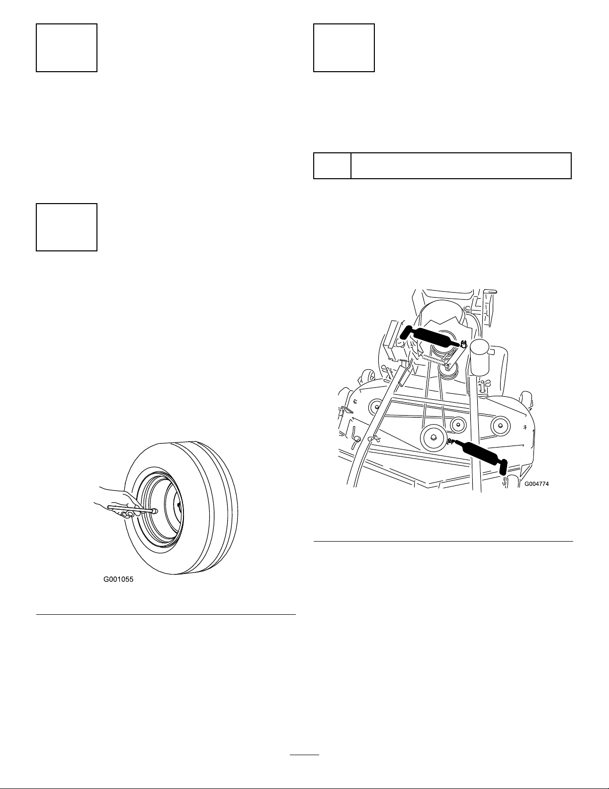
CheckingtheTirePressure
NoPartsRequired
Procedure
Pressure:12to14psi(83to97kPa)
Pressurefor60inchmowers:14to16psi(97to110kPa)
CheckingtheIdlerArmsfor
Grease(FloatingDeckModels)
Partsneededforthisprocedure:
1tube
Procedure
1.Removethecarrierframecover.
2.Checkthemowerbeltidlerarmforgrease(
3.Installthecarriercover.
Number2generalpurposelithiumbaseor
molybdenumbasegrease.(Purchaseseparately.)
orFigure3).
Figure2
Note:Thefrontcasterwheelisasemi-pneumatictire
anddoesnotneedtobechecked.
Checktheairpressureinthedrivetires.
Figure1
Figure2
40inch,48inch,and52inchMowerDeckshown
3
Page 4
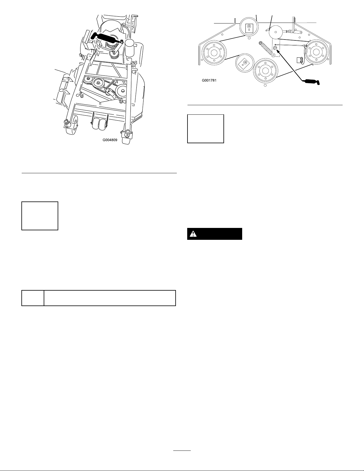
Figure4
5
Figure3
36inchMowerDeckshown
4.Undertheenginedeck,checkthePTOdrivebelt
idlerarmforgrease.
4
CheckingtheMowerBeltIdler
ArmforGrease(FixedDeck
Models)
Partsneededforthisprocedure:
1tube
Procedure
1.Removethemowerdeckcover.
2.Checkthemowerbeltidlerarmforgrease(Figure4).
3.Installthemowerdeckcover.
Number2generalpurposelithiumbaseor
molybdenumbasegrease.(Purchaseseparately.)
PreparingtheGrassDeector
NoPartsRequired
Procedure
Checkifyourmachinehasthegrassdeectorspring
installedcorrectly.Thegrassdeectorneedstohave
downwardtension.
WARNING
Anuncovereddischargeopeningcouldallowthe
lawnmowertothrowobjectsintheoperator’sor
bystander’sdirectionandresultinseriousinjuryor
death.Also,contactwiththebladecouldoccur.
Neveroperatethelawnmowerwiththegrass
deectorremovedunlessyouinstallacoverplate,a
mulchplate,oragrasschuteandcatcher.
1.MakesuretheLendofspringisinstalledbehind
thedeckedgebeforeinstallingtheboltasshownin
Figure5.
2.PlacetheJhookendofspringaroundgrassdeector
(Figure5).
Important:Thegrassdeectormustbefreeto
rotatewithdownwardtension.Liftthedeector
uptothefullopenpositionandensurethatit
rotatesfreelywithoutbindingintothefulldown
position.
4
Page 5

FixedDeckShown
Figure5
7
InstallingtheMufer
Partsneededforthisprocedure:
1
Mufer
4
Curvedwasher
1
Mufershield
4
Bolt(M8x25mm)
1
Muferclamp
1
Mufershieldbracket
4
Sidelocknut
1.GrassDeector4.Lendofspring,place
2.Spring
3.Jhookendofspring
behinddeckedgebefore
installingbolt
5.Deckedge
6
AdjustingtheAnti-Scalp
Rollers(FloatingDeckModels)
NoPartsRequired
Procedure
Adjusttheanti-scalprollers;refertoAdjustingthe
Anti-ScalpRollersintheOperator’sManual.
Procedure
1.Slidethemuferclampontothemuferinlet
andslidethemuferontotheexhaustmanifold
Figure6).
(
2.Alignthetwomountingholesonthemuferwith
thetwomountingslotsonthebracketattachedto
theengine.
3.Slidethemufershielddownoverthetopofthe
mufer.
4.Install2bolts(M8x25mm)and2curvedwashers
throughthemufershield,muferandmounting
bracket(
5.Attachthemufershieldbrackettothemufer
mountingbracketandsecuretheboltswith2side
locknuts.Torquethenutsto132in-lb(14.9N-m).
6.Install2bolts(M8x25mm)and2curvedwashers
throughthemufershieldandthemufershield
bracket.Securetheboltswith2sidelocknutsand
torquethemto132in-lb(14.9N-m)(
Figure6).
Figure6).
7.Tightenthemuferclampuntilthereisnogapleft
inthesplitstyleclamp.
5
Page 6

g013784
1 2 3
6
5
4
7
8
9
10
11
3
Figure6
1.Mufershield7.Engineexhaustmanifold
2.Curvedwasher8.Muferclamp
3.Bolt,M8x25mm
4.Mufershieldbracket10.Mufer
5.Sidelocknut11.Curvedwasher
6.Bracketattachedtothe
engine
9.Muferinlet
9
AddingFueltotheMachine
NoPartsRequired
Procedure
Addgasolinetothemachinebeforestartingit.Refer
toyourOperator’ sManual.forthecorrectfueland
procedure.
10
CheckingtheHydraulicOil
LevelforMowerswithHydro
Drive
NoPartsRequired
Procedure
Beforeyoustarttheengineandusethemachine,check
thehydraulicoillevelinthetank;refertoCheckingthe
HydraulicOilLevelintheOperator’sManual.
8
CheckingtheEngineOilLevel
NoPartsRequired
Procedure
Beforeyoustarttheengineandusethemachine,check
theoillevelintheenginecrankcase;refertoChecking
theEngineOilLevelintheOperator’ sManual.
6
Page 7

11
ActivatingtheBatteryfor
MowerswithElectricStart
Partsneededforthisprocedure:
80
ounces
Bulkelectrolytewith1.265specicgravity(Purchase
fromabatterysupplyoutlet.)
Figure7
Procedure
WARNING
CALIFORNIA
Proposition65Warning
Batteryposts,terminals,andrelated
accessoriescontainleadandleadcompounds,
chemicalsknowntotheStateofCalifornia
tocausecancerandreproductiveharm.
Washhandsafterhandling .
DANGER
Batteryelectrolytecontainssulfuricacidwhichisa
deadlypoisonandcausessevereburns.
Donotdrinkelectrolyteandavoidcontactwith
skin,eyesorclothing.Wearsafetyglassestoshield
youreyesandrubberglovestoprotectyourhands.
Fillthebatterywherecleanwaterisalwaysavailable
forushingtheskin.
Followallinstructionsandcomplywithallsafety
messagesontheelectrolytecontainer.
3.Slowlypourelectrolyteintoeachbatterycelluntilthe
levelisuptotheupperlineonthebatterycase.
Important:Donotoverllthebatterybecause
electrolyte(sulfuricacid)cancausesevere
corrosionanddamagetothechassis.
Figure8
4.Waitvetotenminutesafterllingthebatterycells.
Addelectrolyte,ifnecessary,untiltheelectrolyte
levelisuptotheupperlineonthebatterycase.
5.Installthebatteryventcaps(Figure9).
1.Removethebatteryfromthemachine.Refertothe
Operator’sManualforinstructions.
Important:Neverllthebatterywith
electrolytewhilethebatteryisinstalledonthe
machine.Electrolytecanbespilledonother
partsandcausecorrosion.
2.Cleanthetopofthebatteryandremovethevent
caps(Figure9).
Figure9
1.Fillcaps3.Lowerline
2.Upperline
7
Page 8

12
ChargingtheBatteryfor
MowerswithElectricStart
NoPartsRequired
Procedure
WARNING
Chargingthebatteryproducesgassesthatcan
explodeandcauseseriousinjury.
•Keepcigarettes,sparksandamesawayfrom
thebattery.
•Makesuretheignitionswitchisoff.
•Ventilatewhenchargingorusingthebatteryin
anenclosedspace.
Important:Donotrunthemachinewiththe
batterydisconnected;electricaldamagemayoccur
totheengine.
Chargethebattery.RefertotheOperator’sManualfor
instructions.
Figure10
13
CheckingtheMachineBeforeDeliverytotheCustomer
NoPartsRequired
Procedure
Beforedeliveringthemachinetothecustomer,ensurethatyouperformorhaveperformedtheprocedureslistedin
thefollowingtableandinitialeachwhennished.RefertotheOperator’sManualforinstructionsonperforming
theseprocedures.
Initial
Checkthetirepressure.
Checkthelevelofthemower.
Checktheengineoillevel.
Forhydraulicdrivenmowers,checkthehydraulicuidlevel.
Checktheadjustmentoftheparkingbrake.
Ensurethatthemachinetrackscorrectly;refertotheOperator’sManualfortheadjustmentprocedure.
Checkthesafetyinterlocksystem;refertotheOperator’sManual.
EnsurethatthePTOworks.
Checkallfastenersyouinstalledtoensurethattheyaretight.
CheckProcedure
Whenyounishsettingupthemachine,signanddateinthespaceprovidedbelow:
Signature:
Date:
8
Page 9

14
DeliveringtheMachinetotheCustomer
Partsneededforthisprocedure:
1
Operator’sManual
1
EngineOwner’sManual
1Enginewarrantyliterature
1
RegistrationCard
1
Operatortrainingmaterial
1Accessorybrochure
1Key
1
Oildrainhose
Procedure
Atdelivery,Fillinthemodelandserialnumberandcompletetheitemslistedinthefollowingtableandinitial
eachwhennished.
ModelNo.
SerialNo.
9
Page 10

DealerInitial
CustomerInitialCheckProcedure
Showthecustomerwherethefollowingfeaturesarelocatedandhowtheyfunction:
•
Fueltankcap
•
Oilllcap/Oildipstick
•
Sparkplug(s)
•
Engineoillter
•
Engineoildrain
•
Fuellter
•
Airlter
•
Hydraulicuidreservoir(ifapplicable)
•
Hydrauliclter(ifapplicable)
•
Hydraulicbypassvalves(ifapplicable)
•
Battery(ifapplicable)
•
Ignitionswitch
•
Throttlelever
•
Chokelever
•
Powertakeoffswitch(PTO)
•
Motioncontrols
•
Parkingbrake
•
Mowerheight-of-cut
•
Mowerdeckowbafe
RefertotheOperator’sManualtopointoutsafetyprocedures,operation,and
maintenanceprocedures.
ReviewthewarrantystatementasshownintheOperator’sManual.
Describethepostsaleserviceproceduresforyourstore.
Assistthecustomerinllingoutandmailingtheregistrationcardorregisteronlineat
www.T oro.com
MakesurethatthecustomerreceivestheOperator’sManual,EngineOwner’sManual,
SetUpInstructions,andoperatortrainingmaterial.
MakesurethecustomerknowsthePartsCatalogisavailableatwww.T oro.com.
Assistthecustomerinloadingthemower.
Note:Whenyou,thedealerrepresentative,havenisheddeliveringthemachinetothecustomer,signanddatein
thespaceprovidebelowandkeepacopyofthispagefordealerrecords.
Signature:Date:
Signature:Date:
10
Page 11

Notes:
11
Page 12

 Loading...