

Page 1
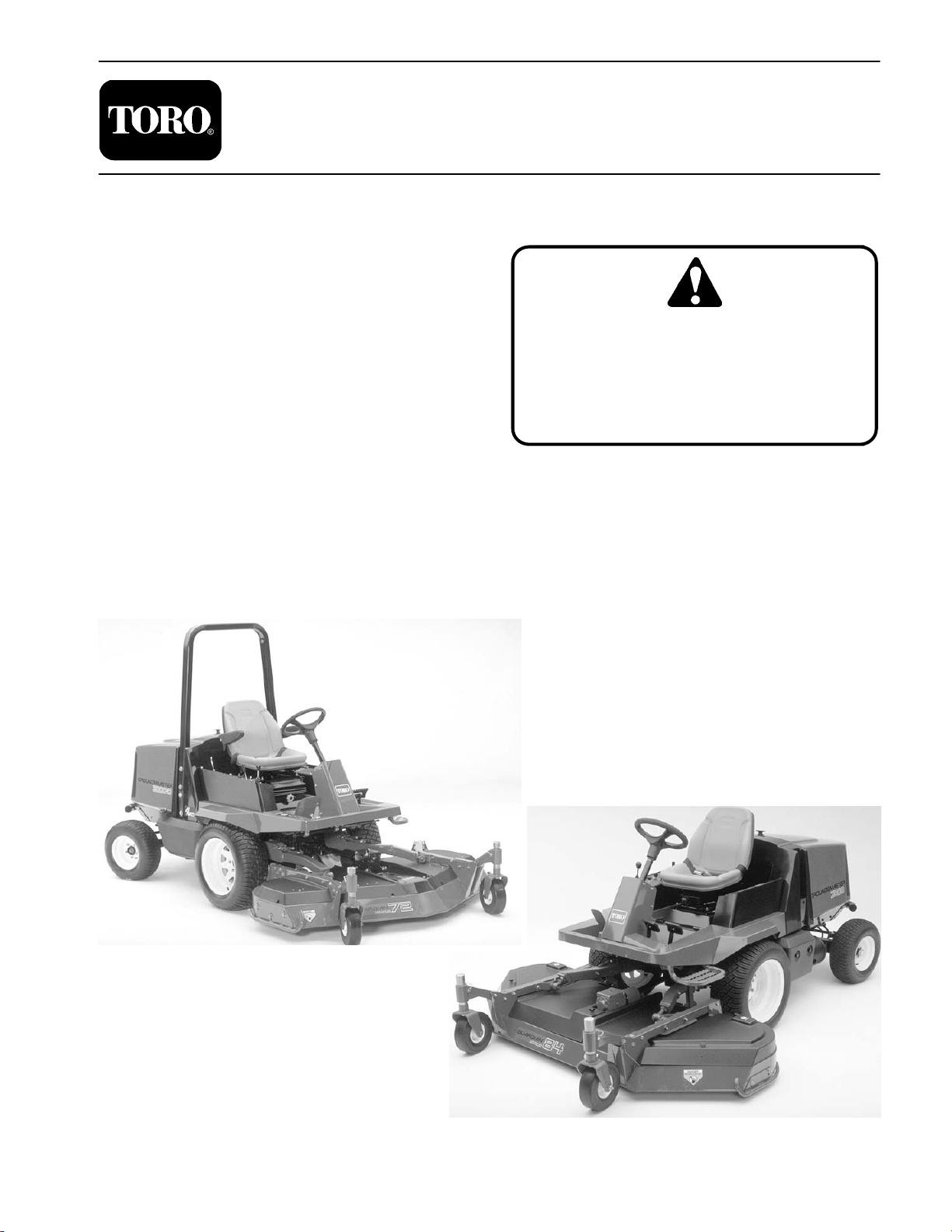
GroundsmasterR 3000/3000–D
Preface
The purpose of this publication is to provide the service
technician with information for troubleshooting, testing,
and repair of major systems and components on the
Groundsmaster 3000 and 3000–D.
REFER TO THE TRACTION UNIT AND CUTTING
UNIT OPERATOR’S MANUALS FOR OPERATING,
MAINTENANCE AND ADJUSTMENT INSTRUCTIONS. Space is provided in Chapter 2 of this book to
insert the Operator’s Manuals and Parts Catalogs for
your machine. Replacement Operator’s Manuals are
available by sending complete Model and Serial Number to:
The Toro Company
8111 Lyndale Avenue South
Bloomington, MN 55420
The Toro Company reserves the right to change product
specifications or this publication without notice.
Part No. 96890SL Rev. C
Service Manual
This safety symbol means DANGER, WARNING, or CAUTION, PERSONAL SAFETY
INSTRUCTION. When you see this symbol,
carefully read the instructions that follow.
Failure to obey the instructions may result in
personal injury.
NOTE: A NOTE will give general information about the
correct operation, maintenance, service, testing or repair of the machine.
IMPORTANT: The IMPORTANT notice will give important instructions which must be followed to prevent damage to systems or components on the
machine.
E The Toro Company – 1997, 1998, 2003, 2004
Page 2

Groundsmaster 3000/3000–D
Page 3

Table Of Contents
Chapter 1 – Safety
Safety Instructions . . . . . . . . . . . . . . . . . . . . . . . . . . 1 – 1
Safety and Instruction Decals
Chapter 2 – Product Records and Maintenance
Product Records . . . . . . . . . . . . . . . . . . . . . . . . . . . 2 – 1
Equivalents and Conversions
Torque Specifications
Maintenance Quick Reference Aid
Lubrication
Equipment Operation
and Service History Reports . . . . . . . . . . . . . . . . 2 – 9
Chapter 3 – Ford Gasoline Engine
Specifications . . . . . . . . . . . . . . . . . . . . . . . . . . . . . . 3 – 2
General Information
Adjustments
Service and Repairs
FORD VSG–411/413 ENGINE SERVICE MANUAL
Chapter 4 – Peugeot Diesel Engine
Specifications . . . . . . . . . . . . . . . . . . . . . . . . . . . . . . 4 – 2
Special Tools
Adjustments
Service and Repairs
PEUGEOT TUD5 ENGINE SERVICE MANUAL
. . . . . . . . . . . . . . . . . . . . . . . . . . . . . . . . 2 – 5
. . . . . . . . . . . . . . . . . . . . . . . . . . . . . . . 3 – 3
. . . . . . . . . . . . . . . . . . . . . . . . . . . . . . 4 – 3
. . . . . . . . . . . . . . . . . . . . . . . . . . . . . . . 4 – 8
. . . . . . . . . . . . . . . . . . . . . . . 2 – 3
. . . . . . . . . . . . . . . . . . . . . . . . . 3 – 2
. . . . . . . . . . . . . . . . . . . . . . . . 3 – 4
. . . . . . . . . . . . . . . . . . . . . . . . 4 – 9
. . . . . . . . . . . . . . . . 1 – 4
. . . . . . . . . . . . . . . . 2 – 2
. . . . . . . . . . . . 2 – 4
Chapter 5 – Hydraulic System and Transaxle
Specifications . . . . . . . . . . . . . . . . . . . . . . . . . . . . . . 5 – 2
General Information
Hydraulic Schematics
Hydraulic Components
Special Tools
Testing
Adjustments
Service and Repairs
SAUER–SUNDSTRAND IHT SERVICE MANUAL
Chapter 6 – Electrical System
Wiring Schematics . . . . . . . . . . . . . . . . . . . . . . . . . . 6 – 2
Special Tools
Troubleshooting (GM3000)
Troubleshooting (GM3000–D)
Electrical System Quick Checks
Component Identification and Testing
Service and Repairs
Chapter 7 – Rear Axle (2WD)
Adjustments . . . . . . . . . . . . . . . . . . . . . . . . . . . . . . . 7 – 2
Service and Repairs
Chapter 8 – Rear Axle (4WD)
Adjustments . . . . . . . . . . . . . . . . . . . . . . . . . . . . . . . 8 – 2
Service and Repairs
. . . . . . . . . . . . . . . . . . . . . . . . . . . . . . . . . . . 5 – 11
. . . . . . . . . . . . . . . . . . . . . . . . . . . . . . 5 – 19
. . . . . . . . . . . . . . . . . . . . . . . . . 5 – 3
. . . . . . . . . . . . . . . . . . . . . . . 5 – 6
. . . . . . . . . . . . . . . . . . . . . . 5 – 8
. . . . . . . . . . . . . . . . . . . . . . . . . . . . . . 5 – 9
. . . . . . . . . . . . . . . . . . . . . . . 5 – 20
. . . . . . . . . . . . . . . . . . . . . . . . . . . . . . 6 – 3
. . . . . . . . . . . . . . . . . . 6 – 6
. . . . . . . . . . . . . . . . 6 – 6
. . . . . . . . . . . . . . 6 – 8
. . . . . . . . . . 6 – 9
. . . . . . . . . . . . . . . . . . . . . . . 6 – 35
. . . . . . . . . . . . . . . . . . . . . . . . 7 – 3
. . . . . . . . . . . . . . . . . . . . . . . . 8 – 3
SafetyProduct Records
and Maintenance
Engine
Ford Gasoline
Engine
Peugeot Diesel
and Transaxle
Hydraulic SystemElectrical
System
2WD Rear Axle
4WD Rear Axle
Groundsmaster 3000/3000–D
Page 4

Groundsmaster 3000/3000–D
Page 5

Table of Contents (continued)
Chapter 9 – 84I Cutting Units
Specifications . . . . . . . . . . . . . . . . . . . . . . . . . . . . . . 9 – 2
Adjustments . . . . . . . . . . . . . . . . . . . . . . . . . . . . . . . 9 – 3
Service and Repairs . . . . . . . . . . . . . . . . . . . . . . . . 9 – 7
Chapter 10 – Contour 82I Cutting Unit
Specifications
Adjustments . . . . . . . . . . . . . . . . . . . . . . . . . . . . . . 10 – 3
Service and Repairs . . . . . . . . . . . . . . . . . . . . . . 10 – 7
. . . . . . . . . . . . . . . . . . . . . . . . . . . . . 10 – 2
Chapter 11 – 72I Cutting Units
Specifications
Adjustments . . . . . . . . . . . . . . . . . . . . . . . . . . . . . . 11 – 3
Service and Repairs . . . . . . . . . . . . . . . . . . . . . . . 11 – 8
Chapter 12 – Electrical Diagrams
Groundsmaster 3000
Groundsmaster 3000–D . . . . . . . . . . . . . . . . . . 12 – 10
. . . . . . . . . . . . . . . . . . . . . . . . . . . . . 11 – 2
. . . . . . . . . . . . . . . . . . . . . . 12 – 3
84 inchContour 82
Cutting Units
Cutting Unit
72 inch
Cutting Units
Electrical
Diagrams
Groundsmaster 3000/3000–D
Page 6

Groundsmaster 3000/3000–D
Page 7
Table of Contents
Chapter 1
Safety
Safety
SAFETY INSTRUCTIONS . . . . . . . . . . . . . . . . . . . . . . 1
Before Operating . . . . . . . . . . . . . . . . . . . . . . . . . . . . 1
While Operating . . . . . . . . . . . . . . . . . . . . . . . . . . . . . 2
Safety Instructions
The GROUNDSMASTERR 3000 and 3000-D was
tested and certified by TORO for compliance with the
B71.4—1990 specifications of the American National
Standards Institute. Although hazard control and accident prevention partially are dependent upon the design
and configuration of the machine, these factors are also
dependent upon the awareness, concern, and proper
training of the personnel involved in the operation, transport, maintenance, and storage of the machine. Improper use or maintenance of the machine can result in injury
or death. To reduce the potential for injury or death, comply with the following safety instructions.
Before Operating
1. Read and understand the contents of this manual
before starting and operating the machine. Become familiar with all controls and know how to stop quickly. A
free replacement manual is available by sending complete Model and Serial Numbers to:
The Toro Company
8111 Lyndale Avenue South
Minneapolis, Minnesota 55420–1196.
Use the Model and Serial Number when referring to your
machine. If you have questions about this Service
Manual, please contact:
The Toro Company
Commercial Service Department
8111 Lyndale Avenue South
Minneapolis, Minnesota 55420.
Maintenance and Service . . . . . . . . . . . . . . . . . . . . . 3
SAFETY AND INSTRUCTION DECALS
. . . . . . . . . . 4
CAUTION
TO REDUCE THE POTENTIAL FOR INJURY
OR DEA TH, COMPL Y WITH THE FOLLOWING
SAFETY INSTRUCTIONS.
3. Never operate machine when under the influence of
drugs or alcohol.
4. Remove all debris or other objects that might be
picked up and thrown by cutter blades or fast moving
components from other attached implements. Keep all
bystanders away from the operating area.
5. Keep all shields and safety devices in place. If a
shield, safety device, or decal is defective or damaged,
repair or replace it before operation is commenced.
Also, tighten any loose nuts, bolts, and screws to insure
machine is in safe operating condition.
6. Do not wear loose–fitting clothing because it could
get caught in moving parts. Always wear long pants and
substantial shoes. Wearing safety glasses, safety
shoes, and a helmet is advisable and required by some
local ordinances and insurance regulations.
2. Never allow children to operate the machine. Do not
allow adults to operate the machine without proper
instruction. Only trained operators, skilled in slope operation and who have read this manual should operate
this machine.
Groundsmaster 3000/3000–D
Page 1 – 1
Safety
Page 8

7. Check interlock switches daily for proper operation.
Do not rely entirely on safety switches -shut off engine
before getting off seat. If a switch fails, replace it before
operating the machine. The interlock system is for your
protection, so do not bypass it. Replace all interlock
switches every two years. Interlock switches should be
adjusted so:
A. Engine cannot be started unless traction pedal
is released (neutral position).
B. Engine stops if operator gets off seat when
traction pedal is depressed.
C. PTO disengages if operator gets off seat when
PTO lever is ENGAGED (on position).
8. Fill fuel tank with diesel fuel before starting the en-
gine. Avoid spilling any fuel. Since diesel fuel is flammable, handle it carefully.
A. Use an approved fuel container.
B. Do not fill fuel tank when engine is hot or
running.
C. Do not smoke while handling fuel.
D. Fill fuel tank outdoors and up to about one
inch (25 mm) from the top of the tank, not
the filler neck.
E. Wipe up any spilled fuel.
9. Sit on the seat when starting the engine and operat-
ing the machine.
10. Always use seat belt and ROPS together. Make
sure seat is latched.
11. Before starting the engine:
A. Engage parking brake.
B. Make sure traction pedal is in neutral.
C. After engine is started, release parking brake
and keep foot off traction pedal. Machine must not
move. If movement is evident, the neutral return
mechanism is adjusted incorrectly. Shut engine
off and adjust until machine does not move when
traction pedal is released.
12. Do not run the engine in a confined area without ad-
equate ventilation. Exhaust fumes are hazardous and
could possibly be deadly.
13. Maximum seating capacity is one person. There-
fore, never carry passengers.
14. This traction unit is intended to be used with an im-
plement. Refer to implement operator’s manual for
sound and vibration information and rear weight requirements.
15. Check carefully for overhead clearances before
driving under any objects.
While Operating
16. Using the machine demands the operator’s com-
plete attention. To prevent loss of control:
A. Operate only in daylight or when there is good
artificial light.
B. Drive slowly.
C. Avoid sudden stops and starts.
D. Look behind machine before backing up.
E. Watch for holes or other hidden hazards.
F. Do not drive close to a sand trap, ditch, creek,
or hazard.
G. Reduce speed when making sharp turns and
when turning on a hillside.
H. The cutting deck must be lowered when going
down slopes for steering control.
17. Operator must be skilled and trained in how to drive
on hillsides. Failure to use caution on slopes or hills may
cause loss of control and vehicle to tip or roll possibly resulting in personal injury or death.
18. Traverse slopes carefully. Do not start or stop sud-
denly when traversing slopes or when traveling uphill or
downhill.
19. If engine stalls or machine loses headway and can-
not make it to the top of a slope, do not turn machine
around. Always back slowly straight down the slope.
20. This product is designed to drive objects into the
ground where they lose energy quickly in grassy areas.
However, don’t take an injury risk!!
appears unexpectedly in or near the mowing area,
STOP MOWING. Careless operation, combined with
terrain angles, ricochets, or improperly positioned
guards, can lead to thrown object injuries. Do not resume mowing until area is cleared.
21. Never raise the cutting unit or other attached imple-
ment while the blades or other parts are rotating.
22. If cutting blades or other implement components
strike a solid object or the machine vibrates abnormally,
disengage PTO, move throttle to SLOW, set parking
brake, and shut engine off. Remove key from switch to
prevent possibility of accidental starting. Check cutting
unit or other implement and traction unit for damage and
defective parts. Repair any damage before restarting
the engine and operating the implement or cutting unit.
Assure cutting unit blades are in good condition and
blade bolts are torqued to proper specifications (See
Cutting Deck Operator’s Manual).
23. To stop machine, remove foot from traction pedal
and use brakes. Gradually reversing the traction pedal
can provide additional braking.
When a person or pet
Safety
Page 1 – 2
Groundsmaster 3000/3000–D
Page 9

24. Do not touch engine, muffler, or radiator while en-
gine is running or soon after it has stopped. These areas
could be hot enough to cause a burn.
25. Lower the cutting unit or other attached implement
to the ground and remove key from switch whenever
machine is left unattended.
Maintenance
26. Before getting off the seat:
A. Move traction pedal to neutral position and remove foot from pedal.
B. Set the parking brake and disengage the PTO.
C. Shut the engine off and remove key from igni-
tion switch. Wait for all movement to stop before
getting off the seat.
Safety
27. Remove key from ignition switch to prevent acci-
dental starting of the engine when servicing, adjusting,
or storing the machine.
28. If major repairs are ever needed or assistance is de-
sired, contact an Authorized TORO Distributor.
29. To reduce potential fire hazard, keep the engine free
of excessive grease, grass, leaves, and accumulations
of dirt. Never wash a warm engine or electrical connections with water.
30. If the cutting unit discharge area ever plugs, disen-
gage PTO and shut engine off before removing the obstruction.
31. Make sure machine is in safe operating condition by
keeping nuts, bolts, and screws tight. Check attachment
mounting hardware and all cutting unit blade mounting
bolts frequently to assure they are torqued to proper
specifications.
32. Periodically inspect the roll bar and roll bar mount-
ing. Repair, as necessary. Do not weld, cut, drill, or
modify roll bar in any manner.
33. Make sure all hydraulic line connectors are tight,
and all hydraulic hoses and lines are in good condition
before applying pressure to the system.
34. Keep body and hands away from pin hole leaks or
nozzles that eject hydraulic fluid under high pressure.
Use paper or cardboard, not hands, to search for leaks.
Hydraulic fluid escaping under pressure can have sufficient force to penetrate skin and do serious damage. If
fluid is ejected into the skin, it must be surgically removed within a few hours by a doctor familiar with this
form of injury or gangrene may result.
35. Before disconnecting or performing any work on the
hydraulic system, all pressure in system must be relieved by stopping engine and lowering implement to the
ground.
36. If the engine must be running to perform mainte-
nance or an adjustment, keep clear of PTO shaft, cutting
unit blades, and other moving parts.
37. Do not overspeed the engine by changing the gov-
ernor settings. To ensure safety and accuracy, have an
Authorized TORO Distributor check maximum engine
speed with a tachometer.
38. Engine must be shut off before checking oil or ad-
ding oil to the crankcase.
39. At the time of manufacture, the machine conformed
to safety standards in effect for riding mowers. To ensure
optimum performance and continued safety certification
of the machine, use genuine TORO replacement parts
and accessories. Replacement parts and accessories
made by other manufacturers may result in non–conformance with the safety standards, and the warranty may
be voided.
Groundsmaster 3000/3000–D
Page 1 – 3
Safety
Page 10

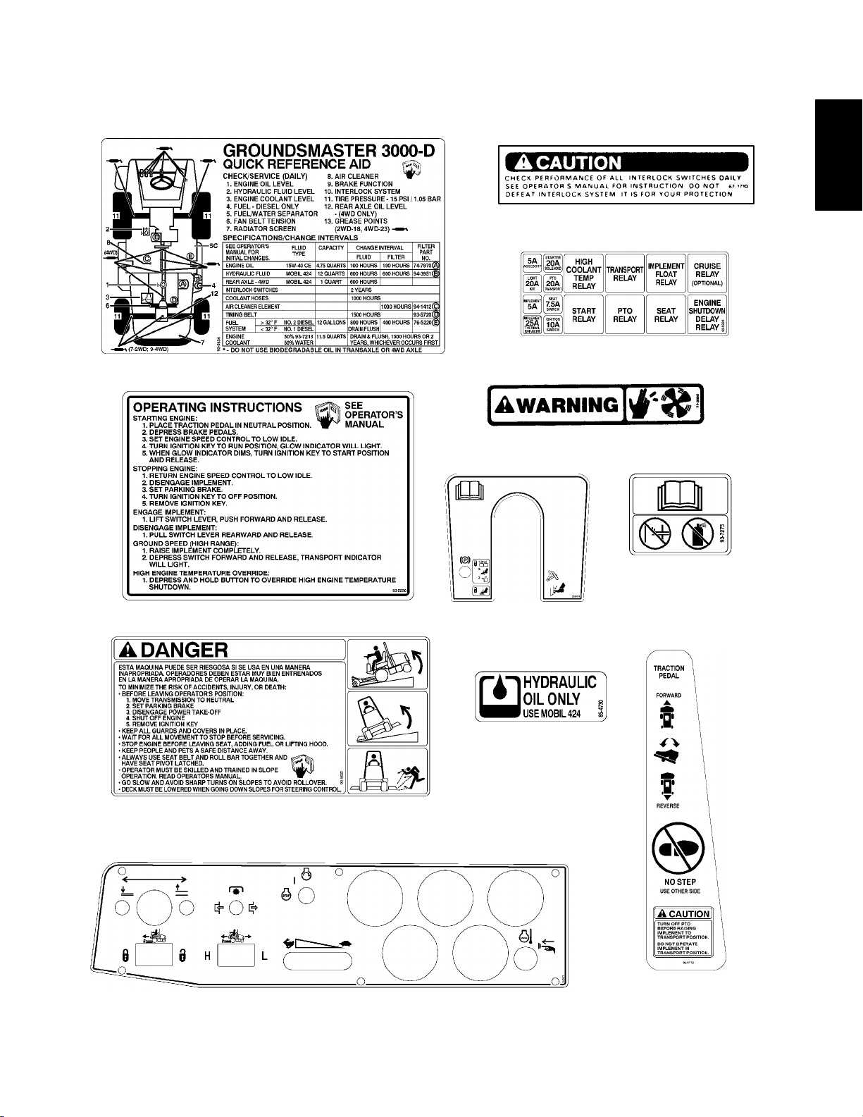
Safety and Instruction Decals (Groundsmaster 3000)
The following safety and instruction decals are mounted on the traction unit. If any decal becomes damaged or illegible, install a new decal. Part numbers are listed below or in your parts catalog.
On Side of Tool Box
(Part No. 67–1710)
Next to Right Side of Seat
(Part No. 93–5935)
On Fuse Compartment Cover
(Part No. 93–5931)
In Compartment Behind Control panel
(Part No. 93–5933)
ON FAN SHROUD
(Part No. 77–3100)
On Hood
(Part No. 93–6328)
On Right Side Of Center
Shroud
(Part No. 93–5617)
On Steering Tower
(Part No. 95–0814)
Safety
On Tool Box Cover
(Part No. 93–5621)
On Control Panel
(Part No. 93–5426)
On Frame Above Front Axle
(Part No. 85–4730)
Page 1 – 4 Rev. A
On Frame Next to Traction Pedal
(Part No. 92–5772)
Groundsmaster 3000/3000–D
Page 11
Safety and Instruction Decals (Groundsmaster 3000–D)
The following safety and instruction decals are mounted on the traction unit. If any decal becomes damaged or illegible, install a new decal. Part numbers are listed below or in your parts catalog.
On Side of Tool Box
(Part No. 67–1710)
In Compartment Behind Control panel
Next to Right Side of Seat
(Part No. 93–5934)
(Part No. 93–5932)
ON FAN SHROUD
(Part No. 77–3100)
Safety
On Fuse Compartment Cover
(Part No. 93–5930)
On Tool Box Cover
(Part No. 93–5621– Model 30301)
(Part No. 93–5622– Model 30302)
On Radiator Near Inlet
(Part No. 93–7275)
On Steering Tower
(Part No. 95–0814)
On Frame Above Front Axle
(Part No. 85–4730)
Groundsmaster 3000/3000–D
On Control Panel
(Part No. 93–5425)
Page 1 – 5
Rev. A
On Frame Next to Traction Pedal
(Part No. 92–5772)
Safety
Page 12
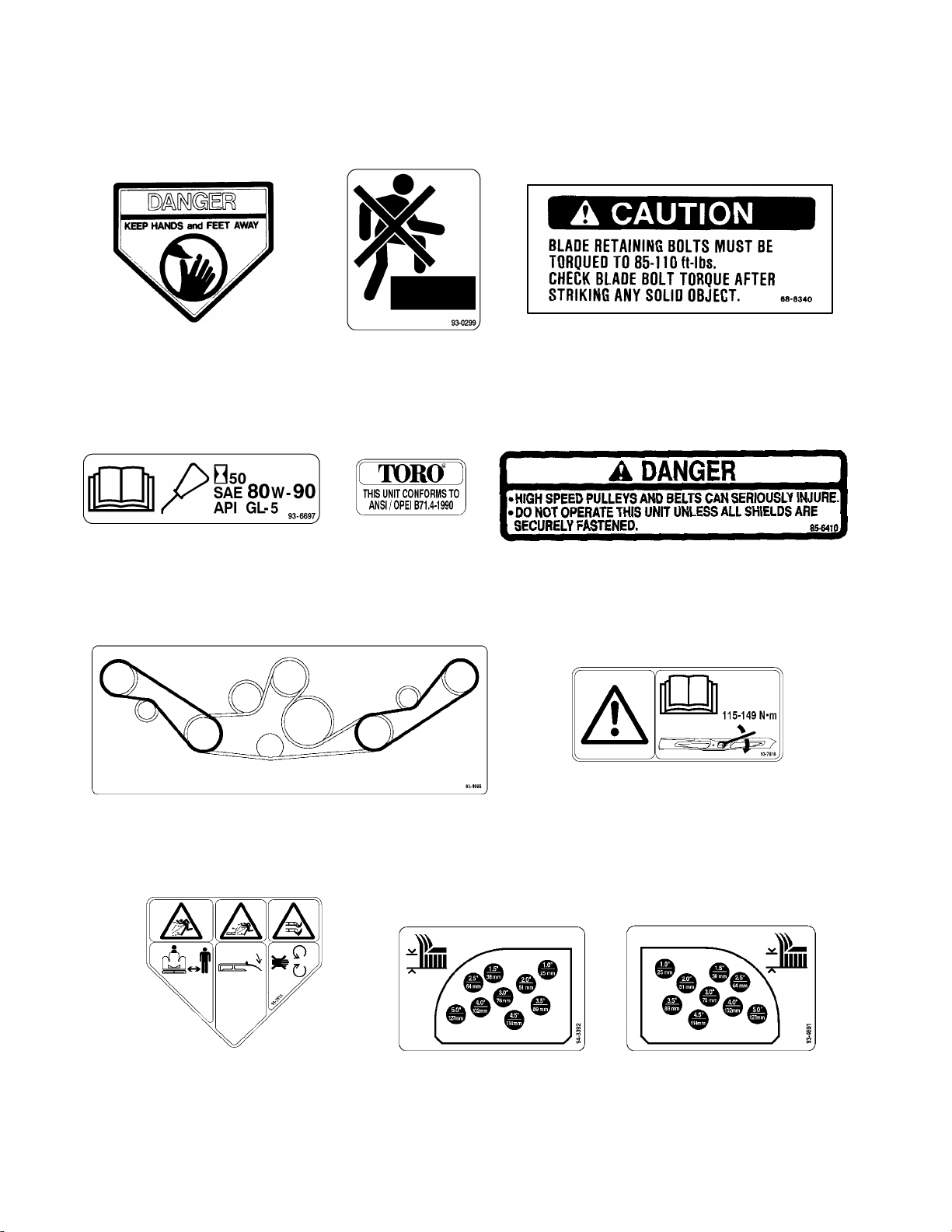
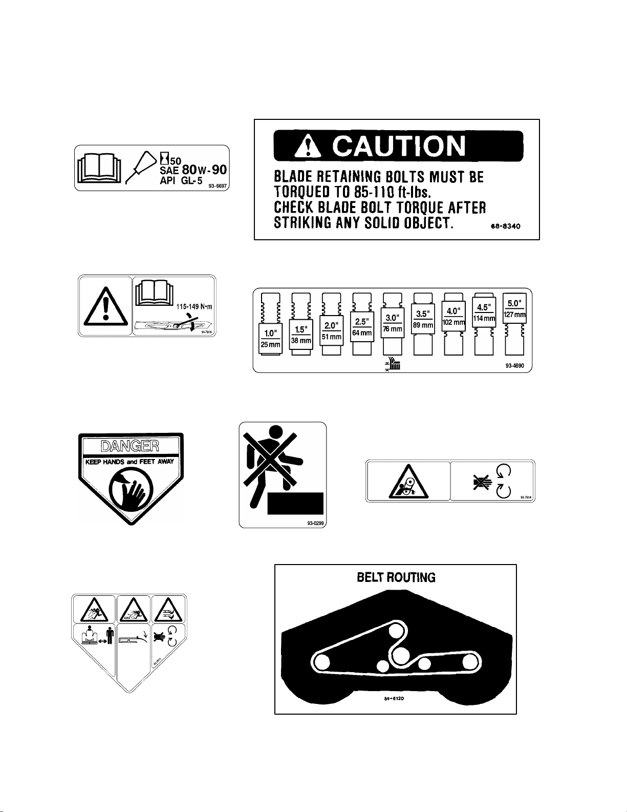
Safety and Instruction Decals (84I Cutting Units)
The following safety and instruction decals are mounted on the cutting unit. If any decal becomes damaged or illegible,
install a new decal. Part numbers are listed below or in your parts catalog.
On Each Corner Of
Cutting Unit
(Part No. 43–8480)
On Gearbox Base
(Part No. 93–6697)
On Right & Left Covers
(Part No. 93–0299)
On Front of Deck
(Part No. 88–1270)
On Front of Cutting Unit
(Part No. 68–8340)
On Deck Channels, Under Covers
(Part No. 85–6410)
Safety
On Right Rear Top of Deck Under Cover
(Part No. 93–4688)
On Each Corner Of
Cutting Unit
(Part No. 93–7815)
Replaces Decal Part No.
43–8480 for CE
On Right Rear Top of Deck On left Rear Top of Deck
Page 1 – 6 Rev. A
On Front of Cutting Unit
(Part No. 93–7818)
Replaces Decal Part No.
68–8340 for CE
Under Cover Under Cover
(Part No. 94–3392) (Part No. 93–4691)
Groundsmaster 3000/3000–D
Page 13

On Front of Deck
(Part No. 66–1340)
Safety
On Rear of Deck
(Part No. 66–6380)
On Rear Of Deck
(Part No. 93–7828)
Replaces Decal Part No.
66–6380 for CE
On Front Of Deck
(Part No. 93–7824)
Replaces Decal Part No.
66–1340 for CE
On Each Castor Arm
(Part No. 93–4690)
On Each Castor Arm
(Part No. 93–4894)
On Deck Channels, Under Covers
(Part No. 93–7814)
Replaces Decal Part No. 85–6410 for CE
Groundsmaster 3000/3000–D
Page 1 – 7
Rev. A
Safety
Page 14

Safety and Instruction Decals (Contour 82I Cutting Unit)
The following safety and instruction decals are mounted on the cutting unit. If any decal becomes damaged or illegible,
install a new decal. Part numbers are listed below or in your parts catalog.
On Sides of Right &
Left Chambers
(Part No. 43–8480)
On Top of Chamber 2
(Part No. 88–1270)
On Chamber 1 & 4 Castor Supports
(Part No. 95–6001)
On Right & Left Chambers
(Part No. 93–0299)
On Top of Chamber 3
(Part No. 93–7818)
Replaces Decal Part No.
68–8340 for CE
On Top of Chamber 3
(Part No. 68–8340)
On Sides of Right &
Left Chambers
(Part No. 93–7815)
Replaces Decal Part No.
43–8480 for CE
On Top of Rear Castor
(Chamber 1)
(Part No. 95–6003)
On Left Lift Arm On Right Lift Arm
(Part No. 95–6008) (Part No. 95–6005)
Safety
Page 1 – 8
On Top of Rear Castor
(Chambers 2 & 4)
(Part No. 95–6002)
On Side of Rear Support
(Chamber 3)
(Part No. 95–6004)
Groundsmaster 3000/3000–D
Page 15

Safety and Instruction Decals (Guardian 72I Recycler Cutting Unit)
The following safety and instruction decals are mounted on the cutting unit. If any decal becomes damaged or illegible,
install a new decal. Part numbers are listed below or in your parts catalog.
Safety
On Each Corner Of
Cutting Unit
(Part No. 43–8480)
On Gearbox Base
(Part No. 93–6697)
On Front of Cutting
Unit
(Part No. 93–7818)
Replaces Decal Part No.
68–8340 for CE
On Left Caster Arm
(Part No. 93–0299)
On Front of Deck
(Part No. 88–1270)
On Front of Cutting Unit
(Part No. 68–8340)
On Deck Channels, Under Covers
(Part No. 85–6410)
On Right Rear Top of Deck Under Cover
(Part No. 85–6120)
On Each Corner Of
Cutting Unit
(Part No. 93–7815)
Replaces Decal Part No.
43–8480 for CE
On Front Deck Hanger
(Part No. 93–4690)
Groundsmaster 3000/3000–D
On Right Rear Top of Deck On left Rear Top of Deck
(Part No. 94–3392)
(Part No. 93–4691)
On Deck Channels, Under Covers
(Part No. 93–7814)
Replaces Decal Part No. 85–6410 for CE
Page 1 – 9
Safety
Page 16
Safety and Instruction Decals (Rear Discharge 72I Cutting Unit)
The following safety and instruction decals are mounted on the cutting unit. If any decal becomes damaged or illegible,
install a new decal. Part numbers are listed below or in your parts catalog.
On Gearbox Base
(Part No. 93–6697)
On Front of Deck
(Part No. 68–8340)
On Front of Deck
(Part No. 93–7818)
Replaces Decal Part No.
68–8340 for CE
On Each Corner Of
Deck
(Part No. 43–8480)
On Left Caster Arm
(Part No. 93–0299)
On Front Deck Hanger
(Part No. 93–4690)
On Deck Channels, Under Covers
(Part No. 93–7814)
Replaces Decal Part No. 85–6410 for CE
Safety
On Each Corner Of
Deck
(Part No. 93–7815)
Replaces Decal Part No.
43–8480 for CE
On Right Rear Top of Deck Under Cover
(Part No. 85–6120)
Page 1 – 10
Groundsmaster 3000/3000–D
Page 17

On Front of Deck
(Part No. 66–6380)
On Rear Of Deck
(Part No. 93–7828)
Replaces Decal Part No.
66–6380 for CE
On Rear Of Deck
(Part No. 93–4977)
On Front of Deck
(Part No. 66–1340)
On Deck Channels, Under Covers
(Part No. 85–6410)
On Right Rear Top of Deck On left Rear Top of Deck
(Part No. 94–3392) (Part No. 93–4691)
On Front Of Deck
(Part No. 93–7824)
Replaces Decal Part No.
66–1340 for CE
On Front of Deck
(Part No. 88–1270)
Groundsmaster 3000/3000–D
Page 1 – 11
Safety
Page 18

Safety
Page 1 – 12
Groundsmaster 3000/3000–D
Page 19

Product Records and Maintenance
Table of Contents
Chapter 2
PRODUCT RECORDS . . . . . . . . . . . . . . . . . . . . . . . . . 1
EQUIVALENTS AND CONVERSIONS . . . . . . . . . . . 2
Decimal and Millimeter Equivalents . . . . . . . . . . . . 2
U.S. to Metric Conversions . . . . . . . . . . . . . . . . . . . 2
TORQUE SPECIFICATIONS . . . . . . . . . . . . . . . . . . . 3
Capscrew Markings and Torque Values – U.S. . . 3
Capscrew Markings and Torque Values – Metric . 3
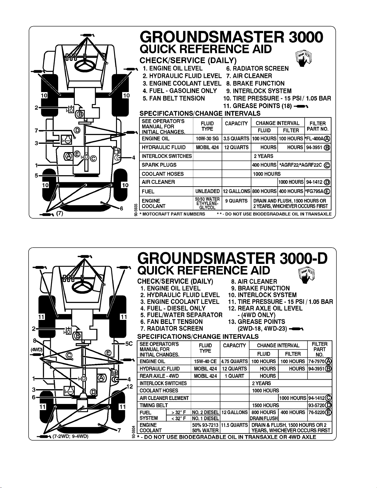
QUICK REFERENCE MAINTENANCE AID . . . . . . . 4
Product Records
Record information about your Groundsmaster 3000 or
3000–D on the OPERATION AND SERVICE HISTORY
REPORT form. Use this information when referring to
your machine.
LUBRICATION . . . . . . . . . . . . . . . . . . . . . . . . . . . . . . . . 5
Traction Unit . . . . . . . . . . . . . . . . . . . . . . . . . . . . . . . . 5
Cutting Units . . . . . . . . . . . . . . . . . . . . . . . . . . . . . . . . 6
OPERATION AND SERVICE HISTORY REPORTS 9
Insert Operator’s Manuals and Parts Catalogs for your
Groundsmaster 3000 or 3000–D at the end of this section.
Product Records
and Maintenance
Groundsmaster 3000/3000–D
Page 2 – 1
Product Records and Maintenance
Page 20

Equivalents and Conversions
Product Records and Maintenance
Page 2 – 2
Groundsmaster 3000/3000–D
Page 21
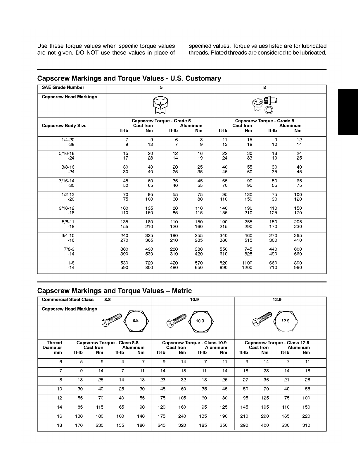
Torque Specifications
Product Records
and Maintenance
Groundsmaster 3000/3000–D
Page 2 – 3
Product Records and Maintenance
Page 22
800
800
Product Records and Maintenance
Page 2 – 4 Rev. A
800 800
400
Groundsmaster 3000/3000–D
Page 23
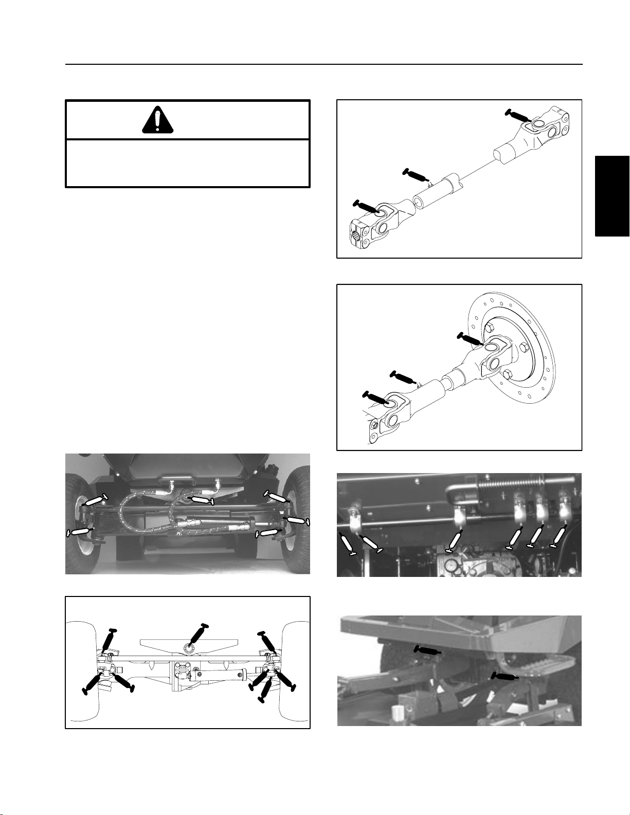
Lubrication
Traction Unit
CAUTION
Before servicing or making adjustments to the
machine, stop engine and remove key from the
switch.
The machine has grease fittings that must be lubricated
regularly with No. 2 General Purpose Lithium Base
Grease. If machine is operated under normal conditions, lubricate all bearings and bushings after every 50
hours of operation or immediately after every washing.
The grease fitting locations and quantities are:
2 Wheel Drive Models only–Steering cylinder ball joint,
Rear axle tie rod (2), Rear axle pivot (1) Rear Spindle
Shafts (2) (Fig. 1).
Figure 3
Product Records
and Maintenance
4 Wheel Drive Models only–Steering cylinder ball
joints, Rear axle tie rod (2), Rear axle pivot (1), Double
Cardan joints (2 ea. side) (Fig. 2) and Rear DrIve Shaft
(3) (Fig.3)
All Models–Intermediate Drive Shaft (3) (Fig. 4); Pedal
Pivots (5), Traction pedal (In square tube under floor
plate) (1) (Fig. 5) and Lift arm pivot (2) (Fig. 6).
Figure 1
Figure 4
Figure 5
Figure 2
Groundsmaster 3000/3000–D
Page 2 – 5
Figure 6
Product Records and Maintenance
Page 24
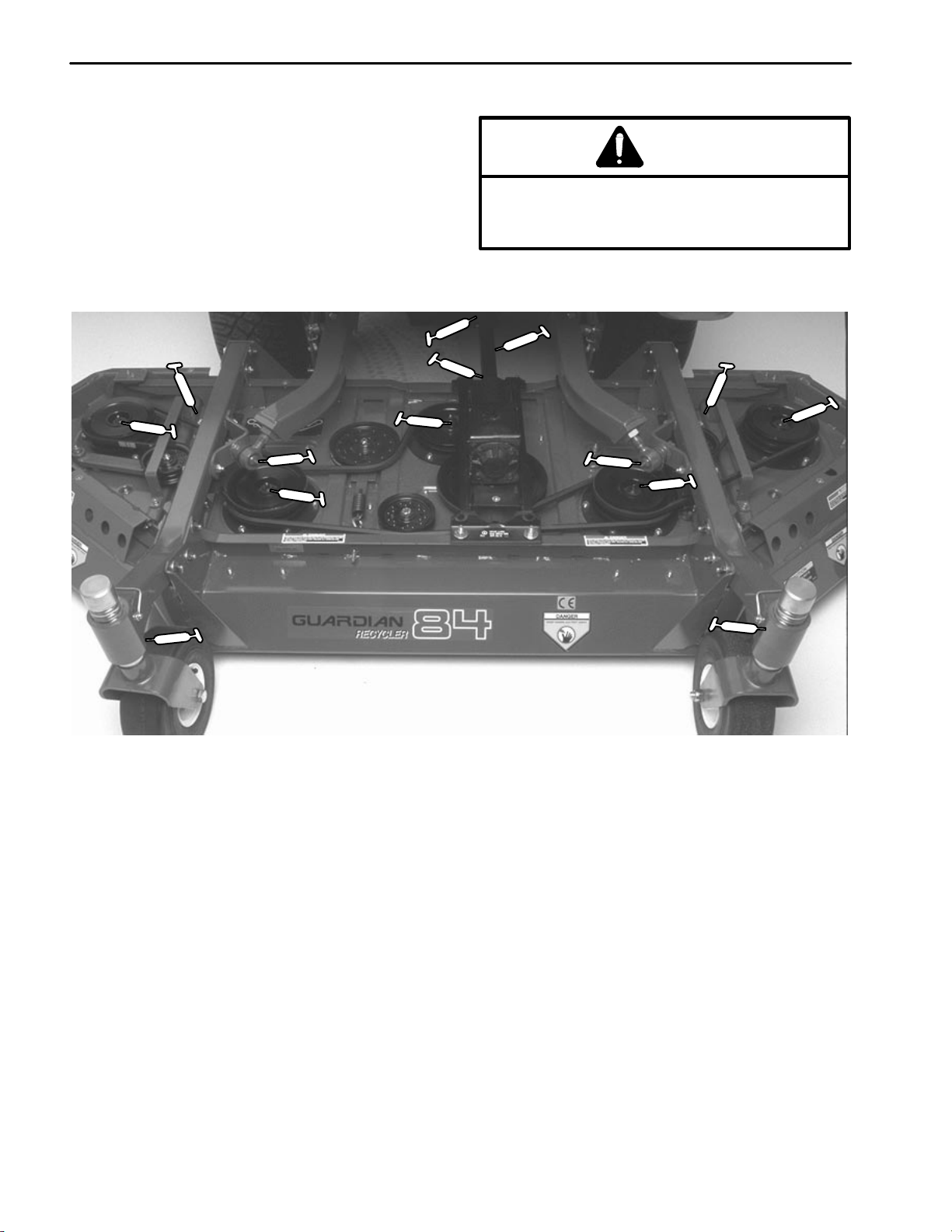
Cutting Units
If machine is operated under normal conditions, lubricate castor bearings and bushings with No. 2 general
purpose lithium base grease or molybdenum base
grease, after every 8 hours of operation or daily, whichever comes first. Lubricate fittings immediately after every washing, regardless of the interval listed.
Guardian 84I Recyler Cutting Unit
CAUTION
Before servicing or making adjustments to the
machine, stop engine and remove key from the
switch.
Product Records and Maintenance
Figure 7
Page 2 – 6
Groundsmaster 3000/3000–D
Page 25
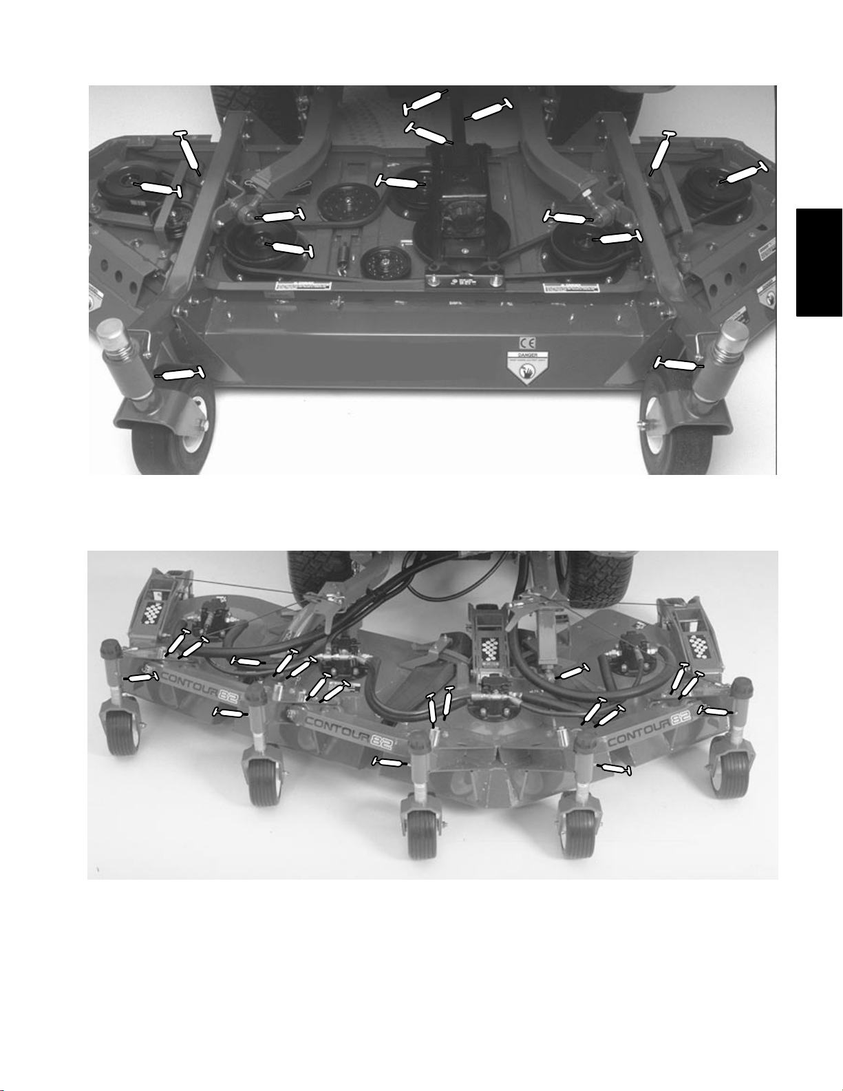
Rear Discharge 84I Cutting Unit
Product Records
and Maintenance
Contour 82I Cutting Unit
Figure 8
Groundsmaster 3000/3000–D
Figure 9
Page 2 – 7
Product Records and Maintenance
Page 26

Guardian 72I Recycler Cutting Unit
Figure 10
Rear Discharge 72I Cutting Unit
Product Records and Maintenance
Figure 11
Page 2 – 8
Groundsmaster 3000/3000–D
Page 27

EQUIPMENT OPERATION AND SERVICE HISTORY REPORT
for
GROUNDSMASTERR 3000
TORO Model and Serial Number: ______________–______________
Engine Numbers: _____________________________
Transmission Numbers: _____________________________
Drive Axle(s) Numbers: _____________________________
Date Purchased: _____________________________ Warranty Expires____________
Product Records
and Maintenance
Purchased From: _____________________________
_____________________________
_____________________________
Contacts: Parts _____________________________ Phone____________________
Service _____________________________ Phone____________________
Sales _____________________________ Phone____________________
Groundsmaster 3000/3000–D
Page 2 – 9
Product Records and Maintenance
Page 28
GroundsmasterR3000 Maintenance Schedule
Minimum Recommended Maintenance Intervals
Maintenance Procedure
Lubricate All Grease Fittings
Inspect Air Filter
Check Battery Level/Cable Connections
Check Cutting Unit Gearbox Oil Level
Clean Under Cutting Unit Belt Covers
Check Cutting Unit Drive Belt Adjustment
} Change Engine Oil and Filter
Inspect Cooling System Hoses
{
Check Fan, Governor and Alternator Belt Tension
{
Torque Wheel Lug Nuts
Check Governor Oil Level
Service Spark Arrester Muffler
Service Air Filter
Change Fuel Filter
Inspect Fuel Lines and Connections
Change Spark Plugs
} Check Engine RPM (idle and full throttle)
Torque Head and Adjust Valves
Change Cutting Unit Gearbox Oil
Every
50hrs
A Level
Service
Maintenance Interval & Service
Every
800hrs
Every
100hrs
B Level
Service
Every
200hrs
C Level
Service
Every
400hrs
D Level
Service
= Change Hydraulic Oil
= Change Hydraulic Oil Filter
Drain and Clean Fuel Tank
Pack Rear Axle Bearings
Check Rear Wheel Toe–In
{ Initial break in at 10 hours
} Initial break in at 50 hours
= Initial break in at 200 hours
Replace Moving Hoses
Replace Safety Switches
Cooling System Flush/Replace Fluid
(See Operator’s Manual for specifications and procedures.)
Product Records and Maintenance
Page 2 – 10
E Level
Service
Annual Recommendations:
Items listed are recommended every 1500
hours or 2 years, whichever occurs first.
Groundsmaster 3000/3000–D
Page 29
GroundsmasterR3000 Daily Maintenance Check List
Unit Designation: ____________
TORO ID #: ________–________
Daily Maintenance: (duplicate this page for routine use)
Check proper section of Operator’s Manual for fluid specifications
Maintenance
Check Item b
n Safety Interlock Operation
n Brake Operation
n Engine Oil & Fuel Level
n Cooling System Fluid Level
n Radiator & Screen for Debris
n Unusual Engine Noises
n Unusual Operating Noises
n Hydraulic System Oil Level
n Hydraulic Hoses for Damage
n Fluid Leaks
n Tire Pressure
n Instrument Operation
Lubricate All Grease Fittings
Touch–up Damaged Paint
1
= Immediately after every washing, regardless of the interval listed.
Daily Maintenance Check For Week Of _________________
MON TUES WED THURS FRI SAT SUN
1
Product Records
and Maintenance
Notation for areas of concern: Inspection performed by__________________
Item Date Information
1
2
3
4
5
6
7
8
Groundsmaster 3000/3000–D
Page 2 – 11
Product Records and Maintenance
Page 30
Date: ________________
Check Governor Oil Level
Torque Wheel Lug Nuts
Service Spark Arrestor Muffler
__________________________
A and B – Service Required
________________________________
_______________________________
_______________________________
_______________________________
Replace Moving Hoses
Replace Safety Switches
Cooling System Flush/Replace Fluid
_______________________________
Other – Annual Service & Specials
_______________________________
_______________________________
_______________________________
_______________________________
Remarks:
3000 Supervisor Maintenance Work Order
R
A B C D E Other
__________________–__________________
TORO I.D. #:
Service to perform (circle):
Groundsmaster
Unit Designation:
(Duplicate this page for routine use.)
Hours:
Technician:
_______________________________
Change Engine Oil and Filter
Inspect Cooling System Hoses
Check Tension of all drive belts
Lubricate All Grease Fittings
A– Service (every 50 hours) B – Service (every 100 hours) C – Service (every 200 hours)
Check Battery Level/Cable Connections
Inspect Air Filter
_______________________________
A – Service Required
Check Cutting Unit Gearbox Oil Level
_______________________________
Clean Under Cutting Unit Belt Covers
Check Cutting Unit Drive Belt Adjustment
_______________________________
________________________________
________________________________
_______________________________
________________________________
E – Service (every 800 hours)
Drain and Clean Fuel Tank
Pack Rear Axle Bearings
Change Fuel Filter
Service Air Filter
D – Service (every 400 hours)
Change Hydraulic Oil
Check Rear Wheel Toe–In
Inspect Fuel Lines and Connections
Change Hydraulic Filter
Change Spark Plugs
Check Engine RPM (idle & Full Throttle)
_______________________________
A, B, C, and D – Service Required
Torque Head Bolts and Adjust Valves
Change Cutting Unit Gearbox Oil
_______________________________
_______________________________
________________________________
A, B and C – Service Required
(See Operator’s and Service Manual for specifications and procedures.)
Product Records and Maintenance
Page 2 – 12
Groundsmaster 3000/3000–D
Page 31

EQUIPMENT OPERATION AND SERVICE HISTORY REPORT
for
GROUNDSMASTERR 3000–D
TORO Model and Serial Number: ______________–______________
Engine Numbers: _____________________________
Transmission Numbers: _____________________________
Drive Axle(s) Numbers: _____________________________
Date Purchased: _____________________________ Warranty Expires____________
Product Records
and Maintenance
Purchased From: _____________________________
_____________________________
_____________________________
Contacts: Parts _____________________________ Phone____________________
Service _____________________________ Phone____________________
Sales _____________________________ Phone____________________
Groundsmaster 3000/3000–D
Page 2 – 13
Product Records and Maintenance
Page 32

GroundsmasterR3000–D Maintenance Schedule
Minimum Recommended Maintenance Intervals
Maintenance Procedure Maintenance Interval & Service
Lubricate All Grease Fittings
Inspect Air Filter
Check Battery Level/Cable Connections
Check Cutting Unit Gearbox Oil Level
Clean Under Cutting Unit Belt Covers
Check Cutting Unit Drive Belt Adjustment
} Change Engine Oil and Filter
Inspect Cooling System Hoses
{
Check Fan and Alternator Belt Tension
{
Torque Wheel Lug Nuts
Service Air Filter
Change Fuel Filter
Inspect Fuel Lines and Connections
} Check Engine RPM (idle and full throttle)
Check Rear Axle Oil Level (4wd)
Change Cutting Unit Gearbox Oil
= Change Rear Axle Oil (4wd)
= Change Hydraulic Oil (see note below)
= Change Hydraulic Oil Filter (see note below)
Inspect Engine Timing Belt (see note below)
Drain and Clean Fuel Tank
Pack 2WD Rear Axle Bearings
Check Rear Wheel Toe–In
Every
50hrs
A Level
Service
Every
100hrs
B Level
Service
Every
200hrs
C Level
Service
Every
400hrs
D Level
Service
Every
800 hrs
E Level
Service
{ Initial break in at 10 hours
} Initial break in at 50 hours
= Initial break in at 200 hours
Replace Moving Hoses
Replace Safety Switches
Cooling System Flush/Replace Fluid
(See Operator’s Manual for specifications and procedures.)
NOTE: Replace Timing Belt after every 1500 hours of operation or if worn, cracked, oil soaked or
any time the Belt is removed or loosened.
NOTE: Replace Hydraulic Oil and Filter every 400 hours of operation if machine is equipped with
Model 30726 Auxiliary Hydraulic Kit.
Product Records and Maintenance
Page 2 – 14
Annual Recommendations:
Items listed are recommended every 1500
hours or 2 years, whichever occurs first.
Rev. B
Groundsmaster 3000/3000–D
Page 33

GroundsmasterR3000–D Daily Maintenance Check List
Unit Designation: ____________
TORO ID #: ________–________
Daily Maintenance: (duplicate this page for routine use)
Check proper section of Operator’s Manual for fluid specifications
Maintenance
Check Item b
n Safety Interlock Operation
n Brake Operation
n Engine Oil & Fuel Level
n Cooling System Fluid Level
Drain Water/Fuel Separator
n Radiator & Screen for Debris
n Unusual Engine Noises
n Unusual Operating Noises
n Hydraulic System Oil Level
n Hydraulic Hoses for Damage
n Fluid Leaks
n Tire Pressure
n Instrument Operation
Lubricate All Grease Fittings
Touch–up Damaged Paint
1
= Check glow plug and injector nozzles, if hard starting, excess smoke or rough running is noted.
2
= Immediately after every washing, regardless of the interval listed.
1
Daily Maintenance Check For Week Of _________________
MON TUES WED THURS FRI SAT SUN
2
Product Records
and Maintenance
Notation for areas of concern: Inspection performed by_____________________________
Item Date Information
1
2
3
4
5
6
7
8
Groundsmaster 3000/3000–D
Page 2 – 15
Product Records and Maintenance
Page 34

Date: ________________
________________________________
Torque Wheel Lug Nuts
A and B – Service Required
________________________________
Other – Annual Service & Specials
Replace Moving Hoses
Replace Safety Switches
Timing Belt (see note on Maint. Sched.)
Cooling System Flush/Replace Fluid
_______________________________
_______________________________
_______________________________
_______________________________
Remarks:
3000–D Supervisor Maintenance Work Order
R
A B C D E Other
__________________–__________________
TORO I.D. #:
Service to perform (circle):
Groundsmaster
Unit Designation:
(Duplicate this page for routine use.)
Hours:
Technician:
_______________________________
Change Engine Oil and Filter
Inspect Cooling System Hoses
Lubricate All Grease Fittings
A– Service (every 50 hours) B – Service (every 100 hours) C – Service (every 200 hours)
Inspect Air Filter
A–Level Service Required
_______________________________
Check Fan and Alternator Belt Tension
Check Battery Level/Cable Connections
Check Cutting Unit Gearbox Oil Level
_______________________________
Clean Under Cutting Unit Belt Covers
Check Cutting Unit Drive Belt Adjustment
_______________________________
________________________________
________________________________
Inspect Timing Belt
Drain and Clean Fuel Tank
Pack 2WD Rear Axle Bearings
Check Rear Wheel Toe–In
Hyd. Oil (see note on Maint. Sched.)
_______________________________
________________________________
E – Service (every 600 hours)
Change Fuel Filter
Service Air Filter
D – Service (every 400 hours)
Inspect Fuel Lines and Connections
Check Engine RPM (Idle & Full Throttle)
Hyd. Filter (see note on Maint. Sched.)
A, B, C, and D – Service Required
Change Rear Axle OIl (4WD)
Change Cutting Unit Gearbox Oil
Check Rear Axle OIl Level (4WD)
_______________________________
_______________________________
________________________________
A, B, and C – Service Required
(See Operator’s and Service Manual for specifications and procedures.)
Product Records and Maintenance
Page 2 – 16
Rev. A
Groundsmaster 3000/3000–D
Page 35

Table of Contents
Chapter 3
Ford VSG–411 Engine
GENERAL INFORMATION . . . . . . . . . . . . . . . . . . . . . 2
SPECIFICATIONS . . . . . . . . . . . . . . . . . . . . . . . . . . . . 2
ADJUSTMENTS . . . . . . . . . . . . . . . . . . . . . . . . . . . . . . 3
Belt Adjustments . . . . . . . . . . . . . . . . . . . . . . . . . . . . 3
Governor Adjustment . . . . . . . . . . . . . . . . . . . . . . . . 4
SERVICE AND REPAIRS . . . . . . . . . . . . . . . . . . . . . . 4
Check Engine Oil . . . . . . . . . . . . . . . . . . . . . . . . . . . . 5
Change Engine Oil and Filter . . . . . . . . . . . . . . . . . . 6
Check Coolant . . . . . . . . . . . . . . . . . . . . . . . . . . . . . . 7
Cooling System Service 8. . . . . . . . . . . . . . . . . . . . . .
General Air Cleaner Service 9. . . . . . . . . . . . . . . . . .
Servicing Air Cleaner 9. . . . . . . . . . . . . . . . . . . . . . . .
Fuel System Service 10. . . . . . . . . . . . . . . . . . . . . . . .
Replacing Spark Plugs . . . . . . . . . . . . . . . . . . . . . . . 11
Check Governor Oil Level . . . . . . . . . . . . . . . . . . . . 11
Servicing Spark Arrestor Muffler 12. . . . . . . . . . . . . .
FORD VSG–411/413 ENGINE SERVICE MANUAL
Engine
Ford Gasoline
Groundsmaster 3000
Page 3 – 1
Ford VSG–411 Engine
Page 36

General Information
The engine used in the Groundsmaster 3000 is manufacutured by Ford Motor Company. Order service and repair parts for Ford engines from you local Ford Power
Products Dealer. See the Ford VSG–411/413 Engine
Service Manual for engine identification information.
Specifications
Item Specification
Make / Designation Ford Model VSG–411
Firing Order 1–2–4–3
Ignition Timing Distributorless Ignition System (DIS) Timing controlled by
Spark Plug Motorcraft AGSF22C or AGRF22 or equivalent
Spark Plug Gap 0.040 in. (1.0 mm)
Crankcase Oil Capacity 3.5 U.S. qt. (3.25 liter) including filter
Oil Service Classification API SG
Oil Viscosity Ambient temperature (single viscosity oil)
–10 to +60_F SAE 10
+10_ to +90_F SAE 20
Above +32_F SAE 30
Above +50_F SAE 40
Universal Electronic Spark Control (UESC)
Ambient temperature (multi–viscosity oil)
Below +60_F SAE 5W–30
–10 to +90_F SAE 10W–30
Above –10_F SAE 10W–40 or 10W50
Above +10_F SAE 20W40 or 20W50
Fuel Unleaded gasoline 87 octane or higher
Coolant 50 / 50 ethylene glocol anti–freeze and water
Cooling System Capacity 9 U.S. qt. (8.5 liter)
Carburetor Idle Speed Setting (throttle arm against stop) 1350 + 50 RPM
Governor Idle Speed Setting 1500 + 50 RPM
Governor High Speed Setting 3150 + 100 RPM
Ford VSG–411 Engine
Page 3 – 2 Rev. A
Groundsmaster 3000
Page 37

Adjustments
Belt Adjustments
Check condition and tension of belts after every 100
hours of operation. Replace belts as required.
Alternator Belt
The alternator belt should be tensioned so when it is
pressed firmly with thumb, midway between pulleys, it
deflects .25 inch (6.4 mm).
1. To adjust belt tension, loosen bolt securing brace to
engine, bolt securing alternator to brace and alternator
mounting bolt.
2. Rotate alternator away from engine.
3. Hold alternator in position after proper belt tension
setting is achieved and tighten alternator and brace
bolts to secure adjustment.
Cooling & Governor Fan Belts
The cooling and governor fan belts belt should be tensioned so when they are pressed firmly with thumb, midway between pulleys, they deflect .38 inch (9.7 mm).
1. To adjust belt tension, loosen upper and lower nuts
securing idler arm to front engine mount.
2. Pull out on idler arm until desired belt tension is
achieved.
3. Tighten mounting nuts to secure adjustment.
1
Figure 1
1. Cooling Fan Belt
2. Governor Fan Belt
2
Engine
Ford Gasoline
Groundsmaster 3000
Page 3 – 3
Ford VSG–411 Engine
Page 38

Governor Adjustment
1. With engine shut off, move throttle control to FAST
position and open hood. Check between the throttle arm
and the stop on the carburetor base to make sure there
is 1/32” (0.8 mm). If gap is not correct, adjust throttle rod
by turning ball joint ends until gap is 1/32” (0.8 mm). If
gap is correct, proceed to step 2.
WARNING
Engine must be running so final adjustment of the governor can be performed.
guard against possible personal
To
injury, engage parking brake and keep
hands, feet, face and other parts of the
body away from fan or other moving
parts.
2. Start engine and move throttle to SLOW position.
Allow engine to warm up to normal operating temperature.
3. Rotate throttle arm closed until it contacts stop.
9. Bump the throttle lever with your hand so engine
speeds up momentarily. If governor is working properly,
engine speed should return to normal within one or two
surges of the governor. More than two surges of the governor usually indicates than the anti–surge screw must
be turned in slightly more than it is. When adjustment is
correct, lock jam nut against governor body.
10. Check low and high idle speed to be sure there is no
change from the initial setting. If high idle speed has increased, anti–surge has been turned into the governor
too far and it must be backed out. Then repeat the entire
adjustment procedure.
Note: If the throttle control on the instrument panel will
not stay in the FAST position during operation, remove
the panel cover and tighten the nut at base of throttle lever assembly.
4
1
3
2
4. Check idle speed and adjust carburetor idle speed
screw if necessary to attain 1350 +
50 rpm.
5. Release throttle arm, loosen jam nut on governor
low idle speed screw and adjust it to attain 1500 + 100
rpm.
6. Slowly move throttle to FAST position until engine
speed reaches 3150 +
100 rpm. Shut off engine. Adjust
high idle stop screw until it contacts speed control lever.
IMPORT ANT : Do not over speed the engine because
the transmission could be damaged.
7. Move throttle rapidly from SLOW to FAST. The engine should not surge. if engine surges, proceed to step
8.
8. Check V–belts from engine to governor pulley and
assure they are tight. If belts are loose, the engine will
surge. If belts are tensioned properly, loosen jam nut
that retains the anti–surge screw. Rotate screw clockwise 1/8 turn at a time until surging stops. Should governor continue to surge, check the following:
A. Carburetor too rich or too lean.
B. Binding in throttle linkage.
C. Governor worn internally.
IMPORTANT: Never rotate anti–surge screw in too
far so that speed of engine increases.
Figure 2
1. 1/32” (0.8 mm)
2. Throttle rod
3. Carburetor idle speed screw
12
4
3
5
Figure 3
1. High idle stop screw
2. Speed control lever
3. Jam nut
5
4. Stop
5. Throttle arm
6
4. Anti–surge screw
5. Low idle stop screw
Ford VSG–411 Engine
Page 3 – 4
Groundsmaster 3000
Page 39

Service and Repairs
Check Engine Oil
Crankcase capacity is 3–1/2 U.S. qt. (3.3 liter) with filter.
1. Park machine on a level surface. Rotate hood latch
fully counterclockwise and open hood.
2. Remove dipstick and wipe it with a clean rag. Insert
dipstick into tube and make sure it is fully seated. Remove dipstick and check level of oil. If level of oil is low,
add enough oil to raise level to notch in dipstick. DO
NOT OVERFILL.
3. Install dipstick into tube.
4. If oil level is low, clean area around oil fill cap, re-
move cap and add oil until level reaches FULL mark on
dipstick. DO NOT OVERFILL.
5. The engine uses any high–quality detergent oil hav-
ing the American Petroleum Institute—API—“service
classification” SG. Oil viscosity–weight– must be selected according to ambient temperature. Temperature/
viscosity recommendations are:
Figure 4
1. Hood Latch
1
Engine
Ford Gasoline
1
Single Viscosity Oils
Outside Temperature
–10_F to +60_F SAE 10W
+10_F to +90_F SAE 20W–20
Above +32_F SAE 30
Above +50_F SAE 40
Multi–Viscosity Oils
Outside Temperature
Below +60_F SAE 5W–30
–10_F to +90_F SAE 10W–30
Above –10_F SAE 10W–40 or 10W50
Above +10_F SAE 20W–40 or 20W50
IMPORT ANT : Check level of oil after every 5 hours of
operation or daily. Change oil after initial 50 hours
and every 100 hours thereafter. Change oil and filter
more frequently when engine is operated in ex
tremely dusty or dirty conditions.
6. Install oil fill cap.
7. Close hood and secure latch.
-
Figure 5
1. Dipstick
Figure 6
1. Oil Fill Cap
1
Groundsmaster 3000
Page 3 – 5
Ford VSG–411 Engine
Page 40

Change Engine Oil and Filter
Change oil and filter initially after the first 50 hours of operation, thereafter change oil and filter every 100 hours.
1. Remove drain plug (Fig. 7) and let oil flow into drain
pan. When oil stops, install drain plug.
2. Remove oil filter (Fig. 8). Apply a light coat of clean
oil to the new filter seal before screwing it on. DO NOT
OVER–TIGHTEN.
3. Add oil to crankcase. Capacity is 3.5 U.S. quarts
(3.3 liters) with filter. Refer to Check Engine Oil.
1
Figure 7
1. Drain Plug
1
Figure 8
1. Oil Filter
Ford VSG–411 Engine
Page 3 – 6
Groundsmaster 3000
Page 41

Check Coolant
Capacity of system is 9 U.S. qt. (8.5 liters).
Clean debris off screen, oil cooler and radiator daily,
hourly if conditions are extremely dusty and dirty; refer
to Cleaning Radiator and Screen.
The cooling system is filled with a 50/50 solution of water
and permanent ethylene glycol anti–freeze. Check level
of coolant at beginning of each day before starting the
engine.
1. Park machine on a level surface. Rotate hood latch
fully counterclockwise and open hood.
2. Check coolant level. Coolant should be up to COLD
line on reserve tank, when engine is cold.
CAUTION
If engine has been running, pressurized
hot coolant can escape and cause burns
if radiator cap is removed. Allow engine
to cool at least 15 minutes or until the
radiator cap is cool enough to touch
without burning hand.
1
HOT
COLD
Figure 9
1. Reserve Tank
Engine
Ford Gasoline
3. If coolant is low, remove reserve tank cap and add a
50/50 mixture of water and permanent ethylene glycol
anti–freeze. DO NOT OVERFILL.
4. Install reserve tank cap.
5. Close hood and secure latch.
Groundsmaster 3000
Page 3 – 7
Ford VSG–411 Engine
Page 42

Cooling System Service
1. Removing Debris – Remove debris from rear
screen, oil cooler and radiator daily, clean more frequently in dirty conditions.
IMPORT ANT : Never spray water onto a hot engine as
damage to engine may occur.
A. Turn engine off and clean hood screen thoroughly.
B. Release hood latch and raise hood. Clean engine
area thoroughly of all debris.
C. Clean both sides of oil cooler and radiator area
thoroughly with compressed air. Do not use water .
D. Close hood and secure latch.
Note: Do not use water to clean engine or electrical
components, as damage may occur.
2. Maintaining Cooling System – Capacity of the
system is 9 quarts (8.5 liters). Always protect cooling
system with a 50/50 solution of water and permanent
ethylene glycol anti–freeze. DO NOT USE WATER
ONLY IN COOLING SYSTEM.
A. After every 100 operating hours, inspect and
tighten hose connections. Replace any deteriorated
hoses.
B. After every 2 years, drain and flush the cooling
system. Add anti–freeze (refer to Check Cooling
System).
1
Figure 10
1. Rear Screen
2
1
Figure 11
1. Oil Cooler
2. Radiator
Ford VSG–411 Engine
Page 3 – 8
Groundsmaster 3000
Page 43

General Air Cleaner Service
1. Inspect air cleaner after every 50 hours of operation.
More frequent in dusty or dirty conditions.
2. Check air cleaner body for damage which could
possibly cause an air leak. Replace a damaged air
cleaner body.
3. Service the air cleaner filter every 400 hours (more
frequently in extreme dusty or dirty conditions). Do not
over service air filter.
4. Be sure cover is sealing around air cleaner body.
Service Air Cleaner
1. Release latches securing air cleaner cover to air
cleaner body. Separate cover from body. Clean inside of
air cleaner cover.
2. Gently slide filter (Fig. 13) out of air cleaner body to
reduce the amount of dust dislodged. Avoid knocking filter against air cleaner body.
CAUTION
Never operate machine without complete air
cleaner assembly in place and latched properly or a damaged air cleaner Debris entering engine can cause engine failure.
Engine
Ford Gasoline
1
3. Inspect filter and discard if damaged. Do not wash
or reuse a damaged filter.
Washing Method
A. Prepare a solution of filter cleaner and water
and soak filter element about 15 minutes. Refer to
directions on filter cleaner carton for complete information.
B. After soaking filter for 15 minutes, rinse it with
clear water. Maximum water pressure must not exceed 40 psi to prevent damage to the filter element.
Rinse filter from clean side to dirty side.
C. Dry filter element using warm, flowing air
(160_F ) max), or allow element to air–dry. Do not
use a light bulb to dry the filter element because
damage could result.
Compressed Air Method
A. Blow compressed air from inside to the outside
of dry filter element. Do not exceed 100 psi
to prevent damage to the element.
B. Keep air hose nozzle at least 2” from filter and
move nozzle up and down while rotating the filter
element. Inspect for holes and tears by looking
through the filter toward a bright light.
5. Inspect new filter for shipping damage. Check seal-
ing end of filter. Do not install a damaged filter.
6. Insert new filter properly into air cleaner body. Make
sure filter is sealed properly by applying pressure to outer rim of filter when installing. Do not press on flexible
center of filter.
7. Reinstall cover and secure latches. Make sure cov-
er is positioned with TOP side up.
Groundsmaster 3000
Page 3 – 9
2
Figure 12
1. Air cleaner latches
2. Dust cup
1
Figure 13
1. Air cleaner filter
Ford VSG–411 Engine
Page 44

Fuel System Service
Fuel Tank
Drain and clean fuel tank every 800 hours of operation or
yearly, whichever comes first. Also, drain and clean tank
if fuel system becomes contaminated or if machine is to
be stored for an extended period. Use clean fuel to flush
out the tank.
Fuel Lines and Connections
Check lines and connections every 400 hours or yearly,
whichever comes first. Inspect for deterioration, damage, or loose connections.
DANGER
Because gasoline is flammable, caution must
be used when storing or handling it. Do not fill
fuel tank while engine is running, hot, or when
machine is in an enclosed area. Vapors may
build up and be ignited by a spark or flame
source many feet away . DO NOT SMOKE while
filling the fuel tank to prevent the possibility of
an explosion. Always fill fuel tank outside and
wipe up any spilled gasoline before starting
engine. Use a funnel or spout to prevent spilling gasoline and fill tank to about 1 inch (25
mm) below the filler neck. Store gasoline in a
clean, safety–approved container and keep
the cap in place on the container. Keep gasoline in a cool, well–ventilated place, never in an
enclosed area such as a hot storage shed. To
assure volatility, do not buy more than a 6
month supply. Gasoline is a fuel for internal
combustion engines; therefore, do not use it
for any other purpose. Since many children
like the smell of gas, keep it out of their reach
because the fumes are explosive and dangerous to inhale.
Replacing Fuel Filter (Fig. 14)
Replace the fuel filter after every 400 hours of operation
or yearly, whichever comes first.
1. Disconnect elbow fitting from rear of fuel filter.
2. Disconnect front of filter from elbow fitting.
3. Install new filter and connect fittings. Start engine
and check for leaks.
Ford VSG–411 Engine
Page 3 – 10
1
3
2
Figure 14
1. Fuel filter
2. Rear elbow
3. Front elbow
Groundsmaster 3000
Page 45

Replacing Spark Plugs
Change spark plugs after every 400 operating hours to
assure proper engine performance and reduce exhaust
emission level.
Correct spark plug to use is a Motorcraft–AGSF22C or
AGRF22 or equivalent.
Recommended air gap is .040” (1.016 mm).
Note: The spark plug usually lasts a long time; however,
the plug should be removed and checked whenever the
engine malfunctions.
1. Clean area around spark plugs so foreign matter
cannot fall into cylinder when spark plug is removed.
2. Pull spark plug wires off spark plugs and remove
plugs from cylinder head.
Check Governor Oil Level
The governor is shipped with oil in it, but the level of oil
must be checked after every 250 hours of operation.
1. Position machine on level surface and shut engine
off.
2. Disengage hood latch and open the hood.
3. Check condition of side electrode, center electrode,
and center electrode insulator to assure there is no damage.
IMPORTANT: A cracked, fouled, dirty or otherwise
malfunctioning spark plug must be replaced. Do not
sand blast, scrape, or clean electrodes by using a
wire brush because grit may eventually release
from the plug and fall into the cylinder. The result is
usually a damaged engine.
4. Set air gap between center and side of electrodes at
.040” (1.016 mm). Install correctly gapped spark plug
and tighten plug to 11–15 ft–lb. If torque wrench is not
used, tighten plug firmly.
5. Install spark plug wires.
Engine
Ford Gasoline
3. Clean area around check plug on governor.
4. Remove check plug. Oil level must be up to bottom
of filler hole. If oil level is low, remove oil fill plug and add
same oil that is being used in engine. When oil is at point
of overflowing out of check plug hole, install the check
plug and fill plug.
1
Figure 15
1. Oil check plug
Groundsmaster 3000
Page 3 – 11
Ford VSG–411 Engine
Page 46

Servicing Spark Arrestor Muffler
Every 200 hours operation, clear the muffler of carbon
buildup.
1. Remove pipe plug from clean–out port at lower side
of muffler.
CAUTION
Be careful while working around muffler as it
may be hot and could cause injury.
2. Start engine. Plug the normal muffler exit with block
of wood or metal plate so exhaust flow will be forced out
of the clean–out port. Continue to block exit until carbon
deposits cease coming out port.
CAUTION
Do not stand in line with the clean–out
port. Always wear safety glasses.
3. Stop engine and replace pipe plug.
Ford VSG–411 Engine
Page 3 – 12
Groundsmaster 3000
Page 47

Table of Contents
Chapter 4
Peugeot TUD5 Engine
SPECIFICATIONS 2. . . . . . . . . . . . . . . . . . . . . . . . . . . .
SPECIAL TOOLS 3. . . . . . . . . . . . . . . . . . . . . . . . . . . . .
ADJUSTMENTS 8. . . . . . . . . . . . . . . . . . . . . . . . . . . . . .
Belt Adjustments 8. . . . . . . . . . . . . . . . . . . . . . . . . . . .
SERVICE AND REPAIRS 9. . . . . . . . . . . . . . . . . . . . . .
Check Engine Oil 9. . . . . . . . . . . . . . . . . . . . . . . . . . . .
Change Engine Oil and Filter 10. . . . . . . . . . . . . . . . .
Check Cooling System . . . . . . . . . . . . . . . . . . . . . . . 11
Cooling System Service 12. . . . . . . . . . . . . . . . . . . . .
General Air Cleaner Service 13. . . . . . . . . . . . . . . . .
Servicing Air Cleaner 13. . . . . . . . . . . . . . . . . . . . . . .
Fuel System Service . . . . . . . . . . . . . . . . . . . . . . . . 14
Priming Fuel System . . . . . . . . . . . . . . . . . . . . . . . . 15
Frame, Fuel Tank and Battery . . . . . . . . . . . . . . . . 16
Muffler and Rear Bumper . . . . . . . . . . . . . . . . . . . . 17
Hood . . . . . . . . . . . . . . . . . . . . . . . . . . . . . . . . . . . . . 18
Fan Bracket and Degasser . . . . . . . . . . . . . . . . . . 19
Center Shroud and Air Cleaner . . . . . . . . . . . . . . . 20
Radiator and Cooler . . . . . . . . . . . . . . . . . . . . . . . . 21
Engine . . . . . . . . . . . . . . . . . . . . . . . . . . . . . . . . . . . . 22
Peugeot TUD5 Overhaul, Checking, Tuning . . . . 23
Engine
Peugeot Diesel
Groundsmaster 3000–D
Page 4 – 1
Peugeot TUD5 Engine
Page 48

Specifications
Item Specification
Make / Designation Peugeot TUD5
Governor Adjustment High idle 2650 + 50 RPM
Oil SAE 15W–40 CE
Oil capacity 4.75 U.S. qt. with filter (4.5 liters)
Coolant 50/50 mixture
water and Peugeot recommended antifreeze
Coolant capacity 11.5 U.S. qt. (10.9 liters)
4 cycle, in–line, overhead cam,
liquid cooled diesel engine
Low Idle 1500 +
(Toro Part No. 93–7213)
100 R{M
Figure 1 Figure 2
Peugeot TUD5 Engine
Page 4 – 2
Groundsmaster 3000–D
Page 49

Special Tools
Compression Test Kit (TOR3003A)
0–1000 PSI Gauge allows testing of diesel engines to
check general operating condition of engine.
Kit contains:
– Case
– Gauge with hose
– Glow plug hole adapters
Valve Spring Compression Tool (TOR4024T)
Use for removing valve springs.
Figure 3
Air Filter Element Cleaner (TOR277220)
A solution of filter cleaner and water may be used to
wash the air filter element of the Donaldson 3–stage air
cleaners.
DANGER: This compound contains sodium metasilicate which may cause burns and is harmful if
swallowed. Keep this chemical out of the reach of
children.
Engine
Peugeot Diesel
Figure 4
Figure 5
Groundsmaster 3000–D
Page 4 – 3
Peugeot TUD5 Engine
Page 50

Injection Nozzle Tester (TOR463610)
When used along with the adapter, TOR437580, injection nozzles may be examined by performing the following tests:
– Injection pressure test.
– Chattering test.
– Nozzle leakage test.
– Spray test.
Digital Belt Tension Tool (TOR4075)
Tool is used to accurately adjust the cam drive belt ten-
sion. NOTE: This tool is not included in T OR4080 kit.
Order separately.
Figure 6
Peugeot TUD5 Diesel Engine Service Tool Kit (TOR4080)
Kit includes: TOR4081, TOR4082, TOR4083,
TOR4084, TOR4085, TOR4086, TOR4087, TOR4088.
Figure 7
See the following pages for
individual tool descriptions.
Figure 8
Peugeot TUD5 Engine
Page 4 – 4
Groundsmaster 3000–D
Page 51

Valve Guide Seal Remover (TOR4081)
Use to remove old valve guide seals.
Injector Socket (TOR4082)
A special deep socket to remove and install injectors.
Figure 9
Torque Angle Gauge (TOR4083)
Provides a method to tighten the fastener a specified
number of degrees after torque loads are applied. Calibrated in degrees in large easy to read increments. 1/2
inch square drive.
Engine
Peugeot Diesel
Figure 10
Figure 11
Groundsmaster 3000–D
Page 4 – 5
Peugeot TUD5 Engine
Page 52

Camshaft Pinion Setting Tool (TOR4084)
Tool is used to hold the camshaft gear and / or injector
pump gear while tightening the fasteners.
Timing Pin Set (TOR4085)
Tool set is used to set injection pump engine timing.
Figure 12
Rear Main Seal Installer (TOR4086)
Tool is used to install the crankshaft rear main seal.
Figure 13
Figure 14
Peugeot TUD5 Engine
Page 4 – 6
Groundsmaster 3000–D
Page 53

Front Seal Installer (TOR4087)
Tool is used to install the crankshaft front seal.
Camshaft Seal Installer (TOR4088)
Tool is used to install the camshaft seal.
Figure 15
Figure 16
Engine
Peugeot Diesel
Groundsmaster 3000–D
Page 4 – 7
Peugeot TUD5 Engine
Page 54

Adjustments
CAUTION
Before servicing or making adjustments to the
machine, stop engine and remove key from the
switch.
Engine Belts
Check condition and tension of belts after every 100
hours of operation (Fig. 17). Replace belts as required.
Alternator Belt
1. Proper tension will allow 1/8 in. (3.2 mm) deflection
on the belt midway between the pulleys, when pressed
firmly with thumb.
2. If deflection exceeds 1/8 in. (3.2 mm), loosen alter-
nator mounting bolts. Adjust belt tension and tighten
mounting bolts. Check deflection of belt again to assure
tension is correct.
Fan Belt
1. Proper tension will allow 3/8 in. (9.5 mm) deflection
on the belt midway between the pulleys, when pressed
firmly with thumb.
2. If deflection exceeds 3/8 in. (9.5 mm), loosen pulley
mounting bolt. Adjust belt tension and tighten mounting
bolt. Check deflection of belt again to assure tension is
correct.
1
2
Figure 17
1. Fan Belt
2. Alternator belt
Peugeot TUD5 Engine
Page 4 – 8
Groundsmaster 3000–D
Page 55

Service and Repairs
CAUTION
Before servicing or making adjustments to the
machine, stop engine and remove key from the
switch.
Check Engine Oil
Crankcase capacity is 4.75 U.S. qt. (4.5 liters) with filter.
1. Park machine on a level surface. Rotate hood latch
fully counterclockwise and open hood.
2. Remove dipstick and wipe it with a clean rag. Insert
dipstick into tube and make sure it is fully seated. Remove dipstick and check level of oil. If level of oil is low,
add enough oil to raise level to notch in dipstick. DO
NOT OVERFILL.
3. If oil level is low, clean area around oil fill cap, re-
move cap and add SAE 15W–40 CE oil until level reaches FULL mark on dipstick. DO NOT OVERFILL.
4. Install oil fill cap.
5. Close hood and secure latch.
Figure 18
1. Hood Latch
1
Engine
Peugeot Diesel
Figure 19
1. Dipstick
2. Oil Fill Cap
12
Groundsmaster 3000–D
Page 4 – 9
Peugeot TUD5 Engine
Page 56

Change Engine Oil and Filter
Change oil and filter initially after the first 50 hours of operation, thereafter change oil and filter every 100 hours.
1. Remove drain plug (Fig. 20) and let oil flow into drain
pan. When oil stops, install drain plug and new plug seal,
Part No. 74–7850.
2. Remove oil filter (Fig. 21). Apply a light coat of clean
oil to the new filter seal before screwing it on. DO NOT
OVER–TIGHTEN.
3. Add 15W–40 CE oil to crankcase. Capacity is 4.75
quarts with filter.
1
Figure 20
1. Drain Plug
Peugeot TUD5 Engine
Page 4 – 10
1
Figure 21
1. Oil Filter
Groundsmaster 3000–D
Page 57

Check Cooling System
Capacity of system is 11.5 qts. (10.9 l).
Check cooling system if low water level light illuminates.
1. Park machine on a level surface. Release hood
latch and open hood.
2. Remove degasser tank cap and check coolant level. Coolant level should be up to or above tabs In de-
gasser tank, when engine is cold.
CAUTION
If engine has been running, pressurized
hot coolant can escape and cause burns
if degasser cap is removed. Allow engine
to cool at least 15 minutes or until the
degasser cap is cool enough to touch
without burning hand.
3. If coolant is low, remove degasser tank cap and add
a 50/50 mixture of water and Peugeot recommended
anti–freeze (Toro Part No. 93–7213). DO NOT USE WA-
TER ONL Y OR ALCOHOL/METHANOL BASE COOLANTS.
4. Install degasser tank cap.
5. Close hood and secure latch.
1
Figure 22
1. Degasser Tank
Engine
Peugeot Diesel
Groundsmaster 3000–D
Page 4 – 11
Peugeot TUD5 Engine
Page 58

Cooling System Service
1. Removing Debris – Remove debris from rear
screen, oil cooler and radiator daily, clean more frequently in dirty conditions.
IMPORT ANT : Never spray water onto a hot engine as
damage to engine may occur.
A. Turn engine off and clean hood screen thoroughly.
B. Release hood latch and raise hood. Clean engine
area thoroughly of all debris.
C. Clean both sides of oil cooler and radiator area
thoroughly with compressed air. Do not use water .
D. Close hood and secure latch.
Note: Do not use water to clean engine or electrical
components, as damage may occur.
2. Maintaining Cooling System – Capacity of the
system is 11.5 quarts. Always protect cooling system
with a 50/50 solution of water and Peugeot recommended anti–freeze (Part No. 93–7213). DO NOT USE
WATER ONLY IN COOLING SYSTEM.
A. After every 100 operating hours, inspect and
tighten hose connections. Replace any deteriorated
hoses.
B. After every 2 years, drain and flush the cooling
system. Add anti–freeze (refer to Check Cooling
System).
1
Figure 23
1. Rear Screen
2
1
Figure 24
1. Oil Cooler
2. Radiator
Peugeot TUD5 Engine
Page 4 – 12
Groundsmaster 3000–D
Page 59

General Air Cleaner Maintenance
1. Inspect air cleaner after every 50 hours of operation.
More frequent in dusty or dirty conditions.
2. Check air cleaner body for damage which could
possibly cause an air leak. Replace a damaged air
cleaner body.
3. Service the air cleaner filter every 400 hours (more
frequently in extreme dusty or dirty conditions). Do not
over service air filter.
4. Be sure cover is sealing around air cleaner body.
Servicing the Air Cleaner
1. Release latches securing air cleaner cover to air
cleaner body. Separate cover from body. Clean inside of
air cleaner cover.
2. Gently slide filter (Fig. 26) out of air cleaner body to
reduce the amount of dust dislodged. Avoid knocking filter against air cleaner body.
3. Inspect filter and discard if damaged. Do not wash
or reuse a damaged filter.
Washing Method
A. Prepare a solution of filter cleaner and water
and soak filter element about 15 minutes. Refer to
directions on filter cleaner carton for complete information.
B. After soaking filter for 15 minutes, rinse it with
clear water. Maximum water pressure must not exceed 40 psi to prevent damage to the filter element.
Rinse filter from clean side to dirty to side.
C. Dry filter element using warm, flowing air
(160_F ) max), or allow element to air–dry. Do not
use a light bulb to dry the filter element because
damage could result.
Compressed Air Method
A. Blow compressed air from inside to the outside
of dry filter element. Do not exceed 100 psi
to prevent damage to the element.
B. Keep air hose nozzle at least 2” from filter and
move nozzle up and down while rotating the filter
element. Inspect for holes and tears by looking
through the filter toward a bright light.
5. Inspect new filter for shipping damage. Check seal-
ing end of filter. Do not install a damaged filter.
6. Insert new filter properly into air cleaner body. Make
sure filter is sealed properly by applying pressure to outer rim of filter when installing. Do not press on flexible
center of filter.
7. Reinstall cover and secure latches. Make sure cov-
er is positioned with TOP side up.
CAUTION
Never operate machine without complete air
cleaner assembly in place and latched properly or a damaged air cleaner Debris entering engine can cause engine failure.
1
Engine
Peugeot Diesel
2
Figure 25
1. Air cleaner latches
2. Dust cup
1
Figure 26
1. Air cleaner filter
Groundsmaster 3000–D
Page 4 – 13
Peugeot TUD5 Engine
Page 60

Fuel System Service
Fuel Tank
Drain and clean fuel tank every 800 hours of operation or
yearly, whichever comes first. Also, drain and clean tank
if fuel system becomes contaminated or if machine is to
be stored for an extended period. Use clean fuel to flush
out the tank.
DANGER
Because diesel fuel is highly flammable,
use caution when storing or handling it.
Do not smoke while filling the fuel tank. Do
not fill fuel tank while engine is running,
hot, or when machine is in an enclosed
area. Always fill fuel tank outside and wipe
up any spilled diesel fuel before starting
the engine. Store fuel in a clean, safety–
approved container and keep cap in
place. Use diesel fuel for the engine only;
not for any other purpose.
1
3
2
Figure 27
1. Fuel Filter
2. Drain Screw
3. Primer plunger
Fuel Lines and Connections
Check lines and connections every 400 hours or yearly,
whichever comes first. Inspect for deterioration, damage, or loose connections.
Draining Fuel Filter / Water Separator
Drain water or other contaminants from fuel filter / water
separator daily.
1. Place a clean container under fuel filter.
2. Loosen drain screw on bottom of fuel filter and press
primer plunger until only fuel is evident draining into container.
Changing Fuel Filter
Replace fuel filter if fuel flow becomes restricted, after
every 400 hours of operation or annually, whichever
comes first.
1. Loosen bolt and unscrew bottom filter cap from filter
assembly. Remove cap, gaskets, o-ring and filter from
assembly. Note position of gaskets and o-ring when disassembling from filter.
2. Install new filter, gaskets, o-ring with filter assembly
cap.
3. Prime fuel system, refer to Priming Fuel System.
Peugeot TUD5 Engine
Page 4 – 14
Groundsmaster 3000–D
Page 61

Priming Fuel System
IMPORTANT: The fuel system may need to be
primed when a new engine is started for the first
time, if it runs out of fuel or if maintenance is
performed on the fuel system.
1. Unlatch and raise hood.
2. Insert a 3/16 inch (5 mm) hose over bleed screw
and run other end into a container to catch fuel.
3. Loosen fuel filter / water separator bleed screw (Fig.
28) a few turns. Pump priming plunger until a steady
stream of fuel comes out of hole in bleed screw. When
fuel stops foaming, tighten the bleed screw during the
downstroke of the priming plunger. Wipe up any spilled
fuel.
4. Pump priming plunger until resistance is felt. Try to
start engine. If engine does not start repeat step 3.
2
1
Figure 28
1. Primer Plunger 2. Bleed Screw
Engine
Peugeot Diesel
Groundsmaster 3000–D
Page 4 – 15
Peugeot TUD5 Engine
Page 62

Frame, Fuel Tank and Battery
39
38
6
5
4
3
2
1
36
37
11
10
9
8
7
35
12
13
14
15
43
16
42
17
26
44
18
34
40
33
22
32
21
19
31
30
23
19
24
25
20
41
26
28
27
2930
1. Bushing 11. Stand pipe 21. Battery cable (+)
2. Fuel hose 12. Fuel hose 22. Ground cable
3. Hose clamp 13. Screw 23. Battery rod
4. Fitting 14. Washer 24. Battery cable (–)
5. Lock washer 15. Spacer 25. Washer
6. Fuel hose 16. Fuel tank 26. Lock nut
7. Gasket 17. Lock nut 27. Threaded rod
8. Fuel sender 18. Frame 28. Battery cover
9. Screw 19. Clinch nut 29. Cover retainer
10. Fuel cap 20. Bumper 30. Flat washer
Peugeot TUD5 Engine
Figure 29
Page 4 – 16
31. Retaining ring
Groundsmaster 3000–D
Page 63

Muffler and Bumper
3
2
1
4
5
7
9
8
1
15
14
6
Figure 30
1. Lock nut 6. Nut 11. Screw
2. Nut 7. Clinch nut 12. Flat washer
3. Bumper 8. Rubber hanger 13. Muffler
4. Screw 9. Spacer 14. Muffler clamp
5. Bumper cap 10. Muffler guard 15. Carriage screw
13
10
11
12
11
Engine
Peugeot Diesel
Groundsmaster 3000–D
Page 4 – 17
Peugeot TUD5 Engine
Page 64

Hood
6
14
5
13
3
4
2
1
20
19
18
17
7
8
9
11
12
16
15
Figure 31
1. Decal 8. Toro logo plate 15. Foam strip
2. Latch handle 9. Pop rivet 16. Clinch nut
3. Decal 10. Flat washer 17. Hood pivot
4. Side seal 11. Hair pin cotter 18. Clevis pin
5. Top seal 12. Decal 19. Latch arm
6. Rear screen 13. Hood 20. Caution decal (Europe)
7. Tinnermann nut 14. Screw
Peugeot TUD5 Engine
Page 4 – 18
Groundsmaster 3000–D
Page 65

Center Shroud and Air Cleaner
2
1
20
26
34 5
24
6
7
8
9
10
11
12
28
25
27
23
19
18
30
17
16
15
14
29
13
21
Figure 32
1. Center shroud 11. Intake spacer 21. Tube cover (Model 30301 only)
2. ROPS 12. Air cleaner hose 22. Screw
3. Foam strip 13. Screw (Model 30302 only) 23. Nut
4. Hose clamp 14. Washer (Model 30302 only) 24. Hose
5. Fuel hose 15. Bar (Europe) 25. Hose
6. Fuel hose 16. Nut 26. Lock washer
7. Air cleaner hose 17. Decal – 4wd (Model 30302 only) 27. Nut
8. Hose clamp 18. Screw 28. Lock washer
9. Air cleaner 19. Flat washer 29. ROPS decal
10. Hose clamp 20. Screw 30. Safety decal (Model 30301 only)
Engine
Peugeot Diesel
Groundsmaster 3000–D
Page 4 – 19
Peugeot TUD5 Engine
Page 66

Fan Bracket and Degasser
19
1 2 3
18
21
22
17
23
2
5
16
7
6
20
14
8
9
10
11
12
13
15
Figure 33
1. Hose 9. Idler spacer 16. Degasser bracket
2. Hose clamp 10. Idler pulley 17. Screw
3. Hose clamp 11. Nut 18. Degasser hose
5. Screw 12. Lever 19. Hose
6. Lock nut 13. Fan bracket 20. Nut
7. Screw 14. Screw 21. Radiator cap
8. Lock nut 15. Carriage screw 22. Decal
Peugeot TUD5 Engine
Page 4 – 20
Groundsmaster 3000–D
Page 67

Radiator and Cooler
Pipe thread
sealant
35
34
33
32
2
31
13
44
12
11
10
9
38
4
3
2
1
36
4
5
8
7
39
18
13
41
40
13
19
43
42
Pipe thread
sealant
15
14
20
5
37
Engine
Fan clearance
minimum .18 inch (5 mm)
27
28
30
2223242526
29
Peugeot Diesel
1. Upper radiator hose 18. Lower radiator support 33. Lower radiator hose
2. Hose clamp 19. Lock nut 34. Draiin cock fitting
3. Hose 20. LH radiator support 35. Female hose barb
4. Hose clamp 22. Screw 36. Hose
5. Decal (Europe) 23. Radiator 37. Foam plug
7. Spacer 24. Radiator shroud 38. Foam strip
8. Rubber grommet 25. Flat washer 39. Rubber grommet
9. Lock nut 26. Screw 40. Cooler mount bracket
10. Upper radiator support 27. Restriction fitting 41. Clinch nut
11. Decal – starting fluid (Europe) 28. Clamp 42. R–clamp
12. RH radiator support 29. Hose 43. Screw
13. Screw 30. O–ring 44. Shield
14. Heat exchanger 31. Radiator hose
15. Adapter fitting 32. Radiator hose fitting
Groundsmaster 3000–D
Figure 34
Page 4 – 21
Rev. A
Peugeot TUD5 Engine
Page 68

Engine
45
42
41
34
47
17
16
15
14
13
49
41
50
42
34
26
27
25
33
24
21
22
23
28
29
2
4
47
3
7
36
24
7
6
5
4
3
2
1
40
34
28
24
48
39
89 11
44
32
43
29
33
37
38
46
10
12
34
35
18
19
20
30
31
Figure 35
1. Front engine plate 17. V–belt 33. Lock nut
2. Screw 18. Screw 34. Screw
3. Snubbing washer 19. Fan 35. Exhaust pipe
4. Engine mount 20. Screw 36. Screw
5. Lower radiator hose 21. Fan pulley 37. Nut
6. R.H. engine mount 22. Fan bracket 38. Nut
7. Lock nut 23. Screw 39. Screw
8. Fuel hose 24. Lock washer 40. Screw
9. Hose clamp 25. Crank pulley 41. Lock washer
10. Fuel hose 26. Crank spacer 42. Screw
11. Engine 27. L.H. engine mount 43. R–clamp
12. Bearing 28. Screw 44. Throttle cable mount
13. Retaining ring 29. Flat washer 45. Screw
14. Screw 30. Hose 46. Lock washer – external tooth
15. Fan hub 31. R–clamp 47. Flat washe
16. Fan hub 32. Nut 48. Lock washer
NOTE: See the Toro Parts Catalog for more information.
Peugeot TUD5 Engine
Page 4 – 22
Groundsmaster 3000–D
Page 69

Peugeot TUD5 Overhaul, Checking Tuning
See the Peugeot Citroen Moteurs TUD5 Overhaul,
Checking, Tuning manual for detailed service information. See the Toro Parts Catalog for parts indentification.
Refer to the Special T ools list starting on Page 4 – 3 of
the Toro Groundsmaster 3000/3000–D Service Manual.
The tool numbers referred to in the Peugeot manual are
Peugeot numbers, which Toro does not use.
Use the TORO lubrication, maintenance and fluid recommendations if they are different from the information
in the Peugeot manual.
Engine
Peugeot Diesel
Groundsmaster 3000–D
Page 4 – 23
Peugeot TUD5 Engine
Page 70

Peugeot TUD5 Engine
Page 4 – 24
Groundsmaster 3000–D
Page 71

Hydraulic System and Transaxle
Table of Contents
Chapter 5
SPECIFICATIONS 2. . . . . . . . . . . . . . . . . . . . . . . . . . . .
GENERAL INFORMATION 3. . . . . . . . . . . . . . . . . . . . .
Pushing or Towing Traction Unit 3. . . . . . . . . . . . . . .
Hydraulic Hoses 3. . . . . . . . . . . . . . . . . . . . . . . . . . . . .
Hydraulic Fitting Installation 3. . . . . . . . . . . . . . . . . . .
HYDRAULIC SCHEMATICS 6. . . . . . . . . . . . . . . . . . . .
HYDRAULIC COMPONENTS 8. . . . . . . . . . . . . . . . . . .
SPECIAL TOOLS 9. . . . . . . . . . . . . . . . . . . . . . . . . . . . .
TESTING . . . . . . . . . . . . . . . . . . . . . . . . . . . . . . . . . . . . 11
Charge Pressure Test 12. . . . . . . . . . . . . . . . . . . . . . .
Forward Traction Test 13. . . . . . . . . . . . . . . . . . . . . . .
Reverse Traction Test 13. . . . . . . . . . . . . . . . . . . . . . .
Implement Relief Pressure Test 14. . . . . . . . . . . . . .
Counterbalance Pressure Test 15. . . . . . . . . . . . . . .
Steering Circuit Test 16. . . . . . . . . . . . . . . . . . . . . . . .
Auxiliary Hydraulic Pump Efficiency Test 17. . . . . . .
ADJUSTMENTS 20. . . . . . . . . . . . . . . . . . . . . . . . . . . . .
Traction Pedal Linkage 20. . . . . . . . . . . . . . . . . . . . . .
Service Brakes 20. . . . . . . . . . . . . . . . . . . . . . . . . . . . .
SERVICE AND REPAIRS . . . . . . . . . . . . . . . . . . . . . 21
Check Tire Pressure . . . . . . . . . . . . . . . . . . . . . . . . 21
Check Wheel Nut Torque . . . . . . . . . . . . . . . . . . . . 21
Check Hydraulic Fluid . . . . . . . . . . . . . . . . . . . . . . . 22
Change Hydraulic Oil and Filter . . . . . . . . . . . . . . 23
Traction Control Linkage . . . . . . . . . . . . . . . . . . . . . 24
Brake Linkage . . . . . . . . . . . . . . . . . . . . . . . . . . . . . 25
Driveshafts . . . . . . . . . . . . . . . . . . . . . . . . . . . . . . . . 26
Lift Arms . . . . . . . . . . . . . . . . . . . . . . . . . . . . . . . . . . 27
Steering Control . . . . . . . . . . . . . . . . . . . . . . . . . . . . 28
Removing Hydraulic System Components . . . . . 30
Manifold Block . . . . . . . . . . . . . . . . . . . . . . . . . . . . . 31
Cartridge Valves . . . . . . . . . . . . . . . . . . . . . . . . . . . . 32
Lift Cylinder . . . . . . . . . . . . . . . . . . . . . . . . . . . . . . . . 33
Steering Cylinder . . . . . . . . . . . . . . . . . . . . . . . . . . . 34
Auxiliary Hydraulic Pump . . . . . . . . . . . . . . . . . . . . 35
Transaxle Service . . . . . . . . . . . . . . . . . . . . . . . . . . 36
SAUER–SUNDSTRAND IHT SERVICE MANUAL
and Transaxle
Hydraulic System
Groundsmaster 3000/3000–D
Page 5 – 1
Hydraulic System
Page 72

Specifications
Item Specification
Transaxle Sauer–Sundstrand IHT–M15
Implement Relief Pressure: 1,000 – 1,100 PSI (69 – 76 Bar)
Traction Forward Pressure: 6,200 PSI (428 Bar) maximum
Traction reverse pressure: 5,000 PSI (345 Bar) maximum
Manifold Block Toro logic cartridge, elec./hyd., solenoid actuated
Charge Pressure: 80 – 130 PSI (5.5 – 9 Bar)
Recommended Counterbalance Pressure:
84 inch decks: 220 PSI (15 Bar)
72 inch decks: 220 PSI (15 Bar)
Contour 82 deck: 100 – 150 PSI (7 – 10 Bar)
Brush: 225 PSI (16 Bar)
Blower: 70 – 80 PSI (5 – 6 Bar)
Implement Relief Pressure (Model 30724 Hyd. Kit):
Steering Control Eaton Series 2 steering control unit with power beyond
Hydraulic Fluid Mobil 424
(see Check Hydraulic Fluid in Service and Repairs
Hydraulic Fluid Capacity Approximately 12 U.S. qts. (11.4 liters)
1,000 – 1,100 PSI (69 – 76 Bar)
section of this chapter for alternatives)
Hydraulic System
Page 5 – 2 Rev. A
Groundsmaster 3000/3000–D
Page 73

General Information
Pushing or Towing Traction Unit
In an emergency, the traction unit can be pushed or
towed. However, Toro does not recommend this as standard procedure.
IMPORTANT: Do no push or tow the traction unit
faster than 10 mph (16 km/hr). If traction unit must
be moved a considerable distance, transport it on a
truck or trailer.
1. Locate towing lever on right side of axle assembly.
2. Remove cotter pin and clevis pin securing lever to
plate on side of axle.
3. Pivot lever rearward until hole is aligned with rear
hole in plate. Secure lever to rear hole with cotter pin and
clevis pin previously removed.
4. After completion of towing operation, pivot lever
back to original position and re–secure.
1
Figure 1
1. Towing Lever
and Transaxle
Hydraulic System
Groundsmaster 3000/3000–D
Page 5 – 3
Hydraulic System
Page 74

Hydraulic Hoses
Hydraulic hoses are subject to extreme conditions such
as, pressure differentials during operation and exposure
to weather, sun, chemicals, very warm storage conditions or mishandling during operation or maintenance.
These conditions can cause damage or premature deterioration. Some hoses are more susceptible to these
conditions than others. Inspect the hoses frequently for
signs of deterioration or damage.
When replacing a hydraulic hose, be sure that the hose
is straight (not twisted) before tightening the fittings.
This can be done by observing the imprint on the hose.
Use two wrenches; one to hold the hose straight and one
to tighten the hose swivel nut onto the fitting.
Hydraulic Fitting Installation
O–Ring Face Seal
1. Make sure both threads and sealing surfaces are free
of burrs, nicks, scratches, or any foreign material.
WARNING
Before disconnecting or performing any work
on hydraulic system, all pressure in system
must be relieved by stopping the engine and
lowering or supporting the box and/or other
attachment.
Keep body and hands away from pin hole
leaks or nozzles that eject hydraulic fluid under high pressure. Use paper or cardboard,
not hands, to search for leaks. Hydraulic fluid
escaping under pressure can have sufficient
force to penetrate the skin and do serious
damage. If fluid is injected into the skin, it
must be surgically removed within a few
hours by a doctor familiar with this type of injury or gangrene may result.
Nut
Sleeve
Body
2. Make sure the O–ring is installed and properly seated
in the groove. It is recommended that the O–ring be replaced any time the connection is opened.
3. Lubricate the O–ring with a light coating of oil.
4. Put the tube and nut squarely into position on the face
seal end of the fitting and tighten the nut until finger tight.
5. Mark the nut and fitting body. Hold the body with a
wrench. Use another wrench to tighten the nut to the correct flats from finger tight (F.F.F.T.). The markings on the
nut and fitting body will verify that the connection has
been tightened.
Size
4 (1/4 in. nominal hose or tubing)
6 (3/8 in.)
8 (1/2 in.)
10 (5/8 in.)
12 (3/4 in.)
16 (1 in.)
F.F.F.T.
.75 + .25
.75 +
.75 +
1.00 +
.75 +
.75 +
.25
.25
.25
.25
.25
Seal
Figure 2
Final
Position
Mark Nut
and Body
Extend Line
Initial
Position
Finger Tight After Proper Tightening
Figure 3
Hydraulic System
Page 5 – 4
Groundsmaster 3000/3000–D
Page 75

SAE Straight Thread O–Ring Port – Non–adjustable
1. Make sure both threads and sealing surfaces are free
of burrs, nicks, scratches, or any foreign material.
2. Always replace the O–ring seal when this type of fitting shows signs of leakage.
3. Lubricate the O–ring with a light coating of oil.
4. Install the fitting into the port and tighten it down full
length until finger tight.
5. Tighten the fitting to the correct flats from finger tight
(F.F.F.T.).
Size F.F.F.T.
O–Ring
Figure 4
4 (1/4 in. nominal hose or tubing) 1.00 +
6 (3/8 in.) 1.50 +
8 (1/2 in.) 1.50 +
10 (5/8 in.) 1.50 +
12 (3/4 in.) 1.50 +
16 (1 in.) 1.50 +
.25
.25
.25
.25
.25
.25
SAE Straight Thread O–Ring Port – Adjustable
1. Make sure both threads and sealing surfaces are free
of burrs, nicks, scratches, or any foreign material.
2. Always replace the O–ring seal when this type of fitting shows signs of leakage.
3. Lubricate the O–ring with a light coating of oil.
4. Turn back the jam nut as far as possible. Make sure
the back up washer is not loose and is pushed up as far
as possible (Step 1).
5. Install the fitting into the port and tighten finger tight
until the washer contacts the face of the port (Step 2).
6. To put the fitting in the desired position, unscrew it by
the required amount, but no more than one full turn
(Step 3).
Step 1
Figure 5
Step 3
Lock Nut
backup Washer
O–Ring
and Transaxle
Hydraulic System
7. Hold the fitting in the desired position with a wrench
and turn the jam nut with another wrench to the correct
flats from finger tight (F.F.F.T.) (Step 4)
Size F.F.F.T.
4 (1/4 in. nominal hose or tubing) 1.00 + .25
6 (3/8 in.) 1.50 +
8 (1/2 in.) 1.50 +
10 (5/8 in.) 1.50 +
12 (3/4 in.) 1.50 +
16 (1 in.) 1.50 + .25
Groundsmaster 3000/3000–D
25
.25
.25
.25
Page 5 – 5
Step 2
Step 4
Figure 6
Hydraulic System
Page 76

Hydraulic Schematic
S2
P
S2
S1
SOLENOIDS
LIFT/LOWER
ON OFF
LIFT
CONTROL
ON
OFF
OFF
OFF
LOWER/FLOAT
HOLD
1” ROD
2.5” BORE
3.5” STROKE
LIFT CYLINDERS
LIFT/
COUNTERBALANCE
CYL1 CYL2
ADJ ORIFICE
MANIFOLD
C3
STD .187
N1
S
S1
LC1
75–220 PSI
P2
T3
P3
G1
OUT
T1 T2
OIL
COOLER
T
PBP
R
L
1.625 BORE
7.00 STROKE
STEERING CYLINDER
.625 ROD
25CC
VARIABLE
MOTOR
MV
IHT–M15 TRANSAXLE
CHARGE/
IMPLEMENT
PUMP
15CC
PUMP
VARIABLE
PF
PV
VALVES
”EASY–RIDE”
PRIORITY VALVE
CHARGE
PRESSURE
INLET
FILTER
IMPLEMENT CIRCUIT
PRESSURE RELIEF VALVE
RESERVOIR
3
6.1 IN DISPLACEMENT
STEERING CONTROL UNIT
T–2350–4
Hydraulic System
Page 5 – 6
Groundsmaster 3000/3000–D
Page 77

Hydraulic Schematic
R
CYL1 CYL2
1” ROD
LIFT CYLINDERS
2.5” BORE
3.5” STROKE
(with Model 30726 Hyd. Kit and Contour 82 Cutting Unit)
IHT
COUPLER
STD .187
ADJ ORIFICE
N1
S2
S1
LC1
75–220PSI
P
G1
600 PSI
BRAKING VALVE
QUICK
DECK MOTORS
18CC 18CC 18CC 18CC
M3 M4
M2
M1
RESERVOI
1750
1750
1750
1750
PSI
PSI
PSI
PSI
SOLENOIDS
S1 S2
ON OFF
OFF OFF
OFF ON
CONTROL
LIFT/LOWER
LOWER/FLOAT
LIFT
HOLD
A
DETAIL
FIXED MOTOR OPTION
25CC
FIXED
MOTOR
LIFT/
COUNTERBALANCE
MF
VALVES
”EASY–RIDE”
MANIFOLD
C3
QUICK
3625
PSI
COOLER
COUPLER
33CC
CCW
INPUT
SUNDSTRAND IHT
IDLE 1650 RPM
L R
1.625 BORE
STEERING CYLINDER
LOADED 1560 RPM
7.00 STROKE
.625 ROD
and Transaxle
Hydraulic System
QUICK
COUPLER
AUX FILTER
OUT
T2T1
5 PSI
1000 PSI
S
T3
P2
P3
T
PBP
3
STEERING CONTROL UNIT
6.1 IN DISPLACEMENT
OIL
CHARGE/
IMPLEMENT
VARIABLE
15CC
PUMP
PUMP
IHT–M15 TRANSAXLE
Groundsmaster 3000/3000–D
PV
PF
PRIORITY VALVE
CHARGE
PRESSURE
FILTER
INLET
SCREW CLOCKWISE TO
HYD. KIT INSTALLED.
PRESSURE RELIEF VALVE
IMPLEMENT CIRCUIT
MAX SETTING WITH
RESERVOIR
Page 5 – 7
Rev. A
VARIABLE
25CC
MOTOR
MV
VALVES
”EASY–RIDE”
A
DETAIL
VARIABLE MOTOR OPTION
Hydraulic System
Page 78

Hydraulic Components
Manifold block
Lift cylinder
Lift cylinder
Steering cylinder
Oil cooler
Steering
control unit
Hydraulic System
Page 5 – 8
Groundsmaster 3000/3000–D
Page 79

Special Tools
NOTE: Order special tools from the
TOOLS AND APPLICATIONS GUIDE (COMMERCIAL
PRODUCTS)
local supplier.
. Some tools may also be available from a
TORO SPECIAL
Hydraulic Pressure Test Kit – TOR47009
Use to take various pressure readings for diagnostic
tests. Quick disconnect fittings provided attach directly
to mating fittings on machine test ports without tools. A
high pressure hose is provided for remote readings.
Contains one each: 1000 PSI (70 Bar), 5000 PSI (350
Bar) and 10000 PSI (700 Bar) gauges. Use gauges as
recommended in Testing section of this chapter.
Hydraulic Test Fitting Kit – TOR4079
Figure 7
This kit includes a variety of O–ring Face seal fittings to
enable you to connect test gauges into the system.
The kit includes: tee’s, unions, reducers, plugs, caps,
and male test fittings.
Measuring Container – TOR4077
Use this container for doing hydraulic motor efficiency
testing (motors with case drain lines only). Measure efficiency of a hydraulic motor by restricting the outlet flow
from the motor and measuring leakage from the case
drain line while the motor is pressurized by the hydraulic
system.
Figure 8
and Transaxle
Hydraulic System
Groundsmaster 3000/3000–D
Page 5 – 9
Figure 9
Hydraulic System
Page 80

Hydraulic Tester – With Pressure and Flow Capabilities – TOR214678
Figure 10
You must have o–ring face seal (ORFS) adapter fittings
for this tester to use it on the Workman vehicle.
1. INLET HOSE: Hose connected from the system circuit to the inlet side of the hydraulic tester.
2. LOAD VALVE: If required, upon turning the valve to
restrict flow, a simulated working load is created in the
circuit.
3. LOW PRESSURE GAUGE: Low range gauge to provide accurate reading at low pressure, 0 – 1000 PSI.
This gauge has a protector valve which cuts out
when pressure is about to exceed the normal range
for the gauge. The cutout pressure is adjustable.
4. HIGH PRESSURE GAUGE: High range gauge to accommodate pressure beyond the capacity of the low
pressure gauge, 0 – 5,000 PSI.
5. FLOW METER: This meter measures actual oil flow
in the operation circuit, with a gauge rated at 15 GPM.
6. OUTLET HOSE: Hose from the outlet side of the hydraulic tester to be connected to the hydraulic system
circuit.
Hydraulic System
Page 5 – 10
Groundsmaster 3000/3000–D
Page 81

Testing
The most effective method for isolating problems in the
hydraulic system is by using hydraulic test equipment
such as pressure gauges and flow meters in the circuits
during various operational checks. (See the Special
Tools section in this Chapter.)
CAUTION
Failure to use gauges with recommended
pressure (psi) rating as listed in test procedures could result in damage to gauge and
possible personal injury from leaking hot oil.
Before Performing Hydraulic Tests
All obvious areas such as oil supply, filter, binding linkage, loose fasteners, or improper adjustments must be
checked before assuming that a hydraulic component is
the source of the problem being experienced.
WARNING
Before disconnecting or performing any work
on the hydraulic system, all pressure in the
system must be relieved by stopping the engine and lowering or supporting the cutting
units or other implements.
1. Thoroughly clean the machine before disconnecting
or disassembling any hydraulic components. Always
keep in mind the need for cleanliness when working on
hydraulic equipment.
2. Put caps or plugs on any hydraulic lines left open or
exposed during testing or removal of components.
3. The engine must be in good operating condition. Use
a tachometer when making a hydraulic test. Engine
speed can affect the accuracy of the tester readings.
4. To prevent damage to tester or components, the inlet
and the outlet hoses must be properly connected, and
not reversed (tester with pressure and flow capabilities).
5. To minimize the possibility of damaging components,
completely open load valve in hydraulic tester (when using tester with pressure and flow capabilities).
6. Install fittings finger tight, far enough to insure that
they are not cross–threaded, before tightening with a
wrench.
7. Position the tester hoses so that rotating machine
parts will not make contact with them and result in hose
or tester damage.
8. Check the oil level in the reservoir.
9. Check the control linkage for improper adjustment,
binding or broken parts.
Keep body and hands away from pin hole
leaks or nozzles that eject hydraulic fluid under high pressure. Use paper or cardboard,
not hands, to search for leaks. Hydraulic fluid
escaping under pressure can have sufficient
force to penetrate skin and do serious damage. If fluid is injected into the skin, it must be
surgically removed within a few hours by a
doctor familiar with this type of injury or gangrene may result.
10. All hydraulic tests should be made with the hydraulic
oil at normal operating temperature.
and Transaxle
Hydraulic System
Groundsmaster 3000/3000–D
Page 5 – 11
Hydraulic System
Page 82

IMPORT ANT : T est ports on the transaxle are painted
closed. Opening the ports will loosen the paint.
Make sure dirt or paint particles do not fall into the
open port.
Charge Pressure Test
NOTE: See Sauer–Sundstrand IHT Service Manual for
more information.
Use a 500 or 1,000 PSI (35 or 70 Bar) test gauge.
Specification: 80 to 130 PSI (5.5 to 9 Bar)
1. Make sure hydraulic oil is at normal operating temperature by operating the machine for approximately 10
minutes.
2. Lower cutting unit, engage parking brake and stop the
engine.
3. Remove the plug from the charge pressure port and
install a 500 or 1,000 PSI (35 or 70 Bar) pressure gauge
with extension hose.
4. Start the engine and move the throttle control all the
way forward. Take pressure reading with machine stationary. Also take a pressure reading while operating the
machine in forward and reverse. To test in forward and
reverse, engage the brakes and push the traction pedal
forward, then reverse.
1
Figure 11
1. Charge pressure port
NOTE: When you move the traction pedal to create
pressure, move it a short distance first and wait for a
change in sound before moving the pedal further. The
change in sound indicates that the easy ride valves have
closed.
If pressure is good under no load, but drops below specification when under traction load, the piston pump and
motor should be suspected of wear and inefficiency.
When the pump and/or motor is worn or damaged the
charge pump is not able to supply enough oil to keep up
with internal leakage in the closed loop circuit.
Charge Pressure Priority Valve Test
While checking charge pressure, check the the operation of the charge priority valve. Rotate the steering
wheel to create back–pressure while observing the
gauge. The gauge should not have a significant pressure increase during steering operation.
Hydraulic System
Page 5 – 12
Groundsmaster 3000/3000–D
Page 83

Forward Traction Test
NOTE: See Sauer–Sundstrand IHT Service Manual for
more information.
Use a 10,000 PSI (700 Bar) gauge.
Specification: 6,200 PSI (428 Bar) maximum
1. Make sure hydraulic oil is at normal operating temperature by operating the machine for approximately 10
minutes.
2. Lower cutting unit, engage parking brake and stop the
engine.
3. Remove the plug from the forward traction pressure
port and install a 10,000 PSI (700 Bar) pressure gauge
with extension hose.
4. On 4WD machines, raise the implement and engage
the transport switch so the IHT operates with less torque
to the wheels. Engage the parking brake, and run the engine at full speed. Slowly push the traction pedal forward
and listen for engagement of the easy ride valve. Continue to push the traction pedal and read the gauge.
NOTE: When you move the traction pedal to create
pressure, move it a short distance first and wait for a
change in sound before moving the pedal further. The
change in sound indicates that the easy ride valve has
closed.
1
Figure 12
1. Forward traction pressure port
Reverse Traction Test
NOTE: See Sauer–Sundstrand IHT Service Manual for
more information.
Use a 10,000 PSI (700 Bar) gauge.
Specification: 5,000 PSI (345 Bar) maximum
1. Make sure hydraulic oil is at normal operating temperature by operating the machine for approximately 10
minutes.
2. Lower cutting unit, engage parking brake and stop the
engine.
3. Remove the plug from the reverse traction pressure
port and install a 10,000 PSI (700 Bar) pressure gauge
with extension hose.
4. On 4WD machines, raise the implement and engage
the transport switch so the IHT operates with less torque
to the wheels. Engage the parking brake, and run the engine at full speed. Slowly push the traction pedal in reverse and listen for engagement of the easy ride valve.
Continue to push the traction pedal and read the gauge.
NOTE: When you move the traction pedal to create
pressure, move it a short distance first and wait for a
change in sound before moving the pedal further. The
change in sound indicates that the easy ride valve has
closed.
1
Figure 13
1. Reverse traction pressure port
and Transaxle
Hydraulic System
Groundsmaster 3000/3000–D
Page 5 – 13
Hydraulic System
Page 84

Implement Relief Pressure Test
NOTE: See Sauer–Sundstrand IHT Service Manual for
more information.
Use a 5,000 PSI (350 Bar) test gauge.
Specification:1,000 to 1,100 PSI (69 to 76 Bar)
1. Make sure hydraulic oil is at normal operating temperature by operating the machine for approximately 10
minutes.
2. Lower cutting unit, engage parking brake and stop the
engine.
3. Install a 5,000 PSI (350 Bar) pressure gauge with
quick connect adapter on the test port.
4. Start the engine and move the throttle control all the
way forward. Pull back on the lift lever until the implement is fully raised. Continue holding the lift lever back
to cause the relief valve to open, then read the gauge.
NOTE: Normal location for adjusting implement relief
pressure is on the top of the IHT. If the machine is
equipped with Model 30726 Hydraulic Kit, the original
valve is permanently closed, and a new implement relief
valve is installed in the hydraulic manifold. If the additional valve is present, adjust relief pressure at the new
location only.
1
Figure 14
1. Test Port
1
Figure 15
1. Implement relief valve (standard)
Figure 16
1. Implement relief valve (Port R1)
(Model 30726 Hydraulic Kit)
1
Hydraulic System
Page 5 – 14
Groundsmaster 3000/3000–D
Page 85

Counterbalance Pressure Test and Adjustment
Use a 500 or 1,000 PSI (35 or 70 Bar) test gauge.
Recommend counterbalance pressure:
84 inch decks: 220 PSI (15 Bar)
72 inch decks: 220 PSI (15 Bar)
Contour 82 deck: 100 – 150 PSI (7 – 10 Bar)
Brush: 225 PSI (16 Bar)
Blower: 70 – 80 PSI (5 – 6 Bar)
2
1. Make sure hydraulic oil is at normal operating temperature by operating the machine for approximately 10
minutes.
2. Lower cutting unit, engage parking brake and stop the
engine.
3. Install a 500 or 1,000 PSI (35 or 70 Bar) pressure
gauge with quick connect adapter on the test port.
4. Start the engine and move the throttle control all the
way forward. Read the gauge. Do not raise the implement when testing counterbalance pressure. Move the
lift lever forward to make sure the lift system is in the
“float” position.
1
Figure 17
1. Test Port
2. Counterbalance valve
and Transaxle
Hydraulic System
Groundsmaster 3000/3000–D
Page 5 – 15
Rev. A
Hydraulic System
Page 86

Steering Circuit Test
The steering and implement lift circuits are connected in
series. If the implement lift operates correctly, the steering valve has adequate flow and pressure.
Cylinder Test
This test checks the steering cylinder for internal
bypass, and assumes that the steering valve is working
correctly. The Steering Valve Test will determine if the
steering valve is faulty.
1. Make sure hydraulic oil is at normal operating temperature by operating the machine for approximately 10
minutes.
2. Lower cutting unit, engage parking brake and stop the
engine.
3. Install a tee fitting and a 5,000 PSI (350 Bar) test
gauge onto the right side steering cylinder fitting. Use
parts from TOR4079 test fitting kit or the following Toro
parts:
Cap (340–117)
Plug (340–116)
Tee (340–115)
Quick connect fitting (86–5480)
4. Start the engine and move the throttle control all the
way forward. Rotate the steering wheel counterclockwise until the cylinder reaches the end of its travel. Continue rotating the steering wheel (without excessive
force) while watching the pressure gauge. Pressure
should be 1,100 PSI (76 Bar). If cylinder does not move,
pressure is very low, or the steering wheel rotates easily,
the internal seal may be bypassing in the cylinder.
2. Lower cutting unit, engage parking brake and stop the
engine.
3. Disconnect the tee from the cylinder. Install a cap on
the cylinder and a plug on the open tee port.
4. Start the engine and move the throttle control all the
way forward. Gently rotate the steering wheel while
observing the pressure gauge. If the pressure now
increases to 1,100 PSI (76 Bar), the cylinder has a damaged internal seal. Repair or replace the cylinder. If the
pressure does not increase by rotating in either direction, repair or replace the steering valve.
1
Figure 18
1. Right side steering cylinder fitting
Steering Valve Test
This test determines if the steering valve is working correctly. If this test is good and the first test is not, the problem is in the steering valve.
1. Make sure hydraulic oil is at normal operating temperature by operating the machine for approximately 10
minutes.
Hydraulic System
Page 5 – 16 Rev. A
Figure 19
Groundsmaster 3000/3000–D
Page 87

Auxiliary Hydraulic Pump Efficiency Test (Model 30726 Hydraulic Kit)
A worn or damaged pump will by–pass oil and make the
pump less efficient. Eventually, enough by–passing will
occur to cause the cutting units to to stall in heavy cutting
conditions. Continued operation with a worn, inefficient
pump can generate a lot of heat and cause damage to
seals and other components in the hydraulic system.
Use a tester with pressure and flow capabilities.
2
8
1
4
Specification:
Minimum 12 GPM (45 liter/min.) at 2,500 PSI (173 Bar)
1. Make sure hydraulic oil is at normal operating temperature by operating the machine for approximately 10
minutes.
2. Lower cutting unit, engage parking brake and stop the
engine.
3. Disconnect the large pressure hose from the coupler
at the pump. Disconnect the large return hose from the
coupler at the return filter. Install the tester between the
pump outlet and filter inlet.
IMPORT ANT : Make sure the oil flow indicator on the
flow meter shows that the oil will flow from the
pump, through the tester and into the return filter.
Make sure the flow control valve is open before
starting the engine.
4. Start the engine and move the throttle control all the
way forward. Engage the PTO.
5. Slowly close the flow control valve until the gauge
reads 2,500 PSI (173 Bar). Read the flow meter. Disengage the PTO, stop the engine and open the flow control
valve on the tester. If flow is less than 12 GPM (45 liter/
min.) the pump is inefficient and should be repaired or
replaced.
NOTE: The pump has an integral relief valve that is set
at 3,625 PSI (250 Bar). This relief valve protects the
pump from shock stress. If you cannot reach 2,500 PSI
(173 Bar) when closing the flow control valve on the
tester, this relief valve may be stuck open. This could be
caused by debris or contamination in the hydraulic system.
3
Flow
1. 45 degree fitting
2. Quick coupler nipple
3. Pump
4. Splined coupler
Flow
1. Oil filter assembly
2. Flush faced fitting
5
Figure 20
5. Flush faced coupler
6. Pump supply hose
7. Hose bracket
8. Square O–ring
2
Figure 21
7
6
and Transaxle
Hydraulic System
1
Groundsmaster 3000/3000–D
Page 5 – 17
Hydraulic System
Page 88

This page is blank.
Hydraulic System
Page 5 – 18
Groundsmaster 3000/3000–D
Page 89

This page is blank.
and Transaxle
Hydraulic System
Groundsmaster 3000/3000–D
Page 5 – 19
Hydraulic System
Page 90

Adjustments
Traction Pedal Linkage Adjustment
Traction pedal to reach full stroke prior to contact with
stop.
1. Park machine on a level surface, shut engine off and
lower cutting unit to the floor.
2. Check pedal stop adjustment. Distance from top of
stand to top of stop must be 1.25 in. (32 mm). Loosen
jam nuts and adjust stop if required.
3. Loosen jam nut securing hub to rod.
4. Remove hair pin cotter and washer securing traction rod hub to lever rod on side of axle assembly.
5. Adjust hub so traction pedal reaches full forward
stroke just before pedal contacts stop.
6. Re–assemble linkage to lever after adjustment.
1.25 in. (32 mm)
1
Figure 22
1. Traction Pedal Stop
Service Brake Adjustment
If excessive pedal travel is required to engage brake or
as brake pads wear, an adjustment to the brake linkage
may be required.
1. Jack up front of machine and support with jack
stands.
2. Remove left front tire.
3. With brake linkage bellcrank against frame stop,
loosen jam nut disconnect clevis from bellcrank and adjust linkage until there is a slight drag on rotor.
4. Back off clevis one full turn and reinstall to bellcrank.
5. Tighten jam nut.
6. Repeat procedure on opposite wheel.
2
1
3
Figure 23
1. Traction Rod
2. Traction Rod Hub
3. Lever
2
1
3
Hydraulic System
Page 5 – 20
Figure 24
1. Bellcrank
2. Frame stop
3. Linkage Clevis
Groundsmaster 3000/3000–D
Page 91

Service and Repairs
Wheel and Tires
Check Tire Pressure
The tires are over–inflated for shipping. Therefore, release some of the air to reduce the pressure. Correct air
pressure in the front and rear tires is 15 psi (1 Bar).
IMPORTANT: Maintain even pressure in all tires to as-
sure a good quality–of–cut and proper machine performance. DO NOT UNDER INFLATE.
Lubrication
The machine has grease fittings that must be lubricated
regularly with No. 2 General Purpose Lithium Base
Grease. If machine is operated under normal conditions, lubricate all bearings and bushings after every 50
hours of operation or immediately after every washing.
Intermediate Drive Shaft (3) (Fig. 25), 4WD Rear DrIve
Shaft (3) (Fig.26), Pedal Pivots (5), Traction pedal (In
square tube under floor plate) (1) (Fig. 27) and Lift arm
pivot (2) (Fig. 28).
Check Wheel Nut Torque
WARNING
Torque wheel nuts to 70–80 ft–lb (10–11
Kgm) after 1-4 hours of operation and again
after 10 hours of operation and every 200
hours thereafter. Failure to maintain proper
torque could result in failure or loss of wheel
and may result in personal injury.
Figure 25
Figure 26
Figure 27
Figure 28
and Transaxle
Hydraulic System
Groundsmaster 3000/3000–D
Page 5 – 21
Rev. A
Hydraulic System
Page 92

Check Hydraulic Fluid
The hydraulic system is designed to operate on anti–
wear hydraulic fluid. The machines reservoir is filled at
the factory with approximately 12 U.S. quarts (11.4
liters) of Mobil 424 hydraulic fluid. Check level of hy
draulic fluid before engine is first started and daily
thereafter.
1. Position machine on a level surface, raise the implement, and stop the engine.
2. Unscrew dipstick cap from the filler neck and wipe it
with a clean rag. Screw dipstick cap finger tight onto filler
neck. Unscrew the dipstick and check level of oil. If level
is not up to FULL mark on dipstick, add enough oil to
raise level to mark. DO NOT OVERFILL.
3. Screw dipstick filler cap finger–tight onto filler neck.
4. Lower the implement.
The following fluids are recommended for use:
ISO type 46/68 anti–wear hydraulic fluid
Mobil Mobil Fluid 424
Amoco Amoco 1000
International Harvester Hy–Tran
Texaco TDH
Shell Donax TD
Union OIl Hydraulic/Tractor Fluid
Chevron Tractor Hydraulic Fluid
BP Oil BP HYD TF
Boron OIl Eldoran UTH
Exxon Torque Fluid
Conoco Power–Tran 3
Kendall Hyken 052
Phillips HG Fluid
Note: The fluids within this group are interchangeable.
-
1
Figure 29
1. Dipstick cap
IMPORTANT: Do Not Use Biodegradable Hydraulic
Fluid.
IMPORT ANT : Use only types of hydraulic fluids specified. Other fluids could cause system damage.
Note: A red dye additive for detecting leaks in the hy-
draulic system is available in 2/3 oz. bottles. One bottle
is sufficient for 4–6 gal. (15 – 23 liters) of hydraulic fluid.
Order Part No. 44–2500 from your Authorized Toro Distributor
Hydraulic System
Page 5 – 22
Groundsmaster 3000/3000–D
Page 93

Change Hydraulic Oil and Filter
The hydraulic system oil and filter must be changed initially at 200 hours and thereafter every 800 hours of operation or seasonally, whichever comes first. NOTE:
Change oil and filters every 400 hours if equipped with
Model 30726 Hydraulic Kit. The hydraulic system is designed to operate on anti–wear hydraulic fluid. The machines reservoir is filled at the factory with
approximately 12 U.S. quarts (11.4 liters) of Mobil 424
hydraulic fluid (See Check Hydraulic Oil in this section
for recommended fluids). Check level of hydraulic
fluid before engine is first started and daily thereafter.
1. Start engine, park machine on a level surface, lower
implement to the shop floor, set the parking brake, and
shut engine off.
2. Clean area around dipstick cap and remove cap
from axle filler tube.
3. To ease access to axle housing drain plug, implement may be removed from traction unit.
4. Remove drain plug from axle housing and allow oil
to flow into drain pan.
5. Clean area around hydraulic oil filter and remove filter. NOTE: Also replace filter for Model 30726 Hydraulic
Kit.
6. Lubricate new filter seal and install filter.
7. Install drain plug in axle housing.
8. Through axle filler tube, fill axle to proper level with
Mobil 424 hydraulic fluid. Install dipstick cap.
9. Start and run the engine at idle speed for about two
minutes, raise and lower implement and turn the steering wheel lock to lock to purge air trapped in the system.
Shut the engine off.
10. Let machine set for two additional minutes, then remove dipstick and check oil level in axle. If level is low,
add oil until level matches groove in dipstick. If level is
too high, remove drain plug and drain oil until oil level
matches Full mark on dipstick.
1
1
Figure 31
1. Drain plug
Figure 32
1. Hydraulic Filter
and Transaxle
Hydraulic System
Figure 30
1. Dipstick cap
Groundsmaster 3000/3000–D
1
Page 5 – 23
1
Figure 33
1. Hydraulic filter (Model 30726 Hydraulic Kit)
Hydraulic System
Page 94

Traction Control Linkage
1 2 3 4 5 6
25
24
23
26
22
21
20
19
7
16
8
9
10
11
12
13
14
15
1. Carriage bolt
2. Traction lever
3. Rod end bearing
4. Jam nut
5. Control tube
6. Flat washer
7. Hair pin cotter
8. Hub
9. Rubber bushing
18
Figure 34
10. Hub post
11. Lever
12. Lock nut
13. Lock nut
14. Screw
15. Pedal abrasive
16. Pedal abrasive
17. Traction pedal
18. Nut
17
19. Screw
20. Screw
21. Flange bushing
22. Pedal bracket
23. Grease fitting
24. Nut
25. Roll pin
26. Flat washer
Hydraulic System
Page 5 – 24
Groundsmaster 3000/3000–D
Page 95

Brake Linkage
32
33
13
23
34
12
21
13
14
17
8
15
16
20
19
18
1
11
9
2
1
34
3
4
31
30
7
6
5
8
10
22
29
7
24
28
27
26
25
Figure 35
1. Control rod 13. Lock nut 25. L.H. brake lever
2. Cotter pin 14. Foot pad 26. Roll pin
3. Carriage screw 15. L.H. pedal 27. Grease fitting
4. Clevis pin 16. Screw 28. Retaining ring
5. Jam nut 17. Nylon bushing 29. Clevis
6. Clevis 18. Retaining ring 30. Brake latch
7. Hair pin cotter 19. Thrust washer 31. R.H. brake arm
8. Bellcrank 20. Screw 32. Flat washer
9. Extension spring 21. Nut 33. R.H. brake lever
10. Screw 22. Lock arm 34. Cotter pin
11. R.H. pedal 23. L.H. brake arm
12. Foot pad 24. Pillow block bearing
and Transaxle
Hydraulic System
Groundsmaster 3000/3000–D
Page 5 – 25
Hydraulic System
Page 96

Driveshafts
9
8
7
6
5
4
3
2
1
21
19
20
10
11
12
13
18
Never–seez
17
16
15
14
13
Figure 36
1. Screw 8. Flange yoke 15. Yoke and shaft (Model 30302)
2. Cross and bearing kit 9. Engine adapter plate 16. Cross & bearing kit (Model 30302)
3. Slip yoke 10. Lock nut (Model 30302) 17. Lock nut
4. Grease fitting 11. Screw (Model 30302) 18. Yoke and clamp
5. Yoke and shaft 12. Clamp yoke (Model 30302) 19. Grease fitting
6. Screw 13. Grease fitting (Model 30302) 20. Screw
7. Lock washer 14. Yoke and sleeve (Model 30302) 21. Lock washer
Hydraulic System
Page 5 – 26
Groundsmaster 3000/3000–D
Page 97

Lift Arms
9
11
20
8
7
5
4
3
2
1
1. Lift arm (L.H. shown) 7. Cylinder spacer 14. Screw
2. Flange bushing 8. Screw 19. Pivot spacer
3. Nut 9. Pin 20. Bushing
4. Grease fitting 11. Lock nut
5. Hydraulic cylinder 12. Screw
6. Bushing 13. Screw
6
Figure 37
19
66 ft–lb
(9 Kgm)
12
13
250 ft–lb
(35 Kgm)
and Transaxle
Hydraulic System
Groundsmaster 3000/3000–D
Page 5 – 27
Hydraulic System
Page 98

Steering Control
30
13
10
9
8
7
3
2
4
1
28
27
6
6
5
20
29
3
35 – 45 ft–lb
(5 – 6 Kgm)
11
12
21
22
23
24
25
16
17
18
19
31
14
15
26
Figure 38
1. Tower housing 11. Knob 21. Parking brake rod
2. Tower decal 12. Tower cover 22. Extension spring
3. Screw 13. Steering wheel 23. Hair pin cotter
4. Screw 14. Nut 24. Brake pawl
5. Spacer 15. Flat washer 25. Hair pin cotter
6. Clinch nut 16. Foam collar 26. Steering control unit
7. Tower decal 17. Steering seal 27. Clevis pin
8. Steering column 18. Retaining ring 28. Tilt rod
9. Flange bushing 19. Steering shaft 29. Nut
10. Washer 20. Vinyl cap 30. Cover
Hydraulic System
Page 5 – 28
Groundsmaster 3000/3000–D
Page 99

ÀÀÀ
ÀÀÀ
#3 Tube
#2 Tube
#4 Tube
ÄÄ
ÄÄ
ББББББ
ÀÀÀ
ÄÄ
ББББББ
ÀÀÀ
ÄÄ
ББББББ
ÀÀÀ
ÄÄ
ББББББ
ÀÀÀ
ÄÄ
ББББББ
ÀÀÀ
ББББББ
ÀÀÀ
ÄÄ
ÅÅÅ
ЙЙЙЙЙ
ÅÅÅ
ЙЙЙЙЙ
ÅÅÅ
ЙЙЙЙЙ
ÅÅÅ
ЙЙЙЙЙ
ÅÅÅ
ЙЙЙЙЙ
ÅÅÅ
ЙЙЙЙЙ
ÅÅÅ
#5 Tube
#4
#3
Figure 39
ÀÀÀ
#5
#1
#2
#1 Tube
and Transaxle
Hydraulic System
Groundsmaster 3000/3000–D
Page 5 – 29
Hydraulic System
Page 100

Removing Hydraulic System Components
1. Thoroughly clean the machine before disconnecting,
removing or disassembling any hydraulic components.
Always keep in mind the need for cleanliness when
working on hydraulic equipment.
2. Put caps or plugs on any hydraulic lines or fittings left
open or exposed.
3. Put labels on disconnected hydraulic lines and hoses
for proper installation after repairs are completed.
After Repair or Replacement of Components
1. Check oil level in hydraulic reservoir and add correct
oil if necessary. Drain and refill hydraulic system reservoir and change oil filter if component failure was severe
or system is contaminated.
2. After repairs, check control linkage for proper adjustment, binding or broken parts.
3. After disconnecting or replacing any hydraulic components, operate machine functions slowly until air is
out of system.
4. Check for hydraulic oil leaks. Shut off engine and correct leaks if necessary. Check oil level in hydraulic reservoir and add correct oil if necessary.
Hydraulic System
Page 5 – 30
Groundsmaster 3000/3000–D
 Loading...