


FormNo.3426-517RevE
30inStand-OnAerator
ModelNo.29521—SerialNo.400000000andUp
Registeratwww.T oro.com.
OriginalInstructions(EN)
*3426-517*E
ItisaviolationofCaliforniaPublicResourceCode
Section4442or4443touseoroperatetheengineon
anyforest-covered,brush-covered,orgrass-covered
landunlesstheengineisequippedwithaspark
arrester,asdenedinSection4442,maintainedin
effectiveworkingorderortheengineisconstructed,
equipped,andmaintainedforthepreventionofre.
Theenclosedengineowner'smanualissupplied
forinformationregardingtheUSEnvironmental
ProtectionAgency(EPA)andtheCaliforniaEmission
ControlRegulationofemissionsystems,maintenance,
andwarranty.Replacementsmaybeorderedthrough
theenginemanufacturer.
WARNING
CALIFORNIA
Proposition65Warning
Theengineexhaustfromthisproduct
containschemicalsknowntotheStateof
Californiatocausecancer,birthdefects,
orotherreproductiveharm.
Batteryposts,terminals,andrelated
accessoriescontainleadandlead
compounds,chemicalsknownto
theStateofCaliforniatocause
cancerandreproductiveharm.Wash
handsafterhandling.
Useofthisproductmaycauseexposure
tochemicalsknowntotheStateof
Californiatocausecancer,birthdefects,
orotherreproductiveharm.
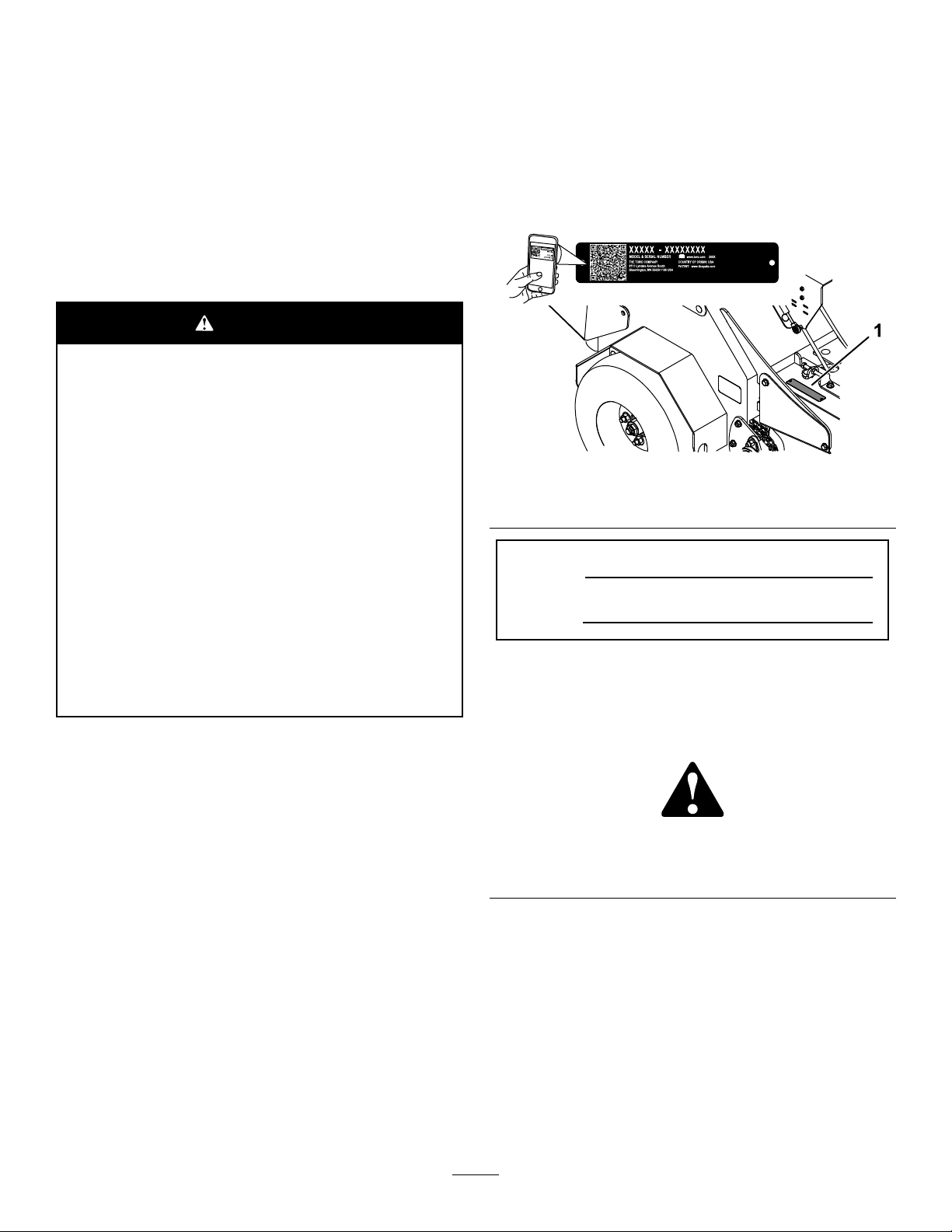
DealerorToroCustomerServiceandhavethemodel
andserialnumbersofyourproductready.Figure1
identiesthelocationofthemodelandserialnumbers
ontheproduct.Writethenumbersinthespace
provided.
Important:Withyourmobiledevice,youcan
scantheQRcodeontheserialnumberdecal(if
equipped)toaccesswarranty,parts,andother
productinformation.
g269064
Figure1
1.Locationofthemodelandserialnumbers
ModelNo.
SerialNo.
Thismanualidentiespotentialhazardsandhas
safetymessagesidentiedbythesafety-alertsymbol
(Figure2),whichsignalsahazardthatmaycause
seriousinjuryordeathifyoudonotfollowthe
recommendedprecautions.
Introduction
Thisaeratorisintendedtobeusedbytrained
operatorsinresidentialandcommercialapplications.
Itisprimarilydesignedforaeratingareasof
well-maintainedlawnsonresidentialgrounds,parks,
sportselds,andoncommercialgrounds.
Readthisinformationcarefullytolearnhowtooperate
andmaintainyourproductproperlyandtoavoid
injuryandproductdamage.Youareresponsiblefor
operatingtheproductproperlyandsafely .
Visitwww.Toro.comforproductsafetyandoperation
trainingmaterials,accessoryinformation,helpnding
adealer,ortoregisteryourproduct.
Wheneveryouneedservice,genuineToroparts,or
additionalinformation,contactanAuthorizedService
©2020—TheToro®Company
8111LyndaleAvenueSouth
Bloomington,MN55420
Figure2
Safety-alertsymbol
Thismanualuses2wordstohighlightinformation.
Importantcallsattentiontospecialmechanical
informationandNoteemphasizesgeneralinformation
worthyofspecialattention.
2
g000502
Contactusatwww.Toro.com.
PrintedintheUSA
AllRightsReserved

Contents
Safety.......................................................................4
SafetyAlertSymbol............................................4
GeneralSafety...................................................4
SafetyandInstructionalDecals..........................4
Setup........................................................................9
1CheckingTireAirPressure..............................9
2ServicingtheBattery........................................9
3ServicingtheEngineOil.................................10
4ServicingtheTransmissionFluid....................10
5ServicingtheAuxiliaryHydraulic
Fluid..............................................................10
ProductOverview....................................................11
Controls............................................................11
Specications..................................................15
Attachments/Accessories.................................15
BeforeOperation.................................................15
BeforeOperationSafety...................................15
FuelSafety.......................................................16
AddingFuel......................................................17
PerformingDailyMaintenance..........................18
DuringOperation.................................................18
DuringOperationSafety...................................18
UsingtheSmartController/ElectronicDepth
Control..........................................................20
OperatingtheMachine.....................................23
AfterOperation....................................................26
AfterOperationSafety......................................26
TransportingtheMachine.................................26
Maintenance...........................................................29
MaintenanceSafetyInformation.......................29
RecommendedMaintenanceSchedule(s)...........31
Pre-MaintenanceProcedures..............................32
PreparingfortheMachinefor
Maintenance.................................................32
AccessingtheConsoleCompartment...............32
Lubrication..........................................................33
LubricatingtheGreaseFittings.........................33
LubricatingtheChains......................................33
LubricatingtheCasters.....................................34
EngineMaintenance...........................................36
ServicingtheAirCleaner..................................36
ServicingtheEngineOil....................................37
ServicingtheSparkPlug...................................40
CheckingtheSparkArrester.............................41
FuelSystemMaintenance...................................41
ServicingtheFuelFilter....................................41
ElectricalSystemMaintenance...........................42
CheckingtheSafety-InterlockSystem..............42
ServicingtheBattery.........................................43
ServicingtheFuses..........................................46
DriveSystemMaintenance..................................46
CheckingtheAirPressureintheTires...............46
CheckingtheWheelHubNuts..........................46
CheckingtheT orqueoftheWheelLug
Nuts..............................................................47
CheckingtheT orqueoftheTransmission
OutputShaftNut...........................................47
AdjustingtheCasterPivotBearings
Pre-Load.......................................................47
BrakeMaintenance.............................................48
AdjustingtheParkingBrake..............................48
AdjustingtheBrakeSwitch...............................48
BeltMaintenance................................................49
CheckingtheConditionandT ensionofthe
Belts..............................................................49
AdjustingtheAuxiliaryPump-Drive
Belt................................................................49
ReplacingtheTransmission-DriveBelt.............49
ControlsSystemMaintenance.............................50
AdjustingtheTraction-ControlLinkage.............50
HydraulicSystemMaintenance...........................51
MaintainingtheAuxiliaryHydraulic
System..........................................................51
MaintainingtheTransmission...........................53
ChainMaintenance..............................................56
CheckingtheConditionoftheSprockets...........56
CheckingtheConditionandT ensionofthe
Chains...........................................................56
AdjustingtheJackshaftDrive-Chain
Tension.........................................................56
AdjustingtheDriveWheelChain
Tension.........................................................57
AdjustingtheTineDriveChain..........................58
TineMaintenance.................................................58
CheckingtheTines...........................................58
ChassisMaintenance...........................................59
CheckingforLooseHardware...........................59
Cleaning..............................................................60
CleaningtheEngineandtheExhaust
SystemArea.................................................60
RemovingtheEngineShroudsandCleaning
theCoolingFins............................................60
CleaningtheDebrisfromtheMachine...............60
WasteDisposal.................................................61
Storage...................................................................61
PreparingtheMachineforStorage...................61
Troubleshooting......................................................62
AlertandErrorMessages.................................62
Schematics.............................................................65
3

Safety
SafetyAlertSymbol
ThisSafetyAlertSymbol(Figure3)isusedbothin
thismanualandonthemachinetoidentifyimportant
safetymessageswhichmustbefollowedtoavoid
accidents.
Thissymbolmeans:ATTENTION!BECOMEALERT!
YOURSAFETYISINVOL VED!
Figure3
SafetyAlertSymbol
Thesafetyalertsymbolappearsaboveinformation
whichalertsyoutounsafeactionsorsituationsand
willbefollowedbythewordDANGER,WARNING,or
CAUTION.
DANGER:Indicatesanimminentlyhazardous
situationwhich,ifnotavoided,Willresultindeathor
seriousinjury.
WARNING:Indicatesapotentiallyhazardoussituation
which,ifnotavoided,Couldresultindeathorserious
injury.
CAUTION:Indicatesapotentiallyhazardoussituation
which,ifnotavoided,Mayresultinminorormoderate
injury.
Thismanualusestwootherwordstohighlight
information.Importantcallsattentiontospecial
mechanicalinformationandNoteemphasizesgeneral
informationworthyofspecialattention.
GeneralSafety
Thismachineiscapableofamputatinghandsandfeet
andofthrowingobjects.Torodesignsandteststhis
machinetoofferreasonablysafeservice;however,
failuretocomplywithsafetyinstructionsmayresultin
injuryordeath.
•Read,understand,andfollowallinstructionsand
warningsintheOperator’sManualandother
trainingmaterial,onthemachine,engine,and
attachments.Alloperatorsandmechanicsshould
betrained.Iftheoperator(s)ormechanic(s)can
notreadthismanual,itistheowner’sresponsibility
toexplainthismaterialtothem;otherlanguages
g000502
maybeavailableonourwebsite.
•Onlyallowtrained,responsible,andphysically
capableoperatorsthatarefamiliarwiththesafe
operation,operatorcontrols,andsafetysignsand
instructionstooperatethemachine.Neverlet
childrenoruntrainedpeopleoperateorservicethe
equipment.Localregulationsmayrestricttheage
oftheoperator.
•DoNotoperatethemachineneardrop-offs,
ditches,embankments,water,orotherhazards.
•DoNotputyourhandsorfeetnearmoving
componentsofthemachine.
•Neveroperatethemachinewithdamagedguards,
shields,orcovers.Alwayshavesafetyshields,
guards,switchesandotherdevicesinplaceandin
properworkingcondition.
•Stopthemachine,shutofftheengine,andremove
thekeybeforeservicing,fueling,orunclogging
themachine.
SafetyandInstructionalDecals
Safetydecalsandinstructionsareeasilyvisibletotheoperatorandarelocatednearanyarea
ofpotentialdanger.Replaceanydecalthatisdamagedormissing.
115-2047
1.Warning—donottouchthehotsurface.
decal115-2047
4
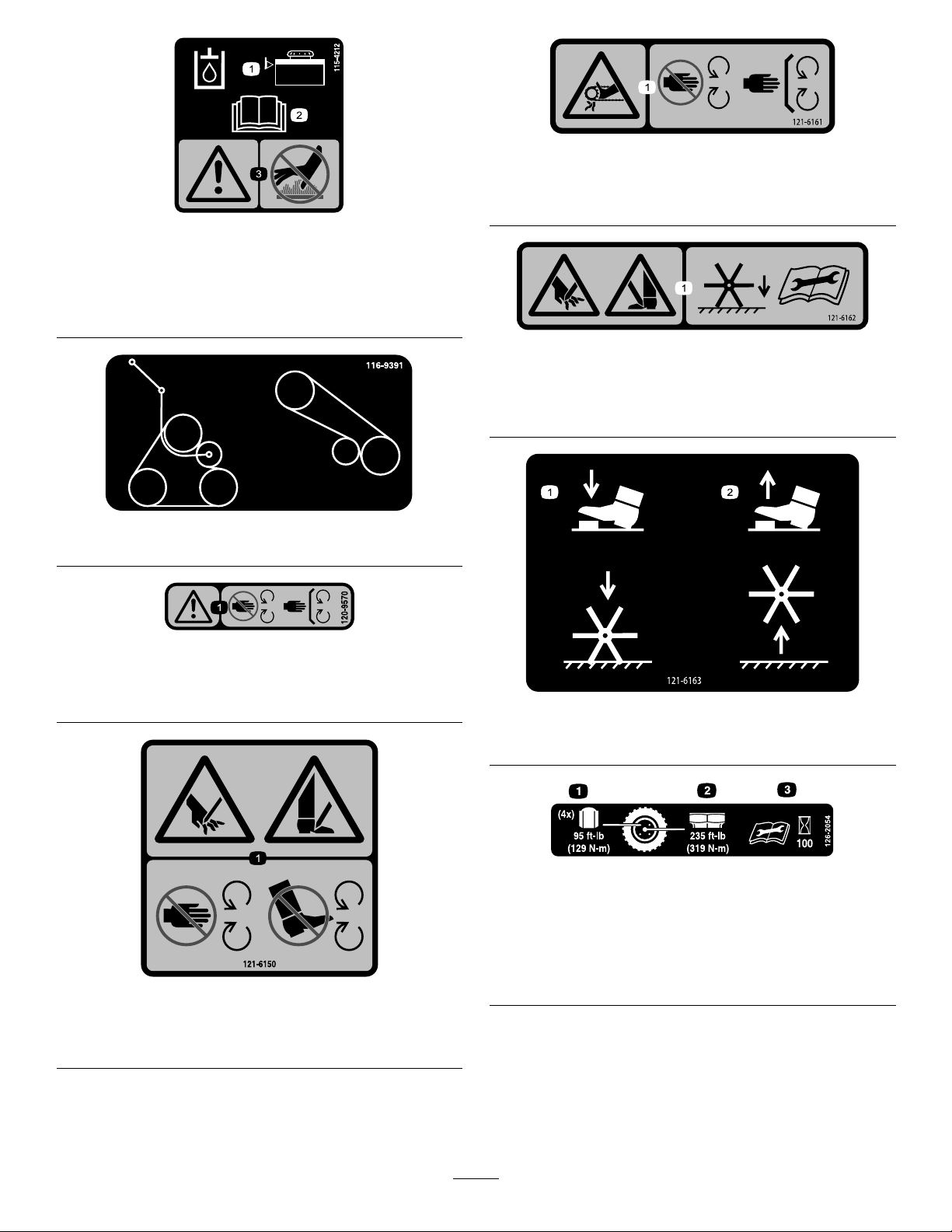
decal121-6161
121-6161
1.Entanglementhazard,belt—stayawayfrommovingparts;
keepallguardsinplace.
decal115-4212
115-4212
1.Hydraulicuidlevel
3.Warning—donottouchthe
hotsurface.
2.ReadtheOperator's
Manual.
116-9391
120-9570
1.Warning—stayawayfrommovingparts;keepallguards
andshieldsinplace.
decal121-6162
121-6162
1.Cutting/dismembermenthazardofhandorfoot—lowerthe
tinestotheground;readtheOperator’sManualforthe
disassemblyprocedure.
decal116-9391
decal120-9570
decal121-6163
121-6163
121-6150
1.Cuttinghazardofhandandfoot—stayawayfrommoving
parts.
1.Presstolowerthetines.2.Releasetoraisethetines.
decal126-2054
126-2054
1.Wheellugnuttorque129N∙m(95ft-lb)(4x)
2.Wheelhubnuttorque319N∙m(235ft-lb)
3.ReadandunderstandtheOperator’sManualbefore
performinganymaintenance;checkthetorqueevery100
decal121-6150
hours.
5
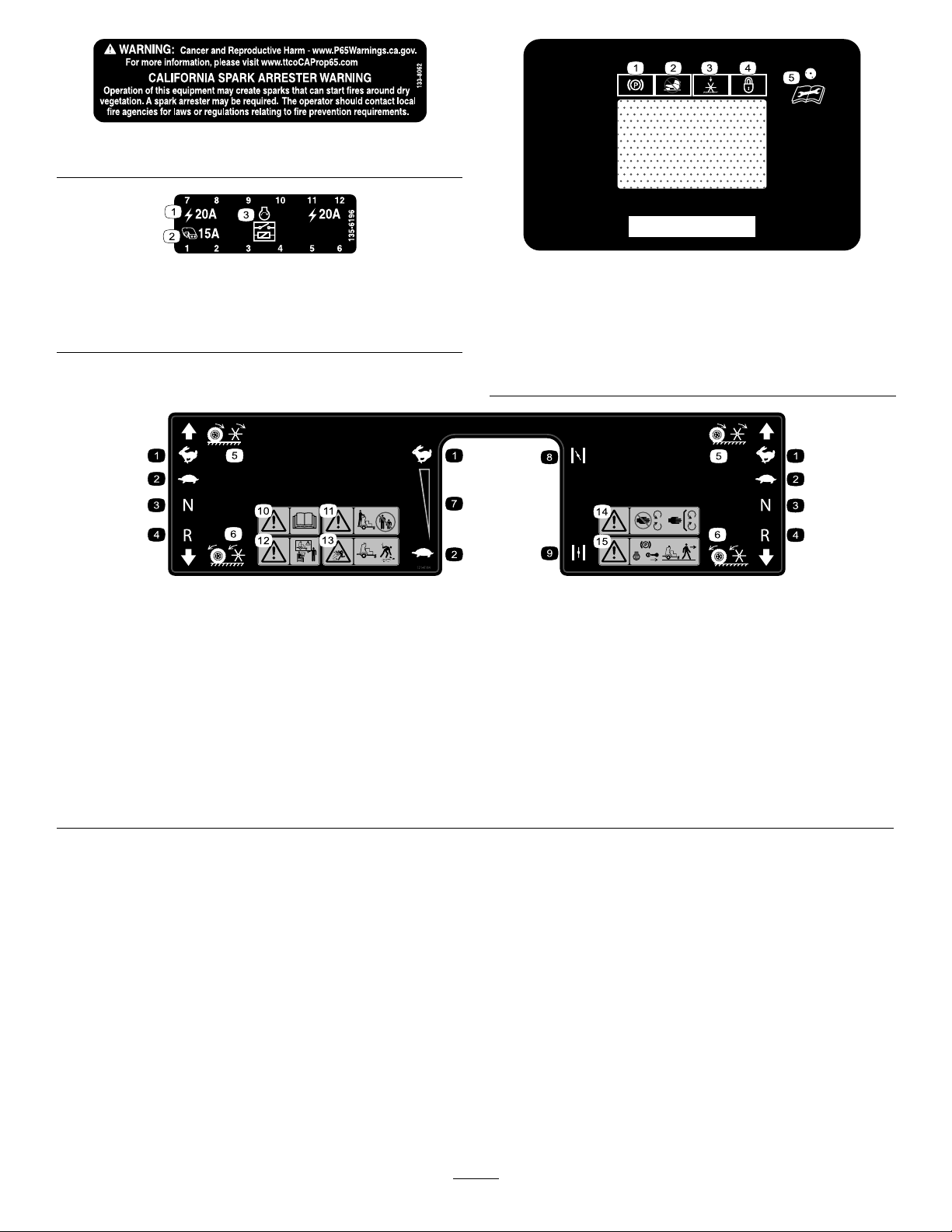
decal133-8062
133-8062
decal135-6196
135-6196
1.Electric3.Enginestartrelay
2.Accessory
1.Parkingbrake4.Depthsetting—lock
2.Tineengagementlockout
3.Tines—down
121-6164
1.Fast6.Wheelsandtinesrotatewhenmoving
2.Slow7.Continuousvariablesetting
3.Neutral
4.Reverse
5.Wheelsandtinesrotatewhenmoving
forward
backward
8.Choke—on
9.Choke—off14.Warning—stayawayfrommoving
10.Warning—readtheOperator’sManual.15.Warning—shutofftheengine,engage
decal135-1854
135-1854
switch
11.Warning—keepbystandersaway .
12.Warning—donotoperatethemachine
unlessyouaretrained.
13.Thrownobjecthazard—pickupdebris
beforeoperatingthemachine.
parts;keepallguardsinplace.
theparkingbreak,andremovethekey
beforeleavingthemachine.
5.ReadtheOperator’s
Manualbeforeperforming
maintenance.
decal121-6164
6

decal135-5948
135-5948
1.Rotatecounterclockwisetodecreasepressure.
2.Rotateclockwisetoincreasepressure.
3.Pressandholdfor1secondtoturnon—tineground
engagementfootswitchunlock
4.Electronictinedepth—decrease
5.Electronictinedepth—increase12.Parkingbrake—disengage
6.Pressandholdfor1secondtoturnoff—tineground
engagementfootswitchlock
7.Cutting/dismembermenthazardofhandorfoot,tines–stay
awayfrommovingparts;keepallguardsinplace.
8.Tippinghazard—Donotturnsharplywhiletravelingfast;slow
downandturngradually.Donotoperatethemachinenear
drop-offs.Donotusesplitramps;usefullwidthrampstoload
amachinefortransport.
9.Engine—Off
10.Engine—On
11.Engine—Start
13.Parkingbrake—engage
7
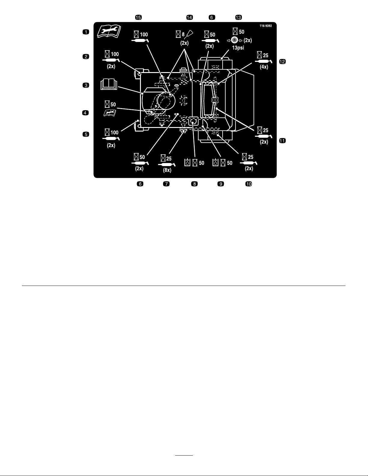
decal116-9392
116-9392
1.ReadandunderstandtheOperator’sManualbeforeservicing
9.Checktheauxiliaryhydraulictankevery50hours.
thismachine.
2.Greasethefrontcasterpivots(2x)every100hours.10.Greasethewheelbearings(2x)every25hours.
3.Refertotheengineowner’smanualforservice.11.Greasethetineassemblyidlers(2x)every25hours.
4.Checktheauxiliarypump-drivebelttensionevery50hours.12.Greasethetineshaftbearings(4x)every25hours.
5.Greasethefrontcasterwheelbearings(2x)every100hours.13.Checkthetirepressure,13psi,(2x)every50hours.
6.Greasethecontrolpivots(4x)every50hours.14.Cleanandoilthechainsandcheckthechaintension(2x)
every8hours.
7.Greasethejackshaftbearings(8x)every25hours.15.Greasethebeltidlerpivotevery100hours.
8.Checkthehydraulic-uidlevel(2x)every50hours.
8

Setup
MediaandAdditionalParts
Description
Operator'sManual
Key2
1
CheckingTireAirPressure
NoPartsRequired
Procedure
Checktheairpressureinthedrivetires,andadjust
thepressureasneeded;refertoCheckingtheAir
PressureintheTires(page46).
Note:Youdonotadjustairpressureforthe
semi-pneumaticcastertires.
2
ServicingtheBattery
NoPartsRequired
Procedure
Qty.
Use
1
Readbeforeoperatingthemachine.
Startthemachine.
BatteryChargeTable
Voltage
Reading
12.6or
greater
12.4to12.6
12.2to12.4
12.0to12.2
11.7to12.0
11.7orless
4.Ifthepositivecableisalsodisconnected,
connectthepositive(red)cabletothepositive
batteryterminalandsliptheterminalcoverover
thepositiveterminal.
5.Removethescrew,washer,andgroundcable
fromtheengine.Connectthenegativebattery
cableasshowninFigure4.
Percent
Charge
100%
75to100%
50to75%
25to50%
0to25%
0%
Maximum
Charger
Settings
16V/
7A
16V/
7A
16V/
7A
14.4V/
4A
14.4V/
4A
14.4V/
2A
Charging
Interval
Nocharging
required
30minutes
1hour
2hours
3hours
6hoursor
more
Note:Themachineisshippedwithalled,lead-acid
battery.
1.MovethekeyswitchtotheOFFpositionand
removethekey.
2.Measurethevoltageofthebatterywitha
voltmeter.
3.Usethetablethatfollowstolocatethe
chargestateorthebattery,andifneeded,the
battery-chargersettingandcharginginterval
recommendedtochargethebatteryto12.6Vor
greater;refertothebatterychargetablebelow.
Important:Makesurethatthenegative
batterycableisdisconnected,andthe
batterychargerusedforchargingthebattery
hasanoutputof16Vand7Aorlessto
avoiddamagingthebattery(seechartfor
recommendedchargersettings).
9
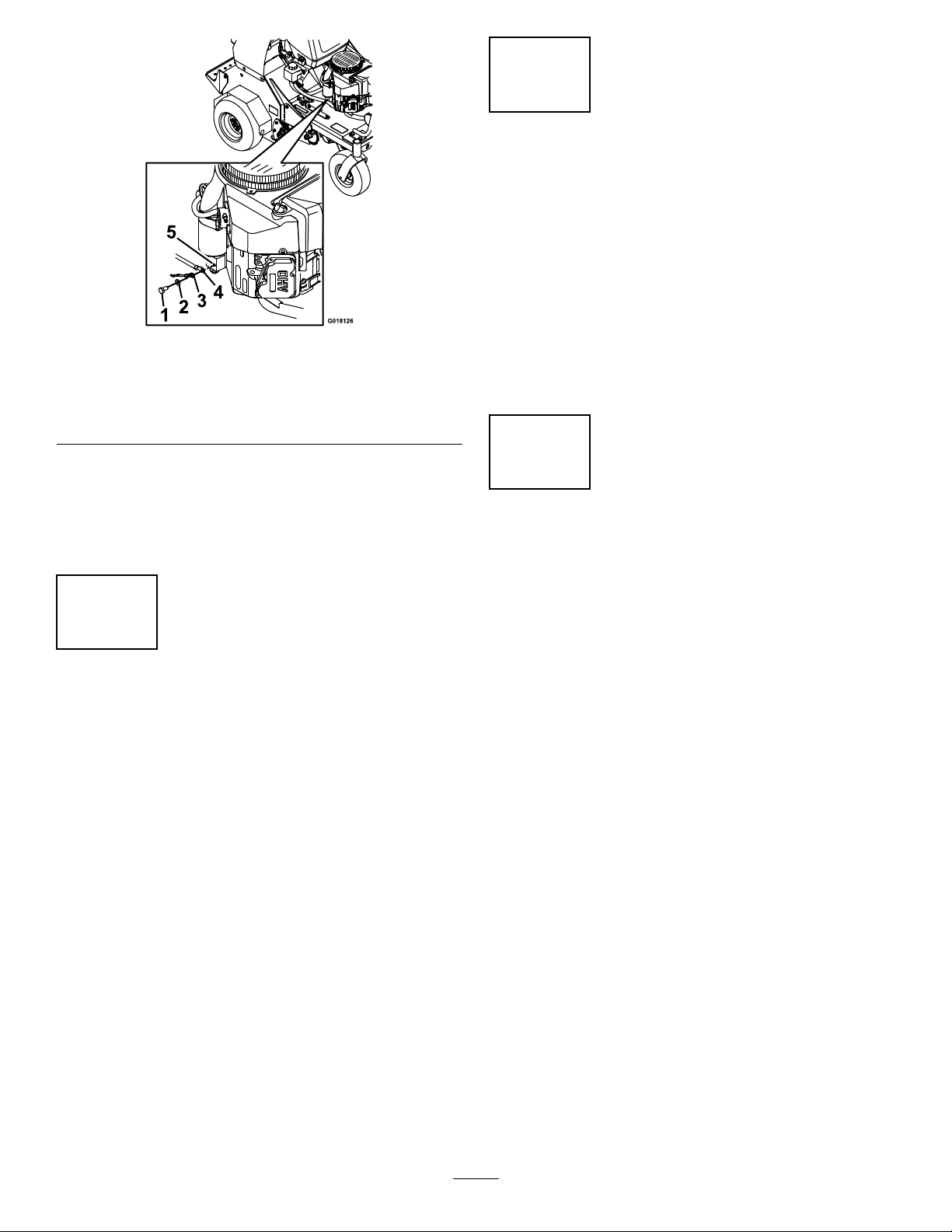
Figure4
1.Screw
2.Washer5.Engine
3.Groundwire
4.Negativebatterycable
4
ServicingtheTransmission
Fluid
NoPartsRequired
Procedure
Themachineisshippedwithtransmissionuid;check
g018126
thetransmission-uidleveland,ifnecessary,add
uidtotheappropriatelevel.RefertoCheckingthe
TransmissionFluidLevel(page53)forinstructions
andtheoilspecication.
Note:Iftimedoesnotpermitchargingthe
batteryorifchargingequipmentisnotavailable,
connectthenegativebatterycablesandrun
thevehiclecontinuouslyfor20to30minutesto
chargethebattery.
3
ServicingtheEngineOil
NoPartsRequired
Procedure
Theengineisshippedwithoil;checktheengine-oil
leveland,ifnecessary,addoiltotheappropriatelevel.
RefertoCheckingtheEngine-OilLevel(page37)for
instructionsandtheoilspecication.
5
ServicingtheAuxiliary
HydraulicFluid
NoPartsRequired
Procedure
Themachineisshippedwithhydraulicuid;check
thehydraulic-uidleveland,ifnecessary,adduidto
theappropriatelevel.RefertoCheckingtheAuxiliary
Hydraulic-FluidLevel(page51)forinstructionsand
theoilspecication.
10
ProductOverview
g267503
Figure6
Figure5
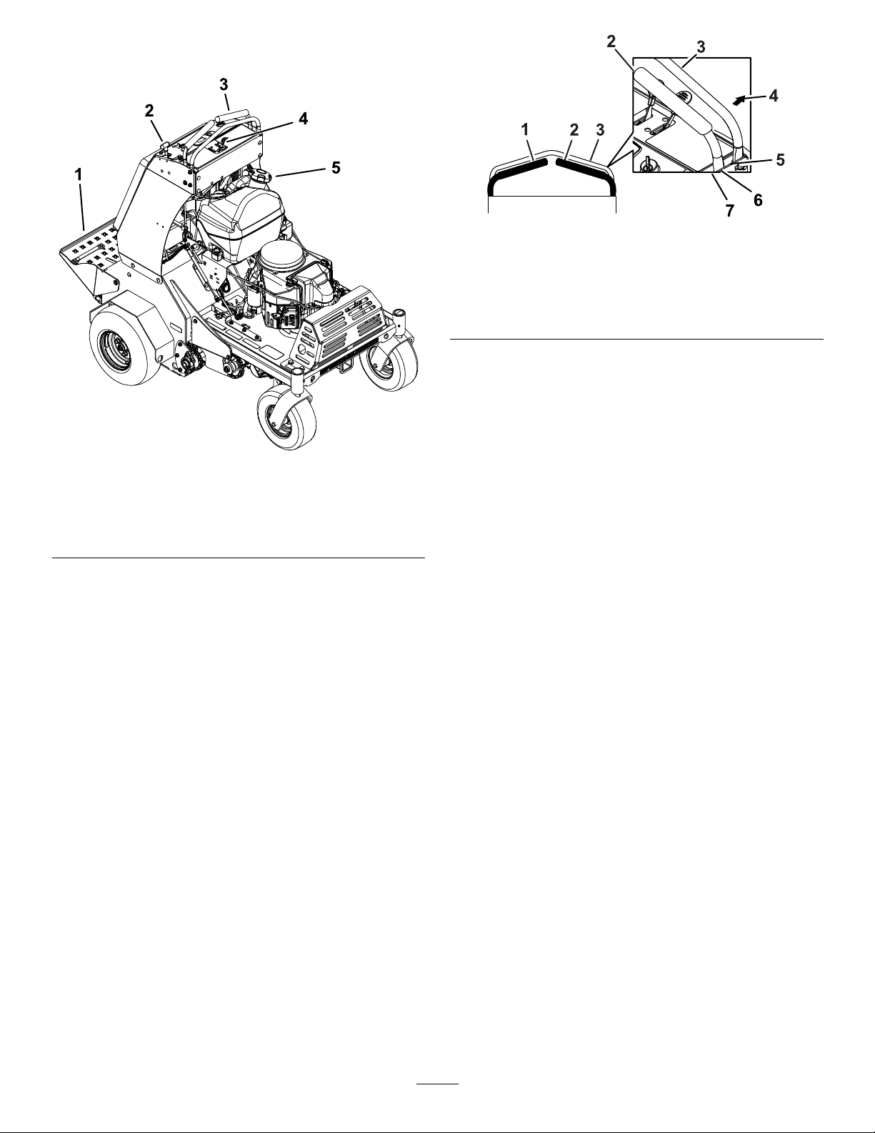
1.Platform
2.Parking-brakeknob5.Fuelcap
3.Motion-controllevers
4.Enginecontrols
Controls
Motion-ControlLevers
Themotion-controlleversarelocatedoneachsideof
thetopconsoleandcontroltheforwardandreverse
motionofthemachine.
Movetheleversforwardorbackwardtocontrolthe
drivewheelonthesamesideforwardorreverse
respectively.Thewheelspeedisproportionaltothe
amountyoumovethelever.
Important:Thetinesrotatewhenthe
motion-controlleversaremovedoutofthe
NEUTRALposition.
1.Leftmotion-controllever
2.Rightmotion-controllever6.Neutral
3.Frontreferencebar
4.Frontofthemachine
5.Forward
7.Reverse
ThrottleLever
Thethrottlelever(Figure7)islocatedonthecontrol
console(redlever).
g269241
Usethethrottlelevertocontrolenginespeed.Move
thethrottleleverforwardtoincreaseenginespeed;
movingthethrottleleverrearwardtodecreasethe
enginespeed.
Note:Movethethrottleleverforwardintothedetent
forfullthrottle.
ChokeLever
Thechokelever(Figure7)islocatedonthecontrol
console(blacklever).
Usethechokeleverisusedtoaidinstartingacold
engine.Movethechokeleverforwardtosetthe
choketotheONposition;movethechokelevertothe
rearwardtoreducethechoke.
Note:Pullthechokeleverbackintothedetenttoset
thechoketotheOFFposition.
Note:Donotrunawarmenginewiththechokein
theONposition.
11

1.Hour
meter/tine-engagement
display
2.Operatorweight
adjustmentcontrol
3.Multi-functionswitch
4.Leftmotion-controllever
5.Frontreferencebar
6.Throttlelever
Parking-BrakeHandle
Figure7
7.Chokelever
8.Rightmotion-controllever
9.Ignitionswitch
10.Parking-brakehandle
11.Tineground-engagement
footswitch
HourMeter/TineEngagement
Display
Locatedtotheleftoftheignitionswitchonthecontrol
console.
•Thehourmetermonitorsanddisplaystheengine
hours.
g211730
Figure8
g267524
1.LCDIndicators/Informationscreen
2.Hourdisplay
3.LEDstatuslight
Hoursaredisplayedwhenthekeyisofforwhen
themachineisrunning.Hoursarenotdisplayed
whenthemachineisaerating.
Note:TheLCDindicatorappearsinthepark
brakesettingwhenitmeetsthe“safetostart”
mode(parkingbrakeengaged).
•Thetine-engagementdisplaymonitorsand
displaystheelectronictine-depthsetting.
Hourmeterdisplay
Theparking-brakehandleislocatedonthecontrol
console,totherightofthekeyswitch(Figure7).
Note:Thebrakehandleengagesaparkingbrakein
eachofthetransmissions.
•T oengagetheparkingbrake,pullthehandleout
andslideitrearward.
•T oreleasetheparkingbrake,pushthehandle
forwardintothedetent.
Whenparkingonasteepslope,chockorblockthe
wheelsinadditiontoengagingtheparkingbrake.Tie
downthemachineandengagetheparkingbrake
whentransportingthemachine.
g211731
Figure9
Tine-engagementdisplay
1.LCDIndicators/Informationscreen
2.Tinedepthstatusbar
3.Tinedepthsettingindicator
4.LEDstatuslight
12

Thereare2waystoactivatethedisplay:
1.T apthemulti-functionswitcheitherupordown
todisplaythetine-engagementmeter.
2.Steponthetineground-engagementfootswitch.
Ahighernumberonthestatusbarincreasesthe
lengthoftheaerationplugandalowernumber
decreasesit.
Note:Ifthepluglengthisnotdesiredlength,the
machinemayneedtobeadjustedtoaccommodate
fortheweightoftheoperator;refertoAdjustingthe
OperatorWeightControlSetting(page24)formore
information.
KeySwitch
Thekeyswitchislocatedontherightsideofthe
controlconsole(Figure7).
Usethekeyswitchtostartandshutofftheengine.
Theswitchhas3positions:OFF,ON,andSTART
(Figure10).
LEDStatusLights
Locatedontherightsideofthehour
meter/tine-engagementdisplay.
TheLEDismulti-coloredtoindicatethesystemstatus
andislocatedontherightsideofthepanel.
•Solidgreen—indicatesnormaloperatingactivity.
•Blinkingred—indicatesafaultisactive.
•Solidred—indicatesmaintenanceisrequired.
TinesGround-EngagementFoot
Switch
Theswitchislocatedontheoperatorplatform(Figure
7).
Tolowerthetinesintotheground,standonthetine
ground-engagementswitch.TheLEDilluminatesin
thehourmeter/tineengagementdisplaywhenthetine
engagementisactivated.T oraisethetines,remove
yourfootfromtheswitch.
Thisswitchcanbedisabledwiththemulti-function
switch.
g008610
Figure10
1.OFF3.START
2.ON
Multi-FunctionSwitch
Locatedtotheleftofthehourmeter/tine-engagement
display.
Thisswitchallowsyoutodothefollowing:
•Increase/decreasethedepthofanaerationplug.
•Lockorunlockthetine-depthsetting.
•Lockorunlockthetineground-engagementfoot
switch.
•T apandholdthebottomoftheswitchtooverride
anddisablethefootswitch.TheLEDilluminatesin
thehourmeter/tineengagementdisplay.Usethis
featurewhentransportingthemachine.
•T ounlock,tapandholdthetopofthemulti-function
switchuntiltheLEDlightdisappears.
Note:Thedisablefeatureisengagedeachtimeyou
shutofftheengine.
13
Fuel-ShutoffValve
Thefuel-shutoffvalveislocatedbehindtheengine
andunderthefueltank(Figure11).
Usethefuel-shutoffvalvetoshutoffthefuelwhen
themachinewillnotbeusedforafewdays,when
transportingthemachinetoandfromthejobsite,or
whenthemachineisparkedinsideabuilding.
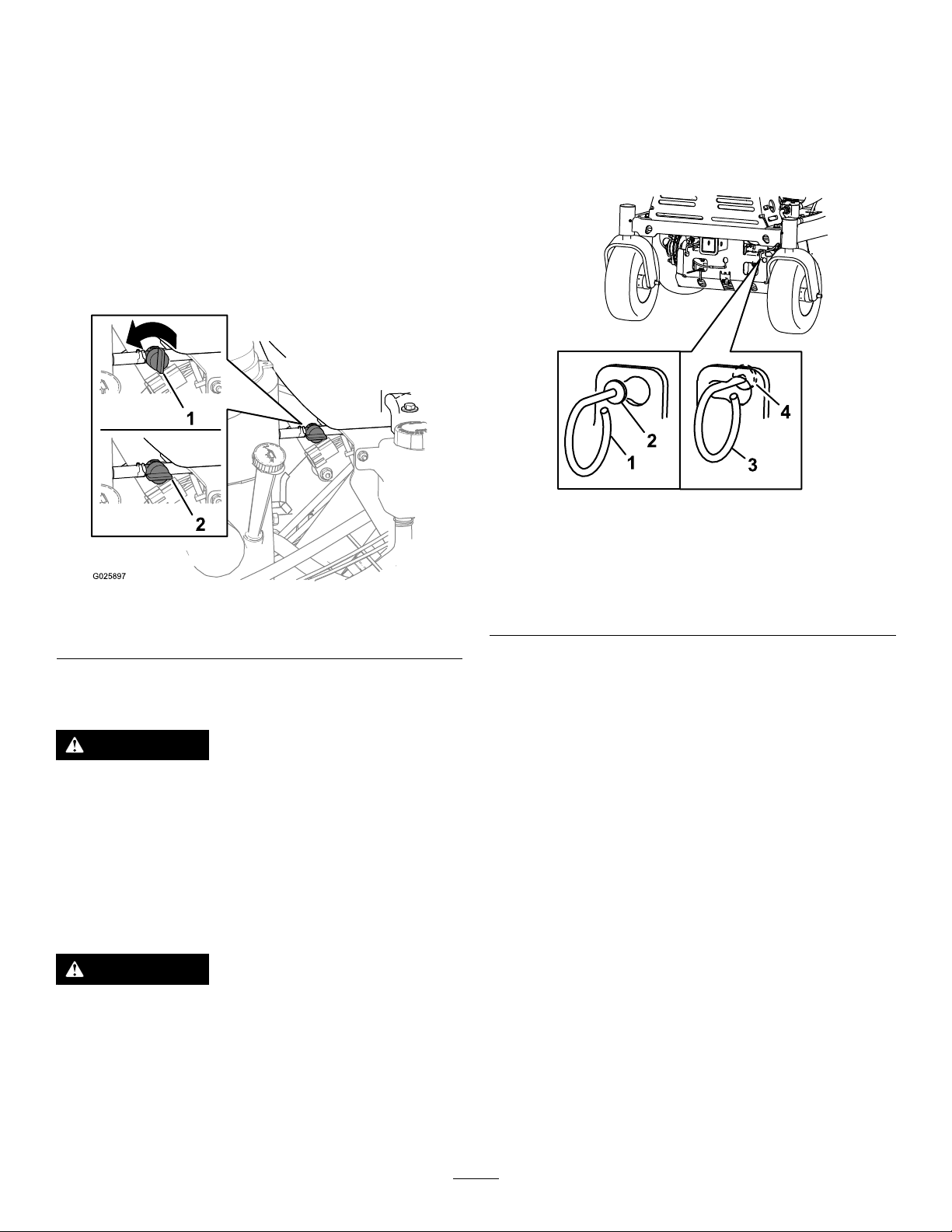
•T oopenforfuel-shutoffvalve,rotatethehandle
ofthefuel-shutoffvalveuntilitisalignedwiththe
fuelline.
•T oclosethefuel-shutoffvalve,rotatethehandle
90°tothefuelline.
Locatedontheleftandrightsidesunderneaththe
frontofthemachine.
Duringnormaloperatingconditions,thewasheron
theleverispositionedoutsidetheslots.Ifyouneed
topushthemachinebyhand,youmustpositionthe
leverforthedrivewheelreleasevalvetothevalve
releasedposition(Figure12).
g223057
Figure12
Figure11
1.OFFposition2.ONposition
Drive-WheelReleaseValves
WARNING
Yourhandsmaybecomeentangledinthe
rotatingdrivecomponentsbelowtheengine
deck,whichcouldresultinseriousinjuryor
death.
Shutofftheengine,removethekey,andallow
allmovingpartstostopbeforeaccessingthe
drive-wheelreleasevalves.
WARNING
1.Lever—drivewheel
releasevalve(normal
g025897
operatingposition)
2.Washeroutsideoftheslot
3.Lever—drivewheel
releasevalve(pushthe
machineposition)
4.Washerinsidetheslot
(valvereleasedposition)
Toreleasethedrivewheels,movethelevertothe
largeropeningoftheslot,pushitinuntilthewasher
isinsidetheframe,thenmovetheleverbacktothe
narrowportionoftheslot.Repeatthisoneachside
ofthemachine.
Disengagetheparkingbrake.Themachineisnow
abletobepushedbyhand.
Donottowmachine.
Toresetthedrivesystembacktotheoperating
position:
Movethelevertothelargeropeningoftheslot,pull
outwarduntilthewasherisoutsidetheframe,then
movetheleverbacktothenarrowportionoftheslot.
Repeatthisoneachsideofthemachine.
Theengineandhydrauliccomponentscan
becomeveryhot.Touchingahotengine
orhydrauliccomponentscancausesevere
burns.
Allowtheengineandhydrauliccomponents
tocoolcompletelybeforeaccessingthe
drive-wheelreleasevalves.
14

Specications
Height
Length
Width
Aerationwidth
Coringrange5.1to12.7cm(2to5inches)
Weight
Attachments/Accessories
AselectionofT oroapprovedattachmentsand
accessoriesisavailableforusewiththemachine
toenhanceandexpanditscapabilities.Contact
yourAuthorizedServiceDealerorauthorizedT oro
distributororgotowww.Toro.comforalistofall
approvedattachmentsandaccessories.
Toensureoptimumperformanceandcontinuedsafety
certicationofthemachine,useonlygenuineT oro
replacementpartsandaccessories.Replacement
partsandaccessoriesmadebyothermanufacturers
couldbedangerous,andsuchusecouldvoidthe
productwarranty.
132cm(52inches)
163cm(64inches)
121cm(48inches)
76cm(30inches)
460kg(1,015lb)
Operation
BeforeOperation
BeforeOperationSafety
•Evaluatetheterraintodeterminewhataccessories
andattachmentsareneededtoproperlyand
safelyperformthejob.Onlyuseaccessoriesand
attachmentsapprovedbyToro.
•Inspecttheareawheretheequipmentistobe
usedandremoveallrocks,toys,sticks,wires,
bones,andotherforeignobjects.Thesecan
bethrownorinterferewiththeoperationofthe
machineandmaycausepersonalinjurytothe
operatororbystanders.
•Markandavoidhiddenobjectssuchassprinkler
heads,undergroundwires/cables,invisiblefences,
etc.topreventdamagetothesesystemswhen
aerating.
•Wearappropriatepersonalprotectiveequipment
suchassafetyglasses,substantialslip-resistant
footwear,andhearingprotection.Tiebacklong
hairandavoidlooseclothingandloosejewelry
whichmaygettangledinmovingparts.
CAUTION
Thismachineproducessoundlevelsin
excessof85dBAattheoperator’searand
cancausehearinglossthroughextended
periodsofexposure.
Wearhearingprotectionwhenoperating
thismachine.
•Checkthattheoperatorpresencecontrols,
safetyswitches,andshieldsareattachedand
functioningproperly.DoNotoperateunlessthey
arefunctioningproperly.
•DoNotoperatethemachinewhenpeople,
especiallychildren,orpetsareinthearea.Stop
themachineandattachment(s)ifanyoneenters
thearea.
•DoNotoperatethemachinewithdamagedguards,
shields,orcovers.Alwayshavesafetyshields,
guards,switchesandotherdevicesinplaceand
inproperworkingcondition.Frequentlycheckfor
wornordeterioratingcomponentsandreplace
themwiththemanufacturer’srecommendedparts
whennecessary.
15

FuelSafety
DANGER
Useextremecarewhenhandlingfuel.
DANGER
Incertainconditionsgasolineisextremely
ammableandvaporsareexplosive.
Areorexplosionfromgasolinecanburn
you,others,andcausepropertydamage.
•Fillthefueltankoutdoorsonlevelground,
inanopenarea,whentheengineiscold.
Wipeupanygasolinethatspills.
•Neverrellthefueltankordrainthe
machineindoorsorinsideanenclosed
trailer.
•DoNotllthefueltankcompletelyfull.
Fillthefueltanktothebottomoftheller
neck.Theemptyspaceinthetankallows
gasolinetoexpand.Overllingmayresult
infuelleakageordamagetotheengineor
emissionsystem.
•Neversmokewhenhandlinggasoline,and
stayawayfromanopenameorwhere
gasolinefumesmaybeignitedbyspark.
•Storegasolineinanapprovedcontainer
andkeepitoutofthereachofchildren.
Incertainconditionsduringfueling,static
electricitycanbereleasedcausingaspark
whichcanignitegasolinevapors.Areor
explosionfromgasolinecanburnyouand
othersandcausepropertydamage.
•Alwaysplacegasolinecontainersonthe
groundawayfromyourvehiclebefore
lling.
•DoNotllgasolinecontainersinsidea
vehicleoronatruckortrailerbedbecause
interiorcarpetsorplastictruckbedliners
mayinsulatethecontainerandslowthe
lossofanystaticcharge.
•Whenpractical,removegas-powered
equipmentfromthetruckortrailerand
refueltheequipmentwithitswheelsonthe
ground.
•Ifthisisnotpossible,thenrefuelsuch
equipmentonatruckortrailerfroma
portablecontainer,ratherthanfroma
gasolinedispensernozzle.
•Ifagasolinedispensernozzlemustbe
used,keepthenozzleincontactwiththe
rimofthefueltankorcontaineropeningat
alltimesuntilfuelingiscomplete.DoNot
useanozzlelockopendevice.
•Addfuelbeforestartingtheengine.Never
removethecapofthefueltankoraddfuel
whenengineisrunningorwhentheengine
ishot.
•Iffuelisspilled,DoNotattempttostart
theengine.Moveawayfromtheareaof
thespillandavoidcreatinganysourceof
ignitionuntilfuelvaporshavedissipated.
•DoNotoperatewithoutentireexhaust
systeminplaceandinproperworking
condition.
WARNING
Gasolineisharmfulorfatalifswallowed.
Long-termexposuretovaporshascaused
cancerinlaboratoryanimals.Failuretouse
cautionmaycauseseriousinjuryorillness.
•Avoidprolongedbreathingofvapors.
•Keepfaceawayfromnozzleandgas
tank/containeropening.
•Keepawayfromeyesandskin.
•Neversiphonbymouth.
Tohelppreventres:
•Keepengineandengineareafreefrom
accumulationofgrass,leaves,excessivegrease
oroil,andotherdebriswhichcanaccumulatein
theseareas.
•Cleanupoilandfuelspillsandremovefuelsoaked
debris.
•Allowthemachinetocoolbeforestoringthe
machineinanyenclosure.DoNotstorenear
ameoranyenclosedareawhereopenpilotlights
orheatappliancesarepresent.
16

AddingFuel
DANGER
Incertainconditions,fuelisextremely
ammableandhighlyexplosive.Areor
explosionfromfuelcanburnyouandothers
andcandamageproperty.
•Fillthefueltankoutdoors,inanopenarea,
andwhentheengineiscold.Wipeupany
fuelthatspills.
WARNING
Fuelisharmfulorfatalifswallowed.
Long-termexposuretovaporscancause
seriousinjuryandillness.
•Avoidprolongedbreathingofvapors.
•Keepyourfaceawayfromthenozzleand
fueltankorconditionerbottleopening.
•Avoidcontactwithskin;washoffspills
withsoapandwater.
•Donotllthefueltankcompletelyfull.
Addfueltothefueltankuntilthelevelis6
to13mm(1/4to1/2inch)belowthebottom
ofthellerneck.Thisemptyspaceinthe
tankallowsthefueltoexpand.
•Neversmokewhenhandlingfuel,andstay
awayfromanopenameorwhereaspark
mayignitethefuelfumes.
•Storefuelinanapprovedfuelcontainer
andkeepitoutofthereachofchildren.
•Neverbuymorethana30-daysupplyof
fuel.
DANGER
Incertainconditionsduringfueling,static
electricitycanbereleased,causingaspark,
whichcanignitethefuelvapors.Areor
explosionfromfuelcanburnyouandothers
andcandamageproperty.
•Alwaysplacefuelcontainersontheground
awayfromyourvehiclebeforelling.
•Donotllfuelcontainersinsideavehicle
oronatruckortrailerbedbecauseinterior
carpetsorplastictruckbedlinersmay
insulatethecontainerandslowthelossof
anystaticcharge.
•Whenpractical,removefuel-powered
equipmentfromthetruckortrailerand
refueltheequipmentwithitswheelsonthe
ground.
FuelSpecication
Petroleum
fuel
Ethanol
blended
fuel
Important:Forbestresults,useonlyclean,fresh
fuel(lessthan30daysold).
•Donotusegasolinecontainingmethanol.
•Donotstorefueleitherinthefueltankorfuel
containersoverthewinterunlessyouuseafuel
stabilizer.
•Donotaddoiltogasoline.
Useunleadedgasolinewithanoctaneratingof87
orhigher((R+M)/2ratingmethod).
Useanunleaded-gasolineblendwithupto10%
ethanol(gasohol)or15%MTBE(methyltertiary
butylether)byvolumeisacceptable.Ethanoland
MTBEarenotthesame.
Gasolinewith15%ethanol(E15)byvolumeis
notapprovedforuse.Neverusegasolinethat
containsmorethan10%ethanolbyvolume,such
asE15(contains15%ethanol),E20(contains
20%ethanol),orE85(containsupto85%
ethanol).Usingunapprovedgasolinemaycause
performanceproblemsand/orenginedamage
whichmaynotbecoveredunderwarranty.
UsingStabilizer/Conditioner
Alwaysusefuelstabilizer/conditionerinthemachine
tokeepthefuelfreshlonger.
Important:Donotusefueladditivescontaining
methanolorethanol.
Addtheamountoffuelstabilizer/conditionertofresh
fuelasdirectedbythefuel-stabilizermanufacturer.
•Ifthisisnotpossible,thenrefuelsuch
equipmentonatruckortrailerfroma
portablecontainerratherthanfroma
fuel-dispensernozzle.
•Ifyoumustuseafuel-dispensernozzle,
keepthenozzleincontactwiththerimof
thefueltankorcontaineropeningatall
timesuntilfuelingiscomplete.
FuelingtheMachine
Fuel-tankcapacity:18.9L(5USGallons)
1.Cleanaroundthefuel-tankcap.
2.Removethecapfromthetank.
3.Fillthefueltankwithfueltowithin6to13mm
(1/4to1/2inch)fromthetopofthetank.Donot
llintothellerneck.
17

Important:Donotllthetankmorethan
6mm(1/4inch)fromthetopofthetank
becausethefuelmusthaveroomtoexpand.
4.Installthefuel-tankcapandwipeupanyspilled
fuel.
PerformingDaily
WARNING
Engineexhaustcontainscarbonmonoxide,
whichisanodorlessdeadlypoisonthatcan
killyou.
DoNotrunengineindoorsorinasmall
connedareawheredangerouscarbon
monoxidefumescancollect.
Maintenance
Beforestartingthemachineeachday,performeach
use/dailymaintenanceproceduresthatfollow:
•LubricatingtheChains(page33)
•CheckingtheEngine-OilLevel(page37)
•CheckingtheSafety-InterlockSystem(page42)
•CheckingtheConditionoftheSprockets(page56)
•CheckingtheConditionandTensionoftheChains
(page56)
•CheckingtheTines(page58)
•CheckingforLooseHardware(page59)
•CleaningtheEngineandtheExhaustSystem
Area(page60)
•CleaningtheDebrisfromtheMachine(page60)
DuringOperation
Note:Determinetheleftandrightsidesofthe
machinefromthenormaloperatingposition.
•Theowner/usercanpreventandisresponsible
foraccidentsorinjuriesoccurringtohimselfor
herself,otherpeopleorproperty .
•Thismachinewasdesignedforoneoperatoronly.
Donotcarrypassengersandkeepallothersaway
frommachineduringoperation.
•DoNotoperatethemachineundertheinuence
ofalcoholordrugs.
•Operateonlyindaylightorgoodarticiallight.
•Lightningcancausesevereinjuryordeath.If
lightningisseenorthunderisheardinthearea,
DoNotoperatethemachine;seekshelter.
•Useextracarewhileoperatingwithaccessoriesor
attachments.Thesecanchangethestabilityof
themachineandcausealossofcontrol.Follow
directionsforcounterweightsifrequired.
•Keepawayfromholes,ruts,bumps,rocks,and
otherhiddenhazards.Usecarewhenapproaching
blindcorners,shrubs,trees,tallgrassorother
objectsthatmayhideobstaclesorobscurevision.
Uneventerraincouldoverturnthemachineor
causetheoperatortolosetheirbalanceorfooting.
DuringOperationSafety
GeneralSafety
Theoperatormustusetheirfullattentionwhen
operatingthemachine.DoNotengageinanyactivity
thatcausesdistractions;otherwise,injuryorproperty
damagemayoccur.
WARNING
Operatingengineparts,especiallythemufer,
becomeextremelyhot.Severeburnscan
occuroncontactanddebris,suchasleaves,
grass,brush,etc.cancatchre.
•Allowengineparts,especiallythemufer,
tocoolbeforetouching.
•Removeaccumulateddebrisfrommufer
andenginearea.
•Besurealldrivesareinneutralandparkingbrake
isengagedbeforestartingengine.
•Starttheenginecarefullyaccordingtoinstructions
withfeetwellawayfromthetines.
•Neveroperatethemachinewithdamagedguards,
shields,orcovers.Alwayshavesafetyshields,
guards,switchesandotherdevicesinplaceandin
properworkingcondition.
•Keepclearofthetinesatalltimes.
•Keephandsandfeetawayfrommovingparts.
Ifpossible,DoNotmakeadjustmentswiththe
enginerunning.
18

WARNING
Hands,feet,hair,clothing,oraccessories
canbecomeentangledinrotatingparts.
Contactwiththerotatingpartscan
causetraumaticamputationorsevere
lacerations.
–DoNotoperatethemachinewithout
guards,shields,andsafetydevicesin
placeandworkingproperly.
–Keephands,feet,hair,jewelry,or
clothingawayfromrotatingparts.
•Beawareofthedischargepathanddirect
dischargeawayfromothers.Avoiddischarging
materialagainstawallorobstructionasthe
materialmayricochetbacktowardtheoperator.
Raisethetines,slowdown,andusecautionwhen
crossingsurfacesotherthangrassandwhen
transportingthemachinetoandfromthework
area.
•Bealert,slowdownandusecautionwhenmaking
turns.Lookbehindandtothesidebeforechanging
directions.DoNotoperateinreverseunless
absolutelynecessary.
•DoNotchangetheenginegovernorsettingor
overspeedtheengine.
•Parkthemachineonlevelground.Stopengine,
waitforallmovingpartstostop,andremovethe
sparkplugwire(s).
–Beforechecking,cleaningorworkingonthe
machine.
–Afterstrikingaforeignobjectorabnormal
vibrationoccurs(inspectthemachinefor
damageandmakerepairsbeforerestarting
andoperatingthemachine).
–Beforeclearingblockages.
–Wheneveryouleavethemachine.DoNot
leavearunningmachineunattended.
–Beforeandwhilebackingorchangingdirection,
lookbehind,down,andside-to-sideforsmall
children.
–Neverallowchildrentooperatethemachine.
–DoNotcarrychildren,evenwiththeblades
shutoff.Childrencouldfalloffandbeseriously
injuredorinterferewiththesafeoperationof
themachine.Childrenthathavebeengiven
ridesinthepastcouldsuddenlyappearinthe
workingareaforanotherrideandberunover
orbackedoverbythemachine.
SlopeSafety
•Slopesareamajorfactorrelatedtolossofcontrol
androlloveraccidents,whichcanresultinsevere
injuryordeath.Theoperatorisresponsiblefor
safeslopeoperation.Operatingthemachineon
anysloperequiresextracaution.Beforeusingthe
machineonaslope,theoperatormust:
–Reviewandunderstandtheslopeinstructions
inthemanualandonthemachine.
–Evaluatethesiteconditionsofthedayto
determineiftheslopeissafeformachine
operation.Usecommonsenseandgood
judgmentwhenperformingthisevaluation.
Changesintheterrain,suchasmoisture,can
quicklyaffecttheoperationofthemachineon
aslope.
•Operateacrossslopes,neverupanddown.Avoid
operationonexcessivelysteeporwetslopes.
•Identifyhazardsatthebaseoftheslope.Do
notoperatethemachineneardropoffs,ditches,
embankments,waterorotherhazards.The
machinecouldsuddenlyrolloverifawheelgoes
overtheedgeortheedgecollapses.Keepasafe
distance(twicethewidthofthemachine)between
themachineandanyhazard.Useawalkbehind
machineorahandheldtooltooperateinthese
areas.
•Stopengine,waitforallmovingpartstostop:
–Beforerefueling.
•Tragicaccidentscanoccuriftheoperatorisnot
alerttothepresenceofchildren.Childrenare
oftenattractedtothemachineandtheworking
activity.Neverassumethatchildrenwillremain
whereyoulastsawthem.
–Keepchildrenoutoftheworkingareaand
underthewatchfulcareofanotherresponsible
adult,nottheoperator.
–Bealertandturnthemachineoffifchildren
enterthearea.
19

UsingtheSmart
Controller/ElectronicDepth
Control
HourMeter/TineEngagement
Display
Thesmartcontroller/electronicdepthcontrolmonitors
theoverallelectricalsystemanddisplaysinformation
inthehourmeter/tineengagementdisplay.The
controllerdisplaysmachinehours,interlockstatus,
andmaintenancereminders.
Figure13
1.SafeZone—Usethemachinehere
2.DangerZone-Useawalkbehindmachineorahandheld
toolneardropoffs,ditches,embankments,waterorother
hazards.
3.Water
4.W=widthofthemachine
5.Keepasafedistance(twicethewidthofthemachine)
betweenthemachineandanyhazard.
•Avoidstarting,stoppingorturningthemachineon
slopes.Avoidmakingsuddenchangesinspeedor
direction;turnslowlyandgradually.
•Donotoperateamachineunderanyconditions
wheretraction,steeringorstabilityisinquestion.
Beawarethatoperatingthemachineonwet
grass,acrossslopesordownhillmaycausethe
machinetolosetraction.Lossoftractiontothe
drivewheelsmayresultinslidingandalossof
brakingandsteering.Themachinecanslideeven
ifthedrivewheelsarestopped.
•Removeormarkobstaclessuchasditches,holes,
ruts,bumps,rocksorotherhiddenhazards.T all
grasscanhideobstacles.Uneventerraincould
overturnthemachine.
g222486
ScreenIcons
Theinformationscreenusesthefollowingicons:
AeratingHoursParkingbrake
BatteryVoltageEngineOilMaintenance
HourMeter
TransmissionOil
Maintenance
•Useextracarewhileoperatingwithaccessoriesor
attachments.Thesecanchangethestabilityof
themachineandcausealossofcontrol.Follow
directionsforcounterweights.
•Ifyoulosecontrolofthemachine,stepoffand
awayfromthedirectionoftravelofthemachine.
VoltageErrorValveSolenoidError
ValveSolenoidConnection
Error
20

InformationScreens
Themaininformationscreensinclude:
•TheStartupScreens
•TheDefaultScreen(engine-on)
•TheTineEngagementDisplay
•MaintenanceRemindersandAlerts
•AlertsandErrorMessages
Thefourthscreendisplaysthenumberofhoursuntil
theengineoilmaintenanceisrequired.
Start-upScreens
WhenthekeyisswitchedfromOFFtoRUNposition,
thefollowingscreensdisplayfor2seconds:
Note:TheLEDstatuslightchangesfromredto
orangetogreen.
Therstscreendisplaysthermwareversion.
Figure14
Thesecondscreendisplaystheaerationhours.
g212117
Figure17
Thenalscreendisplayedisthenumberofhoursuntil
transmissionoilmaintenanceisrequired.
g212118
g212116
Figure18
TheDefaultScreen
Afterthestart-upscreensdisplay,thedefaultscreen
(Figure19)appears.
Figure15
Thethirdscreendisplaystheelectricalsystemvoltage.
Figure16
Theinformationscreendisplaysiconsandinformation
relativetomachineoperation.
g212114
g211884
Figure19
DefaultScreen
1.Informationscreen
g212115
•Thesafetyinterlockstatusindicatorilluminates
2.LEDstatuslight
whenthecontrolmeetsthe“safetostart”mode
(parkbrakeengaged).
21

•Thehourmeterdisplaysenginehourswhenthe
hourglasssymbolisashing.
•Thedisplayturnsoffafter5minutesafterthe
ignitionkeyisswitchedtotheOFFposition.
TheTineEngagementDisplay
ElectronicDepthControlScreen
MaintenanceReminderScreens
Thehourmeterdisplaysthenumberofengine
hoursuntileithertheengineoilortransmissionoil
maintenanceisdue.Whenmaintenanceisdue,the
smartcontroller/electronicdepthcontroldisplays
ashingiconsforanengineoilmaintenancealertor
atransmissionoilmaintenancealert,andtheLED
statuslightdisplaysasteadyredlight.
Thereare2waystoactivatethetineengagement
display:
•T apthemulti-functionswitcheitherupordownto
displaythetineengagementmeter.
•Steponthetinegroundengagementfootswitch.
Figure20
1.LCDIndicators/Informationscreen
2.Tinedepthstatusbar
3.Tinedepthsettingindicator
4.LEDstatuslight
•Amaintenancealertoccurswhenthemaintenance
counterreacheszero.
•Iftheserviceisnotperformed,themaintenance
counterdisplaystimeasnegativehourstoindicate
thenumberofhourspastduefortheservice(up
to-500hours).
•Thehourmeterswitchesbetweenthedefault
screenandtheactivealertscreen.
•Ifmorethan1alertisactive,thedisplaycycles
betweenthealertsintheorderthattheyoccurred
beforecyclingbacktothedefaultscreen.
Themaintenancealertsonlydisplaywhenthedefault
screenhasbeenactivefor2seconds;however,if
thekeyismovedtotheSTARTposition,thealerts
occurimmediately.Whenthemachineisaerating,
thealertscreendoesnotdisplaybuttheLEDstatus
g211731
lightremainsasteadyred.
ServiceEngineReminder
Theengine-oilservicereminder(Figure21)counts
downfromtheinitialbreak-inserviceintervalof5
enginehoursandthencountsdownfrom100hours
foreachserviceintervalthereafter.
Ahighernumberonthestatusbar(Figure20)
increasesthelengthoftheaerationplugandalower
numberdecreasesit.
Note:Ifthepluglengthisnotthedesiredlength,you
mayneedtoadjustthemachinetoaccommodatefor
yourweight;refertoAdjustingtheOperatorWeight
ControlSetting(page24).
LEDStatusLight
TheLEDismulti-coloredlight(Figure19andFigure
20)usedtoindicatethesystemstatus:
•SolidGreen—indicatesnormaloperatingactivity
•BlinkingRed—indicatesanactivefault
•SolidRed—indicatesthatmaintenanceisrequired
g030960
Figure21
22

ServiceTransmissionReminder
Thetransmissionoilmaintenancereminder(Figure
22)countsdownfromtheinitialbreak-inservice
intervalof100enginehoursandthencountsdown
from250hoursforeachserviceintervalthereafter.
Figure22
OperatingtheMachine
3.Iftheengineiscold,pushthechokelever
forwardtotheONposition;refertoThrottle
Lever(page11).
Note:Iftheengineiswarm,pullthechokelever
totheOFFposition.
4.RotatethekeyswitchtotheSTARTposition;
refertoKeySwitch(page13).
Note:Releasetheswitchassoonastheengine
starts.
Important:Donotcranktheengine
continuouslyformorethan10secondsat
atime.Iftheenginedoesnotstart,allowa
g030965
60-secondcooldownperiodbetweenstarting
attempts.Failuretofollowtheseguidelines
canburnoutthestartermotor.
5.IfthechokeleverisintheONposition,gradually
movethelevertowardtheOFFpositionasthe
enginewarmsup.
UsingtheFuel-ShutoffValve
Rotatetheleverofthefuel-shutoffvalvetoalignthe
leverwiththefuelline.
Figure23
1.OFFposition2.ONposition
StartingtheEngine
1.Movethemotion-controlleverstotheneutral
positionandengagetheparkingbrake;refer
toMotion-ControlLevers(page11)and
Parking-BrakeHandle(page12).
Note:Tostarttheengine,theparkingbrake
mustbeengaged.Itisnotnecessaryforthe
operatortobeontheplatform.
2.Placethethrottlelevermidwaybetweenthe
SLOWandFASTpositions;refertoThrottleLever
(page11).
LoweringtheTines
DANGER
Therotatingtinesundertheenginedeckare
dangerous.Tinecontactcancauseserious
injuryorkillyou.
Donotputyourhandsorfeetunderthe
machinewhentheengineisrunning.
1.Disengagetheparkingbrake.
2.MovethethrottlelevertotheFASTposition.
3.Thelockoutfeatureisengagedeachtimethe
engineisswitchedoff.T ounlock,tapandhold
thetopofthemulti-functionswitchuntiltheLED
lightdisappears.
g025897
4.T aptheswitchoncetodisplaythe
tine-engagementdepthsetting.
Note:Adjustifnecessary.
5.Lowerthetinesbypressingthetine
ground-engagementfootswitch.
TheLEDindicatorshouldilluminateunderthe
tinedownpositiononthehourmeter.
6.Standontheswitchandmovethemotion-control
leversforwardtoaerate.
Note:Thefoot-rockerbar,locatedbehindthe
tineground-engagementfootswitch,canbe
adjustedforyourcomfort.Toadjust,loosenthe
foot-rockerbarhardware,slidethebarforward
orrearward,andtightenthehardware.
23

Locking/UnlockingtheTineDepth
Setting
Thesettingscanbelockedtoensurethatthetine
depthisnotinadvertentlychangedbytheoperator
orleftunlocked.
•T oactivatethedepthlock:turntheignitionkey
fromtheOFFpositiontotheONposition5times
(stopattheONposition).Usethemulti-function
switchtoadjustthetinedepthtothedesired
setting.Pressandholdthemulti-functionswitch
downfor1secondtolock.
•T odeactivatethedepthlock:turntheignitionkey
fromtheOFFpositiontotheONposition5times
(stopattheONposition).Pressandholdthe
multi-functionswitchupfor1secondtounlock.
SwitchthekeytotheOFFpositionorSTARTposition
whenyouarenished.
AdjustingtheOperatorWeight
ControlSetting
1.Withthetinesraised,drivethemachinetoa
hard,atsurface(suchasconcrete)andstop
theaerator,butleaveitrunning.
2.SetthrottletotheFASTpositionanddisengage
theparkingbrake.
3.Usethemulti-functionswitchtosetthetine
depthto3.0;refertoAdjustingtheTine-Depth
Setting(page24).
4.Pressandholdthetineground-engagementfoot
switchtolowerthetines.
•Ifthemachineraisesandthegroundtires
arenolongertouching,rotatetheoperator
weight-adjustmentcontrolcounterclockwise
tolowerthemachineuntilthetirestouchthe
ground.
•Ifthetinesarenottouchingtheground,
rotatetheoperatorweight-adjustmentcontrol
clockwiseuntilthetineslowerandtouchthe
ground(butdonotraisethemachine).
Tapthetopoftheswitchtodecreasethetinedepth
toremoveashorterplug.
Note:Y oucanmaketine-depthadjustmentswiththe
multi-functionswitchonly.Theidealplugdepthis6.4
to7.6cm(2-1/2to3inches).Adjustthecontrolsto
adapttothesoilconditions.
RaisingtheTines
Toraisethetines,removeyourfootfromthe
tine-elevationswitch(Figure7).
Important:Thetinesrotatewhenthe
motion-controlleverismovedoutoftheneutral
position.
ShuttingOfftheEngine
1.Movethemotion-controlleverstotheneutral
positionandbringthemachinetoafullstop;
refertoMotion-ControlLevers(page11).
2.Liftyourfootoffthetineground-engagement
footswitchcontroltoraisethetines;referto
RaisingtheTines(page24).
3.Placethethrottleinthemidwaybetweenthe
SLOWandFASTpositions;refertoThrottleLever
(page11).
4.Allowtheenginetorunforaminimumof15
seconds,thenturnthekeyswitchtotheOFF
positiontoshutofftheengine;refertoKey
Switch(page13).
5.Engagetheparkingbrake;refertoParking-Brake
Handle(page12).
6.Removethekeytopreventchildrenorother
unauthorizedpersonsfromstartingtheengine.
7.Closethefuel-shutoffvalvewhenthemachine
willnotbeusedforafewdays,when
transporting,orwhenthemachineisparked
insideabuilding;refertoUsingtheFuel-Shutoff
Valve(page23).
DrivingtheMachine
Important:Tomaximizelateralmachine
stability,alwayskeepthedrivetiresonthe
ground.
5.Releasethetineground-engagementfoot
switch.
AdjustingtheTine-DepthSetting
Tapthemulti-functionswitchupordowntosetthe
aerationdepth.
Tapthebottomofthemulti-functionswitchtoincrease
thetinedepthtoremovealongerplug.
CAUTION
Machinecanspinveryrapidlybypositioning
1levertoomuchaheadoftheother.Youmay
losecontrolofthemachine,whichmaycause
damagetothemachineorinjury.
•Usecautionwhenmakingturns.
•Slowthemachinedownbeforemaking
sharpturns.
Important:T odrivethemachine(forwardor
backward),disengagethebrakeleverbeforeyou
canmovethemotion-controllevers.
24

5.T omakezero-turns,liftyourfootoffthetine
engagementfootswitchcontroltoraisethe
tines.Theheadraisesin1second.
Important:Donotmakeazero-turnwhen
thetinesaredown,otherwiseyoumaytear
theturf.
6.T ostopthemachine,movebothmotion-control
leverstotheneutralposition.
Figure24
1.Leftmotion-controllever
2.Rightmotion-controllever6.Neutral
3.Frontreferencebar
4.Frontofthemachine
5.Forward
7.Reverse
DrivingForward
1.Makesurethatthemotion-controlleversarein
theneutralposition.
2.Disengagetheparkingbrake.
3.T omoveforwardinastraightline,moveboth
leversforwardwithequalpressure.
Note:Themachinemovesfasterthefarther
themotion-controlleversaremovedfromthe
neutralposition.
g020241
DrivinginReverse
1.Movethemotion-controlleverstotheneutral
position.
2.T omoverearwardinastraightline,slowlymove
bothleversrearwardwithequalpressure.
g016673
Figure26
Figure25
4.T oturnleftorright,pullthemotion-controllever
backtowardneutralinthedesiredturndirection.
Thetinescanbeinthedownpositionwhen
makinggradualturns.
3.T oturnleftorright,releasepressureonthe
motion-controllevertowardthedesiredturn
direction.
4.T omakezero-turns,liftyourfootoffthe
tine-elevationswitchtoraisethetines.Thehead
raisesin1second.
Important:Donotmakeazero-turnwhen
thetinesareinthedownposition.
5.T ostopthemachine,positionbothmotion-control
leversintheneutraloperateposition.
AdjustingtheFront
g016672
Reference/Speed-ControlBar
Adjustthefrontreference/speedcontrolbarfor
desiredmaximumforwardspeed.
1.Stopthemachineandmovethemotion-control
leverstotheNEUTRALposition.
2.Loosenthenutsoneachsideofthecontrol
panel(Figure27).
25

Figure27
1.Nut2.Front
reference/speed-control
bar
3.Movethebarforwardtoobtainthefastestspeed.
Movethebarrearwardtoobtaintheslowest
speed.
4.Onbothsides,tightenthenutsandbolts.
Important:Ensurethatthenutsandboltsare
tightsothatthefrontreference/speed-controlbar
doesnotmoveduringoperation.
AfterOperation
AfterOperationSafety
GeneralSafety
•Parkmachineonlevelground,disengagedrives,
setparkingbrake,stopengine,removekeyor
disconnectsparkplugwire.Waitforallmovement
tostopandallowthemachinetocoolbefore
adjusting,cleaning,repairing,orstoring.Never
allowuntrainedpersonneltoservicemachine.
•CleanthemachineasstatedintheMaintenance
g270084
section.Keepengineandengineareafreefrom
accumulationofgrass,leaves,excessivegrease
oroil,andotherdebriswhichcanaccumulate
intheseareas.Thesematerialscanbecome
combustibleandmayresultinare.
•Frequentlycheckforwornordeteriorating
componentsthatcouldcreateahazard.Tighten
loosehardware.
TransportingtheMachine
Machineweight:460kg(1,015lb)
CAUTION
Thismachinedoesnothaveproperturn
signals,lights,reectivemarkings,ora
slowmovingvehicleemblem.Drivingona
streetorroadwaywithoutsuchequipment
isdangerousandcanleadtoaccidents,
causingpersonalinjury.Drivingonastreetor
roadwaywithoutsuchequipmentmayalso
beaviolationofstatelaws,andyoumaybe
subjecttotrafcticketsand/ornes.
Donotdrivethemachineonapublicstreet
orroadway.
26
LoadingtheMachineontoa
TransportVehicle
WARNING
Loadingthemachineontoatrailerortruck
increasesthepossibilityoftip-overandcould
causeseriousinjuryordeath.
•Useextremecautionwhenoperatinga
machineonaramp.
•Useonlyasingle,full-widthramp;donot
useindividualrampsforeachsideofthe
machine.
•Ifyoumustuseindividualramps,use
enoughrampstocreateanunbrokenramp
surfacewiderthanthemachine.
•Donotexceeda15-degreeanglebetween
rampandground,orbetweenaramp,a
trailer,oratruck.
•Avoidsuddenaccelerationwhiledriving
machineuparamptoavoidtipping
backward.
•Avoidsuddendecelerationwhilebacking
machinedownaramptoavoidtipping
backward.
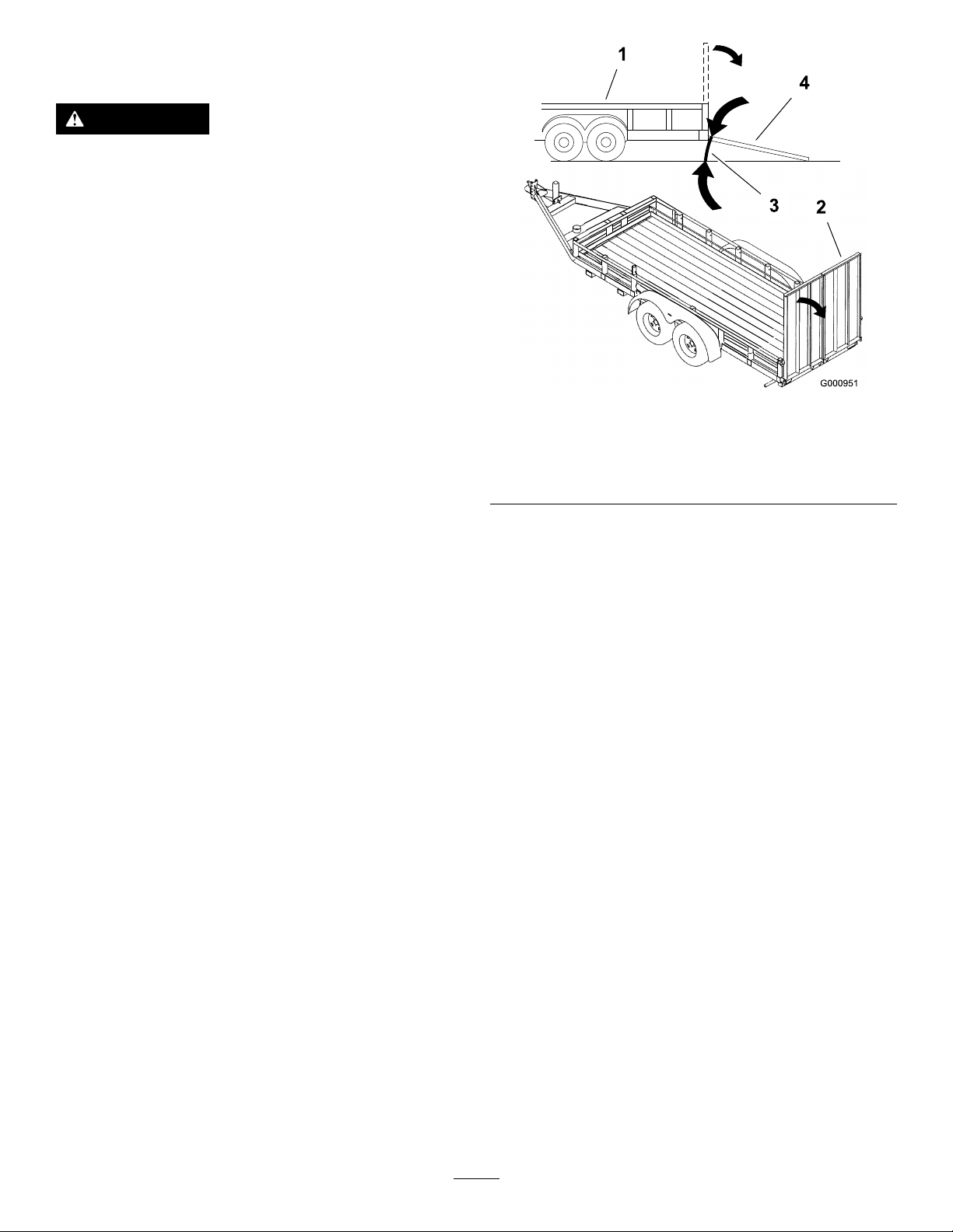
Figure28
1.Trailer3.Notgreaterthan
2.Full-widthramp
15degrees
4.Full-widthramp(sideview)
•Y oushoulddetermineifitisbesttohavethe
platformupordownwhenloading,dependingon
conditions.Ifitisnotpossibletouse1full-width
ramp,useenoughindividualrampstosimulatea
full-width,continuousramp.
g000951
Important:Donotattempttoturnthemachine
whileontheramp;youmaylosecontrolanddrive
offtheside.
•Useextremecautionwhenloadingunitsonto
trailersortrucks.
•Use1full-widthrampthatiswideenoughto
extendbeyondthereartiresinsteadofindividual
rampsforeachsideofthemachine(Figure28).
Theplatform,whendownandlockedintoposition,
mustextendbackbetweentherearwheels,and
servesasastopfortippingbackward.Havinga
full-widthrampprovidesasurfacefortheplatform
tocontactifthemachinestartstotipbackward.
Withtheplatformup,afull-widthrampprovidesa
surfacetowalkonbehindthemachine.
•Therampshouldbelongenoughsothatthe
anglesdonotexceed15degrees(Figure28).
Asteeperanglemaycausetinecomponentsto
getcaught,asthemachinemovesfromrampto
trailerortruck.Asteeperanglemayalsocause
themachinetotipbackward.Ifloadingonornear
aslope,positionthetrailerortrucksoitisonthe
downsideoftheslopeandtherampextendsup
theslope.Thisminimizestherampangle.The
trailerortruckshouldbeaslevelaspossible.
•Avoidsuddenaccelerationwhendrivinguparamp
andsuddendecelerationwhenbackingdowna
ramp.Bothmaneuverscancausethemachineto
tipbackward.
27

TransportingtheMachine
Useaheavy-dutytrailerortrucktotransportthe
machine.Ensurethatthetrailerortruckhasall
thenecessarybrakes,lighting,andmarkingas
requiredbylaw.Pleasecarefullyreadallthesafety
instructions.
1.Raisethetinesofthemachinebeforedriving
ontothetrailerortruck.
2.Ifusingatrailer,connectittothetowingvehicle
andconnectthesafetychains.
3.Ifapplicable,connectthetrailerbrakes.
4.Loadthemachineontothetrailerortruck.
5.Shutofftheengine,removethekey,engagethe
parkingbrake,andclosethefuelvalve.
6.Engagetheparkingbrakeandblockthetires.
7.Usethetie-downpointsonthemachineto
securelybindthemachinetothetrailerortruck
withstraps,chains,cable,orropes(Figure29).
Note:Refertoyourlocalordinancesforspecic
trailerandtie-downregulations.
1.Tie-downpoints
g025949
Figure29
28

Maintenance
MaintenanceSafety
Information
WARNING
Whilemaintenanceoradjustmentsarebeing
made,someonecouldstarttheengine.
Accidentalstartingoftheenginecould
seriouslyinjureyouorotherbystanders.
Removethekeyfromtheignitionswitch,
engageparkingbrake,andpullthewire(s)
offthesparkplug(s)beforeyoudoany
maintenance.Alsopushthewire(s)asideso
itdoesnotaccidentallycontactthespark
plug(s).
•Parkmachineonlevelground,raisethetines,
setparkingbrake,stopengine,removekeyor
disconnectsparkplugwire.Waitforallmovement
tostopandallowthemachinetocoolbefore
adjusting,cleaningorrepairing.Neverallow
untrainedpersonneltoservicemachine.
WARNING
Theenginecanbecomeveryhot.Touching
ahotenginecancausesevereburns.
Allowtheenginetocoolcompletelybefore
serviceormakingrepairsaroundthe
enginearea.
•Disconnectbatteryorremovesparkplugwire
beforemakinganyrepairs.Disconnectthe
negativeterminalrstandthepositivelast.
Reconnectpositiverstandnegativelast.
•Keepthemachine,guards,shieldsandall
safetydevicesinplaceandinsafeworking
condition.Frequentlycheckforwornor
deterioratingcomponentsandreplacethemwith
themanufacturer’srecommendedpartswhen
necessary.
WARNING
Removalormodicationoforiginal
equipment,partsand/oraccessories
mayalterthewarranty ,controllability,
andsafetyofthemachine.Unauthorized
modicationstotheoriginalequipmentor
failuretouseoriginalToropartscouldlead
toseriousinjuryordeath.Unauthorized
changestothemachine,engine,fuelor
ventingsystem,mayviolateapplicable
safetystandardssuchas:ANSI,OSHAand
NFPAand/orgovernmentregulationssuch
asEP AandCARB.
•Usecarewhencheckingandservicingtines.Wrap
thetine(s)orweargloves,andusecautionwhen
servicingthem.Onlyreplacedamagedtines.
Neverstraightenorweldthem.
•Usejackstandstosupportthemachineand/or
componentswhenrequired.
CAUTION
Raisingthemachineforserviceor
maintenancerelyingsolelyonmechanical
orhydraulicjackscouldbedangerous.
Themechanicalorhydraulicjacksmaynot
beenoughsupportormaymalfunction
allowingthemachinetofall,whichcould
causeinjury.
Donotrelysolelyonmechanicalor
hydraulicjacksforsupport.Useadequate
jackstandsorequivalentsupport.
•Carefullyreleasepressurefromcomponentswith
storedenergy.
29

WARNING
Hydraulicuidescapingunderpressure
canpenetrateskinandcauseinjury.Fluid
accidentallyinjectedintotheskinmustbe
surgicallyremovedwithinafewhoursby
adoctorfamiliarwiththisformofinjuryor
gangrenemayresult.
–Ifequipped,makesureallhydraulic
uidhosesandlinesareingood
conditionandallhydraulicconnections
andttingsaretightbeforeapplying
pressuretohydraulicsystem.
–Keepbodyandhandsawayfrom
pinholeleaksornozzlesthatejecthigh
pressurehydraulicuid.
–Usecardboardorpaper,notyourhands,
tondhydraulicleaks.
–Beforeperforminganyworkonthe
hydraulicsystem:
–Safelyrelieveallpressureinthe
grounddrivehydraulicsystemby
placingthemotioncontrolleversin
neutralandshuttingofftheengine.
–Safelyrelieveallpressureinthe
auxiliaryhydraulicsystembyshutting
offtheengine,turningtheignition
switchtothe“ON”position,and
pressingthetinegroundengagement
switch.Oncethetineshavelowered
totheground,releasethetineground
engagementswitchandturntheignition
switchtothe“OFF”position.
•Keephandsandfeetawayfrommovingparts.
Ifpossible,DoNotmakeadjustmentswiththe
enginerunning.Ifthemaintenanceoradjustment
procedurerequiretheenginetoberunningand
componentsmoving,useextremecaution.
WARNING
Contactwithmovingpartsorhotsurfaces
maycausepersonalinjury .
Keepyourngers,hands,andclothing
clearofrotatingcomponentsandhot
surfaces.
•Checkallboltsfrequentlytomaintainproper
tightness.
30

RecommendedMaintenanceSchedule(s)
MaintenanceService
Interval
Aftertherst5hours
Aftertherst100hours
Beforeeachuseordaily
Every25hours
Every50hours
MaintenanceProcedure
•Changetheengineoil.
•Changetheengine-oillter(moreofteninextremelydustyorsandyconditions).
•Checkthetorqueofthewheelhubnuts.
•Checkthetorqueofthetransmissionoutputshaftnut.
•Changetheauxiliaryhydraulicreservoirlteranduid.
•Changethetransmissionlters.
•Fillthetransmissionwithuidwhenchangingthelter.
•Lubricatethechains.
•Checktheengine-oillevel.
•Checkthesafety-interlocksystem.
•Checktheconditionofthesprockets.
•Checktheconditionandtensionofthechains.
•Checkthetines.
•Checkforloosehardware.
•Cleantheengineandtheexhaustsystemarea(moreoftenindryordirtyconditions).
•Cleanthegrassanddebrisbuildupfromthemachine.
•Greasethejackshaftbearings.
•Greasethewheelbearings.
•Greasethetineshaftbearings.
•Greasethetineassemblyidlers.
•Greasethecontrolpivots.
•Checksparkarrester(ifequipped).
•Checkthepressureinthetires.
•Checktheconditionandtensionofthebelts.
•Checktheauxiliaryhydraulic-uidlevel.
•Checkthehydraulictransmissionuidlevel.
Every80hours
Every100hours
Every160hours
Every250hours
Every500hours
Every800hours
•Removetheengineshroudsandcleanthecoolingns.
•Changetheengineoil.
•Changetheengine-oillter(moreofteninextremelydustyorsandyconditions).
•Check,cleanandgapthesparkplug.
•Servicethefoamair-cleanerelement(moreofteninextremelydustyorsandy
conditions).
•Changetheauxiliaryhydraulicreservoirlteranduid.
•Changethetransmissionlters.
•Fillthetransmissionwithuidwhenchangingthelter.
•Replacethepaperair-cleanerelement(moreofteninextremelydustyorsandy
conditions).
•Replacethefuellter.
Monthly
Yearly
•Checkthebattery.
•Greasethefrontcasterpivots.
•Greasethebeltidlerpivot.
•Greasethecasterpivotsandhubs.
•Lubricatethecaster-wheelhubs.
•Lubricatethecaster-wheelhubs.
•Checkthetorqueofthewheelhubnuts.
•Checkthetorqueonthewheellugnuts.
•Checkthetorqueofthetransmissionoutputshaftnut.
•Preparethemachineforstorage.
31
Pre-Maintenance
AccessingtheConsole
Procedures
PreparingfortheMachine
forMaintenance
Performthefollowingbeforeservicing,cleaning,or
makinganyadjustmentstothemachine.
1.Parkthemachineonalevelsurface.
2.Shutofftheengine,engagetheparkingbrake,
waitforallmovingpartstostop.
3.Removethekeyfromthekeyswitch.
Compartment
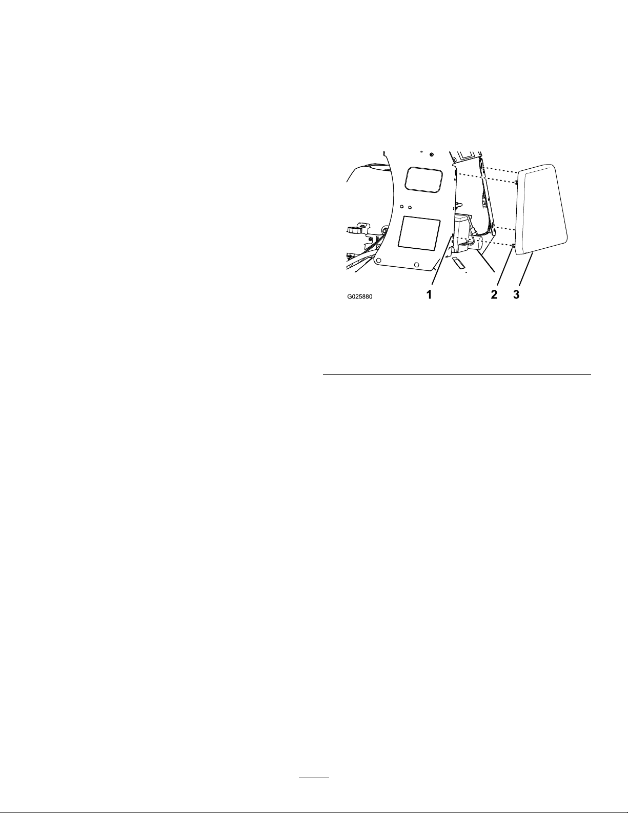
RemovingtheConsolePad
1.Loosenthe4anged-headboltsthatsecurethe
padtotheleftandrightconsolepanels(Figure
30).
Figure30
1.Keyholeslot(console
panel)
2.Fanged-headbolt
3.Pad
g025880
2.Lifttheconsolepad(Figure30)approximately
13mm(1/2inch).
3.Pulltheconsolepadstraightbackandremove
thepadfromthemachine(Figure30).
InstallingtheConsolePad
1.Alignthe4anged-headboltsattheforward
faceoftheconsolepadtothe4keyholeslotsin
theframeoftheconsole(Figure30).
2.Movethepadforwarduntilthepadisushto
theconsoleframe(Figure30).
3.Movethepaddownuntiltheanged-headbolts
areseatedinthekeyholeslots(Figure30).
4.Tightentheanged-headboltsto1978to2542
N∙cm(175to225in-lb).
32

Lubrication
LubricatingtheGrease
Fittings
Greasetype:NationalLubricatingGreaseInstitute
(NGLI)grade#2multi-purposegungrease.
Note:Refertothelubricationchartforservice
intervals.
LubricationChart
Fitting
Locations
Frontcaster
pivots
Jackshaft
bearings
Wheelbearings1225hours
Tineshaft
bearings
Tineassembly
idlers
Controlpivots
Beltidlerpivot11Yearly
Frontcaster
hubs
Initial
Pumps
*0
1825hours
1425hours
1225hours
1450hours
*0
Numberof
Places
2Yearly
2Yearly
2.Wipecleanthegreasettingswitharag(Figure
31).
3.Connectagreaseguntothetting(Figure31).
4.Pumpgreaseintothettingsuntilgreasebegins
tooozeoutofthebearings.
5.Wipeupanyexcessgrease.
LubricatingtheChains
ServiceInterval:Beforeeachuseordaily
Lubricanttype:Oilorchainlubricant.
Service
Interval
Important:Donotlubricatechainswith
penetratingoilorsolvents.
1.Shutofftheengine,engagetheparkingbrake,
waitforallmovingpartstostop,andremove
thekey.
2.Raisethemachineandsupportitwithjack
standswitha460kg(1,015lb)capacity.
CAUTION
Raisingthemachineforservice
ormaintenancerelyingsolelyon
mechanicalorhydraulicjackscouldbe
dangerous.Themechanicalorhydraulic
jacksmaynotbeenoughsupportormay
malfunctionallowingthemachinetofall,
whichcouldcauseinjury .
Figure31
1.Frontcasterpivots5.Tineassemblyidlers
2.Jackshaftbearings6.Controlpivots
3.Wheelbearings7.Beltidlerpivot
4.Tineshaftbearings
8.Frontcasterhubs
1.Shutofftheengine,engagetheparkingbrake,
waitforallmovingpartstostop,andremove
thekey.
Donotrelysolelyonmechanical
orhydraulicjacksforsupport.Use
adequatejackstandsorequivalent
support.
3.Starttheengineandmovethethrottlelevel
aheadtothehalf-throttleposition.
WARNING
Youmustruntheengineandturnthe
drivewheelssothatyoucanperform
adjustments.Contactwithmovingparts
orhotsurfacesmaycausepersonal
injury.
g020222
Keepyourngers,hands,andclothing
clearofrotatingcomponentsandhot
surfaces.
4.Disengagetheparkingbrake.
5.Withtheenginerunning,slowlymovethe
motion-controlleversforwardandlubricateall6
chains(Figure69).
6.Checktheconditionandtensionofthechains;
refertoCheckingtheConditionandTensionof
theChains(page56).
33

LubricatingtheCasters
Greasetype:NationalLubricatingGreaseInstitute
(NGLI)gradeNo.2multi-purposegungrease.
LubricatingtheCaster-Hubs
Bearings
ServiceInterval:Yearly
GreasingtheCasterPivots
ServiceInterval:Yearly
1.Removecapandhexplugfromthetopofthe
casterpivot(Figure32).
Figure32
RemovingtheCaster-WheelAssembly
1.Shutofftheengine,engagetheparkingbrake,
waitforallmovingpartstostop,andremove
thekey.
2.Liftthefrontofthemachineandsupportitwith
jackstands.
3.Removethewheelnutandbolt,andremovethe
caster-wheelassemblyfromthefork(Figure33).
g025953
Figure33
1.Wheelbolt3.Wheelnut
g025955
2.Caster-wheelassembly
1.Hexplug
2.Greasetting4.Cap
2.Threadgreasettinginhole(Figure32).
3.Pumpgreaseintothettinguntilgreaseoozes
outaroundtopbearing(Figure32).
4.Removegreasettingandinstalltheplugthat
youremovedin1(Figure32).
5.Installthecapthatyouremovedinstep1(Figure
32).
6.Repeatsteps1through5totheothercaster.
3.Casterpivot
DisassemblingtheCaster-WheelHuband
GreasingtheBearings
ServiceInterval:Yearly
Important:Usenewbearingsealswhen
lubricatingthecaster-wheelhubs.
Important:Topreventsealandbearingdamage,
checkthebearingadjustmentoften.Spinthe
castertire.Thetireshouldnotspinfreely(more
than1or2revolutions)orhaveanysideplay.If
thewheelspinsfreely,adjusttorqueonspacer
nutuntilthereisaslightamountofdrag.Apply
thread-lockingcompound.
Greasetype:NationalLubricatingGreaseInstitute
(NGLI)gradeNo.2multi-purposegungrease.
1.Removethe2sealguardsfromthewheelhub
(Figure34).
34

Figure34
1.Axle(spacernutstill
assembled)
2.Hub5.Bearingseal
3.Bearing
4.Spacernut
6.Sealguard
2.Remove1ofthespacernutsfromtheaxle
assemblyinthecasterwheel(Figure34).
Note:Notethatthread-lockingcompoundhas
beenappliedtolockthespacernutstotheaxle
(Figure34).
3.Removetheaxle(withtheotherspacernutstill
assembledtoit)fromthecaster-wheelassembly
(Figure34).
4.Pryoutbothbearingseals(Figure34).
Note:Discardtheoldseals.
5.Removebothbearingsandinspectthemfor
wearordamage(Figure34).
Note:Replacethebearingifitiswornor
damaged.
6.Packthe2bearingswiththespeciedgrease.
AssemblingtheCaster-WheelHub
1.Install1bearingintothehubofthewheel(Figure
34).
2.Installthebearingsealintothehubatthe
bearing(Figure34).
3.Ifyouremoved(orbrokeloose)bothofthe
spacernutsfromtheaxleassembly,perform
thefollowing:
A.Cleanthethreadsoftheaxleandspacer
nut.
B.Applyathread-lockingcompoundtothe
threadsat1endoftheaxle.
C.Threadtheaxlenut,withthewrenchats
facingoutward,ontotheendoftheaxlethat
ispreparedwiththread-lockingcompound
(Figure34).
mm(1/8inch)fromtheoutersurfaceofthe
spacernuttotheendoftheaxleinsidethe
nut.
4.Inserttheassemblednutandaxleintothewheel
atthesideofthewheelwiththenewsealand
bearing(Figure34).
5.Withtheopenendofthewheelfacingup,llthe
areainsidewheelcavity(aroundtheaxle)with
thespeciedgrease.
g025954
6.Installtheotherbearingandnewsealintothe
wheel(Figure34).
7.Applyathread-lockingcompoundtothesecond
spacernutandthreaditontotheaxlewiththe
wrenchatsfacingoutward.
8.T orquethespacernutto8to9N∙m(75to80
in-lb),loosen,thentorqueit2to3N∙m(20to
25in-lb).
Important:Ensurethattheaxledoesnot
extendbeyondeithernut.
9.Installthesealguardsoverthewheelhub
(Figure34).
InstallingtheCaster-WheelAssembly
1.Aligntheholeintheaxleofthecaster-wheel
assemblybetweentheholesintheforkofthe
caster(Figure33).
2.Securethewheelassemblytotheforkwiththe
wheelnutandbolt(Figure33)thatyouremoved
instep3ofRemovingtheCaster-Wheel
Assembly(page34).
3.T orquethewheelnutto91to1 13N∙m(67to
83ft-lb).
Note:Donotthreadspacernutallthe
wayontotheaxle.Leaveapproximately3
35

EngineMaintenance
2.Inspectthebothelementsfortears,anoilylm,
ordamaged(Figure35).
ServicingtheAirCleaner
Inspectthefoamandpaperelements,andreplace
themiftheyaredamagedorexcessivelydirty .
Important:Donotapplyoiltothefoamorpaper
element.
AccessingtheFoamandPaper
Elements
1.Shutofftheengine,engagetheparkingbrake,
removethekey,andwaitforallmovingpartsto
stopbeforeleavingtheoperatingposition.
2.Cleanaroundtheaircleanertopreventdirtfrom
gettingintotheengineandcausingdamage
(Figure35).
Important:Replacetheelement(s)ifitis
wornordamaged.
3.Washthefoamelementinliquidsoapand
warmwater.Whentheelementisclean,rinse
itthoroughly.
4.Drytheelementbysqueezingitinacleancloth.
5.Assemblethefoamelementontothepaper
element(Figure35).
6.Installtheair-cleanerelementsontotheinlet
ductoftheengine(Figure35).
7.Rotatethethumbscrewofthehoseclamp
clockwise(Figure35).
8.Assembletheair-cleanercoverontotheengine
androtatethecoverknobs1/4turnclockwise.
ReplacingthePaperAir-Cleaner
Element
ServiceInterval:Every500hours—Replacethe
paperair-cleanerelement(more
ofteninextremelydustyorsandy
conditions).
Figure35
1.Cover
2.Hoseclamp4.Foamelement
3.Rotatethecoverknobs1/4turncounterclockwise
andremovetheair-cleanercover(Figure35).
4.Rotatethethumbscrewofthehoseclamp
counterclockwiseuntilyoucanseparatethe
air-cleanerassemblyfromtheinletduct(Figure
35).
3.Paperelement
ServicingtheFoamAir-Cleaner
Element
Important:Donotwashthepaperair-cleaner
element.
1.Discardtheoldpaperelement.
2.Assemblethefoamelementontothenewpaper
element(Figure35).
3.Installtheair-cleanerelementsontotheinlet
g012352
ductoftheengine(Figure35).
4.Rotatethethumbscrewofthehoseclamp
clockwise(Figure35).
5.Assembletheair-cleanercoverontotheengine
androtatethecoverknobs1/4turnclockwise.
ServiceInterval:Every250hours(moreoften
inextremelydustyorsandy
conditions).
1.Carefullyremovethefoamelementfromthe
paperelement(Figure35).
36

ServicingtheEngineOil
Engine-OilSpecications
OilType:Detergentoil(APIserviceSJorlater)
Engine-OilCapacity:1.7L(1.8USqt)withthelter
removed;1.5L(1.6USqt)withoutthelterremoved
Engine-OilViscosity:Refertothetablebelow.
Figure36
CheckingtheEngine-OilLevel
g025899
g004216
ServiceInterval:Beforeeachuseordaily
Important:Donotoperatetheenginewiththeoil
levelbelowtheLow(orAdd)markonthedipstick,
orovertheFullmark.
1.Parkthemachineonalevelsurface,engagethe
parkingbrake,shutofftheengine,removethe
key,andwaitforallmovingpartstostopbefore
leavingtheoperatingposition.
2.Allowtheenginetocool.
3.Checktheengine-oillevelasshowninFigure
37.
g025898
Figure37
4.Iftheoillevelislow,wipeofftheareaaround
theoilllcap,removecapandaddthespecied
oiluntiltheoillevelisattheFullmarkonthe
dipstick.
Note:Donotoverlltheenginewithoil.
37

ChangingtheEngineOil
ServiceInterval:Aftertherst5hours
Every100hours
Note:Disposeoftheusedoilatarecyclingcenter.
1.Parkthemachinesothatthedrainsideisslightly
lowerthantheoppositesidetoassuretheoil
drainscompletely.
2.Shutofftheengine,engagetheparkingbrake,
removethekey,andwaitforallmovingpartsto
stopbeforeleavingtheoperatingposition.
3.ChangetheengineoilasshowninFigure39.
Note:Torquedrainplugto27to33N∙m(20
to24ft-lb).
Figure38
4.Slowlypourapproximately80%ofthespecied
oilintothellertube,andslowlyaddthe
additionaloiltobringittotheFullmark(Figure
40).
g025980
Figure40
5.Starttheengineanddrivetoaatarea.
6.Checktheengine-oillevel.
7.Resettheengine-oilservicereminder;referto
ResettingtheEngine-OilMaintenanceReminder
(page38).
ResettingtheEngine-Oil
MaintenanceReminder
1.Preparethemachineformaintenance;refer
toPreparingfortheMachineforMaintenance
(page32).
Note:Youmustengagetheparkingbraketo
resetthemaintenancereminder.
2.CyclethekeyswitchbetweentheRUNposition
andtheOFFposition4timeswithin8seconds.
TheServiceEnginescreendisplaysandashes
(Figure41).
g026005
Figure39
g025979
38
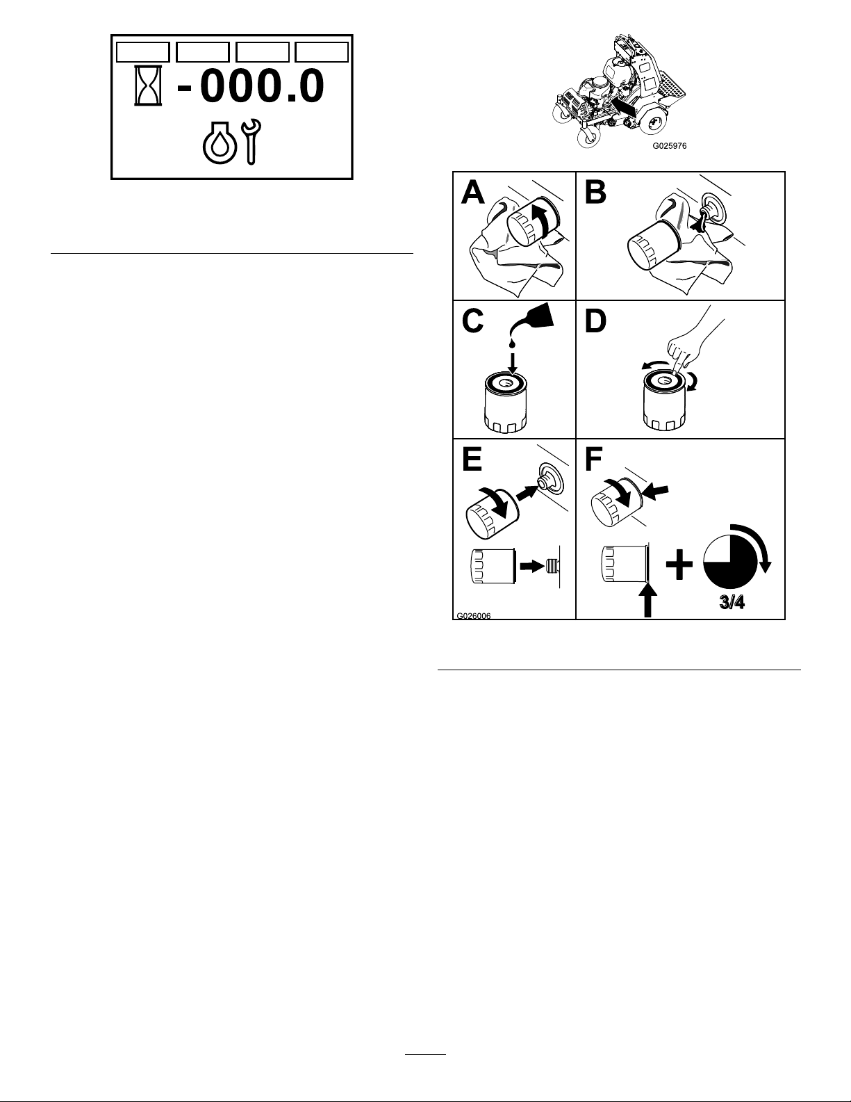
Figure41
ServiceEngineScreen
3.Pressdownthemulti-functionswitch.
Theengine-oilmaintenancereminderresetsto
100.0(hours),exitstheServiceEnginescreen,
andreturnstothedefaultscreen.
Note:YoucanexittheServiceEnginescreenat
anytimebyturningthekeytoeithertheOFForthe
STARTpositions.
ChangingtheEngine-OilFilter
ServiceInterval:Aftertherst5hours(more
ofteninextremelydustyorsandy
conditions).
Every100hours(moreofteninextremelydusty
orsandyconditions).
g025976
g212117
1.Draintheoilfromtheengine;refertoChanging
theEngineOil(page38).
2.Placearagundertheoilltertosoakupany
spilledoil.
Important:Spilledoilmaydrainunderthe
engine.Wipeupanyspilledoil.
3.Changetheengine-oillter(Figure42).
g026006
Figure42
Note:Ensurethattheoil-ltergaskettouches
theengine,andthenturnthelteranextra3/4
turn.
4.Fillthecrankcasewiththespeciedtypeofnew
oil;refertoFigure36.
39

ServicingtheSparkPlug
CheckingtheSparkPlug
ServiceInterval:Every160hours
TypeforallEngines:NGKBPR4ESorequivalent
AirGap:0.75mm(0.03inch)
Makesurethattheairgapbetweenthecenterand
sideelectrodesiscorrectbeforeinstallingthespark
plug.
Useasparkplugwrenchforremovingandinstalling
thesparkplug(s)andagappingtool/feelergaugeto
checkandadjusttheairgap.Installanewspark
plug(s)ifnecessary.
RemovingtheSparkPlug
1.Shutofftheengine,engagetheparkingbrake,
removethekey,andwaitforallmovingpartsto
stopbeforeleavingtheoperatingposition.
2.RemovethesparkplugasshowninFigure43.
Important:Donotcleanthesparkplug(s).
Alwaysreplacethesparkplug(s)whenithasa
blackcoating,wornelectrodes,anoilylm,or
cracks.
Ifyouseelightbrownorgrayontheinsulator,the
engineisoperatingproperly.Ablackcoatingonthe
insulatorusuallymeansthesparkplugisdirty .
Setthegapto0.75mm(0.03inch).
g027479
Figure44
InstallingtheSparkPlug
Figure43
Tightenthesparkplug(s)to22N∙m(16ft-lb).
g025981
g027478
g027735
Figure45
40
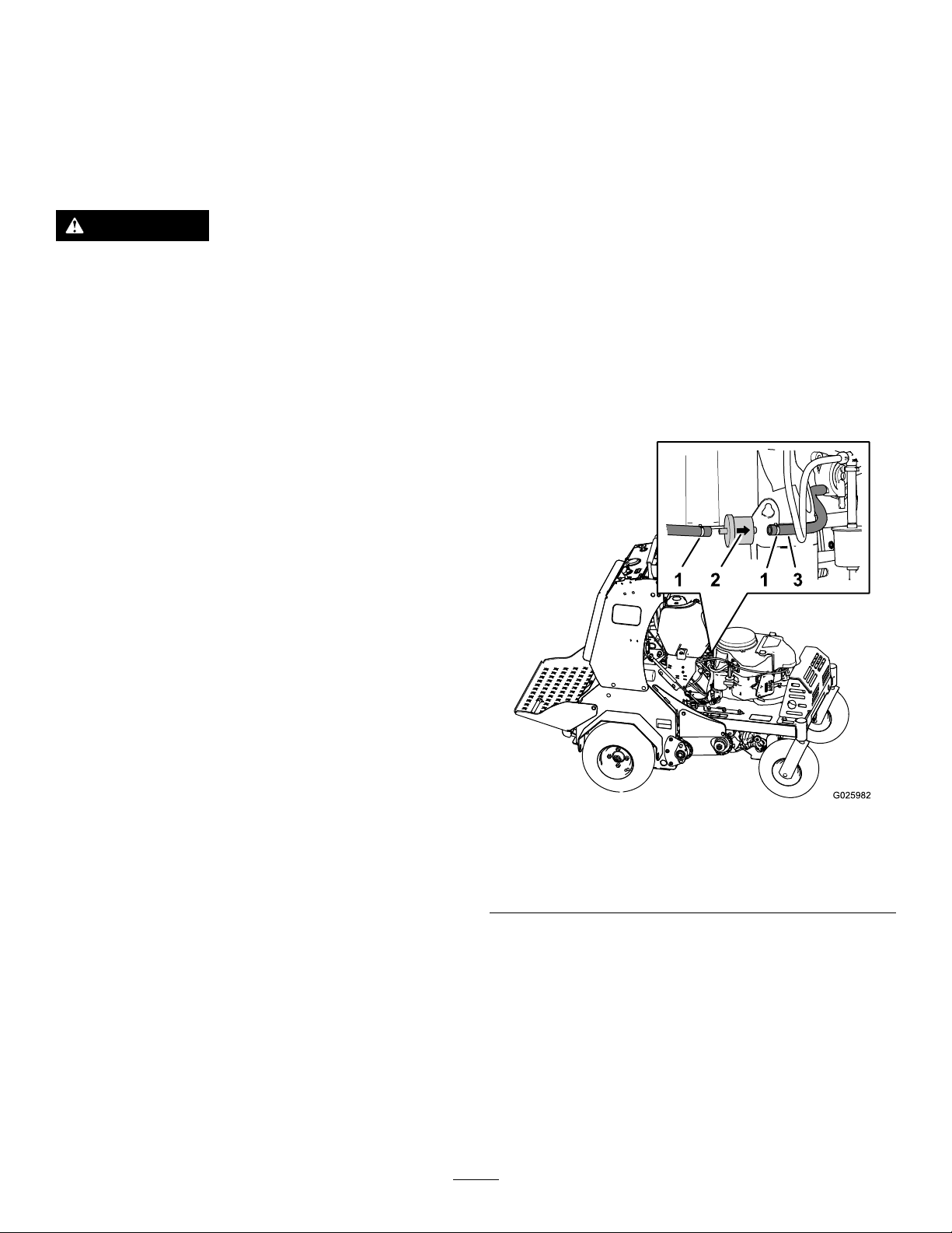
CheckingtheSpark
FuelSystem
Arrester
MachineswithaSparkArrester
Only
ServiceInterval:Every50hours
WARNING
Hotexhaustsystemcomponentsmayignite
fuelvaporsevenaftertheengineisshut
off.Hotparticlesexhaustedduringengine
operationmayigniteammablematerials.
Firemayresultinpersonalinjuryorproperty
damage.
Donotrefuelorrunengineunlessspark
arresterisinstalled.
1.Shutofftheengine,engagetheparkingbrake,
removethekey,andwaitforallmovingpartsto
stopbeforeleavingtheoperatingposition.
2.Allowthemufertocool.
Maintenance
ServicingtheFuelFilter
ReplacingtheFuelFilter
ServiceInterval:Every800hours/Yearly(whichever
comesrst)
Note:Wipeupanyspilledfuel.
1.Shutofftheengine,engagetheparkingbrake,
removethekey,andwaitforallmovingpartsto
stopbeforeleavingtheoperatingposition.
2.Closethefuel-shutoffvalve;refertoUsingthe
Fuel-ShutoffValve(page23).
3.Squeezetheendsofthehoseclampstogether
andslidethemawayfromthelter(Figure46).
3.Checkthesparkarresterforbreaksinthe
screenorwelds.
Note:Replacethesparkarresterifitisworn
ordamaged.
4.Ifyouseethatthescreenisplugged,perform
thefollowing:
A.Removethesparkarrester.
B.Shakeloosetheparticlesfromthearrester
andcleanscreenwithawirebrush.
Note:Soakthearresterscreeninsolvent
ifnecessary.
C.Installsparkarresterontoexhaustoutlet.
g025982
Figure46
1.Hoseclamp3.Hose
2.Flowdirectionarrow(fuel
lter)
4.Removethelterfromthefuelhoses(Figure
46).
Note:Donotinstalladirtylterafteritis
removedfromthefuelline.
5.Installanewlterwiththeow-directionarrow
alignedasillustratedinFigure46.
Note:Ensurethatthefuelhosesarefully
seatedontothehosettingsofthefuellter.
6.Alignthehoseclampsoverthehoseandthe
fuel-lterttings(Figure46).
41

7.Openthefuel-shutoffvalve;refertoUsingthe
Fuel-ShutoffValve(page23).
ElectricalSystem
8.Checkforfuelleaksandrepairifneeded.
9.Wipeupanyspilledfuel.
Maintenance
Checkingthe
Safety-InterlockSystem
ServiceInterval:Beforeeachuseordaily
CAUTION
Ifthesafety-interlockswitchesare
disconnectedordamaged,themachinecould
operateunexpectedly,causingpersonal
injury.
•Donottamperwiththeinterlockswitches.
•Checktheoperationoftheinterlock
switchesdailyandreplaceanydamaged
switchesbeforeoperatingthemachine.
UnderstandingtheSafety-InterlockSystem
Thesafety-interlocksystemisdesignedtopreventthe
enginefromstartingunlessthemotion-controllevers
areintheneutralposition.
CheckingtheSafety-InterlockSystem
1.Disconnectthespark-plugwires.
2.Whileonlevelground,blockthewheelsofthe
machinetopreventunintendedmovement.
3.Disengagetheparkingbrake.
4.Withthemotion-controlleversintheneutral
positionturnthekeytotheSTARTposition—the
startermustnotcrank.
Note:Ifthemachinedoesnotpassthistest,do
notoperatethemachine.ContactyourAuthorized
ServiceDealer.
Important:Itisessentialthattheoperator
safetymechanismsareconnectedandinproper
operatingconditionpriortouse.
42

ServicingtheBattery
RemovingtheBattery
ServiceInterval:Monthly
Alwayskeepthebatterycleanandfullycharged.Use
apapertoweltocleanthebatterycase.Ifthebattery
terminalsarecorroded,cleanthemwithasolutionof
4partswaterand1partbakingsoda.Applyalight
coatingofgreasetothebatteryterminalstoprevent
corrosion.
Voltage:12V
DANGER
Chargingorjumpstartingthebatterymay
produceexplosivegases.Batterygasescan
explodecausingseriousinjury.
•Keepsparks,ames,orcigarettesaway
frombattery.
•Ventilatewhenchargingorusingbatteryin
anenclosedspace.
•Makesureventingpathofbatteryisalways
openoncebatteryislledwithacid.
•Alwaysshieldeyesandfacefrombattery.
WARNING
Batteryterminalsormetaltoolscouldshort
againstmetalmachinecomponents,causing
sparks.Sparkscancausethebatterygasses
toexplode,resultinginpersonalinjury.
•Whenremovingorinstallingthebattery,
donotallowthebatteryterminalstotouch
anymetalpartsofthemachine.
•Donotallowmetaltoolstoshortbetween
thebatteryterminalsandmetalpartsofthe
machine.
WARNING
Incorrectbattery-cableroutingcoulddamage
themachineandcables,causingsparks.
Sparkscancausethebatterygassesto
explode,resultinginpersonalinjury.
•Alwaysdisconnectthenegative(black)
batterycablebeforedisconnectingthe
positive(red)cable.
DANGER
Batteryelectrolytecontainssulfuricacid,
whichisfatalifconsumedandcausessevere
burns.
Donotdrinkelectrolyte,andavoidcontact
withskin,eyes,andclothing.Wearsafety
glassestoshieldyoureyesandrubbergloves
toprotectyourhands.
CAUTION
IfthekeyswitchisintheONposition,there
ispotentialforsparksandengagement
ofcomponents.Sparkscouldcausean
explosionormovingpartscouldaccidentally
engage,causingpersonalinjury.
EnsurethatthekeyswitchisintheOFF
positionbeforechargingthebattery.
•Alwaysconnectthepositive(red)battery
cablebeforeconnectingthenegative
(black)cable.
1.Shutofftheengine,engagetheparkingbrake,
removethekey,andwaitforallmovingpartsto
stopbeforeleavingtheoperatingposition.
2.Removetheconsolepad;refertoRemovingthe
ConsolePad(page32).
3.Onthebattery,lifttheblackterminalcoverfrom
thenegativecable(Figure47).
43

ChargingtheBattery
WARNING
Chargingthebatteryproducesgassesthat
canexplode.
Neversmokenearthebatteryandkeepsparks
andamesawayfromthebattery.
Important:Alwayskeepthebatteryfullycharged
(1.265specicgravity)topreventbatterydamage
whenthetemperatureisbelow0°C(32°F).
1.Removethebatteryfromthechassis;referto
RemovingtheBattery(page43).
Figure47
1.Flangedbolt
2.Terminalcover
(black—negativebattery
terminal)
3.Terminalcover
(red—positivebattery
terminal)
4.Positive(+)battery
terminal
5.Negative(-)battery
terminal
6.Flangednut
7.Batterytray
8.Batterystrap
4.Disconnectthenegativebatterycablefromthe
negative(-)batteryterminal,andremovethe
cablefromthebattery(Figure47).
5.Slidetheredterminalcoveroffthepositive
batteryterminal(Figure47).
6.Disconnectthepositive(red)batterycable,and
removethecablefromthebattery(Figure47).
7.Removethehookofthebatterystrapfromthe
batterytray(Figure47),andremovethebattery.
g025881
2.Checktheelectrolytelevel.
3.Ensurethatthellercapsareinstalledonthe
battery.
4.Chargethebatteryfor1hourat25to30Aor6
hoursat4to6A.
5.Whenthebatteryisfullycharged,unplugthe
chargerfromtheelectricaloutlet,anddisconnect
thechargerleadsfromthebatteryposts(Figure
48).
6.Installthebatteryontothemachineandconnect
thebatterycables;refertoInstallingtheBattery
(page44).
Note:Donotrunthemachinewiththebattery
disconnected;electricaldamagemayoccur.
InstallingtheBattery
1.Placethebatteryontothemachine(Figure47).
2.Securethebatterytothebatterytraywiththe
batterystrap.
3.Installthepositive(red)batterycabletopositive
(+)batteryterminalwithaangedboltand
angednut(Figure47).
4.Slidetheredterminalcoveroverthe
positive-batteryterminal.
5.Installthenegativebatterycableandtheground
wiretothenegative(-)batteryterminalwitha
angedboltandangednut(Figure47).
6.Slidetheblackterminalcoveroverthe
negative-batteryterminal.
Figure48
1.Positivebatterypost
2.Negativebatterypost
3.Red(+)chargerlead
4.Black(-)chargerlead
JumpStartingaDischarged
Battery
ThefollowinginstructionsareadaptedfromtheSAE
J1494Rev.Dec.2001–BatteryBoosterCables
–SurfaceVehicleRecommendedPractice(SAE–
SocietyofAutomotiveEngineers).
44
g000538

DANGER
Jumpstartingaweakbatterythatiscracked,
frozen,haslowelectrolytelevel,oran
open/shortedbatterycell,cancausean
explosionresultinginseriouspersonalinjury.
Donotjumpstartaweakbatteryifthese
conditionsexist.
Choosejumpercableswithcolorcodedor
polaritylabeledcablesorclamps.
ConnectingtheJumperCables
CAUTION
Connectingthejumpercablesincorrectly
(wrongpolarity)canimmediatelydamagethe
electricalsystem.
WARNING
Batteriescontainacidandproduceexplosive
gases.
•Alwaysshieldyoureyesandfacefromthe
battery.
•Donotleanoverthebatteries.
PreparingtoJumpStarttheBattery
CAUTION
Corrosionorlooseconnectionscancause
unwantedelectricalvoltagespikesatanytime
duringthejumpstartingprocedure.
DoNotattempttojumpstartwithlooseor
corrodedbatteryterminalsordamagetothe
enginemayoccur.
1.Checkthecableclampsandbatteryterminals
ofthedischargedbatteryforcorrosion(white,
green,orblue“snow”)andcheckthatthe
hardwarefortheclampsistight.
Cleancorrosionfromthebatteryterminalsand
cableclamps.
2.Checkthatthehardwareforthecableclamps
istight.
Tightenthecable-clamphardwareasneeded.
3.Checkthattheventcapsonthedischarged
batteryandboosterbatteryaretightandlevel.
Becertainofbatteryterminalpolarityand
jumpercablepolaritywhenhookingup
batteries.
1.Connectthepositivejumpercable—red(+)to
thepositive-batteryterminalofthedischarged
batteryasshowninFigure49.
Note:Thepositive-batteryterminaliswiredto
thestarterorsolenoid
Figure49
1.Positive(+)jumpercable
atthedischargedbattery
2.Positive(+)jumpercable
attheboosterbattery
3.Negative(–)jumpercable
attheboosterbattery
4.Negative(–)jumpercable
totheengineblock(the
machinewithadischarged
battery)
5.Boosterbattery
6.Dischargedbattery
7.Engineblock(themachine
withadischargedbattery)
g012785
4.Ifavailable,placedampclothesoverthevent
capsofbothbatteries.
5.Ifyouarejumpstartingfromthebatteryin
anothervehicle,ensurethatithasa12Vlead
acidbattery.
Important:Ensurethatthe2vehiclesdo
nottouch.
6.Ensurethattheboosterbatteryisfullycharged
with12.6voltsorgreater.
7.Selectproperlysizedjumpercables(4to6
AWG)withshortlengthstoreducevoltagedrop
betweensystems.
2.Connecttheotherendofthepositivecable
tothepositive-batteryterminalofthebooster
battery(Figure49).
3.Connectthenegativejumpercable—black(–)
tothenegative-batteryterminalofthebooster
battery.
4.Atthemachinewithadischargedbattery,
connecttheotherendofthenegativejumper
cabletotheengineblock,atalocationaway
fromthebatteryandbelts(Figure49).
45

StartingtheEngineandRemovingtheJumper
Cables
1.Starttheengine.
2.Removethenegativecablefromtheengine
block(Figure49).
3.Removethenegativecablefromthedischarged
battery(Figure49).
DriveSystem
Maintenance
CheckingtheAirPressure
intheTires
4.Removethepositivecablefromthebooster
battery(Figure49)
5.Removethepositivecablefromthedischarged
battery(Figure49)
ServicingtheFuses
Theelectricalsystemisprotectedbyfuses,and
requiresnomaintenance.Ifafuseblows,checkthe
componentorcircuitforamalfunctionorshort.
1.Releasethecushionfromtherearofthe
machine.
2.Removethenegative-batterycablefromthe
batteryterminal.
Note:Ensurethatthenegativebatterycable
doesnottouchthebatteryterminal.
3.Pullthefusefromthesocketofthefuseblock
(Figure50).
ServiceInterval:Every50hours
Note:Thesemi-pneumaticcastertiresdonotneed
tobeinated.
1.Shutofftheengine,engagetheparkingbrake,
removethekey,andwaitforallmovingpartsto
stopbeforeleavingtheoperatingposition.
2.Checkthepressureofthedrivetires.
3.Inatethedrivetiresto83to97kPa(12to14
psi).
CheckingtheWheelHub
Nuts
ServiceInterval:Aftertherst5hours
Yearly
Torquethewheelhubnuts(Figure51)to285to350
N∙m(210to260ft-lb).
Note:Donotuseanti-seizecompoundonthewheel
hub.
Figure50
1.Fuseblock
4.Installafuseofthesametypeandamperesinto
thesocketofthefuseblock(Figure50).
5.Installthenegative-batterycablefromthebattery
terminal;refertosteps5and6ofInstallingthe
Battery(page44).
g026029
Figure51
g025983
1.Lugnut2.Hubnut
46

CheckingtheTorqueofthe
AdjustingtheCasterPivot
WheelLugNuts
ServiceInterval:Yearly
Torquethewheellugnuts(Figure51)to122to129
N∙m(90to95ft-lb).
CheckingtheTorqueofthe
TransmissionOutputShaft
Nut
ServiceInterval:Aftertherst5hours
Yearly
Torquethenut(Figure52)onthetransmissionoutput
taperedshaftto285to353N∙m(210to260ft-lb).
BearingsPre-Load
Note:Ifyoudisassemblethecasterpivotbearings,
ensurethatthespring-discwashersareinstalledas
showninFigure53.
1.Removedustcapfromcasterhub(Figure53).
g026022
Figure53
1.Transmissionoutputshaftnut
Figure52
1.Dustcap
2.Locknut
3.Spring-discwashers
g025989
2.Tightenthelocknutclockwiseuntilthe
spring-discwashersareat(Figure53).
3.Rotatethelocknutcounterclockwise1/4turn
(Figure53).
4.Installthedustcap(Figure53).
4.Spindle
5.Casterhub
47
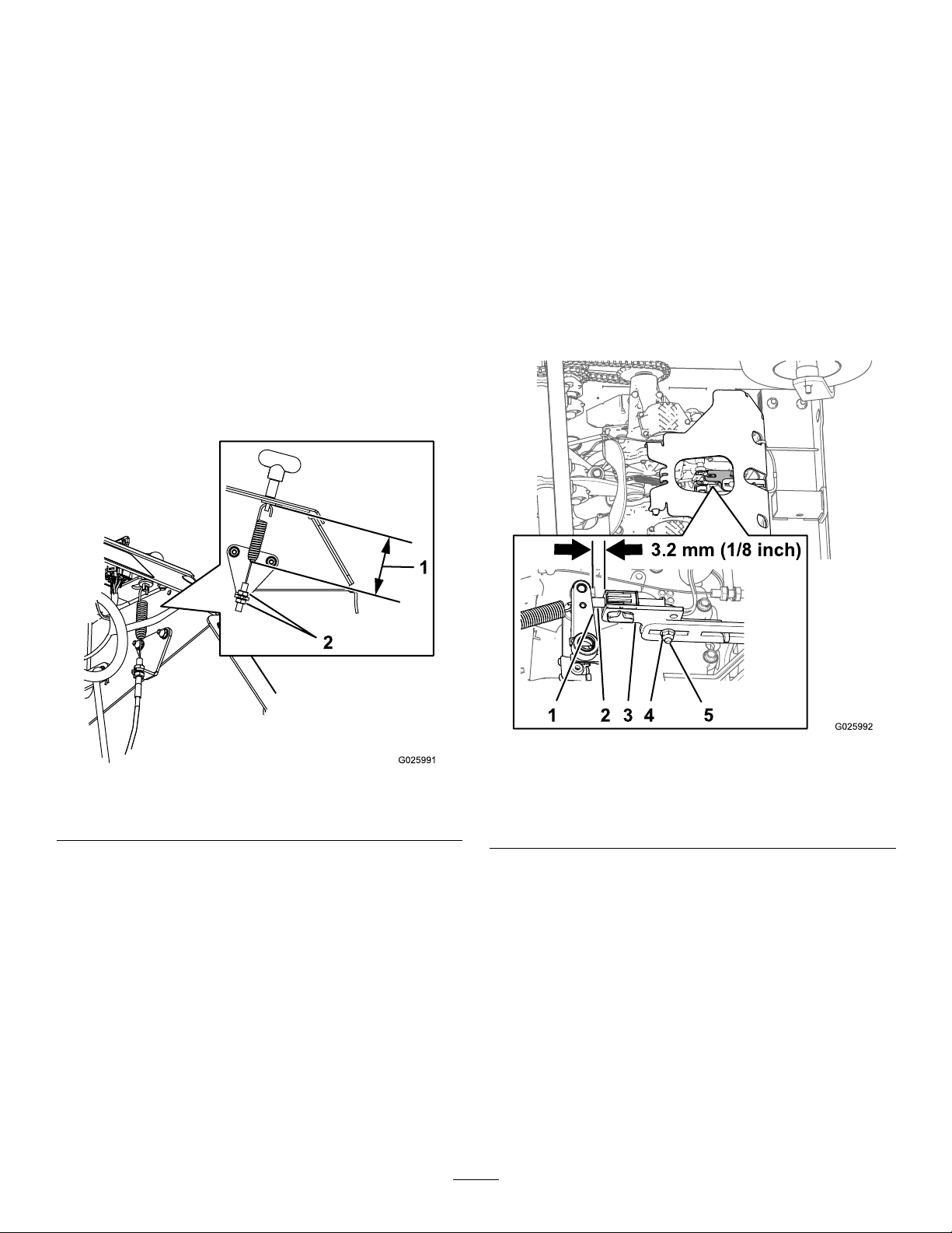
BrakeMaintenance
AdjustingtheBrakeSwitch
1.Parkthemachineonalevelsurface.
AdjustingtheParking
Brake
Iftheparkingbrakedoesnotholdsecurely ,an
adjustmentisrequired.
1.Parkthemachineonalevelsurface.
2.Shutoffengineandwaitforallmovingpartsto
stop.
3.Checktheairpressureinthedrivetires.
Note:Ifneeded,adjusttotherecommended
ination;refertoCheckingtheAirPressurein
theTires(page46).
4.Loosenthejamnutonthebrakecableunder
theconsole(Figure54).
2.Shutofftheengineandwaitforallmovingparts
tostop.
3.Priortheadjustingthebrakeswitchensurethat
theparkingbrakeisproperlyadjusted;referto
AdjustingtheParkingBrake(page48).
4.Engagetheparkingbrake.
5.Checkthedistancebetweentheparking
brake-switchbrackettothebrakearmofthe
transmission(Figure55).
Note:Thedistanceshouldbe3.2mm(1/8
inch).
Figure54
1.7.9cm(3-1/8inch)
5.Engagetheparkingbrake(Figure54).
6.Adjustthejamnutpositionuntil7.9cm(3-1/8
inch)fromthebottomofthelinktothebottomof
thespring(Figure54).
7.Securetheadjustmentofthecablebytightening
thejamnuts(Figure54).
8.Checktheparkingbrake;ifnecessary,repeat
steps4through7.
g025992
g025991
1.Brakearm(transmission)
2.Plunger(brakeswitch)5.Carriagebolt
3.Brake-switchbracket
6.Ifadjustmentisrequired,preformthefollowing:
A.Loosenthelocknutandcarriagebolt
securingtheparkingbrakeswitchbracket
(Figure55).
B.Adjustthepositionofthebrake-switch
bracketuntilthegap(Figure55)between
theswitchbracketandthebrakearmis3.2
mm(1/8inch)
C.Tightenthelocknutandcarriagebolt(Figure
55)securingthebrake-switchbracketto
1017to1243N∙cm(90to110in-lb).
Figure55
4.Locknut
48

BeltMaintenance
CheckingtheCondition
andTensionoftheBelts
ServiceInterval:Every50hours
1.Shutofftheengine,engagetheparkingbrake,
removethekey,andwaitforallmovingpartsto
stopbeforeleavingtheoperatingposition.
2.Raisethemachineandsupportitwithjack
standswitha460kg(1,015lb)capacity.
3.Checktheauxiliarypump-drivebeltcondition
andtension(Figure56).
Note:Thebeltshoulddeect1.3cm(1/2inch)
when1.4kg(3lb)offorceisappliedtothebelt
midwaybetweentheauxiliarypumpandengine
pulleys.Ifthebelttensionistoohighortoolow,
refertoAdjustingtheAuxiliaryPump-DriveBelt
(page49).
4.Checkconditionofthetransmission-drivebelt
(Figure56).
AdjustingtheAuxiliary
Pump-DriveBelt
1.Shutofftheengine,engagetheparkingbrake,
removethekey,andwaitforallmovingpartsto
stopbeforeleavingtheoperatingposition.
2.Loosenthelocknut(3/8inch)thatsecuresthe
auxiliarypump-idlerpulleytothechassisofthe
machine.
Note:Thetransmissionbelthasan
automatic-springtensioner.
Figure56
1.Transmission-drivebelt2.Auxiliarypump-drivebelt
g025997
Figure57
1.Auxiliarypump
2.Auxiliarypump-idlerpulley5.Auxiliarypump-drivebelt
3.Locknut(3/8inch)
3.Adjustthebelttensionasfollows:
4.Adjustmentslot(chassis)
•Movetheauxiliarypump-idlerpulley
rearwardandoutwardtotightenthebelt.
•Movetheauxiliarypump-idlerpulleyforward
g025994
andinwardtoloosenthebelt.
Note:Thebeltshoulddeect1.3cm(1/2inch)
when1.4kg(3lb)offorceisappliedtothebelt
midwaybetweentheauxiliarypumpandengine
pulleys.
4.Tightenlocknutto37to45N∙m(27to33ft-lb).
Replacingthe
Transmission-DriveBelt
Note:Noadjustmentsarerequiredforbelttension.
1.Shutofftheengine,engagetheparkingbrake,
removethekey,andwaitforallmovingpartsto
stopbeforeleavingtheoperatingposition.
2.Insertabreakerbarintothesocketofthe
belt-tensionbracketandmovethebracket
outwardandforward(Figure58).
49

ControlsSystem
Maintenance
Adjustingthe
Traction-ControlLinkage
1.Parkthemachineonalevelsurface.
2.Shutofftheengine,engagetheparkingbrake,
removethekey,andwaitforallmovingpartsto
stopbeforeleavingtheoperatingposition.
3.Pushthecontrolleverallthewayforwardtoward
thefrontreferencebar.
4.Ifthecontrollevercontactsthereference
barorIfthegapbetweenthecontrolleverand
referencebarislargerthan1.6mm(1/16inch),
performthefollowing:
A.Releasethecontrolleverandallowitto
returntotheneutralposition.
B.Removethespring-clevispinfromthefork
ttingofthetraction-controllinkage(Figure
59).
Figure58
1.Transmissionpulley4.Enginepulley
2.Transmission5.T ensionerpulley
3.Socket(belt-tension
bracket)
3.Slipthetransmission-drivebeltoftheengine,
tensioner,andtransmissionpulleys(Figure58).
4.Routethenewtransmission-drivebeltaround
theengine,tensioner,andtransmissionpulleys
asshowninFigure58
5.Releasethebelt-tensionbracketandallowthe
springtotensionthebelt(Figure58).
Note:Makesurethatthebelt-tensionbracket
andpulleycanmovefreely.
g025999
g020223
Figure59
1.Spring-clevispin
2.Locknut
C.Adjusttheforkttingtosettheinitialgap
asfollows:
3.Turnbuckle
•Ifthecontrollevercontactsthe
referencebar,rotatetheforktting
(Figure59)counterclockwise(asviewed
fromthetopofthemachine).
•Ifthegapbetweenthecontrolleverand
referencebarislargerthan1.6mm
(1/16inch),rotatetheforktting(Figure
59)counterclockwise.
D.Installthespringclevispin(Figure59)and
movethecontrolleverforward.
50

E.RepeatstepsAthroughDuntilthereis
agapapproximately1.6mm(1/16inch)
betweenthecontrolleverandthefront
referencebar.
F.Removethespring-clevispin,rotatethe
turnbuckleclockwise1additionalturn,and
insertthespring-clevispin(Figure59).
5.Repeatsteps4Athrough4Ffortheother
traction-controllinkage.
HydraulicSystem
Maintenance
MaintainingtheAuxiliary
HydraulicSystem
HydraulicFluidSpecication
AW-32hydraulicuid
CheckingtheAuxiliary
Hydraulic-FluidLevel
ServiceInterval:Every50hours
1.Parkthemachineonalevelsurface.
2.Lowerthetinestotheground.
3.Shutofftheengine,engagetheparkingbrake,
removethekey,andwaitforallmovingpartsto
stopbeforeleavingtheoperatingposition.
4.Removetheconsolepad;refertoRemovingthe
ConsolePad(page32).
5.Cleantheareaaroundthehydraulicreservoir
cap(Figure60).
Figure60
1.Colduidlevel2.Hotuidlevel
6.Removethecapandcheckhydraulic-uidlevel
inthereservoir(Figure60).
Note:Thehydraulic-uidlevelshouldcoverthe
wordColdthatisembossedintothebafeof
thereservoir.
7.Ifnecessary,addthespeciedhydraulicuidto
thereservoiruntiltheuidcoverstheColduid
levelonthebafe(Figure60).
Note:ThebafeionthereservoirislabeledHot
andCold.Fillthereservoirtotheappropriate
leveldependinguponthetemperatureofthe
uid.Theuidlevelvarieswiththetemperature
51
g314129

oftheuid.TheColdlevelshowsthelevelof
theuidwhenitisat24°C(75°F).TheHot
levelshowsthelevelofuidwhenitisat107°C
(225°F).
Forexample:Iftheuidisatambient-air
temperature,about24°C(75°F),llonlytothe
Coldlevel.Iftheuidisabout65°C(150°F),ll
tohalfwaybetweentheHotandColdlevels.
8.Replacethehydraulicreservoircapandtighten
ituntilitissnug(Figure60).
Note:Donotovertightenthereservoircap.
9.Installtheconsolepad;refertoRemovingthe
ConsolePad(page32).
ChangingtheAuxiliaryHydraulic
ReservoirFluidandFilter
ServiceInterval:Aftertherst100hours
Every250hoursthereafter
1.Shutofftheengine,engagetheparkingbrake,
removethekey,andwaitforallmovingpartsto
stopbeforeleavingtheoperatingposition.
2.Carefullycleanareaaroundthefrontofthe
auxiliarypump,llcapforthereservoir,andlter
(Figure61).
Important:Ensurethatnodirtor
contaminationentershydraulicsystem.
3.Atthefrontoftheauxiliaryhydraulicpump,
removetheinlethosefromthehydraulictting
inthepump,placetheendofthehoseinadrain
container,andallowtheuidtodrain(Figure62).
Figure62
1.Hydraulictting(auxiliary
hydraulicpump)
2.Inlethose
3.Draincontainer
4.Cleanaroundthettingforthehydraulicpump.
5.Rotatetheauxiliaryhydrauliclter
counterclockwiseandremoveitfromthe
baseofthelteradapter(Figure63).Allowthe
uidtodrain.
g026010
Figure61
g026008
g026007
Figure63
1.Auxiliaryhydrauliclter
2.Filteradapter
6.Applyathincoatofspecieduidontotheseal
ofthenewhydrauliclter.
7.Installthelterbyrotatingitclockwiseontothe
lteradapteruntilthesealcontactsthelter
adapter,thentightenthelteranadditional2/3
to3/4turn(Figure63).
8.Installtheinlethoseontothettinginthepump
andtorquethehosettingto50N∙m(37ft-lb).
52

9.Addthespecieduiduntilthelevelreachesthe
Coldlllinelocatedonthereservoirtank;refer
toCheckingtheAuxiliaryHydraulic-FluidLevel
(page51).
10.Starttheengineandraiseandlowerthetines.
11.Lowerthetinestothegroundandrellthe
reservoirtotheColdllline.
4.Ifnecessary,addthespeciedtransmissionuid
untiltheuidlevelisattheFullColdlineofthe
expansiontank(Figure64).
5.Replaceexpansion-tankcapandtightenituntil
snug.
Important:Donotovertightenthe
expansion-tankcap.
Maintainingthe
Transmission
TransmissionFluidSpecication
Toro®HYPR-OIL™500hydraulicuidorMobil®1
15W-50syntheticmotoroil.
Important:Usethespecieduid.Otheruids
couldcausesystemdamage.
CheckingtheTransmissionFluid
Level
ServiceInterval:Every50hours
1.Shutofftheengine,engagetheparkingbrake,
removethekey,andwaitforallmovingpartsto
stopbeforeleavingtheoperatingposition.
2.Allowthemachinetocool.
3.Removethecapfromtheexpansiontankand
checkthehydraulic-uidlevelinthetank(Figure
64).
ChangingtheTransmissionFilters
ServiceInterval:Aftertherst100hours
Every250hoursthereafter
Note:Donotchangethehydraulicsystemuid
(exceptforwhatcanbedrainedwhenchanginglter),
unlesstheuidhasbeencontaminatedorbeen
extremelyhot.
1.Shutofftheengine,engagetheparkingbrake,
removethekey,andwaitforallmovingpartsto
stopbeforeleavingtheoperatingposition.
2.Raisethemachineandsupportitwithjack
standswitha460kg(1,015lb)capacity.
3.Removethe3washer-headbolts(1/4x3/4inch)
thatsecurethelterguardtothetransmission,
andremovetheguard(Figure65).
Note:Thetransmissionuidlevelshouldcover
theFullColdlinemoldedintothesideofthe
tank.
Figure64
1.Cap3.FullColdline
2.Fillerneck(expansion
tank)
g026014
Figure65
1.Transmission
2.Filteradapter5.Filterguard
3.Transmissionlter
4.Cleanthearoundthetransmissionlter(Figure
g025891
65).
5.Alignadrainpanunderthelter.
6.Rotatetheltercounterclockwiseandremove
thelter(Figure65).
4.Washer-headbolts(1/4x
3/4inch)
Note:Allowtheuidtocompletelydrainfrom
thelteradapterofthetransmission.
53

7.Applyathincoatofspecieduidontotheseal
ofthenewtransmissionlter.
8.Installthelterbyrotatingitclockwiseontothe
lteradapteruntilthesealcontactsthebaseof
theadapter,thentightenthelteranadditional
3/4to1turn(Figure65).
9.Installthelterguardwiththe3washer-head
bolts(1/4x3/4inch)thatyouremovedinstep3
(Figure65),andtightentheboltsto1 117to1243
N∙cm(90to110in-lb).
FillingtheTransmissionswith
Fluid
ServiceInterval:Aftertherst100hours
Every250hoursthereafter
1.Raisetherearofmachineupandsupportwith
jackstands(orequivalentsupport)justhigh
enoughtoallowthedrivewheelstoturnfreely.
CAUTION
Raisingthemachineforservice
ormaintenancerelyingsolelyon
mechanicalorhydraulicjackscouldbe
dangerous.Themechanicalorhydraulic
jacksmaynotbeenoughsupportormay
malfunctionallowingthemachinetofall,
whichcouldcauseinjury .
Donotrelysolelyonmechanical
orhydraulicjacksforsupport.Use
adequatejackstandsorequivalent
support.
1.Sightplug
2.Sight-plugport
g026015
Figure66
Lefttransmissionshown
3.Up
g026016
Figure67
Lefttransmissionshown
2.Alignadrainpanunderthesightplugsofthe
transmissions(Figure66andFigure67).
1.Sightplug
2.Sight-plugport
3.Up
3.Attheinboardsideofthetransmission,near
thetop,removethesightplugfrom1ofthe
transmissions(Figure66andFigure67).
4.Addthespecieduidtotheexpansiontank
untiluidowsfromthesight-plugport;referto
CheckingtheTransmissionFluidLevel(page
53).
5.Installthesightplugandtorqueitto244N∙m
(180in-lb).
6.Repeatsteps3through5fortheother
transmission.
7.Addthespecieduidintotheexpansiontank
untiltheuidlevelisattheFullColdlineofthe
tank.
54
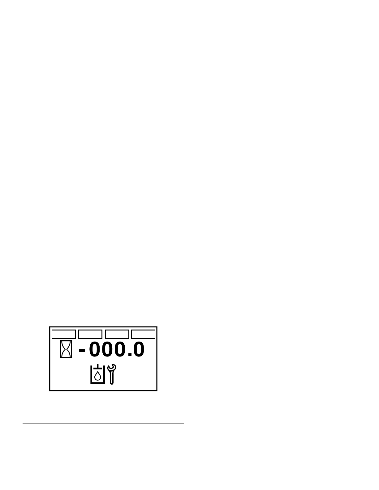
8.Starttheengineandmovethethrottlemidway
betweentheSLOWandFASTpositions
transmissionscreen,andreturnstothedefault
screen.
9.Disengagetheparkingbrake.
10.Slowlymovethemotion-controlleversinthe
forwardandreversedirections5to6times.
Note:Cyclingthetraction-controlsforwardand
reversepurgesairfromthetransmissions.
11.Shutofftheengineandremovethekey.
12.Checktheuidlevelintheexpansiontank,
andaddthespecieduidasrequired;referto
CheckingtheTransmissionFluidLevel(page
53).
13.Repeatsteps8through12untilalltheairis
completelypurgedfromthetransmissions.
Note:Theairispurgedwhenthetransmissions
whenthetransmissionsoperateatnormalnoise
levelsandsmoothlymoveforwardandreverse
atnormalspeeds.
14.Lowerthemachineandremovethejackstands.
15.Resetthetransmission-oilmaintenance
reminder;refertoResettingtheTransmission-Oil
MaintenanceReminder(page55).
Note:Youcanexittheservicetransmissionscreen
atanytimebyturningthekeytoeithertheOFFor
theSTARTpositions.
ResettingtheTransmission-Oil
MaintenanceReminder
1.Preparethemachineformaintenance;refer
toPreparingfortheMachineforMaintenance
(page32).
Note:Youmustengagetheparkingbraketo
resetthemaintenancereminder.
2.CyclethekeyswitchbetweentheRUNposition
andtheOFFposition6timeswithin8seconds.
TheServiceTransmissionscreendisplaysand
ashes(Figure68).
Figure68
ServiceTransmissionScreen
g212118
3.Pressdownthemulti-functionswitch.
Thetransmission-oilmaintenancereminder
resetsto250(hours),exitstheservice
55

ChainMaintenance
•Drivewheelchain
•Tinedrivechain
CheckingtheConditionof
theSprockets
ServiceInterval:Beforeeachuseordaily
1.Shutofftheengine,engagetheparkingbrake,
waitforallmovingpartstostop,andremove
thekey.
2.Inspectsprocketsforwearandreplaceas
required(Figure69).
Thechainsshouldmoveupanddown6to12
mm(1/4to1/2inch).
Figure69
1.Sprockets2.Chains
CheckingtheCondition
andTensionoftheChains
ServiceInterval:Beforeeachuseordaily
1.Shutofftheengine,engagetheparkingbrake,
waitforallmovingpartstostop,andremove
thekey.
2.Checktheconditionandchaintensionforthe
followingchainsatbothsidesofthemachine:
•Jackshaftdrive-chain
g276759
Figure70
1.Tinedrivechain
2.Drivewheelchain
3.Ifthechainspop,snap,orthetensionis
incorrect,adjustthechaintension;referto
AdjustingtheJackshaftDrive-ChainT ension
(page56),AdjustingtheDriveWheelChain
Tension(page57),orAdjustingtheTineDrive
Chain(page58).
g025984
3.Jackshaftdrive-chain
4.6to12mm(1/4-1/2inch)
AdjustingtheJackshaft
Drive-ChainTension
1.Shutofftheengine,engagetheparkingbrake,
removethekey,andwaitforallmovingpartsto
stopbeforeleavingtheoperatingposition.
2.Lifttherearofthemachineandsupportitusing
jackstandsorequivalentsupport.
3.Checkthechainsonbothsidesofthemachine
forpropertension.
Note:Thechainsshouldmoveupanddown6
to12mm(1/4to1/2inch).
4.Ateachsideofthemachine,loosenthe3nuts
andboltsthatsecurethetransmissionmount
56

andtensionerplate,andthe2nutssecuringthe
adjustmentboltatthetensionerplateasshown
inFigure71.
AdjustingtheDriveWheel
ChainTension
Note:Youmustloosenthenutsandboltsthat
securethetransmissionmountandtensioner
plateatbothsidesofthemachine.
1.Shutofftheengine,engagetheparkingbrake,
removethekey,andwaitforallmovingpartsto
stopbeforeleavingtheoperatingposition.
2.Lifttherearofthemachineandsupportitusing
jackstands.
3.Checkthetensionofthedrive-wheelchains
(Figure72).
Note:Thechainsshouldmoveupanddown6
to12mm(1/4to1/2inch).
g025990
Figure72
1.Locknut3.Drive-wheelchain
2.Idlersprocket
Figure71
1.Hydromountingboltsand
nuts
2.Nuts
3.Adjustmentbolt
4.6to12mm(1/4-1/2inch)
5.Guardremovedforclarity
5.Turntheadjustmentbolttomovetransmission
adjustmentplatesandtransmission.
6.Whenthechainscanmoveupanddown6to12
mm(1/4to1/2inch),tightenthenutsonboth
sidesoftheadjustmentbolts.
7.Tightennutsandboltsthatsecurethehydro
mounting.
8.Adjustthetraction-controllinkage,referto
AdjustingtheTraction-ControlLinkage(page
50).
g020261
4.Loosenthelocknutandcarriageboltthatsecure
theidlersprocket(Figure72).
5.Increaseordecreasechaintensionby
performingthefollowing:
•Pushdownandforwardonthesprocket
toincreasethechaintensionasshownin
Figure72.
•Liftupandbackonthesprockettodecrease
thechaintension.
6.T orquethelocknutto91to113N∙m(67to83
ft-lb).
7.Checkthechaintensionandifnecessaryrepeat
steps4through6untilyoucanmovethechain
upanddown6to12mm(1/4to1/2inch).
57
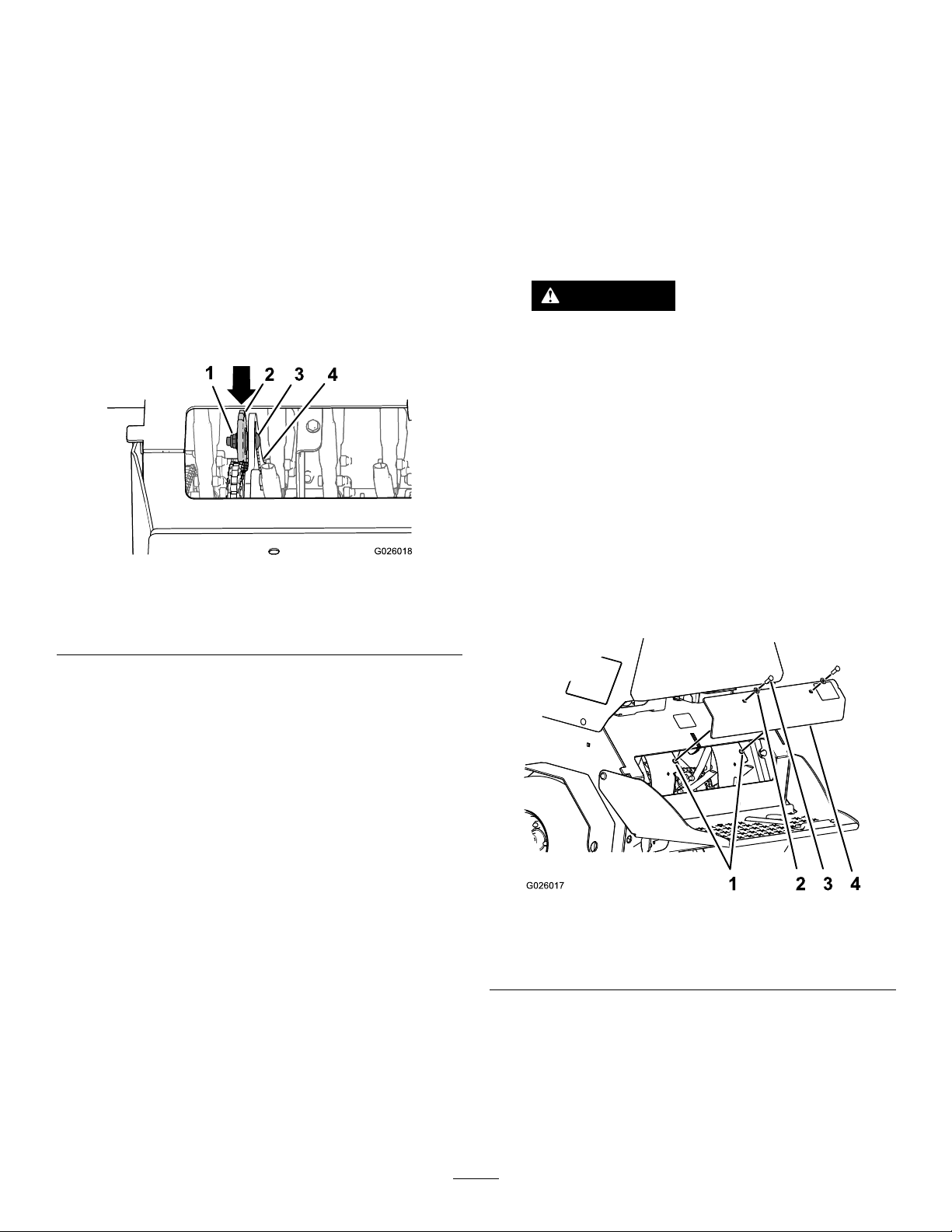
AdjustingtheTineDrive
Chain
1.Shutofftheengine,engagetheparkingbrake,
removethekey,andwaitforallmovingpartsto
stopbeforeleavingtheoperatingposition.
2.Removetherearcover;refertostep3of
CheckingtheTines(page58).
3.Checkthechainsonbothsidesofthemachine
forpropertension.
Note:Thechainsshouldmoveupanddown6
to12mm(1/4to1/2inch).
TineMaintenance
CheckingtheTines
ServiceInterval:Beforeeachuseordaily
1.Shutofftheengine,engagetheparkingbrake,
removethekey,andwaitforallmovingpartsto
stopbeforeleavingtheoperatingposition.
2.Raisethemachineandsupportitwithjack
standswitha460kg(1,015lb)capacity.
CAUTION
4.Loosenthelocknutandcarriageboltthatsecure
theidlersprocket(Figure73).
Figure73
1.Locknut
2.Idlersprocket
5.Increaseordecreasechaintensionby
performingthefollowing:
3.Carriagebolt
4.Slot(trailplate)
•Pushdownandforwardonthesprocket
toincreasethechaintensionasshownin
Figure73.
Raisingthemachineforservice
ormaintenancerelyingsolelyon
mechanicalorhydraulicjackscouldbe
dangerous.Themechanicalorhydraulic
jacksmaynotbeenoughsupportormay
malfunctionallowingthemachinetofall,
whichcouldcauseinjury .
Donotrelysolelyonmechanical
orhydraulicjacksforsupport.Use
adequatejackstandsorequivalent
support.
g026018
3.Removethe2bolts(3/8x1inch)and2washers
(3/8inch)thatsecuretherear-coverpaneltothe
chassis,andremovethepanel(Figure74).
•Liftupandbackonthesprockettodecrease
thechaintension.
6.T orquethelocknutto91to113N∙m(67to83
ft-lb).
7.Checkthechaintensionandifnecessaryrepeat
steps4through6untilyoucanmovethechain
upanddown6to12mm(1/4to1/2inch).
8.Installtherearpanel;refertosteps6and7of
CheckingtheTines(page58).
Figure74
1.Chassisholes3.Bolt(3/8x1inch)
2.Washer(3/8inch)
4.Removerocksandotherdebrisfromthetines.
5.Inspectthetinesforwearanddamage.
4.Rearpanel
Note:Replaceanytinesthatarewornor
damaged.
6.Aligntheholesintherear-coverpaneltothe
holesinthechassis(Figure74).
58
g026017

7.Securethecoverpaneltothechassiswiththe
2boltsand2washers(Figure74)thatyou
removedinstep3,andtorquetheboltsto37to
45N∙m(27to33in-lb)
ChassisMaintenance
CheckingforLoose
Hardware
ServiceInterval:Beforeeachuseordaily
1.Shutofftheengine,engagetheparkingbrake,
removethekey,andwaitforallmovingparts
tostop.
2.Visuallyinspectmachineforanyloosehardware
oranyotherpossibleproblem.
Note:Tightenallloosehardwareorrepairthe
problembeforeoperatingthemachine.
59

Cleaning
RemovingtheEngine
Washthemachineasneededusingwateralone
orwithamilddetergent.Y oumayusearagwhen
washingthemachine.
Important:Donotusebrackishorreclaimed
watertocleanthemachine.
Important:Donotusepower-washingequipment
towashthemachine.Power-washingequipment
maydamagetheelectricalsystem,loosen
importantdecals,orwashawaynecessarygrease
atfrictionpoints.Avoidexcessiveuseofwater
nearthecontrolpanel,engine,andbattery.
Important:Donotwashthemachinewiththe
enginerunning.Washingthemachinewiththe
enginerunningmayresultininternalengine
damage.
CleaningtheEngineand
theExhaustSystemArea
ServiceInterval:Beforeeachuseordaily(more
oftenindryordirtyconditions).
ShroudsandCleaningthe
CoolingFins
ServiceInterval:Every80hours
1.Shutofftheengine,engagetheparkingbrake,
removethekey,andwaitforallmovingpartsto
stopbeforeleavingtheoperatingposition.
2.Removecoolingshroudsfromengine.
3.Cleancoolingnsoftheengine.
Note:Alsocleandust,dirt,andoilfromexternal
enginesurfaces,whichcancauseimproper
cooling.
4.Installthecoolingshroudsintotheengine.
Important:Operatingtheenginewithoutthe
coolingshroudswillcauseenginedamage
fromoverheating.
CleaningtheDebrisfrom
theMachine
CAUTION
Excessivedebrisaroundenginecoolingair
intakeandexhaustsystemareacancause
engine,exhaustarea,andhydraulicsystemto
overheat,whichcancreatearehazard.
Cleanalldebrisfromengineandexhaust
systemarea.
1.Shutofftheengine,engagetheparkingbrake,
removethekey,andwaitforallmovingpartsto
stopbeforeleavingtheoperatingposition.
2.Cleanalldebrisfromscreenatthetopofthe
engine,aroundengineshrouding,andexhaust
systemarea.
3.Wipeupanyexcessivegreaseoroilaroundthe
engineandexhaustsystemarea.
ServiceInterval:Beforeeachuseordaily
Important:Washthemachinewithmilddetergent
andwater.Donotpressurewashthemachine.
Avoidexcessiveuseofwater,especiallynear
thecontrolpanel,aroundtheengine,hydraulic
pumps,andmotors.
1.Shutofftheengine,engagetheparkingbrake,
removethekey,andwaitforallmovingpartsto
stopbeforeleavingtheoperatingposition.
2.Cleanoffanyoil,debris,orgrassbuilduponthe
machineandaeratordeck.
3.Cleanoffanydebrisorgrassunderthechain
guards,aroundthefueltank,andaroundthe
engineandexhaustarea.
60

WasteDisposal
Storage
DisposingoftheEngineOil
Engineoilandhydraulicuidarebothpollutantsto
theenvironment.Disposeofusedoilatacertied
recyclingcenteroraccordingtoyourstateandlocal
regulations.
DisposingoftheBattery
DANGER
Batteryelectrolytecontainssulfuricacid,
whichispoisonousandcancausesevere
burns.Swallowingelectrolytecanbefatalor
cancausesevereburnsifittouchesskin.
•Wearsafetyglassestoshieldeyes,and
rubberglovestoprotectskinandclothing
whenhandlingelectrolyte.
•Donotswallowelectrolyte.
•Intheeventofanaccident,ushwithwater
andcalladoctorimmediately.
Federallawstatesthatbatteriesshouldnotbeplaced
inthegarbage.Managementanddisposalpractices
forbatteriesmustfollowrelevantfederal,state,or
locallaws.
Ifyouarereplacingthebatteryoryourmachineisno
longeroperatedanditisbeingscrapped—removethe
battery;takethebatterytoalocalcertiedrecycling
center.Ifnolocalrecyclingisavailablereturnthe
batterytoanycertiedbatteryreseller.
PreparingtheMachinefor
Storage
ServiceInterval:Yearly
1.Raisethetines,stopthemachine,shutoffthe
engine,engagetheparkingbrake,andremove
thekey.
2.Removedirtandgrimefromtheentiremachine.
Important:Youcanwashthemachine
withmilddetergentandwater.Donot
pressure-washthemachine.Avoid
excessiveuseofwater,especiallynearthe
engineandhydrostaticdrive.
3.Servicetheaircleaner;refertoServicingtheAir
Cleaner(page36).
4.Lubricatethemachine;refertoLubrication
(page33).
5.Changetheengineoil;refertoChangingthe
EngineOil(page38).
6.Checkandtightenallbolts,nuts,andscrews.
Repairorreplaceanypartthatisdamaged.
7.Paintallscratchedorbaremetalsurfaces.Paint
isavailablefromyourAuthorizedServiceDealer.
8.Storethemachineinaclean,drygarageor
storagearea.
9.Coverthemachinetoprotectitandkeepitclean.
61
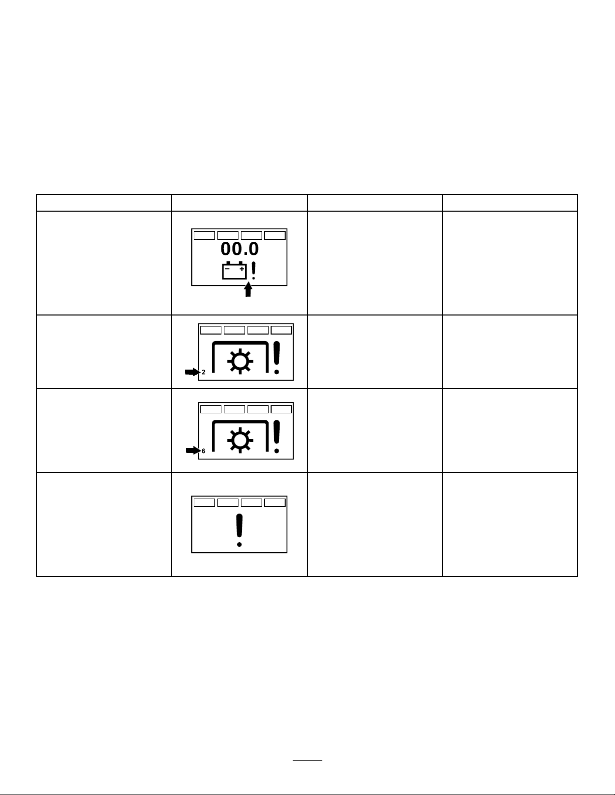
Troubleshooting
Important:Ensurethatalloperator-safetymechanismsareconnectedandinoperatingcondition
beforeusingthemachine.
Thefollowingtablelistscommoncausesoftrouble.Donotattempttoserviceorreplacemajoritemsorany
itemsthatcallforspecialtimingofadjustmentsprocedures(suchasvalves,governor,etc.).Havethiswork
donebyyourEngineServiceDealer.
Note:WhendisconnectingelectricalconnectorsDonotpullonthewirestoseparatetheconnectors.
AlertandErrorMessages
MessageIconDescriptionResolution
VoltageErrorTheignitionkeyisinthe
ValveSolenoidOvercurrent
Error
RUNpositionandthesmart
controller/electronicdepth
controlmeasuresthatthe
electricalsystemislessthan
12.3Vorgreaterthan16V .
Thevoltageerroricondisplays,
andtheLEDstatuslightashes
ared.
Anover-currenteventoccursat
thesolenoidvalve.
Checkthebattery,charging
system,andwiring.
Checkthevalvesolenoidand
inspectitfordamageandwear.
Thevalvesolenoidover-current
errordisplayswiththenumber
2andtheLEDstatuslight
ashesared.
ValveSolenoidOpenError1ofthe2valvesolenoids
ValveSolenoidConnection
Error
orbothvalvesolenoidsare
disconnected.
Thevalvesolenoidopenerror
displayswiththenumber6and
theLEDstatuslightashesa
red.
Thevalvesolenoidsare
connectedwrong(the
connectorforthereliefvalveis
connectedtotheothervalve
solenoid).
Thevalvesolenoidconnection
erroralertdisplays,andthe
tineswillnotoperateuntilthe
faultiscorrected.
Connectthevalvesolenoid(s).
Swapthevalvesolenoid
connectors.
62

TroubleshootingTable
Problem
Thestarterdoesnotcrank.
Theenginedoesnotstart,startshard,or
failstokeeprunning.
PossibleCauseCorrectiveAction
1.Theparkingbrakeisnotengaged.1.Engagetheparkingbrake.
2.Thebrakeswitchisnotadjusted
properly.
3.Thebatterydoesnothaveafull
charge.
4.Theelectricalconnectionsare
corroded,loose,ordamaged.
5.Afuseisblown.5.Replacetheblownfuse.
6.Arelayorswitchisdefective.6.ContactanAuthorizedServiceDealer.
1.Thefueltankisempty.1.Fillthefueltank.
2.Thefuel-shutoffvalveisclosed.2.Openthefuel-shutoffvalve.
3.Thethrottleandchokearenotinthe
correctposition.
4.Thereisdirtinthefuellter.4.Replacethefuellter.
5.Thereisdirt,water,orstalefuelisin
thefuelsystem.
6.Theaircleanerisdirty.
7.Theelectricalconnectionsare
corroded,loose,ordamaged.
8.Arelayorswitchisdefective.8.ContactanAuthorizedServiceDealer.
9.Thesparkplugiswornordamaged.
10.Thespark-plugwireisnotconnected.
2.Adjustthebrakeswitch.
3.Chargethebattery.
4.Checktheelectricalconnectionsfor
goodcontact.Cleantheconnector
terminalsthoroughlywithelectrical
contactcleaner,applydielectric
grease,andreconnect.
3.Besurethatthethrottlelevelismidway
betweentheSLOWandFASTpositions,
andthechokeisintheONpositionfor
acoldengineortheOFFpositionfora
warmengine.
5.ContactanAuthorizedServiceDealer.
6.Cleanorreplacetheair-cleaner
element.
7.Checktheelectricalconnections
forgoodcontact.Cleanconnector
terminalsthoroughlywithelectrical
contactcleaner,applydielectric
grease,andreconnect.
9.Clean,adjust,orreplacethespark
plug.
10.Checkthespark-plugwireconnection.
Theenginelosespower.
Theengineoverheats.
Themachinepullsleftorright(withlevers
fullyforward).
1.Theengineloadisexcessive.1.Reducethegroundspeedoraeration
2.Theaircleanerisdirty.
3.Theoillevelinthecrankcaseislow.3.Addoiltothecrankcase.
4.Thecoolingnsandairpassagesfor
theengineareplugged.
5.Thereisdirtinthefuellter.5.Replacethefuellter.
6.Thereisdirt,water,orstalefuelisin
thefuelsystem.
1.Theengineloadisexcessive.1.Reducethegroundspeedoraeration
2.Theoillevelinthecrankcaseislow.2.Addoiltothecrankcase.
3.Thecoolingnsandairpassagesfor
theengineareplugged.
1.Thetirepressureindrivetiresisnot
correct.
2.Thetrackingneedsadjustment.2.Adjustthetraction-controllinkage.
depth.
2.Cleanorreplacetheair-cleaner
element.
4.Removetheobstructionsfromthe
coolingnsandairpassages.
6.ContactanAuthorizedServiceDealer.
depth.
3.Removetheobstructionsfromthe
coolingnsandairpassages.
1.Adjustthetirepressureinthedrive
tires.
63

Problem
PossibleCauseCorrectiveAction
Themachinedoesnotdrive.
Thereisabnormalvibration.
Thetinesdonotraise.
Thetinesdonotengagetheground.
1.Thetransmissionbeltworn,loose,or
broken.
2.Thetransmissionbeltisoffapulley.2.Changethebelt.
1.Atineisbent.1.Installanewtine.
2.Thetinemountingboltisloose.2.Tightenthetinemountingbolt.
3.Theenginemountingboltsareloose.3.Tightentheenginemountingbolts.
4.Thereisalooseenginepulleyoridler
pulley.
5.Theenginepulleyisdamaged.
6.Abeltisdamaged.6.Installanewbelt.
7.Thechainsarenotproperlytensioned.
1.Thereisanauxiliarypumpbelt
problem.
2.Thetinedownpressuresettingistoo
low.
3.Thereisashortinthewiringharness.
4.Theauxiliaryreservoirislowonuid.4.Adduidtothereservoir.
1.Thetinedownpressuresettingistoo
low.
2.Thewireharnessortheswitchis
damaged.
3.Theauxiliaryreservoirislowonuid.3.Adduidtothereservoir.
4.Thecylinderstopisinplace.4.Removecylinderstop,clevispinand
1.Changethebelt.
4.Tightentheappropriatepulley.
5.ContactanAuthorizedServiceDealer.
7.Checkthejackshaftdrive-chain
tension,thedrivewheelchaintension,
andthetinedrive-chaintension.
1.T ensionorreplacethebelt.
2.Increasethedownpressure.
3.ContactanAuthorizedServiceDealer.
1.Increasethetine-downpressure.
2.ContactyourAuthorizedService
Dealer.
hairpin.
64

BT01
TERMINAL +
TERMINAL -
BATTERY
S
IGNITION SWITCH
SW01
RUN
START
B
OFF
I
A
FUSE BLOCK
DIS01
FUEL-HOUR METER
B+
NC
SEN A IN
SW PWR
KEY S
START SIG
FOOT
NC
NC
NC
PARK BRAKE
TINE DOWN OUT
TINE UP OUT
DOWN IN
SEN B IN
UP IN
GND-S/D
GND
CAN LO
CAN HI
SW03
BRAKE SWITCH
F01 15A
ACC'Y
F02 20A
MAIN
STARTER RELAY
K03
30
85 86
87
ACC SIGNAL
ACC PWR
GND
CAP01
ACC'Y
NC
CAN HI
CAN LO
PWR -SW
PWR - FUSED
GND
CAP02
SERVICE PORT
SP01
SP02
SP03
SP04
SP05
SW02
FOOT SWITCH
S04
DOWN
(ON)-OFF-(ON)
UP
Relief
Valve
Manifold Assembly
L02
QUADRATURE SENSOR
SEN01
FLYWHEEL
ALT
VT START
BK STARTER SOL GND
GN FUEL
BK GND-S/D
ENGINE
B+
ENG
DC
REG
FUEL SOLENOID
GND
IGNITION
MODULES
RD DC REG
NC
OIL PRES
OIL PRESSURE
F03 20A
REG
D01
DIODE
P13
B
P13
A
SP06
GREEN/BROWN
GREEN/GRAY
WHITE/TAN
WHITE/BLACK
YELLOW/BLACK
BLACK
YELLOW/BLACKYELLOW/BLACK
YELLOW/BLACK
YELLOW/BLACK
BLACK
BLACK
BLACK
BLACK
BLACK
BLACK
BLUE
BLUE
RED/WHITE
WHITE/BLUE
WHITE/BLUE
RED
RED
RED
RED
RED
ORANGE/RED
ORANGE/RED
RED/GREEN
ORANGE
ORANGE
BLUE/RED
BLUE/RED
BLUE
BLUE
BLUE/BLACK
BLUE/BLACK
RED/WHITE
RED/WHITE
RED/WHITE
RED/WHITE
RED/WHITE
RED/WHITE
RED/WHITE
RED/WHITE
BLACK
WHITE/BROWN
WHITE/BROWN
BLACK
BLACK
RED/WHITE
RED/WHITE
RED/GREEN
RED/GREEN
RED/GREEN
RED/GREEN
RED/GREEN
VIOLET/RED
VIOLET/RED
BLACK
BLACK
BLACK
VIOLET/BLACK
VIOLET/BLACK
GREEN
GREEN
YELLOW
YELLOW
BLACK
RED/WHITE
RED/GREEN
RED/GREEN
BLACK
YELLOW/WHITE
YELLOW/WHITE
RED/GREEN
RED/GREEN
RED
BLACK
BLACK
BLACK
BLUE/YELLOW
P07
D
P07
C
A
B
1
3
4
5
7
11
P06
8
9
10
12
2
6
P08
121420
512
9
10
18
17
P08
3
4
7
1611131519
6
8
P11
2
P11
1
P01
A
B
C
P09
1
23456
J01
1
J02
1
P10
2
P10
1
P02
1
PWR
2
GND
3
CHANNEL A4CHANNEL B
P12
13468
P12
2
5
7
P03
Sol A-
2
P04
Sol B-
2
P03
Sol A+
1
P04
Sol B+
1
P05
123
456
J05
J04
BLACK
BLACK
BLACK
BLACK
BLACK
Schematics
ElectricalSchematic(Rev .A)
65
g269827
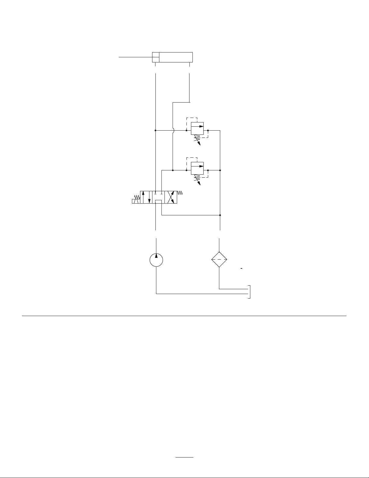
CYLINDER
2.5 inch bore
4 inch stroke
A
B
FILTER
PUMP
.129 in /rev
3
P
T
25 um Nominal
3600 RPM
VALVE
ADJUSTABLE
VALVE
1000 psi
HydraulicSchematic(Rev .A)
g270316
66

CaliforniaProposition65WarningInformation
Whatisthiswarning?
Youmayseeaproductforsalethathasawarninglabellikethefollowing:
WARNING:CancerandReproductiveHarm—www.p65Warnings.ca.gov.
WhatisProp65?
Prop65appliestoanycompanyoperatinginCalifornia,sellingproductsinCalifornia,ormanufacturingproductsthatmaybesoldinorbroughtinto
California.ItmandatesthattheGovernorofCaliforniamaintainandpublishalistofchemicalsknowntocausecancer,birthdefects,and/orother
reproductiveharm.Thelist,whichisupdatedannually,includeshundredsofchemicalsfoundinmanyeverydayitems.ThepurposeofProp65isto
informthepublicaboutexposuretothesechemicals.
Prop65doesnotbanthesaleofproductscontainingthesechemicalsbutinsteadrequireswarningsonanyproduct,productpackaging,orliteraturewith
theproduct.Moreover,aProp65warningdoesnotmeanthataproductisinviolationofanyproductsafetystandardsorrequirements.Infact,the
CaliforniagovernmenthasclariedthataProp65warning“isnotthesameasaregulatorydecisionthataproductis‘safe’or‘unsafe.’”Manyofthese
chemicalshavebeenusedineverydayproductsforyearswithoutdocumentedharm.Formoreinformation,gotohttps://oag.ca.gov/prop65/faqs-view-all
AProp65warningmeansthatacompanyhaseither(1)evaluatedtheexposureandhasconcludedthatitexceedsthe“nosignicantrisklevel”;or(2)
haschosentoprovideawarningbasedonitsunderstandingaboutthepresenceofalistedchemicalwithoutattemptingtoevaluatetheexposure.
Doesthislawapplyeverywhere?
Prop65warningsarerequiredunderCalifornialawonly.ThesewarningsareseenthroughoutCaliforniainawiderangeofsettings,includingbutnot
limitedtorestaurants,grocerystores,hotels,schools,andhospitals,andonawidevarietyofproducts.Additionally,someonlineandmailorder
retailersprovideProp65warningsontheirwebsitesorincatalogs.
.
HowdotheCaliforniawarningscomparetofederallimits?
Prop65standardsareoftenmorestringentthanfederalandinternationalstandards.TherearevarioussubstancesthatrequireaProp65warning
atlevelsthatarefarlowerthanfederalactionlimits.Forexample,theProp65standardforwarningsforleadis0.5μg/day,whichiswellbelow
thefederalandinternationalstandards.
Whydon’tallsimilarproductscarrythewarning?
•ProductssoldinCaliforniarequireProp65labellingwhilesimilarproductssoldelsewheredonot.
•AcompanyinvolvedinaProp65lawsuitreachingasettlementmayberequiredtouseProp65warningsforitsproducts,butothercompanies
makingsimilarproductsmayhavenosuchrequirement.
•TheenforcementofProp65isinconsistent.
•CompaniesmayelectnottoprovidewarningsbecausetheyconcludethattheyarenotrequiredtodosounderProp65;alackofwarningsfora
productdoesnotmeanthattheproductisfreeoflistedchemicalsatsimilarlevels.
WhydoesToroincludethiswarning?
Torohaschosentoprovideconsumerswithasmuchinformationaspossiblesothattheycanmakeinformeddecisionsabouttheproductstheybuyand
use.T oroprovideswarningsincertaincasesbasedonitsknowledgeofthepresenceofoneormorelistedchemicalswithoutevaluatingthelevelof
exposure,asnotallthelistedchemicalsprovideexposurelimitrequirements.WhiletheexposurefromT oroproductsmaybenegligibleorwellwithinthe
“nosignicantrisk”range,outofanabundanceofcaution,TorohaselectedtoprovidetheProp65warnings.Moreover,ifTorodoesnotprovidethese
warnings,itcouldbesuedbytheStateofCaliforniaorbyprivatepartiesseekingtoenforceProp65andsubjecttosubstantialpenalties.
RevA

 Loading...