

Page 1

FormNo.3417-602RevA
30inStand-OnAerator
ModelNo.29519—SerialNo.400000000andUp
Registeratwww.T oro.com.
OriginalInstructions(EN)
*3417-602*A
Page 2
WARNING
CALIFORNIA
Proposition65Warning
Thisproductcontainsachemical
orchemicalsknowntotheStateof
Californiatocausecancer,birthdefects,
orreproductiveharm.
Theengineexhaustfromthisproduct
containschemicalsknowntotheStateof
Californiatocausecancer,birthdefects,
orotherreproductiveharm.
g020219
Figure1
Important:Thisengineisnotequippedwith
asparkarrestermufer.Itisaviolationof
CaliforniaPublicResourceCodeSection4442to
useoroperatetheengineonanyforest-covered,
brush-covered,orgrass-coveredland.Other
statesorfederalareasmayhavesimilarlaws.
TheenclosedEngineOwner'sManualis
suppliedforinformationregardingtheUS
EnvironmentalProtectionAgency(EPA)and
theCaliforniaEmissionControlRegulationof
emissionsystems,maintenance,andwarranty.
Replacementsmaybeorderedthroughtheengine
manufacturer.
Introduction
Thisaeratorisintendedtobeusedbytrained
operatorsinresidentialandcommercialapplications.
Itisprimarilydesignedforaeratingareasof
well-maintainedlawnsonresidentialgrounds,parks,
sportselds,andoncommercialgrounds.
Readtheinformationinthemanualcarefullytolearn
howtooperateandmaintainyourproductproperly
andtoavoidinjuryandproductdamage.Youare
responsibleforoperatingtheproductproperlyand
safely.
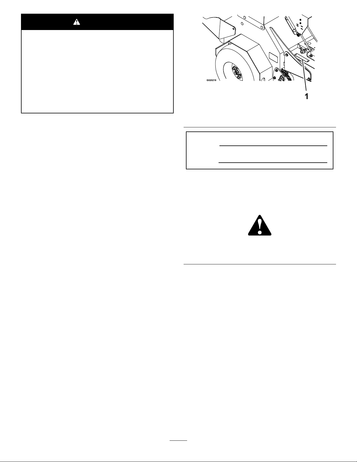
1.Locationofthemodelandserialnumbers
ModelNo.
SerialNo.
Thismanualidentiespotentialhazardsandhas
safetymessagesidentiedbythesafety-alertsymbol
(Figure2),whichsignalsahazardthatmaycause
seriousinjuryordeathifyoudonotfollowthe
recommendedprecautions.
g000502
Figure2
1.Safety-alertsymbol
Thismanualuses2wordstohighlightinformation.
Importantcallsattentiontospecialmechanical
informationandNoteemphasizesgeneralinformation
worthyofspecialattention.
YoumaycontactTorodirectlyatwww.Toro.com
forproductsafetyandoperationtrainingmaterials,
accessoryinformation,helpndingadealer,orto
registeryourproduct.
Wheneveryouneedservice,genuineToroparts,or
additionalinformation,contactanAuthorizedService
DealerorToroCustomerServiceandhavethemodel
andserialnumbersofyourproductready.Figure
1illustratesthelocationofthemodelandserial
numbersontheproduct.Writethenumbersinthe
spaceprovided.
©2017—TheToro®Company
8111LyndaleAvenueSouth
Bloomington,MN55420
Contactusatwww.Toro.com.
2
PrintedintheUSA
AllRightsReserved
Page 3

Contents
Safety.......................................................................4
SafeOperatingPractices....................................4
AeratorSafety....................................................6
SlopeIndicator...................................................7
SafetyandInstructionalDecals..........................8
Setup......................................................................12
1CheckingTirePressure..................................12
2ServicingtheBattery......................................12
3ServicingtheEngineOil.................................13
4ServicingtheTransmissionFluid....................14
5ServicingtheAuxiliaryHydraulic
Fluid..............................................................14
ProductOverview...................................................15
Controls...........................................................15
Specications..................................................18
Operation................................................................18
CheckingtheEngine-OilLevel..........................18
AddingFuel......................................................19
LubricatingtheChains......................................21
CheckingtheSafety-InterlockSystem..............22
CheckingforLooseHardware...........................22
OperatingtheMachine.....................................22
TransportingtheMachine.................................25
Maintenance...........................................................27
RecommendedMaintenanceSchedule(s)...........27
Pre-MaintenanceProcedures..............................28
PreparingfortheMachinefor
Maintenance.................................................28
AccessingtheConsoleCompartment...............28
Lubrication..........................................................29
LubricatingtheGreaseFittings.........................29
LubricatingtheCasters.....................................30
EngineMaintenance...........................................32
ServicingtheAirCleaner..................................32
ServicingtheEngineOil....................................33
ServicingtheSparkPlug...................................35
CheckingtheSparkArrester.............................36
FuelSystemMaintenance...................................36
ServicingtheFuelFilter....................................36
ElectricalSystemMaintenance...........................37
ServicingtheBattery.........................................37
ServicingtheFuses..........................................39
DriveSystemMaintenance..................................40
CheckingtheAirPressureintheTires...............40
CheckingtheWheelHubNuts..........................40
CheckingtheT orqueoftheWheelLug
Nuts..............................................................40
AdjustingtheCasterPivotBearings
Pre-Load.......................................................40
MaintainingtheChain.......................................40
CheckingtheT orqueoftheTransmission
OutputShaftNut...........................................42
BrakeMaintenance.............................................42
AdjustingtheParkingBrake..............................42
AdjustingtheBrakeSwitch...............................43
BeltMaintenance................................................43
CheckingtheConditionandTensionofthe
Belts..............................................................43
AdjustingtheAuxiliaryPump-Drive
Belt................................................................43
ReplacingtheTransmission-DriveBelt.............44
ControlsSystemMaintenance.............................45
AdjustingtheTraction-ControlLinkage.............45
HydraulicSystemMaintenance...........................46
MaintainingtheAuxiliaryHydraulic
System..........................................................46
MaintainingtheTransmission...........................47
TineMaintenance.................................................50
CheckingtheTines...........................................50
AdjustingtheTineDriveChain..........................50
Cleaning..............................................................51
CleaningtheEngineandtheExhaust
SystemArea.................................................51
RemovingtheEngineShroudsandCleaning
theCoolingFins............................................51
CleaningtheDebrisfromtheMachine...............51
WasteDisposal.................................................51
Storage...................................................................52
Troubleshooting......................................................53
Schematics.............................................................55
3
Page 4

Safety
Improperuseormaintenancebytheoperatoror
ownercanresultininjury.Toreducethepotential
forinjury,complywiththesesafetyinstructions,and
payattentiontothesafety-alertsymbol,whichmeans
Caution,Warning,orDanger—“personalsafety
instruction.”Failuretocomplywiththeinstructions
mayresultinpersonalinjuryordeath.
WARNING
Removingormodifyingoriginalequipment,
partsand/oraccessoriesmayalterthe
warranty,controllability ,andsafetyofthe
machine.Unauthorizedmodicationstothe
originalequipmentorfailuretouseoriginal
Toropartscouldleadtoseriousinjuryor
death.Unauthorizedchangestothemachine,
engine,fuelorventingsystem,mayviolate
applicablesafetyandgovernmentstandards.
Replaceallpartsincluding,butnotlimitedto,
tires,belts,andfuelsystemcomponentswith
originalT oroparts.
SafeOperatingPractices
ThefollowinginstructionsarefromANSIstandard
B71.4-2012.
Training
•ReadtheOperator'sManualandothertraining
material.
Note:Iftheoperator(s)ormechanic(s)cannot
readthemanuallanguage,itistheowner's
responsibilitytoexplainthismaterialtothem.
•Becomefamiliarwiththesafeoperationofthe
equipment,operatorcontrols,andsafetysigns.
•Alloperatorsandmechanicsshouldbetrained.
Theownerisresponsiblefortrainingtheusers.
•Neverletchildrenoruntrainedpeopleoperateor
servicetheequipment.
Note:Localregulationsmayrestricttheageof
theoperator.
•Theowner/usercanpreventandisresponsible
foraccidentsorinjuriesoccurringtohimselfor
herself,otherpeople,ordamagetoproperty.
Important:Thismachinewasmanufactured
accordingtotheappropriateregulatorystandards
ineffectatthetimeofmanufacture.Modifying
thismachineinanywaymaycauseittobe
outofcompliancewiththosestandardsand
withtheinstructionsinthisOperator’sManual.
Modicationstothismachineshouldbemade
onlybyeitherthemanufactureroranAuthorized
ServiceDealer.
Thisproductiscapableofinjuringyourhandsand
feet.Followallsafetyinstructionstoavoidserious
injuryordeath.
Theowner/usercanpreventandisresponsiblefor
accidentsorinjuriesoccurringtopeople,ordamage
toproperty.
Anyuseofthismachineotherthanaeratingturfgrass
couldprovedangeroustotheuserandbystanders.
Important:Theadditionofattachmentsmade
byothermanufacturersthatdonotmeetANSI
certicationmaycausenoncomplianceofthis
machine.
Preparation
•Evaluatetheterraintodeterminewhataccessories
andattachmentsareneededtoproperlyand
safelyperformthejob.Useonlyaccessoriesand
attachmentsapprovedbythemanufacturer.
•Wearappropriateclothing;includingsafety
glasses,longpants,substantial,slip-resistant
footwear,gloves,andhearingprotection.Tieback
longhair.Donotwearjewelry.
•Inspecttheareawhereyouwillusetheequipment
andremoveallobjectsfromtheareabeforeusing
themachine.
•Useextracarewhenhandlingfuels.Theyare
ammableanditsvaporsareexplosive.
–Useonlyanapprovedcontainer.
–Donotremovethefuelcaporaddfuelwiththe
enginerunning.Allowtheenginetocoolbefore
refueling.Donotsmokenearthemachine
whentheengineisrunning.
–Donotrefuelordrainthemachineindoors.
•Checkthattheoperator'spresencecontrols,safety
switches,andshieldsareattachedandfunctioning
properly.Donotoperatethemachineunlessthey
arefunctioningproperly.
4
Page 5

Operation
Safehandlingoffuels
•Lightningcancausesevereinjuryordeath.If
lightningisseenorthunderisheardinthearea,do
notoperatethemachine;seekshelter.
•Donotrunanengineinanenclosedarea.
•Operatethemachineonlyinwell-litareas,keeping
awayfromholesandhiddenhazards.
•Ensurethatalldrivesareinneutralandthatthe
parkingbrakeisengagedbeforestartingthe
engine.Starttheengineonlyfromtheoperator’s
position.
•Makesurethatyouhavegoodfootingwhileusing
thismachine,especiallywhenbackingup.
Note:Reducedfootingcouldcauseslipping.
•Slowdownanduseextracareonhillsides.Be
suretotravelsidetosideonhillsides.Turf
conditionscanaffectthestabilityofthemachine.
Usecautionwhileoperatingneardrop-offs.
•Slowdownandusecautionwhenmakingturns
andwhenchangingdirectionsonslopes.
•Donotoperatethemachinewithouttheshields
orotherguardssecurelyinplace.Besureall
interlocksareattached,adjustedproperly,and
functioningproperly.
•Donotchangetheenginegovernorsettingor
overspeedtheengine.
•Stoponlevelground,disengagedrives,engage
theparkingbrake(ifprovided),shutofftheengine
beforeleavingtheoperator'spositionforany
reason.
•Toavoidpersonalinjuryorpropertydamage,use
extremecareinhandlingfuel.Fuelisextremely
ammableandthevaporsareexplosive.
•Extinguishallcigarettes,cigars,pipes,andother
sourcesofignition.
•Useonlyanapprovedfuelcontainer.
•Donotremovethefuelcaporaddfuelwiththe
enginerunning.
•Allowtheenginetocoolbeforefueling.
•Donotfuelthemachineindoors.
•Donotstorethemachineorfuelcontainerwhere
thereisanopename,spark,orpilotlightsuchas
onawaterheateroronotherappliances.
•Donotllcontainersinsideavehicle,onatruck,
oronatrailerbedwithaplasticliner.Alwaysplace
containersonthegroundawayfromyourvehicle
beforelling.
•Removeequipmentfromthetruckortrailerand
fuelitontheground.Ifthisisnotpossible,
thenaddfuelwithsuchequipmentasaportable
containerratherthanfromafuel-dispensernozzle.
•Keepthenozzleincontactwiththerimofthefuel
tankorcontaineropeningatalltimesuntilfueling
iscomplete.Donotuseanozzlelock-opendevice.
•Iffuelisspilledonclothing,changeyourclothing
immediately.
•Donotoverllthefueltank.Replacethefuelcap
andtightenitsecurely.
•Stopequipmentandinspectthetinesafterstriking
objectsorifanabnormalvibrationoccurs.Make
thenecessaryrepairsbeforeresumingoperations.
•Keepyourhandsandfeetawayfromthetine
assembly.
•Lookbehindanddownbeforebackingupto
ensureaclearpath.
•Stopthemachineifanyoneentersthearea.Keep
petsandbystandersawayfromanoperating
machine.
•Slowdownandusecautionwhenmakingturns
andcrossingroadsandsidewalks.Fullyraisethe
tinesifyouarenotaerating.
•Donotoperatethemachinewhileill,tired,or
undertheinuenceofalcoholordrugs.
•Usecarewhenloadingorunloadingthemachine
intoorfromatrailerortruck.
•Usecarewhenapproachingblindcorners,shrubs,
trees,orotherobjectsthatmayobscurevision.
MaintenanceandStorage
•Donotallowuntrainedpersonneltoservicethe
machine.
•Donottouchequipmentorattachmentpartsthat
maybehotfromoperation.Allowallofthepartsof
themachinetocoolbeforeattemptingtomaintain,
adjust,orservicethemachine.
•Keepyourhandsandfeetawayfrommoving
parts.Ifpossible,donotmakeadjustmentswith
theenginerunning.
•Disengagethedrives,raisethetines,engagethe
parkingbrake,shutofftheengine,andremove
thekeyordisconnectthespark-plugwire.Waitfor
allmovementtostopbeforeadjusting,cleaning,
orrepairing.
•Disconnectthebatteryorremovethespark-plug
wirebeforemakinganyrepairs.Disconnectthe
negativeterminalrstandthepositiveterminal
last.Connectthepositiverstandnegativelast.
5
Page 6

•Usecarewhencheckingthetines.Wrapthetine(s)
orweargloves,andusecautionwhenservicing
them.Onlyreplacetines;donotstraightenorweld
them.
•Cleangrass,dirt,anddebrisfromthetines,drives,
mufers,andenginetohelppreventres.
•Cleanupoilorfuelspills.
•Parkmachineonlevel,hardground.Neverallow
untrainedpersonneltoservicethemachine.
•Usejackstandstosupportcomponentswhen
required.
•Carefullyreleasepressurefromcomponentswith
storedenergy.
•Donotstorefuelnearamesordrainthefuel
indoors.
•Lettheenginecoolbeforestoringthemachine.
•Keepallpartsingoodworkingconditionandall
hardwaretightened.Replaceallwornordamaged
decals.
Hauling
•Usecarewhenloadingorunloadingthemachine
intoatraileroratruck.
•Useafull-widthrampforloadingthemachineinto
atraileroratruck.
•Tiethemachinedownsecurelyusingstraps,
chains,cable,orropes.Bothfrontandrearstraps
shouldbedirecteddownandoutwardfromthe
machine.
AeratorSafety
Thefollowinglistcontainssafetyinformationspecic
toToroproductsandothersafetyinformationyou
mustknow.
•UseFigure3tohelpyoudeterminetheappropriate
slopeangleofareatoaerate.
•Removeormarkobstaclessuchasrocks,tree
limbs,etc.fromtheaeratingarea.
•Watchforholes,ruts,orbumps.
Note:T allgrasscanhideobstacles.
•Usecautionneardrop-offs,ditches,or
embankments.
Note:Themachinecouldsuddenlyturnoverifa
wheelgoesovertheedgeofaclifforditch,orif
anedgecavesin.
•Beawarethatoperatingonwetgrass,across
steepslopesordownhillmaycausethemachine
tolosetraction.Lossoftractiontothedrivewheels
mayresultinslidingandalossofbrakingand
steering.
•Donotaerateslopesgreaterthan15degrees.
•Avoidsuddenstartsandstopswhenaeratinguphill
becausethemachinemaytipbackward.
Note:Themachineismorestablegoinguphill
withthetinesraised.
•Keepallmovementonslopesslowandgradual.
•Donotmakesuddenchangesinspeedor
direction.
•Reducethetine-downpressuretopreventthe
drivetiresfromraisingoffthegroundandto
preventthefronttiresfromraisingofftheground
whileaeratinguphill.
•Followthemanufacturer’srecommendations
forwheelweightsorcounterweightstoimprove
stability.
•Useextracarewithattachments.
GeneralOperation
•Checkcarefullyforoverheadclearances(i.e.,
branches,doorways,electricalwires,etc.)before
operatingunderanyobjects,anddonotcontact
them.
•Usecautionwhenyouareridingontheplatform
anddrivingthemachineovercurbs,rocks,roots,
orotherobstructions.
•Donotjerkthecontrols;useasteadymotion.
•Donotcarrypassengers.
•Donotcarryequipmentonthemachine.
SlopeOperation
Useextremecautionwhenaeratingand/orturningon
slopesaslossoftractionand/ortip-overcouldoccur.
Youareresponsibleforsafeoperationonslopes.
Note:Useofattachmentscanchangethestability
ofthemachine.
Service
•Toensureoptimumperformanceandcontinued
safetycerticationofthemachine,useonly
genuineT ororeplacementpartsandaccessories.
Replacementpartsandaccessoriesmadeby
othermanufacturerscouldbedangerous,and
suchusecouldvoidtheproductwarranty.
•Neverremoveortamperwithsafetydevices.
Checktheirproperoperationregularly.Neverdo
anythingtointerferewiththeintendedfunctionofa
safetydeviceortoreducetheprotectionprovided
byasafetydevice.
•Checkthebrakeoperationfrequently.Adjustand
servicethebrakesasrequired.
6
Page 7
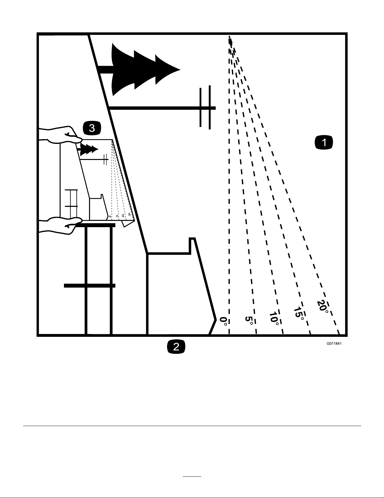
SlopeIndicator
Figure3
Thispagemaybecopiedforpersonaluse.
1.Themaximumslopeyoucansafelyoperatethemachineonis15degrees.Usetheslopecharttodeterminethedegreeofslope
ofhillsbeforeoperating.Donotoperatethismachineonaslopegreaterthan15degrees.Foldalongtheappropriateline
tomatchtherecommendedslope.
2.Alignthisedgewithaverticalsurface,atree,building,fencepole,etc.
3.Exampleofhowtocompareslopewithfoldededge
7
g011841
Page 8
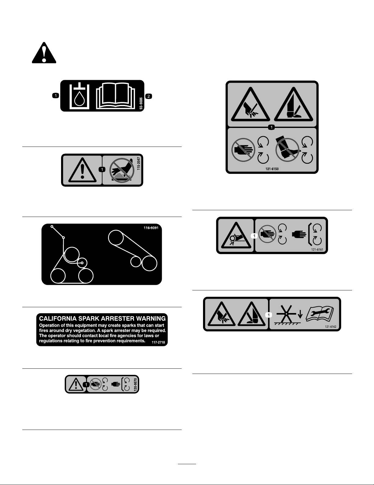
SafetyandInstructionalDecals
Safetydecalsandinstructionsareeasilyvisibletotheoperatorandarelocatednearanyarea
ofpotentialdanger.Replaceanydecalthatisdamagedormissing.
93-6686
decal93-6686
1.Hydraulicuid2.ReadtheOperator's
115-2047
1.Warning—donottouchthehotsurface.
116-9391
Manual.
decal121-6150
121-6150
decal115-2047
1.Cuttinghazardofhandandfoot—stayawayfrommoving
parts.
decal121-6161
121-6161
1.Entanglementhazard,belt—stayawayfrommovingparts;
keepallguardsinplace.
decal116-9391
117-2718
120-9570
1.Warning—stayawayfrommovingparts;keepallguards
andshieldsinplace.
decal121-6162
121-6162
decal117-2718
decal120-9570
1.Cutting/dismembermenthazardofhandorfoot—lowerthe
tinestotheground;readtheOperator’sManualforthe
disassemblyprocedure.
8
Page 9
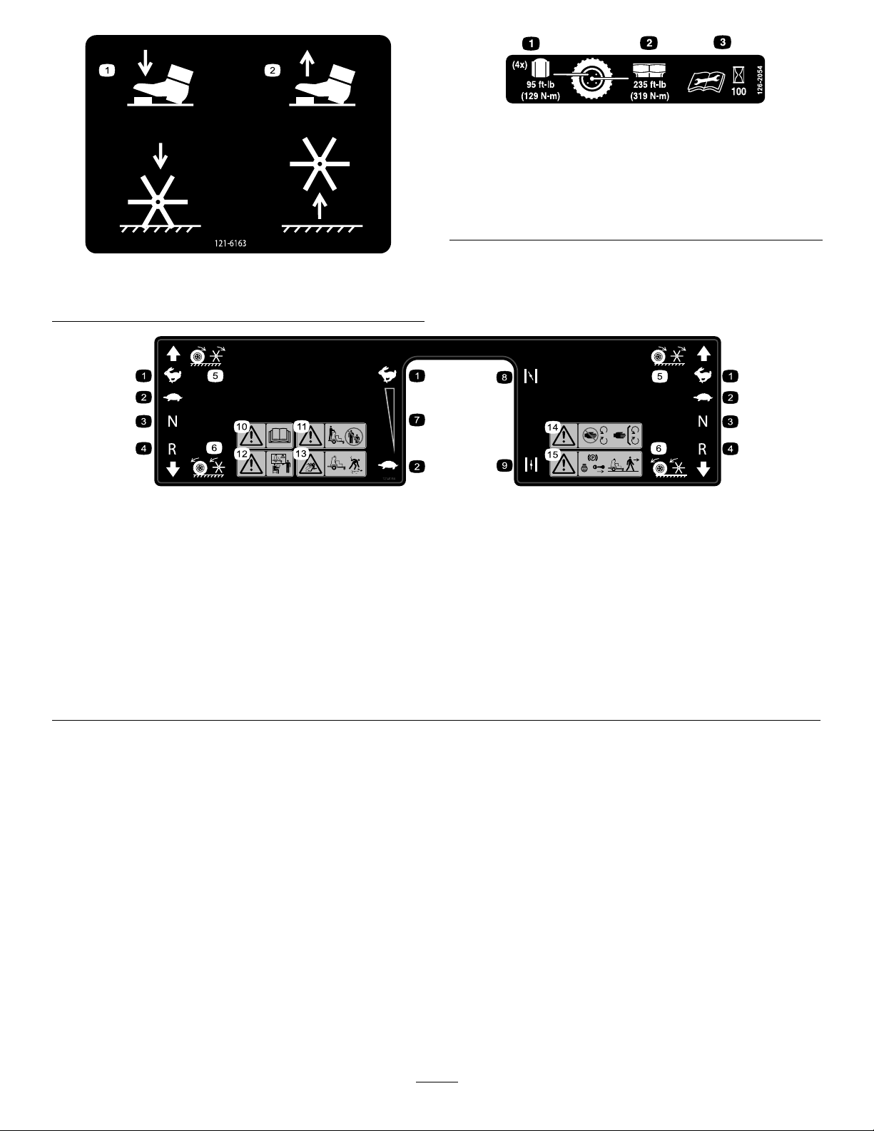
121-6163
1.Presstolowerthetines.2.Releasetoraisethetines.
decal126-2054
126-2054
1.Wheellugnuttorque129N∙m(95ft-lb)(4x)
2.Wheelhubnuttorque319N∙m(235ft-lb)
3.ReadandunderstandtheOperator’sManualbefore
performinganymaintenance;checkthetorqueevery100
hours.
decal121-6163
decal121-6164
121-6164
1.Fast6.Wheelsandtinesrotatewhenmoving
backward
2.Slow7.Continuous-variablesetting
3.Neutral
4.Reverse
5.Wheelsandtinesrotatewhenmoving
8.Choke—on
9.Choke—off14.Warning—keepawayfrommoving
10.Warning—readtheOperator’sManual.15.Warning—shutofftheengine,engage
forward
11.Warning—keepbystandersasafe
distanceawayfromthemachine.
12.Warning—donotoperatethemachine
unlessyouaretrained.
13.Thrownobjecthazard—pickupdebris
beforeoperatingthemachine.
parts;keepallguardsinplace.
theparkingbreak,andremovethekey
beforeleavingthemachine.
9
Page 10
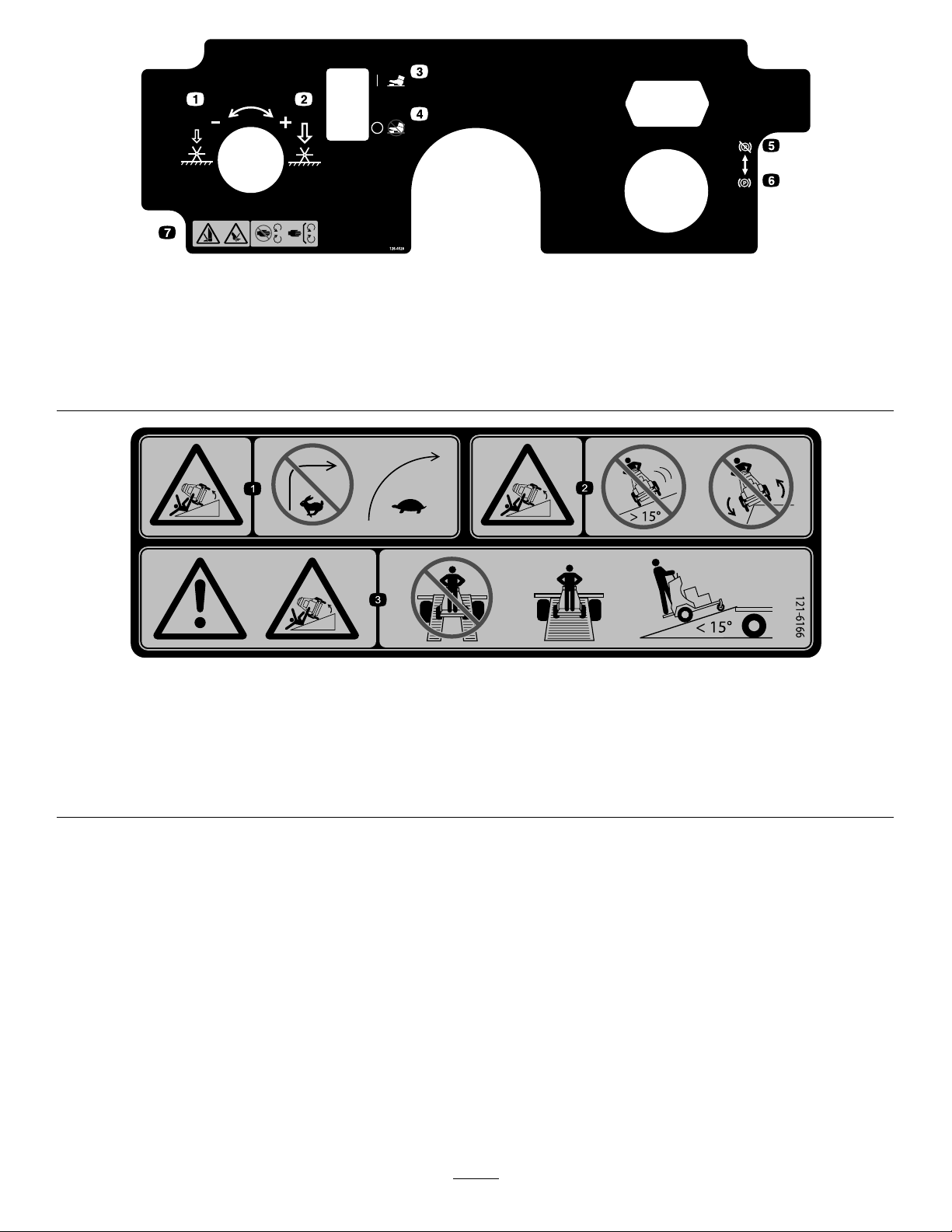
126-4528
1.Rotatecounterclockwisetodecreasepressure5.Parkingbrake—Disengaged
2.Rotateclockwisetoincreasepressure6.Parkingbrake—Engaged
3.Tineground-engagementfootswitch—On7.Cutting/dismembermenthazardofhandorfoot,tines—stay
awayfrommovingparts;keepallguardsinplace
4.Tineground-engagementfootswitch—Off
121-6166
decal126-4528
decal121-6166
1.Tippinghazard—donotturnsharplywhiletravellingfast;slow
downandturngradually.
2.Tippinghazard—donotoperatethemachineonslopes
greaterthan15degrees;donotoperatethemachinenear
drop-offs.
3.Warning;tippinghazard—donotusesplitramps;usea
full-widthramptoloadamachinefortransport;usealoading
rampatamaximumof15degrees.
10
Page 11
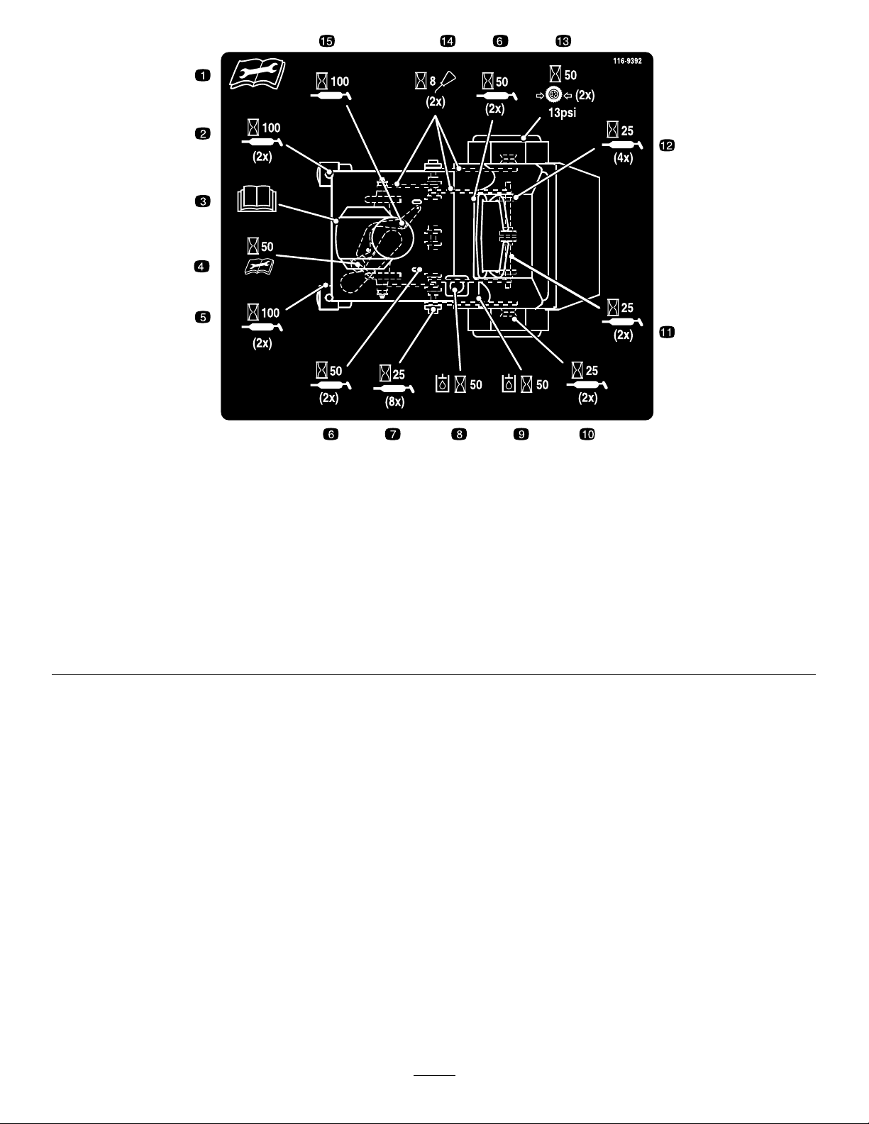
decal116-9392
116-9392
1.ReadandunderstandtheOperator’sManualbeforeservicing
9.Checktheauxiliaryhydraulictankevery50hours.
thismachine.
2.Greasethefrontcasterpivots(2x)every100hours.10.Greasethewheelbearings(2x)every25hours.
3.Refertotheengineowner’smanualforservice.11.Greasethetineassemblyidlers(2x)every25hours.
4.Checktheauxiliarypump-drivebelttensionevery50hours.12.Greasethetineshaftbearings(4x)every25hours.
5.Greasethefrontcasterwheelbearings(2x)every100hours.13.Checkthetirepressure,13psi,(2x)every50hours.
6.Greasethecontrolpivots(4x)every50hours.14.Cleanandoilthechainsandcheckthechaintension(2x)
every8hours.
7.Greasethejackshaftbearings(8x)every25hours.15.Greasethebeltidlerpivotevery100hours.
8.Checkthehydraulic-uidlevel(2x)every50hours.
11
Page 12

Setup
MediaandAdditionalParts
Description
Operator'sManual
Key2
1
CheckingTirePressure
NoPartsRequired
Procedure
1.Checkthetirepressureinthedrivetires.
Note:Properinationfordrivetiresis83to97
kPa(12to14psi).
2.Adjustthetirepressureifnecessary .
Qty.
Use
1
Readbeforeoperatingthemachine.
Startthemachine.
DANGER
Chargingorjump-startingthebatterymay
produceexplosivegases.Batterygasescan
explode,causingseriousinjury.
•Keepsparks,ames,orcigarettesaway
fromthebattery.
•Ventilatewhenchargingorusingthe
batteryinanenclosedspace.
•Makesurethattheventingpathofthe
batteryisalwaysopenoncethebatteryis
lledwithacid.
•Alwaysshieldyoureyesandfacefromthe
battery.
2
ServicingtheBattery
NoPartsRequired
Procedure
WARNING
CALIFORNIA
Proposition65Warning
Batteryposts,terminals,andrelated
accessoriescontainleadandlead
compounds,chemicalsknownto
theStateofCaliforniatocause
cancerandreproductiveharm.Wash
handsafterhandling.
DANGER
Batteryelectrolytecontainssulfuricacid,
whichispoisonousandcancausesevere
burns.Swallowingelectrolytecanbefatalor
ifittouchesskincancausesevereburns.
•Wearsafetyglassestoshieldyoureyes
andrubberglovestoprotectyourskinand
clothingwhenhandlingelectrolyte.
•Donotswallowelectrolyte.
•Intheeventofanaccident,ushwithwater
andcalladoctorimmediately.
Note:Themachineisshippedwithalled,lead-acid
battery.
12
Page 13
1.MovethekeyswitchtotheOFFpositionand
removethekey.
2.Measurethevoltageofthebatterywitha
voltmeter.
3.Usethetablebelowtolocatethechargestate
orthebattery,andifneeded,thebattery-charger
settingandchargingintervalrecommendedto
chargethebatteryto12.6Vorgreater;referto
thebatterychargetablebelow.
Important:Makesurethatthenegative
batterycableisdisconnectedandthe
batterychargerusedforchargingthebattery
hasanoutputof16Vand7Aorlessto
avoiddamagingthebattery(seechartfor
recommendedchargersettings).
BatteryChargeTable
Voltage
Reading
12.6or
greater
12.4to12.6
12.2to12.4
12.0to12.2
11.7to12.0
11.7orless
Percent
Charge
100%
75to100%
50to75%
25to50%
0to25%
0%
Maximum
Charger
Settings
16V/
7A
16V/
7A
16V/
7A
14.4V/
4A
14.4V/
4A
14.4V/
2A
Charging
Interval
Nocharging
required
30minutes
1hour
2hours
3hours
6hoursor
more
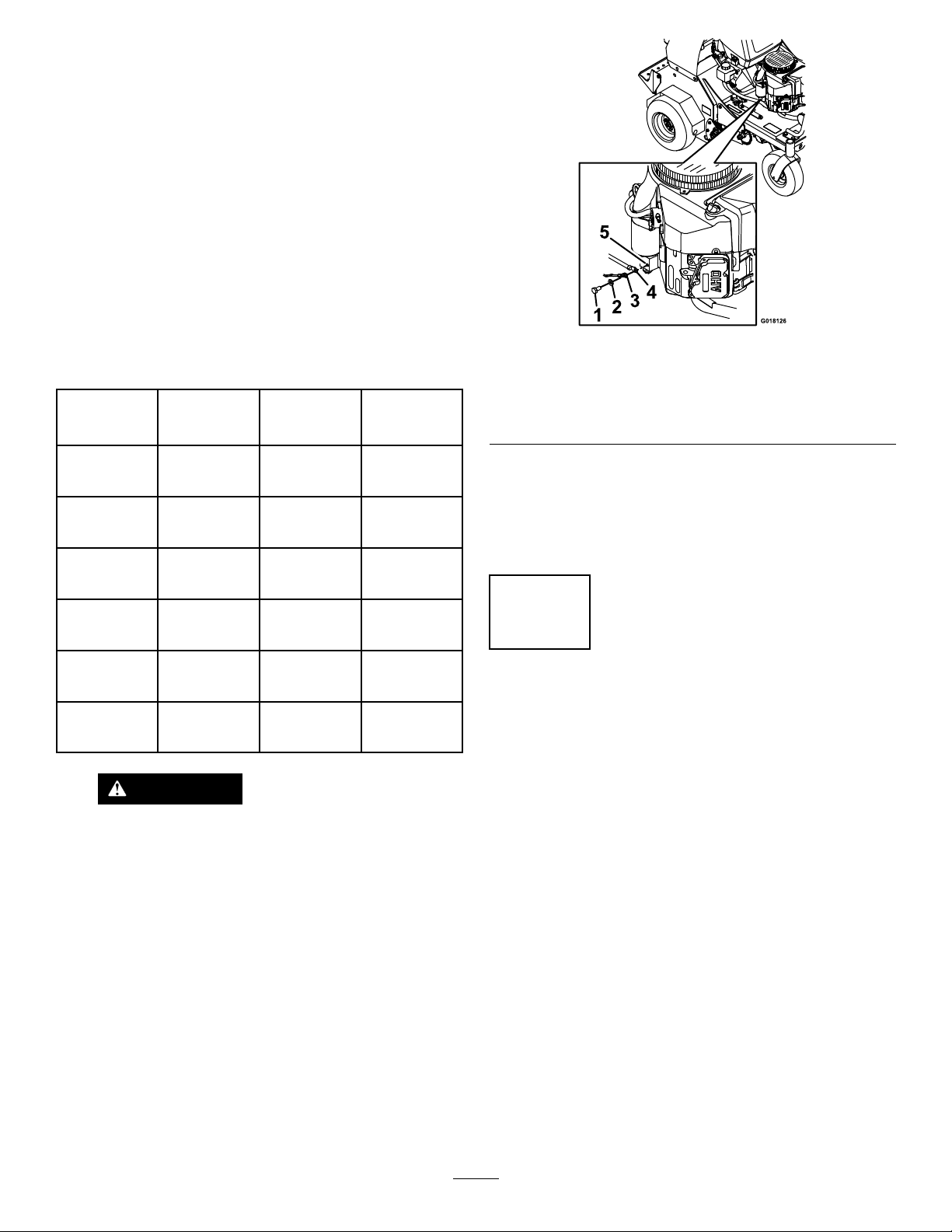
Figure4
1.Screw
2.Washer5.Engine
3.Groundwire
4.Negativebatterycable
Note:Iftimedoesnotpermitchargingthe
batteryorifchargingequipmentisnotavailable,
connectthenegativebatterycablesandrun
thevehiclecontinuouslyfor20to30minutesto
chargethebattery.
3
ServicingtheEngineOil
NoPartsRequired
g018126
CAUTION
IfthekeyswitchisintheONposition,
thereispotentialforsparksand
engagementofcomponents.Sparks
couldcauseanexplosionormoving
partscouldaccidentallyengage,causing
personalinjury .
EnsurethatthekeyswitchisintheOFF
positionbeforechargingthebattery.
4.Ifthepositivecableisalsodisconnected,
connectthepositive(red)cabletothepositive
batteryterminalandsliptheterminalcoverover
thepositiveterminal.
5.Removethescrew,washer,andgroundcable
fromtheengine.Connectthenegativebattery
cableasshowninFigure4.
Procedure
Theengineisshippedwithoil;checktheengine-oil
leveland,ifnecessary,addoiltotheappropriatelevel.
RefertoCheckingtheEngine-OilLevel(page18)for
instructionsandtheoilspecication.
13
Page 14
4
5
ServicingtheTransmission Fluid
NoPartsRequired
Procedure
Transmissionuidtype:T oroHypr-oil500
Themachineisshippedwithhydraulicuidinthe
expansiontank.
1.Runthemachineforapproximately15minutes
topurgeanyextraairoutofthehydraulic
system.
2.Shutofftheengineandallowthemachineto
cool.
3.Checkthehydraulic-uidlevelintheexpansion
tank(Figure5).
Note:Thetransmission-uidlevelshouldcover
theFullColdlinemoldedintothesideofthe
tank.
ServicingtheAuxiliary HydraulicFluid
NoPartsRequired
Procedure
Hydraulicuidtype:AW-32hydraulicuid
Note:Themachineisshippedwithhydraulicuid
inthereservoir.
1.Runthemachineforapproximately15minutes
topurgeanyextraairoutofthehydraulic
system.
2.Completelyraiseandlowerthetines3timesto
purgetheair.
3.Shutofftheengineandallowthemachineto
cool.
4.Loosenthe4boltsinsidetheframesecuringthe
padtothemachine.
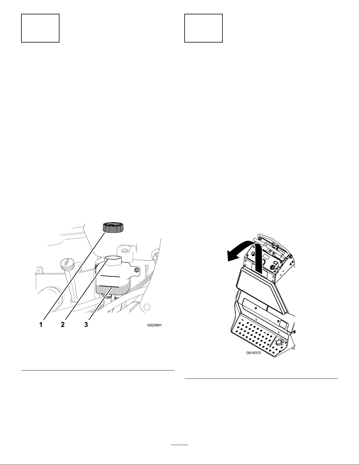
5.Liftthepadupandbacktoremoveit(Figure6).
Figure5
1.Cap3.FullColdline
2.Fillerneck(expansion
tank)
4.Ifnecessary,addthespeciedtransmissionuid
untiltheuidlevelisattheFullColdlineofthe
expansiontank(Figure5).
5.Installthecapontotheexpansiontankand
tightenthecapuntilitissnug.
Note:Donotovertightenexpansion-tank
cap.
g025891
g018375
Figure6
6.Removethecapandcheckthehydraulic-uid
levelinthereservoir(Figure7).
Note:Thehydraulic-uidlevelshouldcoverthe
wordColdthatisembossedintothebafeof
thereservoir.
14
Page 15
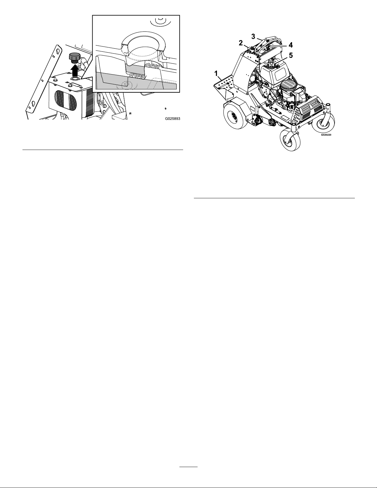
Figure7
1.Colduidlevel2.Hotuidlevel
ProductOverview
g025893
7.Ifnecessary ,addthespeciedhydraulicuidto
thereservoiruntiltheuidcoverstheColduid
levelonthebafe(Figure7).
Note:ThebafeinthereservoirislabeledHot
andCold.Fillthereservoirtotheappropriate
leveldependinguponthetemperatureofthe
uid.Theuidlevelvarieswiththetemperature
oftheuid.TheColdlevelshowsthelevelof
theuidwhenitisat24°C(75°F).TheHot
levelshowsthelevelofuidwhenitisat107°C
(225°F).
Forexample:Iftheuidisatambient-air
temperature,about24°C(75°F),llonlytothe
Coldlevel.Iftheuidisabout65°C(150°F),ll
tohalfwaybetweentheHotandColdlevels.
8.Replacethehydraulicreservoircapandtighten
ituntilsnug(Figure7).
Note:Donotovertightenthereservoircap.
9.Installthepadthatyouremovedinsteps4and
5toptheframe,andtightenthe4boltsto1978
to2542N∙cm(175to225in-lb).
Figure8
1.Platform
2.Parking-brakeknob5.Fuelcap
3.Motion-controllevers
4.Enginecontrols
Controls
Motion-ControlLevers
Themotion-controlleversarelocatedoneachsideof
thetopconsoleandcontroltheforwardandreverse
motionofthemachine.
Movetheleversforwardorbackwardtocontrolthe
drivewheelonthesamesideforwardorreverse
respectively.Thewheelspeedisproportionaltothe
amountyoumovethelever.
Important:Thetinesrotatewhenthe
motion-controlleversaremovedoutofthe
NEUTRALposition.
g020220
15
Page 16
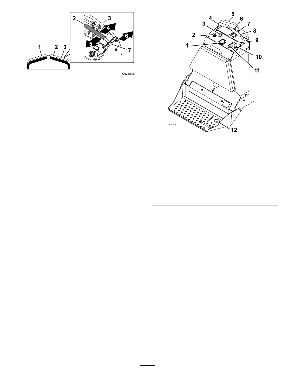
Figure9
g025895
1.Leftmotion-controllever
2.Rightmotion-controllever
3.Frontreferencebar
4.Forward
5.Reverse
6.Frontofthemachine
7.Neutral
Tine-PressureControl
Thetine-pressurecontrolislocatedontheleftsideof
thecontrolconsole(Figure10).
Usethetine-pressurecontroltoadjustthedownward
pressureonthetinesandcoredepth.Rotatethe
controlcounterclockwisetodecreasethepressure
andthelengthoftheaerationplug;rotateclockwise
toincreasepressureandincreasethelengthofthe
aerationplug.
Figure10
1.Tinedownpressuregauge
2.Tinedownpressure
control
3.On/Off-Tine
ground-engagement
footswitch
4.Leftmotion-controllever
5.Frontreferencebar
6.Throttlelever12.Tineground-engagement
7.Chokelever
8.Rightmotion-controllever
9.Hourmeter
10.Parkingbrake
11.Keyswitch
footswitch
ThrottleLever
Thethrottlelever(Figure10)islocatedonthecontrol
console(redlever).
g028268
Usethethrottlelevertocontrolenginespeed.Move
thethrottleleverforwardtoincreaseenginespeed;
movingthethrottleleverrearwardtodecreasethe
enginespeed.
Note:Movethethrottleleverforwardintothedetent
forfullthrottle.
ChokeLever
Thechokelever(Figure10)islocatedonthecontrol
console(blacklever).
Usethechokeleverisusedtoaidinstartingacold
engine.Movethechokeleverforwardtosetthe
choketotheONposition;movethechokelevertothe
rearwardtoreducethechoke.
Note:Pullthechokeleverbackintothedetenttoset
thechoketotheOFFposition.
16
Page 17
Note:Donotrunawarmenginewiththechokein
theONposition.
On/OffTineGround-Engagement
FootSwitch
Parking-BrakeHandle
Theparking-brakehandleislocatedonthecontrol
console,totherightofthekeyswitch(Figure10).
Note:Thebrakehandleengagesaparkingbrakein
eachofthetransmissions.
•T oengagetheparkingbrake,pullthehandleout
andslideitrearward.
•T oreleasetheparkingbrake,pushthehandle
forwardintothedetent.
Whenparkingonasteepslope,chockorblockthe
wheelsinadditiontoengagingtheparkingbrake.Tie
downthemachineandengagetheparkingbrake
whentransportingthemachine.
HourMeter
Thehourmeterislocatedabovethekeyswitch
(Figure10).
Thehourmeterdisplaysthetotalnumberofhours
thatyouhaverunthemachine.
Thetineground-engagementfootswitchislocated
abovethetinedownpressurecontrolonthecontrol
console.
Pushdownonthetopoftheswitchtoenablethetine
ground-engagementfootswitch.Pushdowntherear
oftheswitchtodisablethefootswitch.
Tine-PressureGauge
Thetine-pressuregaugeislocatedinthemiddleof
thecontrolconsole(Figure10).
Thetine-pressuregaugetoindicatesthedownward
pressurethemachineexertsonthetineswhen
aerating.
Tines-ElevationSwitch
Keepyourhandsandfeetawayfromthetines.
Makesurethatthetinesareaisclearofany
obstructionsbeforeloweringit.
Thetine-elevationswitchislocatedontheoperator
platform(Figure10).
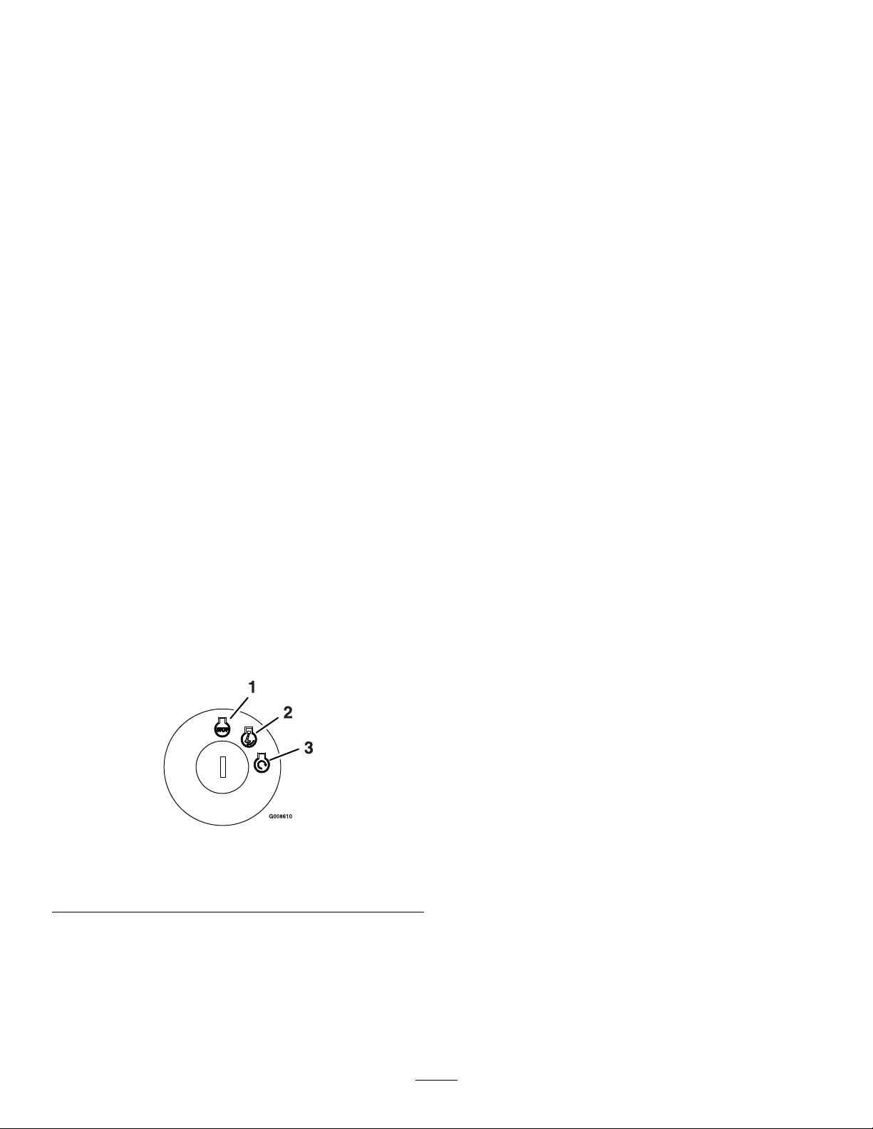
KeySwitch
Thekeyswitchislocatedontherightsideofthe
controlconsole(Figure10).
Usethekeyswitchtostartandshutofftheengine.
Theswitchhas3positions:OFF,ON,andSTART
(Figure11).
Figure11
1.OFF3.START
2.ON
Tolowerthetinesintotheground,standonthe
tine-elevationswitch.T oraisethetines,removeyour
footfromtheswitch.
Fuel-ShutoffValve
Thefuel-shutoffvalveislocatedbehindtheengine
andunderthefueltank(Figure12).
Usethefuel-shutoffvalvetoshutoffthefuelwhen
themachinewillnotbeusedforafewdays,when
transportingthemachinetoandfromthejobsite,or
whenthemachineisparkedinsideabuilding.
•T oopenforfuel-shutoffvalve,rotatethehandle
ofthefuel-shutoffvalveuntilitisalignedwiththe
fuelline.
g008610
•T oclosethefuel-shutoffvalve,rotatethehandle
90°tothefuelline.
17
Page 18
Operation
Note:Determinetheleftandrightsidesofthe
machinefromthenormaloperatingposition.
CheckingtheEngine-Oil Level
ServiceInterval:Beforeeachuseordaily
OilType:Detergentoil(APIserviceSJorhigher)
Figure12
1.OFFposition2.ONposition
Specications
Height
Length
Width
Aerationwidth
Coringrange5.1to12.7cm(2to5inches)
Weight
AselectionofToroapprovedattachmentsand
accessoriesisavailableforusewiththemachineto
enhanceandexpanditscapabilities.Contactyour
AuthorizedServiceDealerorDistributor.
Tobestprotectyourinvestmentandmaintainoptimal
performanceofyourToroequipment,countonT oro
genuineparts.Whenitcomestoreliability,T oro
deliversreplacementpartsdesignedtotheexact
engineeringspecicationofourequipment.Forpeace
ofmind,insistonTorogenuineparts.
132cm(52inches)
163cm(64inches)
121cm(48inches)
76cm(30inches)
460kg(1,015lb)
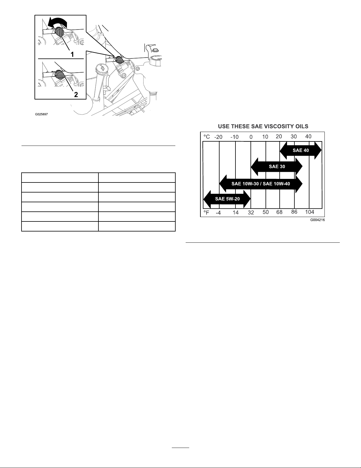
g025897
Oilviscosity:Refertothetablebelow.
g004216
Figure13
Important:Donotoperatetheenginewiththeoil
levelbelowtheLow(orAdd)markonthedipstick,
orovertheFullmark.
1.Shutofftheengine,engagetheparkingbrake,
removethekey,andwaitforallmovingpartsto
stopbeforeleavingtheoperatingposition.
2.Allowtheenginetocool.
3.Checktheengine-oillevelasshowninFigure
14.
18
Page 19

AddingFuel
Fuel-tankcapacity:18.9L(5USGallons)
•Forbestresults,useonlyclean,fresh(lessthan
30daysold),unleadedgasolinewithanoctane
ratingof87orhigher((R+M)/2ratingmethod).
g025899
•ETHANOL:Gasolinewithupto10%ethanol
(gasohol)or15%MTBE(methyltertiarybutyl
ether)byvolumeisacceptable.Ethanoland
MTBEarenotthesame.Gasolinewith15%
ethanol(E15)byvolumeisnotapprovedforuse.
Neverusegasolinethatcontainsmorethan10%
ethanolbyvolume,suchasE15(contains15%
ethanol),E20(contains20%ethanol),orE85
(containsupto85%ethanol).Usingunapproved
gasolinemaycauseperformanceproblemsand/or
enginedamagewhichmaynotbecoveredunder
warranty.
•Donotusegasolinecontainingmethanol.
•Donotstorefueleitherinthefueltankorfuel
containersoverthewinterunlessyouuseafuel
stabilizer.
Figure14
4.Iftheoillevelislow,wipeofftheareaaround
theoilllcap,removecapandaddthespecied
oiluntiltheoillevelisattheFullmarkonthe
dipstick.
•Donotaddoiltogasoline.
DANGER
Incertainconditions,fuelisextremely
ammableandhighlyexplosive.Areor
explosionfromfuelcanburnyouandothers
andcandamageproperty.
•Fillthefueltankoutdoors,inanopenarea,
andwhentheengineiscold.Wipeupany
fuelthatspills.
•Donotllthefueltankcompletelyfull.
Addfueltothefueltankuntilthelevelis6
to13mm(1/4to1/2inch)belowthebottom
ofthellerneck.Thisemptyspaceinthe
tankallowsthefueltoexpand.
•Neversmokewhenhandlingfuel,andstay
g025898
awayfromanopenameorwhereaspark
mayignitethefuelfumes.
•Storefuelinanapprovedfuelcontainer
andkeepitoutofthereachofchildren.
•Neverbuymorethana30-daysupplyof
fuel.
Note:Donotoverlltheenginewithoil.
19
Page 20

DANGER
Incertainconditionsduringfueling,static
electricitycanbereleased,causingaspark,
whichcanignitethefuelvapors.Areor
explosionfromfuelcanburnyouandothers
andcandamageproperty.
•Alwaysplacefuelcontainersontheground
awayfromyourvehiclebeforelling.
•Donotllfuelcontainersinsideavehicle
oronatruckortrailerbedbecauseinterior
carpetsorplastictruckbedlinersmay
insulatethecontainerandslowthelossof
anystaticcharge.
•Whenpractical,removefuel-powered
equipmentfromthetruckortrailerand
refueltheequipmentwithitswheelsonthe
ground.
UsingStabilizer/Conditioner
Useafuelstabilizer/conditionerinthemachineto
providethefollowingbenets:
•Keepfuelfreshduringstorageof90daysorless.
Forlongerstorage,drainthefueltank.
•Cleantheenginewhileitruns
•Eliminategum-likevarnishbuildupinthefuel
system,whichcauseshardstarting
Important:Donotusefueladditives
containingmethanolorethanol.
Addthecorrectamountoffuelstabilizer/conditioner
tothefuel.
Note:Afuelstabilizer/conditionerismost
effectivewhenmixedwithfreshfuel.T ominimize
thechanceofvarnishdepositsinthefuelsystem,
usefuelstabilizeratalltimes.
•Ifthisisnotpossible,thenrefuelsuch
equipmentonatruckortrailerfroma
portablecontainerratherthanfroma
fuel-dispensernozzle.
•Ifyoumustuseafuel-dispensernozzle,
keepthenozzleincontactwiththerimof
thefueltankorcontaineropeningatall
timesuntilfuelingiscomplete.
WARNING
Fuelisharmfulorfatalifswallowed.
Long-termexposuretovaporscancause
seriousinjuryandillness.
•Avoidprolongedbreathingofvapors.
•Keepyourfaceawayfromthenozzleand
fueltankorconditionerbottleopening.
•Avoidcontactwithskin;washoffspills
withsoapandwater.
FuelingtheMachine
1.Cleanaroundthefuel-tankcap.
2.Removethecapfromthetank.
3.Fillthefueltankwithfueltowithin6to13mm
(1/4to1/2inch)fromthetopofthetank.Donot
llintothellerneck.
Important:Donotllthetankmorethan
6mm(1/4inch)fromthetopofthetank
becausethefuelmusthaveroomtoexpand.
4.Installthefuel-tankcapandwipeupanyspilled
fuel.
20
Page 21

LubricatingtheChains
CheckingtheConditionofthe
Sprockets
ServiceInterval:Beforeeachuseordaily
1.Shutofftheengine,engagetheparkingbrake,
waitforallmovingpartstostop,andremove
thekey.
2.Inspectsprocketsforwearandreplaceas
required(Figure15).
3.Ifthechainspoporsnap;refertoAdjusting
theJackshaftDrive-ChainT ension(page40),
AdjustingtheDriveWheelChainTension(page
41),orAdjustingtheTineDriveChain(page50).
LubricatingtheChains
ServiceInterval:Beforeeachuseordaily
Important:Donotlubricatechainswith
penetratingoilorsolvents.Useoilorchain
lubricant.
1.Shutofftheengine,engagetheparkingbrake,
waitforallmovingpartstostop,andremove
thekey.
2.Raisethemachineandsupportitwithjack
standswitha460kg(1,015lb)capacity.
CAUTION
Raisingthemachineforservice
ormaintenancerelyingsolelyon
mechanicalorhydraulicjackscouldbe
dangerous.Themechanicalorhydraulic
jacksmaynotbeenoughsupportormay
malfunctionallowingthemachinetofall,
whichcouldcauseinjury .
Figure15
1.Sprockets2.Chains
CheckingtheConditionofthe
Chains
ServiceInterval:Beforeeachuseordaily
1.Shutofftheengine,engagetheparkingbrake,
waitforallmovingpartstostop,andremove
thekey.
2.Checkthechaintension(Figure15)atboth
sidesofthemachine.
Note:Thechainsshouldmoveupanddown6
to12mm(1/4to1/2inch).
Donotrelysolelyonmechanical
orhydraulicjacksforsupport.Use
adequatejackstandsorequivalent
support.
3.Starttheengineandmovethethrottlelevel
aheadtothehalf-throttleposition.
WARNING
g025984
Enginemustberunninganddrivewheels
mustbeturningsoadjustmentscanbe
performed.Contactwithmovingpartsor
hotsurfacesmaycausepersonalinjury.
Keepyourngers,hands,andclothing
clearofrotatingcomponentsandhot
surfaces.
4.Disengagetheparkingbrake.
5.Withtheenginerunning,slowlymovethe
motion-controlleversforwardandlubricateall6
chains(Figure15).
6.Checktheconditionandtensionofthechains;
refertoCheckingtheConditionoftheChains
(page21).
21
Page 22

Checkingthe
Safety-InterlockSystem
ServiceInterval:Beforeeachuseordaily
CAUTION
Ifthesafety-interlockswitchesare
disconnectedordamaged,themachinecould
operateunexpectedly,causingpersonal
injury.
•Donottamperwiththeinterlockswitches.
•Checktheoperationoftheinterlock
switchesdailyandreplaceanydamaged
switchesbeforeoperatingthemachine.
UnderstandingtheSafety-InterlockSystem
Thesafety-interlocksystemisdesignedtopreventthe
enginefromstartingunlessthemotion-controllevers
areintheneutralposition.
OperatingtheMachine
UsingtheFuel-ShutoffValve
Rotatetheleverofthefuel-shutoffvalvetoalignthe
leverwiththefuelline.
g025897
Figure16
CheckingtheSafety-InterlockSystem
1.Disconnectthespark-plugwires.
2.Whileonlevelground,blockthewheelsofthe
machinetopreventunintendedmovement.
3.Disengagetheparkingbrake.
4.Withthemotion-controlleversintheneutral
positionturnthekeytotheSTARTposition—the
startermustnotcrank.
Note:Ifthemachinedoesnotpassthistest,do
notoperatethemachine.ContactyourAuthorized
ServiceDealer.
Important:Itisessentialthattheoperator
safetymechanismsareconnectedandinproper
operatingconditionpriortouse.
CheckingforLoose Hardware
ServiceInterval:Beforeeachuseordaily
1.Shutofftheengine,engagetheparkingbrake,
removethekey,andwaitforallmovingparts
tostop.
2.Visuallyinspectmachineforanyloosehardware
oranyotherpossibleproblem.
Note:Tightenallloosehardwareorrepairthe
problembeforeoperatingthemachine.
1.OFFposition2.ONposition
StartingtheEngine
1.Movethemotion-controlleverstotheneutral
positionandengagetheparkingbrake;refer
toMotion-ControlLevers(page15)and
Parking-BrakeHandle(page17).
Note:Tostarttheengine,theparkingbrake
mustbeengaged.Itisnotnecessaryforthe
operatortobeontheplatform.
2.Placethethrottlelevermidwaybetweenthe
SLOWandFASTpositions;refertoThrottleLever
(page16).
3.Iftheengineiscold,pushthechokelever
forwardtotheONposition;refertoChokeLever
(page16).
Note:Iftheengineiswarm,pullthechokelever
totheOFFposition.
4.RotatethekeyswitchtotheSTARTposition;
refertoKeySwitch(page17).
Note:Releasetheswitchassoonastheengine
starts.
Important:Donotcranktheengine
continuouslyformorethan10secondsat
atime.Iftheenginedoesnotstart,allowa
60-secondcooldownperiodbetweenstarting
attempts.Failuretofollowtheseguidelines
canburnoutthestartermotor.
22
Page 23

5.IfthechokeleverisintheONposition,gradually
movethelevertowardtheOFFpositionasthe
enginewarmsup.
LoweringtheTines
1.SetthethrottlelevermidwaybetweentheSLOW
andFASTpositions;refertoThrottleLever(page
16).
2.Steponthetine-elevationswitchtolowerthe
tines(Figure17).
g025901
Figure18
Figure17
1.Tine-elevationswitch
3.Standontheswitchandmovethemotion-control
leversforwardtoaerate(Figure17).
4.Adjustthethrottlefortheworkingconditions;
refertoThrottleLever(page16).
AdjustingtheTineDownPressure
Important:Keepthedrivetiresonthegroundat
alltimes.
1.Tine-pressurecontrol3.Decreasepressure
2.Tine-pressuregauge
(shorterplug)
4.Increasepressure(longer
plug)
•Rotatethetine-pressurecontrol
counterclockwise(Figure18)todecrease
thedownwardpressureinordertoremovea
shorterplug.
•Rotatethetine-pressurecontrolclockwise(Figure
g025900
18)toincreasedownwardpressureinorderto
removealongerplug.
Note:Idealplugdepthis7.6to10cm(3to4inches).
Rotatethetine-pressurecontroltoadapttothesoil
conditions.
RaisingtheTines
Toraisethetines,removeyourfootfromthe
tine-elevationswitch(Figure17).
Important:Thetinesrotatewhenthe
motion-controlleverismovedoutoftheneutral
position.
Adjusttheplugdepthbyrotatingthetine-pressure
controlasfollows:
Note:Firsttimeuse:setthetine-pressurecontrol
sothatthetine-pressuregauge(Figure18)indicates
24bar(350psi).
ShuttingOfftheEngine
1.Movethemotion-controlleverstotheneutral
positionandbringthemachinetoafullstop;
refertoMotion-ControlLevers(page15).
2.Liftyourfootoffthetineground-engagement
footswitchcontroltoraisethetines;referto
RaisingtheTines(page23).
3.Placethethrottleinthemidwaybetweenthe
SLOWandFASTpositions;refertoThrottleLever
(page16).
4.Allowtheenginetorunforaminimumof15
seconds,thenturnthekeyswitchtotheOFF
positiontoshutofftheengine;refertoKey
Switch(page17).
5.Engagetheparkingbrake;refertoParking-Brake
Handle(page17).
23
Page 24

6.Removethekeytopreventchildrenorother
unauthorizedpersonsfromstartingtheengine.
7.Closethefuel-shutoffvalvewhenthemachine
willnotbeusedforafewdays,when
transporting,orwhenthemachineisparked
insideabuilding;refertoUsingtheFuel-Shutoff
Valve(page22).
DrivingtheMachine
CAUTION
Machinecanspinveryrapidlybypositioning
1levertoomuchaheadoftheother.Youmay
losecontrolofthemachine,whichmaycause
damagetothemachineorinjury.
•Usecautionwhenmakingturns.
•Slowthemachinedownbeforemaking
sharpturns.
Important:T odrivethemachine(forwardor
backward),disengagethebrakeleverbeforeyou
canmovethemotion-controllevers.
Figure19
1.Leftmotion-controllever
2.Rightmotion-controllever6.Neutral
3.Frontreferencebar
4.Frontofthemachine
5.Forward
7.Reverse
g016672
Figure20
4.T oturnleftorright,pullthemotion-controllever
backtowardneutralinthedesiredturndirection.
Thetinescanbeinthedownpositionwhen
makinggradualturns.
5.T omakezero-turns,liftyourfootoffthetine
engagementfootswitchcontroltoraisethe
tines.Theheadraisesin1second.
Important:Donotmakeazero-turnwhen
thetinesaredown,otherwiseyoumaytear
theturf.
6.T ostopthemachine,movebothmotion-control
leverstotheneutralposition.
g020241
DrivinginReverse
1.Movethemotion-controlleverstotheneutral
position.
2.T omoverearwardinastraightline,slowlymove
bothleversrearwardwithequalpressure.
DrivingForward
1.Makesurethatthemotion-controlleversarein
theneutralposition.
2.Disengagetheparkingbrake.
3.T omoveforwardinastraightline,moveboth
leversforwardwithequalpressure.
Note:Themachinemovesfasterthefarther
themotion-controlleversaremovedfromthe
neutralposition.
g016673
Figure21
24
Page 25

3.T oturnleftorright,releasepressureonthe
motion-controllevertowardthedesiredturn
direction.
LoadingtheMachineontoa
TransportVehicle
4.T omakezero-turns,liftyourfootoffthe
tine-elevationswitchtoraisethetines.Thehead
raisesin1second.
Important:Donotmakeazero-turnwhen
thetinesareinthedownposition.
5.T ostopthemachine,positionbothmotion-control
leversintheneutraloperateposition.
TransportingtheMachine
Machineweight:460kg(1,015lb)
CAUTION
Thismachinedoesnothaveproperturn
signals,lights,reectivemarkings,ora
slowmovingvehicleemblem.Drivingona
streetorroadwaywithoutsuchequipment
isdangerousandcanleadtoaccidents,
causingpersonalinjury.Drivingonastreetor
roadwaywithoutsuchequipmentmayalso
beaviolationofstatelaws,andyoumaybe
subjecttotrafcticketsand/ornes.
Donotdrivethemachineonapublicstreet
orroadway.
WARNING
Loadingthemachineontoatrailerortruck
increasesthepossibilityoftip-overandcould
causeseriousinjuryordeath.
•Useextremecautionwhenoperatinga
machineonaramp.
•Useonlyasingle,full-widthramp;donot
useindividualrampsforeachsideofthe
machine.
•Ifyoumustuseindividualramps,use
enoughrampstocreateanunbrokenramp
surfacewiderthanthemachine.
•Donotexceeda15-degreeanglebetween
rampandground,orbetweenaramp,a
trailer,oratruck.
•Avoidsuddenaccelerationwhiledriving
machineuparamptoavoidtipping
backward.
•Avoidsuddendecelerationwhilebacking
machinedownaramptoavoidtipping
backward.
Important:Donotattempttoturnthemachine
whileontheramp;youmaylosecontrolanddrive
offtheside.
•Useextremecautionwhenloadingunitsonto
trailersortrucks.
•Use1full-widthrampthatiswideenoughto
extendbeyondthereartiresinsteadofindividual
rampsforeachsideofthemachine(Figure22).
Theplatform,whendownandlockedintoposition,
mustextendbackbetweentherearwheelsand
servesasastopfortippingbackward.Havinga
full-widthrampprovidesasurfacefortheplatform
tocontactifthemachinestartstotipbackward.
Withtheplatformup,afull-widthrampprovidesa
surfacetowalkonbehindthemachine.
•Therampshouldbelongenoughsothatthe
anglesdonotexceed15degrees(Figure22).
Asteeperanglemaycausetinecomponentsto
getcaught,asthemachinemovesfromrampto
trailerortruck.Asteeperanglemayalsocause
themachinetotipbackward.Ifloadingonornear
aslope,positionthetrailerortrucksoitisonthe
downsideoftheslopeandtherampextendsup
theslope.Thisminimizestherampangle.The
trailerortruckshouldbeaslevelaspossible.
25
Page 26

TransportingtheMachine
Useaheavy-dutytrailerortrucktotransportthe
machine.Ensurethatthetrailerortruckhasall
thenecessarybrakes,lighting,andmarkingas
requiredbylaw.Pleasecarefullyreadallthesafety
instructions.
1.Raisethetinesofthemachinebeforedriving
ontothetrailerortruck.
2.Ifusingatrailer,connectittothetowingvehicle
andconnectthesafetychains.
3.Ifapplicable,connectthetrailerbrakes.
4.Loadthemachineontothetrailerortruck.
5.Shutofftheengine,removethekey,engagethe
parkingbrake,andclosethefuelvalve.
Figure22
1.Trailer3.Notgreaterthan
2.Full-widthramp
15degrees
4.Full-widthramp(sideview)
•Y oushoulddetermineifitisbesttohavethe
platformupordownwhenloading,dependingon
conditions.Ifitisnotpossibletouse1full-width
ramp,useenoughindividualrampstosimulatea
full-width,continuousramp.
•Avoidsuddenaccelerationwhendrivinguparamp
andsuddendecelerationwhenbackingdowna
ramp.Bothmaneuverscancausethemachineto
tipbackward.
g000951
6.Engagetheparkingbrakeandblockthetires.
7.Usethetie-downpointsonthemachineto
securelybindthemachinetothetrailerortruck
withstraps,chains,cable,orropes(Figure23).
Note:Refertoyourlocalordinancesforspecic
trailerandtie-downregulations.
g025949
Figure23
1.Tie-downpoints
26
Page 27

Maintenance
WARNING
Whileyouaremaintainingoradjustingthe
machine,someonecouldstarttheengine.
Accidentallystartingtheenginecould
seriouslyinjureyouorotherbystanders.
Removethekeyfromthekeyswitch,engage
parkingbrake,andpullthewire(s)offthe
sparkplug(s)beforeyoudoanymaintenance.
Alsopushthewire(s)asidesoitdoesnot
accidentallycontactthesparkplug(s).
RecommendedMaintenanceSchedule(s)
MaintenanceService
Interval
Aftertherst100hours
Beforeeachuseordaily
MaintenanceProcedure
•Changetheauxiliaryhydraulicreservoirlteranduid.
•Changethetransmissionlters.
•Fillthetransmissionwithuidwhenchangingthelter.
•Checktheengine-oillevel.
•Checktheconditionofthesprockets.
•Checktheconditionandtensionofthechains.
•Lubricatethechains.
•Checkthesafety-interlocksystem.
•Checkforloosehardware.
•Checkthetines.
•Cleantheengineandtheexhaustsystemarea(moreoftenindryordirtyconditions).
•Cleanthegrassanddebrisbuildupfromthemachine.
WARNING
Theenginecanbecomeveryhot.Touchinga
hotenginecancausesevereburns.
Allowtheenginetocoolcompletelybefore
serviceormakingrepairsaroundtheengine
area.
Every25hours
Every50hours
Every80hours
Every100hours
Every200hours
•Greasethejackshaftbearings.
•Greasethewheelbearings.
•Greasethetineshaftbearings.
•Greasethetineassemblyidlers.
•Cleanthefoamair-cleanerelement(moreofteninextremelydustyorsandy
conditions).
•Greasethecontrolpivots.
•Checksparkarrester(ifequipped).
•Checkthepressureinthetires.
•Checktheconditionandtensionofthebelts.
•Checktheauxiliaryhydraulic-uidlevel.
•Checkthehydraulictransmissionuidlevel.
•Removetheengineshroudsandcleanthecoolingns.
•Checkthepaperair-cleanerelement(moreofteninextremelydustyorsandy
conditions).
•Check,cleanandgapthesparkplug.
•Checkthebattery.
•Replacethepaperair-cleanerelement(moreofteninextremelydustyorsandy
conditions).
•Changetheengine-oillter(moreofteninextremelydustyorsandyconditions).
27
Page 28

MaintenanceService
Every250hours
Interval
MaintenanceProcedure
•Replacetheprimaryair-cleanerelement(moreofteninextremelydustyorsandy
conditions).
•Checkthesecondaryair-cleanerelement(moreofteninextremelydustyorsandy
conditions).
•Changetheauxiliaryhydraulicreservoirlteranduid.
•Changethetransmissionlters.
•Fillthetransmissionwithuidwhenchangingthelter.
Every500hours
Every800hours
Yearly
Yearlyorbeforestorage
•Replacethesecondaryair-cleanerelement(moreofteninextremelydustyorsandy
conditions).
•Replacethefuellter.
•Greasethefrontcasterpivots.
•Greasethebeltidlerpivot.
•Greasethecasterpivotsandhubs.
•Lubricatethecaster-wheelhubs.
•Lubricatethecaster-wheelhubs.
•Checkthetorqueofthewheelhubnuts.
•Checkthetorqueonthewheellugnuts.
•Checkthetorqueofthetransmissionoutputshaftnut.
•T ouchupareaswithchippedpaint.
Pre-Maintenance
Procedures
CAUTION
Raisingthemachineforserviceor
maintenancerelyingsolelyonmechanical
orhydraulicjackscouldbedangerous.The
mechanicalorhydraulicjacksmaynotbe
enoughsupportormaymalfunctionallowing
themachinetofall,whichcouldcauseinjury.
AccessingtheConsole Compartment
RemovingtheConsolePad
1.Loosenthe4anged-headboltsthatsecurethe
padtotheleftandrightconsolepanels(Figure
24).
Donotrelysolelyonmechanicalorhydraulic
jacksforsupport.Useadequatejackstands
orequivalentsupport.
PreparingfortheMachine forMaintenance
Performthefollowingbeforeservicing,cleaning,or
makinganyadjustmentstothemachine.
1.Parkthemachineonalevelsurface.
2.Shutofftheengine,engagetheparkingbrake,
waitforallmovingpartstostop.
3.Removethekeyfromthekeyswitch.
Figure24
1.Keyholeslot(console
panel)
2.Fanged-headbolt
2.Liftuptheconsolepad(Figure24)approximately
13mm(1/2inch).
3.Pulltheconsolepadstraightbackandremove
thepadfromthemachine(Figure24).
28
g025880
3.Pad
Page 29

InstallingtheConsolePad
1.Alignthe4anged-headboltsattheforward
faceoftheconsolepadtothe4keyholeslotsin
theframeoftheconsole(Figure24).
Lubrication
LubricatingtheGrease
2.Movethepadforwarduntilthepadisushto
theconsoleframe(Figure24).
3.Movethepaddownuntiltheanged-headbolts
areseatedinthekeyholeslots(Figure24).
4.Tightentheanged-headboltsto1978to2542
N∙cm(175to225in-lb).
Fittings
Greasetype:NationalLubricatingGreaseInstitute
(NGLI)grade#2multi-purposegungrease.
Note:Refertothelubricationchartforservice
intervals.
LubricationChart
Fitting
Locations
1.FrontCaster
Pivots
2.Jackshaft
Bearings
3.Wheel
Bearings
4.TineShaft
Bearings
5.Tine
AssemblyIdlers
6.Control
Pivots
7.BeltIdler
Pivot
8.FrontCaster
Hubs
Initial
Pumps
*0
1825hours
1225hours
1425hours
1225hours
1450hours
11Y early
*0
Numberof
Places
Service
Interval
2Yearly
2Yearly
Figure25
1.Shutofftheengine,engagetheparkingbrake,
waitforallmovingpartstostop,andremove
thekey.
2.Wipecleanthegreasettingswitharag(Figure
25).
29
g020222
Page 30

3.Connectagreaseguntothetting(Figure25).
4.Pumpgreaseintothettingsuntilgreasebegins
tooozeoutofthebearings.
5.Wipeupanyexcessgrease.
LubricatingtheCaster-Hubs
Bearings
ServiceInterval:Yearly
RemovingtheCaster-WheelAssembly
LubricatingtheCasters
Greasetype:NationalLubricatingGreaseInstitute
(NGLI)gradeNo.2multi-purposegungrease.
GreasingtheCasterPivots
ServiceInterval:Yearly
1.Removecapandhexplugfromthetopofthe
casterpivot(Figure26).
1.Shutofftheengine,engagetheparkingbrake,
waitforallmovingpartstostop,andremove
thekey.
2.Liftthefrontofthemachineandsupportitwith
jackstands.
3.Removethewheelnutandbolt,andremovethe
caster-wheelassemblyfromthefork(Figure27).
g025953
Figure27
1.Wheelbolt3.Wheelnut
2.Caster-wheelassembly
Figure26
1.Hexplug
2.Greasetting4.Cap
2.Threadgreasettinginhole(Figure26).
3.Pumpgreaseintothettinguntilgreaseoozes
outaroundtopbearing(Figure26).
4.Removegreasettingandinstalltheplugthat
youremovedin1(Figure26).
5.Installthecapthatyouremovedinstep1(Figure
26).
6.Repeatsteps1through5totheothercaster.
3.Casterpivot
DisassemblingtheCaster-WheelHuband
GreasingtheBearings
ServiceInterval:Yearly
g025955
Important:Usenewbearingsealswhen
lubricatingthecaster-wheelhubs.
Important:Topreventsealandbearingdamage,
checkthebearingadjustmentoften.Spinthe
castertire.Thetireshouldnotspinfreely(more
than1or2revolutions)orhaveanysideplay.If
thewheelspinsfreely,adjusttorqueonspacer
nutuntilthereisaslightamountofdrag.Apply
thread-lockingcompound.
Greasetype:NationalLubricatingGreaseInstitute
(NGLI)gradeNo.2multi-purposegungrease.
1.Removethe2sealguardsfromthewheelhub
(Figure28).
30
Page 31

Figure28
1.Axle(spacernutstill
assembled)
2.Hub5.Bearingseal
3.Bearing
4.Spacernut
6.Sealguard
2.Remove1ofthespacernutsfromtheaxle
assemblyinthecasterwheel(Figure28).
Note:Notethatthread-lockingcompoundhas
beenappliedtolockthespacernutstotheaxle
(Figure28).
3.Removetheaxle(withtheotherspacernutstill
assembledtoit)fromthecaster-wheelassembly
(Figure28).
4.Pryoutbothbearingseals(Figure28).
Note:Discardtheoldseals.
5.Removebothbearingsandinspectthemfor
wearordamage(Figure28).
Note:Replacethebearingifitiswornor
damaged.
6.Packthe2bearingswiththespeciedgrease.
AssemblingtheCaster-WheelHub
1.Install1bearingintothehubofthewheel(Figure
28).
2.Installthebearingsealintothehubatthe
bearing(Figure28).
3.Ifyouremoved(orbrokeloose)bothofthe
spacernutsfromtheaxleassembly,perform
thefollowing:
A.Cleanthethreadsoftheaxleandspacer
nut.
B.Applyathread-lockingcompoundtothe
threadsat1endoftheaxle.
C.Threadtheaxlenut,withthewrenchats
facingoutward,ontotheendoftheaxlethat
ispreparedwiththread-lockingcompound
(Figure28).
mm(1/8inch)fromtheoutersurfaceofthe
spacernuttotheendoftheaxleinsidethe
nut.
4.Inserttheassemblednutandaxleintothewheel
atthesideofthewheelwiththenewsealand
bearing(Figure28).
5.Withtheopenendofthewheelfacingup,llthe
areainsidewheelcavity(aroundtheaxle)with
thespeciedgrease.
g025954
6.Installtheotherbearingandnewsealintothe
wheel(Figure28).
7.Applyathread-lockingcompoundtothesecond
spacernutandthreaditontotheaxlewiththe
wrenchatsfacingoutward.
8.T orquethespacernutto8to9N∙m(75to80
in-lb),loosen,thentorqueit2to3N∙m(20to
25in-lb).
Note:Makesureaxledoesnotextend
beyondeithernut.
9.Installthesealguardsoverthewheelhub
(Figure28).
InstallingtheCaster-WheelAssembly
1.Aligntheholeintheaxleofthecaster-wheel
assemblybetweentheholesintheforkofthe
caster(Figure27).
2.Securethewheelassemblytotheforkwiththe
wheelnutandbolt(Figure27)thatyouremoved
instep3ofRemovingtheCaster-Wheel
Assembly(page30).
3.T orquethewheelnutto91to1 13N∙m(67to
83ft-lb).
Note:Donotthreadspacernutallofthe
wayontotheaxle.Leaveapproximately3
31
Page 32

EngineMaintenance
ServicingtheAirCleaner
ServiceInterval:Every250hours—Replacethe
primaryair-cleanerelement(more
ofteninextremelydustyorsandy
conditions).
Every250hours—Checkthesecondary
air-cleanerelement(moreofteninextremely
dustyorsandyconditions).
Every500hours—Replacethesecondary
air-cleanerelement(moreofteninextremely
dustyorsandyconditions).
Inspectthefoamandpaperelements,andreplace
themiftheyaredamagedorexcessivelydirty .
Important:Donotapplyoiltothefoamorpaper
element.
RemovingtheFoamandPaper
air-cleanerassemblyfromtheinletduct(Figure
29).
5.Carefullypullthefoamelementoffthepaper
element(Figure29).
ServicingtheFoamAir-Cleaner
Element
ServiceInterval:Every25hours(moreoften
inextremelydustyorsandy
conditions).
1.Inspecttheelementfortears,anoilylm,or
damaged(Figure29).
Important:Replacethefoamelementifit
iswornordamaged.
2.Washthefoamelementinliquidsoapand
warmwater.Whentheelementisclean,rinse
itthoroughly.
3.Drytheelementbysqueezingitinacleancloth.
Elements
1.Shutofftheengine,engagetheparkingbrake,
removethekey,andwaitforallmovingpartsto
stopbeforeleavingtheoperatingposition.
2.Cleanaroundtheaircleanertopreventdirtfrom
gettingintotheengineandcausingdamage
(Figure29).
ServicingthePaperAir-Cleaner
Element
ServiceInterval:Every100hours—Checkthe
paperair-cleanerelement(more
ofteninextremelydustyorsandy
conditions).
Every200hours—Replacethepaperair-cleaner
element(moreofteninextremelydustyor
sandyconditions).
Important:Donotwashthepaperair-cleaner
element.
1.Inspecttheelementfortears,anoilylm,or
damagetotherubberseal(Figure29).
Note:Replacethepaperelementifitis
damaged.
2.Cleanthepaperelementbygentlytappingitto
removedustanddebris.
Note:Iftheelementisverydirty ,replacethe
air-cleanerelement.
Figure29
1.Cover
2.Hoseclamp4.Foamelement
3.Rotatethecoverknobs1/4turncounterclockwise
andremovetheair-cleanercover(Figure29).
4.Rotatethethumbscrewofthehoseclamp
counterclockwiseuntilyoucanseparatethe
3.Paperelement
g012352
32
Note:Donotusepressurizedairtocleanthe
paperelement.
Page 33

InstallingtheFoamandPaper
Elements
Important:Topreventenginedamage,always
operatetheenginewiththecompletefoamand
paperair-cleanerassemblyinstalled.
1.Carefullyslidethefoamelementontothepaper
air-cleanerelement(Figure29).
2.Aligntheair-cleanerassemblyontotheinletduct
andsecureitwiththehoseclamp(Figure29).
3.Aligntheair-cleanercoverontotheenginecover
andsecurethecoverbyrotatingthecoverknobs
1/4turnclockwise(Figure29).
ServicingtheEngineOil
OilType:Detergentoil(APIserviceSJorlater)
EngineOilCapacity:1.7L(1.8USqt)withthelter
removed;1.5L(1.6USqt)withoutthelterremoved
Oilviscosity:Refertothetablebelow.
g025980
Figure31
Figure30
ChangingtheEngineOil
Note:Disposeoftheusedoilatarecyclingcenter.
1.Parkthemachinesothatthedrainsideisslightly
lowerthantheoppositesidetoassuretheoil
drainscompletely.
2.Shutofftheengine,engagetheparkingbrake,
removethekey,andwaitforallmovingpartsto
stopbeforeleavingtheoperatingposition.
3.ChangetheengineoilasshowninFigure32.
Note:Torquedrainplugto27to33N∙m(20
to24ft-lb).
g004216
g025979
Figure32
4.Slowlypourapproximately80%ofthespecied
oilintothellertube,andslowlyaddthe
additionaloiltobringittotheFullmark(Figure
33).
33
Page 34

Figure33
5.Starttheengineanddrivetoaatarea.
6.Checktheengine-oillevel.
ChangingtheEngine-OilFilter
g025976
g026005
ServiceInterval:Every200hours(moreoften
inextremelydustyorsandy
conditions).
1.Draintheoilfromtheengine;refertoChanging
theEngineOil(page33).
2.Placearagundertheoilltertosoakupany
spilledoil.
Important:Spilledoilmaydrainunderthe
engineandontotheclutch.Oilspilledon
theclutchmaydamagetheclutch,cause
thebladestostopslowlywhentheclutchis
intheOFFposition,andcausetheclutchto
slipwhentheclutchisswitchedtotheON
position.Wipeupanyspilledoil.
3.Changetheengine-oillter(Figure34).
g026006
Figure34
Note:Ensurethattheoil-ltergaskettouches
theengine,andthenturnthelteranextra3/4
turn.
4.Fillthecrankcasewiththespeciedtypeofnew
oil;refertoFigure30.
34
Page 35

ServicingtheSparkPlug
CheckingtheSparkPlug
ServiceInterval:Every100hours
TypeforallEngines:NGKBPR4ESorequivalent
AirGap:0.75mm(0.03inch)
Makesurethattheairgapbetweenthecenterand
sideelectrodesiscorrectbeforeinstallingthespark
plug.
Useasparkplugwrenchforremovingandinstalling
thesparkplug(s)andagappingtool/feelergaugeto
checkandadjusttheairgap.Installanewspark
plug(s)ifnecessary.
RemovingtheSparkPlug
1.Shutofftheengine,engagetheparkingbrake,
removethekey,andwaitforallmovingpartsto
stopbeforeleavingtheoperatingposition.
2.RemovethesparkplugasshowninFigure35.
Important:Donotcleanthesparkplug(s).
Alwaysreplacethesparkplug(s)whenithasa
blackcoating,wornelectrodes,anoilylm,or
cracks.
Ifyouseelightbrownorgrayontheinsulator,the
engineisoperatingproperly.Ablackcoatingonthe
insulatorusuallymeansthesparkplugisdirty .
Setthegapto0.75mm(0.03inch).
g027479
Figure36
InstallingtheSparkPlug
Figure35
Tightenthesparkplug(s)to22N∙m(16ft-lb).
g025981
g027478
g027735
Figure37
35
Page 36

CheckingtheSpark
FuelSystem
Arrester
MachineswithaSparkArrester
Only
ServiceInterval:Every50hours
WARNING
Hotexhaustsystemcomponentsmayignite
fuelvaporsevenaftertheengineisshut
off.Hotparticlesexhaustedduringengine
operationmayigniteammablematerials.
Firemayresultinpersonalinjuryorproperty
damage.
Donotrefuelorrunengineunlessspark
arresterisinstalled.
1.Shutofftheengine,engagetheparkingbrake,
removethekey,andwaitforallmovingpartsto
stopbeforeleavingtheoperatingposition.
2.Allowthemufertocool.
Maintenance
ServicingtheFuelFilter
ReplacingtheFuelFilter
ServiceInterval:Every800hours/Yearly(whichever
comesrst)
Note:Wipeupanyspilledfuel.
1.Shutofftheengine,engagetheparkingbrake,
removethekey,andwaitforallmovingpartsto
stopbeforeleavingtheoperatingposition.
2.Closethefuel-shutoffvalve;refertoUsingthe
Fuel-ShutoffValve(page22).
3.Squeezetheendsofthehoseclampstogether
andslidethemawayfromthelter(Figure38).
3.Checkthesparkarresterforbreaksinthe
screenorwelds.
Note:Replacethesparkarresterifitisworn
ordamaged.
4.Ifyouseethatthescreenisplugged,perform
thefollowing:
A.Removethesparkarrester.
B.Shakeloosetheparticlesfromthearrester
andcleanscreenwithawirebrush.
Note:Soakthearresterscreeninsolvent
ifnecessary.
C.Installsparkarresterontoexhaustoutlet.
g025982
Figure38
1.Hoseclamp3.Hose
2.Flowdirectionarrow(fuel
lter)
4.Removethelterfromthefuelhoses(Figure
38).
Note:Donotinstalladirtylterafteritis
removedfromthefuelline.
5.Installanewlterwiththeow-directionarrow
alignedasillustratedinFigure38.
Note:Ensurethatthefuelhosesarefully
seatedontothehosettingsofthefuellter.
6.Alignthehoseclampsoverthehoseandthe
fuel-lterttings(Figure38).
36
Page 37

7.Openthefuel-shutoffvalve;refertoUsingthe
Fuel-ShutoffValve(page22).
ElectricalSystem
8.Checkforfuelleaksandrepairifneeded.
9.Wipeupanyspilledfuel.
Maintenance
ServicingtheBattery
ServiceInterval:Every100hours
Alwayskeepthebatterycleanandfullycharged.Use
apapertoweltocleanthebatterycase.Ifthebattery
terminalsarecorroded,cleanthemwithasolutionof
4partswaterand1partbakingsoda.Applyalight
coatingofgreasetothebatteryterminalstoprevent
corrosion.
Voltage:12V
WARNING
CALIFORNIA
Proposition65Warning
Batteryposts,terminals,andrelated
accessoriescontainleadandlead
compounds,chemicalsknownto
theStateofCaliforniatocause
cancerandreproductiveharm.Wash
handsafterhandling.
DANGER
Batteryelectrolytecontainssulfuricacid,
whichisfatalifconsumedandcausessevere
burns.
Donotdrinkelectrolyte,andavoidcontact
withskin,eyes,andclothing.Wearsafety
glassestoshieldyoureyesandrubbergloves
toprotectyourhands.
37
Page 38

RemovingtheBattery
WARNING
Batteryterminalsormetaltoolscouldshort
againstmetalmachinecomponents,causing
sparks.Sparkscancausethebatterygasses
toexplode,resultinginpersonalinjury.
•Whenremovingorinstallingthebattery,
donotallowthebatteryterminalstotouch
anymetalpartsofthemachine.
•Donotallowmetaltoolstoshortbetween
thebatteryterminalsandmetalpartsofthe
machine.
WARNING
Incorrectbattery-cableroutingcoulddamage
themachineandcables,causingsparks.
Sparkscancausethebatterygassesto
explode,resultinginpersonalinjury.
•Alwaysdisconnectthenegative(black)
batterycablebeforedisconnectingthe
positive(red)cable.
•Alwaysconnectthepositive(red)battery
cablebeforeconnectingthenegative
(black)cable.
1.Shutofftheengine,engagetheparkingbrake,
removethekey,andwaitforallmovingpartsto
stopbeforeleavingtheoperatingposition.
2.Removetheconsolepad;refertoRemovingthe
ConsolePad(page28).
3.Onthebattery,lifttheblackterminalcoverfrom
thenegativecable(Figure39).
Figure39
1.Flangedbolt
2.Terminalcover
(black—negativebattery
terminal)
3.Terminalcover
(red—positivebattery
terminal)
4.Positive(+)battery
terminal
4.Disconnectthenegativebatterycablefromthe
negative(-)batteryterminal,andremovethe
cablefromthebattery(Figure39).
5.Slidetheredterminalcoveroffthepositive
batteryterminal(Figure39).
6.Disconnectthepositive(red)batterycable,and
removethecablefromthebattery(Figure39).
7.Removethehookofthebatterystrapfromthe
batterytray(Figure39),andremovethebattery.
5.Negative(-)battery
terminal
6.Flangednut
7.Batterytray
8.Batterystrap
g025881
InstallingtheBattery
1.Placethebatteryontothemachine(Figure39).
2.Securethebatterytothebatterytraywiththe
batterystrap.
3.Installthepositive(red)batterycabletopositive
(+)batteryterminalwithaangedboltand
angednut(Figure39).
4.Slidetheredterminalcoveroverthe
positive-batteryterminal.
5.Installthenegativebatterycableandtheground
wiretothenegative(-)batteryterminalwitha
angedboltandangednut(Figure39).
6.Slidetheblackterminalcoveroverthe
negative-batteryterminal.
38
Page 39

ChargingtheBattery
ServicingtheFuses
WARNING
Chargingthebatteryproducesgassesthat
canexplode.
Neversmokenearthebatteryandkeepsparks
andamesawayfromthebattery.
Important:Alwayskeepthebatteryfullycharged
(1.265specicgravity)topreventbatterydamage
whenthetemperatureisbelow0°C(32°F).
1.Removethebatteryfromthechassis;referto
RemovingtheBattery(page38).
2.Checktheelectrolytelevel.
3.Ensurethatthellercapsareinstalledonthe
battery.
4.Chargethebatteryfor1hourat25to30Aor6
hoursat4to6A.
5.Whenthebatteryisfullycharged,unplugthe
chargerfromtheelectricaloutlet,anddisconnect
thechargerleadsfromthebatteryposts(Figure
40).
Theelectricalsystemisprotectedbyfuses,and
requiresnomaintenance.Ifafuseblows,checkthe
componentorcircuitforamalfunctionorshort.
1.Releasethecushionfromtherearofthe
machine.
2.Removethenegative-batterycablefromthe
batteryterminal;refertosteps4and5of
RemovingtheBattery(page38).
Note:Ensurethatthenegativebatterycable
doesnottouchthebatteryterminal.
3.Pullthefusefromthesocketofthefuseblock
(Figure41).
6.Installthebatteryontothemachineandconnect
thebatterycables;refertoInstallingtheBattery
(page38).
Note:Donotrunthemachinewiththebattery
disconnected;electricaldamagemayoccur.
Figure40
1.Positivebatterypost
2.Negativebatterypost
3.Red(+)chargerlead
4.Black(-)chargerlead
g025983
Figure41
1.Fuseblock
4.Installafuseofthesametypeandamperesinto
thesocketofthefuseblock(Figure41).
5.Installthenegative-batterycablefromthebattery
terminal;refertosteps5and6ofInstallingthe
g000538
Battery(page38).
39
Page 40

DriveSystem
AdjustingtheCasterPivot
Maintenance
CheckingtheAirPressure intheTires
ServiceInterval:Every50hours
Note:Thesemi-pneumaticcastertiresdonotneed
tobeinated.
1.Shutofftheengine,engagetheparkingbrake,
removethekey,andwaitforallmovingpartsto
stopbeforeleavingtheoperatingposition.
2.Checkthepressureofthedrivetires.
3.Inatethedrivetiresto83to97kPa(12to14
psi).
CheckingtheWheelHub Nuts
ServiceInterval:Yearly
Torquethewheelhubnuts(Figure42)to285to350
N∙m(210to260ft-lb).
Note:Donotuseanti-seizecompoundonthewheel
hub.
BearingsPre-Load
Note:Ifyoudisassemblethecasterpivotbearings,
ensurethatthespring-discwashersareinstalledas
showninFigure43.
1.Removedustcapfromcasterhub(Figure43).
Figure43
1.Dustcap
2.Locknut
3.Spring-discwashers
4.Spindle
5.Casterhub
g026022
Figure42
1.Lugnut2.Hubnut
CheckingtheTorqueofthe WheelLugNuts
ServiceInterval:Yearly
Torquethewheellugnuts(Figure42)to122to129
N∙m(90to95ft-lb).
2.Tightenthelocknutclockwiseuntilthe
spring-discwashersareat(Figure43).
3.Rotatethelocknutcounterclockwise1/4turn
(Figure43).
4.Installthedustcap(Figure43).
MaintainingtheChain
AdjustingtheJackshaft
g026029
Drive-ChainTension
1.Shutofftheengine,engagetheparkingbrake,
removethekey,andwaitforallmovingpartsto
stopbeforeleavingtheoperatingposition.
2.Lifttherearofthemachineandsupportitusing
jackstandsorequivalentsupport.
3.Checkthechainsonbothsidesofthemachine
forpropertension.
Note:Thechainsshouldmoveupanddown6
to12mm(1/4to1/2inch).
4.Ateachsideofthemachine,loosenthe3nuts
andboltsthatsecurethetransmissionmount
andtensionerplate,andthe2nutssecuringthe
40
Page 41

adjustmentboltatthetensionerplateasshown
inFigure44.
Note:Youmustloosenthenutsandboltsthat
securethetransmissionmountandtensioner
plateatbothsidesofthemachine.
AdjustingtheDriveWheelChain
Tension
1.Shutofftheengine,engagetheparkingbrake,
removethekey,andwaitforallmovingpartsto
stopbeforeleavingtheoperatingposition.
2.Lifttherearofthemachineandsupportitusing
jackstands.
3.Checkthetensionofthedrive-wheelchains
(Figure45).
Note:Thechainsshouldmoveupanddown6
to12mm(1/4to1/2inch).
Figure44
1.Hydromountingboltsand
nuts
2.Nuts
3.Adjustmentbolt
4.6to12mm(1/4-1/2inch)
5.Guardremovedforclarity
5.Turntheadjustmentbolttomovetransmission
adjustmentplatesandtransmission.
6.Whenthechainscanmoveupanddown6to12
mm(1/4to1/2inch),tightenthenutsonboth
sidesoftheadjustmentbolts.
7.Tightennutsandboltsthatsecurethehydro
mounting.
8.Adjustthetraction-controllinkage,referto
AdjustingtheTraction-ControlLinkage(page
45).
g025990
Figure45
1.Locknut3.Drive-wheelchain
2.Idlersprocket
g020261
4.Loosenthelocknutandcarriageboltthatsecure
theidlersprocket(Figure45).
5.Increaseordecreasechaintensionby
performingthefollowing:
•Pushdownandforwardonthesprocket
toincreasethechaintensionasshownin
Figure45.
•Liftupandbackonthesprockettodecrease
thechaintension.
6.T orquethelocknutto91to113N∙m(67to83
ft-lb).
7.Checkthechaintensionandifnecessaryrepeat
steps4through6untilyoucanmovethechain
upanddown6to12mm(1/4to1/2inch).
41
Page 42

CheckingtheTorqueofthe
TransmissionOutputShaft
BrakeMaintenance
Nut
ServiceInterval:Yearly
Torquethenut(Figure46)onthetransmissionoutput
taperedshaftto285to353N∙m(210to260ft-lb).
Figure46
1.Transmissionoutputshaftnut
AdjustingtheParking Brake
Iftheparkingbrakedoesnotholdsecurely,an
adjustmentisrequired.
1.Parkthemachineonalevelsurface.
2.Shutoffengineandwaitforallmovingpartsto
stop.
3.Checktheairpressureinthedrivetires.
Note:Ifneeded,adjusttotherecommended
ination;refertoCheckingtheAirPressurein
theTires(page40).
4.Loosenthejamnutonthebrakecableunder
theconsole(Figure47).
g025989
Figure47
1.7.9cm(3-1/8inch)
5.Engagetheparkingbrake(Figure47).
6.Adjustthejamnutpositionuntil7.9cm(3-1/8
inch)fromthebottomofthelinktothebottomof
thespring(Figure47).
7.Securetheadjustmentofthecablebytightening
thejamnuts(Figure47).
8.Checktheparkingbrake;ifnecessary,repeat
steps4through7.
42
g025991
Page 43

AdjustingtheBrakeSwitch
1.Parkthemachineonalevelsurface.
BeltMaintenance
2.Shutofftheengineandwaitforallmovingparts
tostop.
3.Priortheadjustingthebrakeswitchensurethat
theparkingbrakeisproperlyadjusted;referto
AdjustingtheParkingBrake(page42).
4.Engagetheparkingbrake.
5.Checkthedistancebetweentheparking
brake-switchbrackettothebrakearmofthe
transmission(Figure48).
Note:Thedistanceshouldbe3.2mm(1/8
inch).
CheckingtheCondition andTensionoftheBelts
ServiceInterval:Every50hours
1.Shutofftheengine,engagetheparkingbrake,
removethekey,andwaitforallmovingpartsto
stopbeforeleavingtheoperatingposition.
2.Raisethemachineandsupportitwithjack
standswitha460kg(1,015lb)capacity.
3.Checktheauxiliarypump-drivebeltcondition
andtension(Figure49).
Note:Thebeltshoulddeect1.3cm(1/2inch)
when1.4kg(3lb)offorceisappliedtothebelt
midwaybetweentheauxiliarypumpandengine
pulleys.Ifthebelttensionistoohighortoolow,
refertoAdjustingtheAuxiliaryPump-DriveBelt
(page43).
4.Checkconditionofthetransmission-drivebelt
(Figure49).
Note:Thetransmissionbelthasa
automatic-springtensioner.
Figure48
1.Brakearm(transmission)
2.Plunger(brakeswitch)5.Carriagebolt
3.Brake-switchbracket
6.Ifadjustmentisrequired,preformthefollowing:
A.Loosenthelocknutandcarriagebolt
securingtheparkingbrakeswitchbracket
(Figure48).
B.Adjustthepositionofthebrake-switch
bracketuntilthegap(Figure48)between
theswitchbracketandthebrakearmis3.2
mm(1/8inch)
C.Tightenthelocknutandcarriagebolt(Figure
48)securingthebrake-switchbracketto
1017to1243N∙cm(90to110in-lb).
4.Locknut
g025992
g025994
Figure49
1.Transmission-drivebelt2.Auxiliarypump-drivebelt
AdjustingtheAuxiliary Pump-DriveBelt
1.Shutofftheengine,engagetheparkingbrake,
removethekey,andwaitforallmovingpartsto
stopbeforeleavingtheoperatingposition.
2.Loosenthelocknut(3/8inch)thatsecuresthe
auxiliarypump-idlerpulleytothechassisofthe
machine.
43
Page 44

Figure50
g025997
1.Auxiliarypump
2.Auxiliarypump-idlerpulley5.Auxiliarypump-drivebelt
3.Locknut(3/8inch)
4.Adjustmentslot(chassis)
3.Adjustthebelttensionasfollows:
•Movetheauxiliarypump-idlerpulley
rearwardandoutwardtotightenthebelt.
•Movetheauxiliarypump-idlerpulleyforward
andinwardtoloosenthebelt.
Note:Thebeltshoulddeect1.3cm(1/2inch)
when1.4kg(3lb)offorceisappliedtothebelt
midwaybetweentheauxiliarypumpandengine
pulleys.
4.Tightenlocknutto37to45N∙m(27to33ft-lb).
Replacingthe Transmission-DriveBelt
Note:Noadjustmentsarerequiredforbelttension.
1.Shutofftheengine,engagetheparkingbrake,
removethekey,andwaitforallmovingpartsto
stopbeforeleavingtheoperatingposition.
2.Insertabreakerbarintothesocketofthe
belt-tensionbracketandmovethebracket
outwardandforward(Figure51).
g025999
Figure51
1.Transmissionpulley4.Enginepulley
2.Transmission5.T ensionerpulley
3.Socket(belt-tension
bracket)
3.Slipthetransmission-drivebeltoftheengine,
tensioner,andtransmissionpulleys(Figure51).
4.Routethenewtransmission-drivebeltaround
theengine,tensioner,andtransmissionpulleys
asshowninFigure51
5.Releasethebelt-tensionbracketandallowthe
springtotensionthebelt(Figure51).
Note:Makesurethatthebelt-tensionbracket
andpulleycanmovefreely.
44
Page 45

ControlsSystem
betweenthecontrolleverandthefront
referencebar.
Maintenance
Adjustingthe Traction-ControlLinkage
1.Parkthemachineonalevelsurface.
2.Shutofftheengine,engagetheparkingbrake,
removethekey,andwaitforallmovingpartsto
stopbeforeleavingtheoperatingposition.
3.Pushthecontrolleverallthewayforwardtothe
frontreferencebar.
4.Ifthecontrollevercontactthereferencebar
ordonotcontactthereferencebarperform
thefollowing:
A.Releasethecontrolleverandallowitto
returntotheneutralposition.
B.Removethespring-clevispinfromthefork
ttingofthetraction-controllinkage(Figure
52).
F.Removethespring-clevispin,rotatethe
turnbuckleclockwise1additionalturn,and
insertthespring-clevispin(Figure52).
5.Repeatsteps4Athrough4Ffortheother
traction-controllinkage.
Figure52
1.Spring-clevispin
2.Locknut
C.Adjusttheforkttingtosettheinitialgap
asfollows:
3.Turnbuckle
•Ifthecontrollevercontactsthe
referencebar,rotatetheforktting
(Figure52)counterclockwise(asviewed
fromthetopofthemachine).
•Ifthecontrolleverdoesnotcontacts
thereferencebar,rotatetheforktting
(Figure52)counterclockwise.
D.Installthespringclevispin(Figure52)and
movethecontrolleverforward.
E.RepeatthisstepsAthroughDuntilthere
isagapapproximately1.6mm(1/16inch)
g020223
45
Page 46

HydraulicSystem
Maintenance
MaintainingtheAuxiliary HydraulicSystem
Hydraulicuidtype:AW-32hydraulicuid
CheckingtheAuxiliary
leveldependinguponthetemperatureofthe
uid.Theuidlevelvarieswiththetemperature
oftheuid.TheColdlevelshowsthelevelof
theuidwhenitisat24°C(75°F).TheHot
levelshowsthelevelofuidwhenitisat107°C
(225°F).
Forexample:Iftheuidisatambient-air
temperature,about24°C(75°F),llonlytothe
Coldlevel.Iftheuidisabout65°C(150°F),ll
tohalfwaybetweentheHotandColdlevels.
8.Replacethehydraulicreservoircapandtighten
ituntilitissnug(Figure53).
Hydraulic-FluidLevel
ServiceInterval:Every50hours
1.Parkthemachineonalevelsurface.
2.Lowerthetinestotheground.
3.Shutofftheengine,engagetheparkingbrake,
removethekey,andwaitforallmovingpartsto
stopbeforeleavingtheoperatingposition.
4.Removetheconsolepad;refertoRemovingthe
ConsolePad(page28).
5.Cleantheareaaroundthehydraulicreservoir
cap(Figure53).
Note:Donotovertightenthereservoircap.
9.Installtheconsolepad;refertoRemovingthe
ConsolePad(page28).
ChangingtheAuxiliaryHydraulic
ReservoirFluidandFilter
ServiceInterval:Aftertherst100hours
Every250hoursthereafter
1.Shutofftheengine,engagetheparkingbrake,
removethekey,andwaitforallmovingpartsto
stopbeforeleavingtheoperatingposition.
2.Carefullycleanareaaroundthefrontofthe
auxiliarypump,llcapforthereservoir,andlter
(Figure54).
Important:Ensurethatnodirtor
contaminationentershydraulicsystem.
Figure53
1.Colduidlevel2.Hotuidlevel
6.Removethecapandcheckhydraulic-uidlevel
inthereservoir(Figure53).
Note:Thehydraulic-uidlevelshouldcoverthe
wordColdthatisembossedintothebafeof
thereservoir.
7.Ifnecessary,addthespeciedhydraulicuidto
thereservoiruntiltheuidcoverstheColduid
levelonthebafe(Figure53).
Note:ThebafeionthereservoirislabeledHot
andCold.Fillthereservoirtotheappropriate
g025893
g026008
Figure54
46
Page 47

3.Atthefrontoftheauxiliaryhydraulicpump,
removetheinlethosefromthehydraulictting
inthepump,placetheendofthehoseinadrain
container,andallowtheuidtodrain(Figure55).
Figure55
9.Addthespecieduiduntilthelevelreachesthe
Coldlllinelocatedonthereservoirtank;refer
toCheckingtheAuxiliaryHydraulic-FluidLevel
(page46).
10.Starttheengineandraiseandlowerthetines.
11.Lowerthetinestothegroundandrellthe
reservoirtotheColdllline.
Maintainingthe Transmission
Transmissionuidtype:T oro®HYPR-OIL™500
hydraulicuidorMobil®115W-50syntheticmotoroil.
Important:Usethespecieduid.Otheruids
g026010
couldcausesystemdamage.
1.Hydraulictting(auxiliary
hydraulicpump)
2.Inlethose
3.Draincontainer
4.Cleanaroundthettingforthehydraulicpump.
5.Rotatetheauxiliaryhydrauliclter
counterclockwiseandremoveitfromthe
baseofthelteradapter(Figure56).Allowthe
uidtodrain.
CheckingtheTransmissionFluid
Level
ServiceInterval:Every50hours
1.Shutofftheengine,engagetheparkingbrake,
removethekey,andwaitforallmovingpartsto
stopbeforeleavingtheoperatingposition.
2.Allowthemachinetocool.
3.Removethecapfromtheexpansiontankand
checkthehydraulic-uidlevelinthetank(Figure
57).
Note:Thetransmissionuidlevelshouldcover
theFullColdlinemoldedintothesideofthe
tank.
Figure56
1.Auxiliaryhydrauliclter
2.Filteradapter
6.Applyathincoatofspecieduidontotheseal
ofthenewhydrauliclter.
7.Installthelterbyrotatingitclockwiseontothe
lteradapteruntilthesealcontactsthelter
adapter,thentightenthelteranadditional2/3
to3/4turn(Figure56).
8.Installtheinlethoseontothettinginthepump
andtorquethehosettingto50N∙m(37ft-lb).
g026007
g025891
Figure57
1.Cap3.FullColdline
2.Fillerneck(expansion
tank)
47
Page 48

4.Ifnecessary,addthespeciedtransmissionuid
untiltheuidlevelisattheFullColdlineofthe
expansiontank(Figure57).
5.Replaceexpansion-tankcapandtightenituntil
snug.
Note:Donotovertightentheexpansion-tank
cap.
ChangingtheTransmissionFilters
ServiceInterval:Aftertherst100hours
Every250hoursthereafter
Note:Donotchangethehydraulicsystemuid
(exceptforwhatcanbedrainedwhenchanginglter),
unlesstheuidhasbeencontaminatedorbeen
extremelyhot.
1.Shutofftheengine,engagetheparkingbrake,
removethekey,andwaitforallmovingpartsto
stopbeforeleavingtheoperatingposition.
2.Raisethemachineandsupportitwithjack
standswitha460kg(1,015lb)capacity.
3.Removethe3washer-headbolts(1/4x3/4inch)
thatsecurethelterguardtothetransmission,
andremovetheguard(Figure58).
7.Applyathincoatofspecieduidontotheseal
ofthenewtransmissionlter.
8.Installthelterbyrotatingitclockwiseontothe
lteradapteruntilthesealcontactsthebaseof
theadapter,thentightenthelteranadditional
3/4to1turn(Figure58).
9.Installthelterguardwiththe3washer-head
bolts(1/4x3/4inch)thatyouremovedinstep3
(Figure58),andtightentheboltsto1 117to1243
N∙cm(90to110in-lb).
FillingtheTransmissionswith
Fluid
ServiceInterval:Aftertherst100hours
Every250hoursthereafter
1.Raisetherearofmachineupandsupportwith
jackstands(orequivalentsupport)justhigh
enoughtoallowthedrivewheelstoturnfreely.
CAUTION
Raisingthemachineforservice
ormaintenancerelyingsolelyon
mechanicalorhydraulicjackscouldbe
dangerous.Themechanicalorhydraulic
jacksmaynotbeenoughsupportormay
malfunctionallowingthemachinetofall,
whichcouldcauseinjury .
Figure58
1.Transmission
2.Filteradapter5.Filterguard
3.Transmissionlter
4.Cleanthearoundthetransmissionlter(Figure
58).
5.Alignadrainpanunderthelter.
6.Rotatetheltercounterclockwiseandremove
thelter(Figure58).
4.Washer-headbolts(1/4x
3/4inch)
Note:Allowtheuidtocompletelydrainfrom
thelteradapterofthetransmission.
Donotrelysolelyonmechanical
orhydraulicjacksforsupport.Use
adequatejackstandsorequivalent
support.
2.Alignadrainpanunderthesightplugsofthe
transmissions(Figure59andFigure60).
g026014
48
Page 49

1.Sightplug
2.Sight-plugport
Figure59
Lefttransmissionshown
8.Starttheengineandmovethethrottlemidway
betweentheSLOWandFASTpositions
9.Disengagetheparkingbrake.
10.Slowlymovethemotion-controlleversinthe
forwardandreversedirections5to6times.
Note:Cyclingthetraction-controlsforwardand
reversepurgesairfromthetransmissions.
11.Shutofftheengineandremovethekey.
12.Checktheuidlevelintheexpansiontank,
andaddthespecieduidasrequired;referto
g026015
CheckingtheTransmissionFluidLevel(page
47).
13.Repeatsteps8through12untilalltheairis
completelypurgedfromthetransmissions.
3.Up
Note:Theairispurgedwhenthetransmissions
whenthetransmissionsoperateatnormalnoise
levelsandsmoothlymoveforwardandreverse
atnormalspeeds.
14.Lowerthemachineandremovethejackstands.
Figure60
Lefttransmissionshown
1.Sightplug
2.Sight-plugport
3.Up
3.Attheinboardsideofthetransmission,near
thetop,removethesightplugfrom1ofthe
transmissions(Figure59andFigure60).
4.Addthespecieduidtotheexpansiontank
untiluidowsfromthesight-plugport;referto
CheckingtheTransmissionFluidLevel(page
47).
5.Installthesightplugandtorqueitto244N∙m
(180in-lb).
6.Repeatsteps3through5fortheother
transmission.
7.Addthespecieduidintotheexpansiontank
untiltheuidlevelisattheFullColdlineofthe
tank.
g026016
49
Page 50

TineMaintenance
CheckingtheTines
ServiceInterval:Beforeeachuseordaily
1.Shutofftheengine,engagetheparkingbrake,
removethekey,andwaitforallmovingpartsto
stopbeforeleavingtheoperatingposition.
2.Raisethemachineandsupportitwithjack
standswitha460kg(1,015lb)capacity.
7.Securethecoverpaneltothechassiswiththe
2boltsand2washers(Figure61)thatyou
removedinstep3,andtorquetheboltsto37to
45N∙m(27to33in-lb)
AdjustingtheTineDrive Chain
1.Shutofftheengine,engagetheparkingbrake,
removethekey,andwaitforallmovingpartsto
stopbeforeleavingtheoperatingposition.
CAUTION
Raisingthemachineforservice
ormaintenancerelyingsolelyon
mechanicalorhydraulicjackscouldbe
dangerous.Themechanicalorhydraulic
jacksmaynotbeenoughsupportormay
malfunctionallowingthemachinetofall,
whichcouldcauseinjury .
Donotrelysolelyonmechanical
orhydraulicjacksforsupport.Use
adequatejackstandsorequivalent
support.
3.Removethe2bolts(3/8x1inch)and2washers
(3/8inch)thatsecuretherear-coverpaneltothe
chassis,andremovethepanel(Figure61).
2.Removetherearcover;refertostep3of
CheckingtheTines(page50).
3.Checkthechainsonbothsidesofthemachine
forpropertension.
Note:Thechainsshouldmoveupanddown6
to12mm(1/4to1/2inch).
4.Loosenthelocknutandcarriageboltthatsecure
theidlersprocket(Figure62).
Figure62
1.Locknut
2.Idlersprocket
3.Carriagebolt
4.Slot(trailplate)
g026018
Figure61
1.Chassisholes3.Bolt(3/8x1inch)
2.Washer(3/8inch)
4.Removerocksandotherdebrisfromthetines.
5.Inspectthetinesforwearanddamage.
4.Rearpanel
Note:Replaceanytinesthatarewornor
damaged.
6.Aligntheholesintherear-coverpaneltothe
holesinthechassis(Figure61).
5.Increaseordecreasechaintensionby
performingthefollowing:
•Pushdownandforwardonthesprocket
toincreasethechaintensionasshownin
Figure62.
g026017
50
•Liftupandbackonthesprockettodecrease
thechaintension.
6.T orquethelocknutto91to113N∙m(67to83
ft-lb).
7.Checkthechaintensionandifnecessaryrepeat
steps4through6untilyoucanmovethechain
upanddown6to12mm(1/4to1/2inch).
8.Installtherearpanel;refertosteps6and7of
CheckingtheTines(page50).
Page 51

Cleaning
CleaningtheDebrisfrom theMachine
CleaningtheEngineand theExhaustSystemArea
ServiceInterval:Beforeeachuseordaily(more
oftenindryordirtyconditions).
CAUTION
Excessivedebrisaroundenginecoolingair
intakeandexhaustsystemareacancause
engine,exhaustarea,andhydraulicsystemto
overheat,whichcancreatearehazard.
Cleanalldebrisfromengineandexhaust
systemarea.
1.Shutofftheengine,engagetheparkingbrake,
removethekey,andwaitforallmovingpartsto
stopbeforeleavingtheoperatingposition.
2.Cleanalldebrisfromscreenatthetopofthe
engine,aroundengineshrouding,andexhaust
systemarea.
3.Wipeupanyexcessivegreaseoroilaroundthe
engineandexhaustsystemarea.
ServiceInterval:Beforeeachuseordaily
1.Shutofftheengine,engagetheparkingbrake,
removethekey,andwaitforallmovingpartsto
stopbeforeleavingtheoperatingposition.
2.Cleanoffanyoil,debris,orgrassbuilduponthe
machineandaeratordeck.
3.Cleanoffanydebrisorgrassunderthechain
guards,aroundthefueltank,andaroundthe
engineandexhaustarea.
WasteDisposal
DisposingoftheEngineOil
Engineoilandhydraulicuidarebothpollutantsto
theenvironment.Disposeofusedoilatacertied
recyclingcenteroraccordingtoyourstateandlocal
regulations.
DisposingoftheBattery
DANGER
RemovingtheEngine ShroudsandCleaningthe CoolingFins
ServiceInterval:Every80hours
1.Shutofftheengine,engagetheparkingbrake,
removethekey,andwaitforallmovingpartsto
stopbeforeleavingtheoperatingposition.
2.Removecoolingshroudsfromengine.
3.Cleancoolingnsoftheengine.
Note:Alsocleandust,dirt,andoilfromexternal
surfacesofengine,whichcancauseimproper
cooling.
4.Installthecoolingshroudsintotheengine.
Note:Operatingtheenginewithoutcooling
shroudswillcauseenginedamagedueto
overheating.
Batteryelectrolytecontainssulfuricacid,
whichispoisonousandcancausesevere
burns.Swallowingelectrolytecanbefatalor
cancausesevereburnsifittouchesskin.
•Wearsafetyglassestoshieldeyes,and
rubberglovestoprotectskinandclothing
whenhandlingelectrolyte.
•Donotswallowelectrolyte.
•Intheeventofanaccident,ushwithwater
andcalladoctorimmediately.
Federallawstatesthatbatteriesshouldnotbeplaced
inthegarbage.Managementanddisposalpractices
forbatteriesmustfollowrelevantfederal,state,or
locallaws.
Ifabatteryisbeingreplacedorifthemachine
containingthebatteryisnolongeroperatingandis
beingscrapped,removethebatteryandtakeittoa
localcertiedrecyclingcenter.Ifnolocalrecycling
isavailablereturnthebatterytoanycertiedbattery
reseller.
51
Page 52

Storage
1.Raisethetines,stopthemachine,shutoffthe
engine,engagetheparkingbrake,andremove
thekey.
2.Removedirtandgrimefromtheentiremachine.
Important:Youcanwashthemachine
withmilddetergentandwater.Donot
pressure-washthemachine.Avoid
excessiveuseofwater,especiallynearthe
engineandhydrostaticdrive.
3.Servicetheaircleaner;refertoServicingtheAir
Cleaner(page32).
4.Lubricatethemachine;refertoLubrication
(page29).
5.Changetheengineoil;refertoChangingthe
EngineOil(page33).
6.Checkandtightenallbolts,nuts,andscrews.
Repairorreplaceanypartthatisdamaged.
7.Paintallscratchedorbaremetalsurfaces.Paint
isavailablefromyourAuthorizedServiceDealer.
8.Storethemachineinaclean,drygarageor
storagearea.
9.Coverthemachinetoprotectitandkeepitclean.
52
Page 53

Troubleshooting
Problem
Thestarterdoesnotcrank.
Theenginedoesnotstart,startshard,or
failstokeeprunning.
PossibleCauseCorrectiveAction
1.Theparkingbrakeisnotengaged.1.Engagetheparkingbrake.
2.Thebrakeswitchisnotadjusted
properly.
3.Thebatterydoesnothaveafull
charge.
4.Theelectricalconnectionsare
corroded,looseorfaulty.
5.Afuseisblown.5.Replacetheblownfuse.
6.Arelayorswitchisdefective.6.ContactanAuthorizedServiceDealer.
1.Thefueltankisempty.1.Fillthefueltank.
2.Thefuel-shutoffvalveisclosed.2.Openthefuel-shutoffvalve.
3.Thethrottleandchokearenotinthe
correctposition.
4.Thereisdirtinthefuellter.4.Replacethefuellter.
5.Thereisdirt,water,orstalefuelisin
thefuelsystem.
6.Theaircleanerisdirty.
7.Theelectricalconnectionsare
corroded,looseorfaulty.
8.Arelayorswitchisdefective.8.ContactanAuthorizedServiceDealer.
9.Thesparkplugisfaulty.
10.Thespark-plugwireisnotconnected.
2.Adjustthebrakeswitch.
3.Chargethebattery.
4.Checktheelectricalconnectionsfor
goodcontact.Cleantheconnector
terminalsthoroughlywithelectrical
contactcleaner,applydielectric
grease,andreconnect.
3.Besurethatthethrottlelevelismidway
betweentheSLOWandFASTpositions,
andthechokeisintheONpositionfor
acoldengineortheOFFpositionfora
warmengine.
5.ContactanAuthorizedServiceDealer.
6.Cleanorreplacetheair-cleaner
element.
7.Checktheelectricalconnections
forgoodcontact.Cleanconnector
terminalsthoroughlywithelectrical
contactcleaner,applydielectric
grease,andreconnect.
9.Clean,adjust,orreplacethespark
plug.
10.Checkthespark-plugwireconnection.
Theenginelosespower.
Theengineoverheats.
Themachinepullsleftorright(withlevers
fullyforward).
1.Theengineloadisexcessive.1.Reducethegroundspeedoraeration
2.Theaircleanerisdirty.
3.Theoillevelinthecrankcaseislow.3.Addoiltothecrankcase.
4.Thecoolingnsandairpassagesfor
theengineareplugged.
5.Thereisdirtinthefuellter.5.Replacethefuellter.
6.Thereisdirt,water,orstalefuelisin
thefuelsystem.
1.Theengineloadisexcessive.1.Reducethegroundspeedoraeration
2.Theoillevelinthecrankcaseislow.2.Addoiltothecrankcase.
3.Thecoolingnsandairpassagesfor
theengineareplugged.
1.Thetirepressureindrivetiresisnot
correct.
2.Thetrackingneedsadjustment.2.Adjustthetraction-controllinkage.
depth.
2.Cleanorreplacetheair-cleaner
element.
4.Removetheobstructionsfromthe
coolingnsandairpassages.
6.ContactanAuthorizedServiceDealer.
depth.
3.Removetheobstructionsfromthe
coolingnsandairpassages.
1.Adjustthetirepressureinthedrive
tires.
53
Page 54

Problem
PossibleCauseCorrectiveAction
Themachinedoesnotdrive.
Thereisabnormalvibration.
Thetinesdonotraise.
1.Thetransmissionbeltworn,loose,or
broken.
2.Thetransmissionbeltisoffapulley.2.Changethebelt.
1.Atineisbent.1.Installanewtine.
2.Thetinemountingboltisloose.2.Tightenthetinemountingbolt.
3.Theenginemountingboltsareloose.3.Tightentheenginemountingbolts.
4.Thereisalooseenginepulleyoridler
pulley.
5.Theenginepulleyisdamaged.
6.Abeltisdamaged.6.Installanewbelt.
7.Thechainsarenotproperlytensioned.
1.Thereisanauxiliarypumpbelt
problem.
2.Thetinedownpressuresettingistoo
low.
3.Thereisashortinthewiringharness.
4.Theauxiliaryreservoirislowonuid.4.Adduidtothereservoir.
1.Changethebelt.
4.Tightentheappropriatepulley.
5.ContactanAuthorizedServiceDealer.
7.Checkthejackshaftdrive-chain
tension,thedrivewheelchaintension,
andthetinedrive-chaintension.
1.T ensionorreplacethebelt.
2.Increasethedownpressure.
3.ContactanAuthorizedServiceDealer.
54
Page 55

Schematics
ElectricalDiagram(Rev .A)
55
g020224
Page 56

ElectricalSchematic(Rev .A)
56
g020225
Page 57

HydraulicDiagram(Rev .A)
57
g020226
Page 58

Notes:
Page 59

Notes:
Page 60

Alimitedwarranty(seewarrantyperiodsbelow)
TheToroWarranty
SWS
TurfRenovation
ConditionsandProductsCovered
TheT oroCompanyanditsafliate,ToroWarrantyCompany ,pursuanttoan
agreementbetweenthem,jointlywarrantyourT oroProductslistedbelowto
befreefromdefectsinmaterialsorworkmanship.
Thiswarrantycoversthecostofpartsandlabor,butyoumustpay
transportationcosts.
Thefollowingtimeperiodsapplyfromthedateofpurchase:
ProductsWarrantyPeriod
TurfRenovation
Walk-BehindAerator1year
•Engine2years
Stand-OnAerator
•Battery90daysPartsandLabor
•Engine2years
Dethatcher1year
•Engine2years
TurfSeeder
•Engine2years
Stand-OnSpreaderSprayer
•Battery90daysPartsandLabor
•Engine2years
Walk-BehindRotaryBroom1year
•Engine2years
Whereawarrantableconditionexists,wewillrepairtheProductatnocost
toyouincludingdiagnosis,labor,andparts.
1year
1yearPartsOnly
1year
1year
1yearPartsOnly
InstructionsforObtainingWarrantyService
IfyouthinkthatyourT oroProductcontainsadefectinmaterialsor
workmanship,followthisprocedure
1.ContactanyAuthorizedServicingOutlettoarrangeserviceattheir
dealership.T olocateoneconvenienttoyou,accessourwebsiteat
www.T oro.com.Select“WheretoBuy”andselect“Contractor”under
producttype.Y oumayalsocallourtollfreenumberbelow .
2.Bringtheproductandyourproofofpurchase(salesreceipt)tothem.
3.IfforanyreasonyouaredissatisedwiththeServiceOutlet’sanalysis
orwiththeassistanceprovided,contactusat:
SWSCustomerCareDepartment
ToroWarrantyCompany
811 1LyndaleAvenueSouth
Bloomington,MN55420-1196
TollFree:888-384-9940
**
ToroAuthorizedRentalCustomerswhohavepurchasedproductsdirectlyfromT oroandhave
signedtheT oroRentalCustomerAgreementhavetheabilitytoperformtheirownwarrantywork.
PleasevisitT oro’sRentalPortalforelectronicwarrantyclamlingproceduresorcallthetollfree
numberabove.
**
:
OwnerResponsibilities
YoumustmaintainyourToroProductbyfollowingthemaintenance
proceduresdescribedintheOperator’sManual.Suchroutinemaintenance,
whetherperformedbyadealerorbyyou,isatyourexpense.Parts
scheduledforreplacementasrequiredmaintenance(“MaintenanceParts”),
arewarrantedfortheperiodoftimeuptothescheduledreplacementtime
forthatpart.Failuretoperformrequiredmaintenanceandadjustmentscan
begroundsfordisallowingawarrantyclaim.
ItemsandConditionsNotCovered
Notallproductfailuresormalfunctionsthatoccurduringthewarrantyperiod
aredefectsinmaterialsorworkmanship.Thisexpresswarrantydoesnot
coverthefollowing:
•Productfailureswhichresultfrominstallationanduseofadd-on,
modied,orunapprovedaccessories
•Failuretoperformrequiredmaintenanceand/oradjustments
•Repairsnecessaryduetofailuretofollowrecommendedfuel
procedure(consultOperator'sManualformoredetails)
–Removingcontaminantsfromthefuelsystemisnotcovered
–Useofoldfuel(morethanonemonthold)orfuelwhichcontains
morethan10%ethanolormorethat15%MTBE
–Failuretodrainthefuelsystempriortoanyperiodofnon-use
overonemonth
•Productfailureswhichresultfromoperatingtheproductinanabusive,
negligentorrecklessmanner
•Partssubjecttoconsumptionthroughuseunlessfoundtobedefective.
Examplesofpartswhichareconsumed,include,belts,cutters,blades,
teeth,sparkplugs,tires,lters,etc.
•Failurescausedbyoutsideinuenceinclude,weather,storage,
contamination,lubricants,additives,orchemicals,etc.
•Normal“wearandtear”itemsincudespaintedsurfacesandscratched
decals,etc.
•Anycomponentcoveredbyaseparatemanufacturer’swarranty
•Pickupanddeliverycharges
GeneralConditions
RepairbyanAuthorizedServicingOutletorSelf-ServiceasanAuthorized
RentalCustomerisyoursoleremedyunderthewarranty.
NeitherTheToroCompanynorToroWarrantyCompanyisliablefor
indirect,incidentalorconsequentialdamagesinconnectionwiththe
useoftheToroProductscoveredbythiswarranty,includingany
costorexpenseofprovidingsubstituteequipmentorserviceduring
reasonableperiodsofmalfunctionornon-usependingcompletionof
repairsunderthiswarranty .Allimpliedwarrantiesofmerchantability
andtnessforusearelimitedtothedurationofthisexpresswarranty.
Somestatesdonotallowexclusionsofincidentalorconsequential
damages,orlimitationsonhowlonganimpliedwarrantylasts,sothe
aboveexclusionsandlimitationsmaynotapplytoyou.
Thiswarrantygivesyouspeciclegalrights,andyoumayalsohaveother
rightswhichvaryfromstatetostate.
ExceptfortheenginewarrantycoverageandtheEmissionswarranty
referencedbelow,ifapplicable,thereisnootherexpresswarranty .The
EmissionsControlSystemonyourProductmaybecoveredbyaseparate
warrantymeetingrequirementsestablishedbytheU.S.Environmental
ProtectionAgency(EPA)ortheCaliforniaAirResourcesBoard(CARB).
RefertotheCaliforniaEmissionControlWarrantyStatementsuppliedwith
yourProductorcontainedintheenginemanufacturer’sdocumentationfor
details.
CountriesOtherthantheUnitedStatesorCanada
CustomerswhohavepurchasedT oroproductsoutsidetheUnitedStatesorCanadashouldcontacttheirT oroDistributor(Dealer)toobtainguarantee
policiesforyourcountry,province,orstate.IfforanyreasonyouaredissatisedwithyourDistributor'sserviceorhavedifcultyobtainingguarantee
information,contacttheT oroimporter.Ifallotherremediesfail,youmaycontactusatT oroWarrantyCompany.
AustralianConsumerLaw:AustraliancustomerswillnddetailsrelatingtotheAustralianConsumerLaweitherinsidetheboxoratyourlocalT oro
Dealer.
374-0289RevD
 Loading...