

Page 1

LightKit
Z580SeriesMowers
ModelNo.02840
Installation
LooseParts
Usethechartbelowtoverifythatallpartshavebeenshipped.
FormNo.3368-211RevB
InstallationInstructions
ProcedureDescription
1
2
3
Rearlightbracket2
Washer(5/16inch)
Nut(M8)
Bolt(M8x75)
Washer(M8)
Bolt(M5x16)
Washer(M5)
Nut(M5)
Rearlamp2
Reector
Lefthandheadlamp
Righthandheadlamp1
Frontlightbracket2
Bolt(M8x20)
Washer(M8)
Nut(M8)
Horn1
Blankswitch2
Switchpanel
Combinationswitchassembly
Adaptorswitchmount1
Hazardswitch1
Lightingswitch1
Hazardswitchlens1
Lightingswitchlens1
Grommet
Cabletie
Bolt(M5)
Washer(M5)
Nut(M5)
Screw
Crimpterminal—Piggyback
Crimpterminal—Malebullet
Crimpterminal—Femalebullet
Qty.
Use
4
4
4
4
4
8
4
2
1
1
2
1
1
1
2
1
1
1
1
1
1
1
1
MountthelampstotheROPS.
Mounttheheadlampsandhorn
Installthefrontswitches.
©2011—TheT oro®Company
8111LyndaleAvenueSouth
Bloomington,MN55420
Registeratwww.Toro.com.
OriginalInstructions(EN)
PrintedintheUK.
AllRightsReserved
Page 2
ProcedureDescription
G015994
580mm
Numberplatelampassembly1
Bolt(M5x16)
Washer(1/4x3/4inch)
Nut(M5)
4
Lampplatebracket1
Bolt(M6x16)
Washer(M6x12)
Nut(M6)
30ampfuse
CAUTION
Ifyouleavethekeyintheignitionswitch,someone
couldaccidentallystarttheengineandseriously
injureyouorotherbystanders.
Parkthemachineonalevelsurface,applythe
parkingbreak,removethekeyfromtheignition,
anddisconnectthebatteryterminals.
Note:Referencesinthismanualtorightandleftare
determinedfromstandardoperatingposition.
Qty.
Use
2
4
4
Routethewiringharness.
2
4
2
1
1
MountingtheLampstothe
ROPS
Partsneededforthisprocedure:
2Rearlightbracket
4
Washer(5/16inch)
4
Nut(M8)
4
Bolt(M8x75)
4
Washer(M8)
4
Bolt(M5x16)
8
Washer(M5)
4
Nut(M5)
2Rearlamp
2
Reector
Procedure
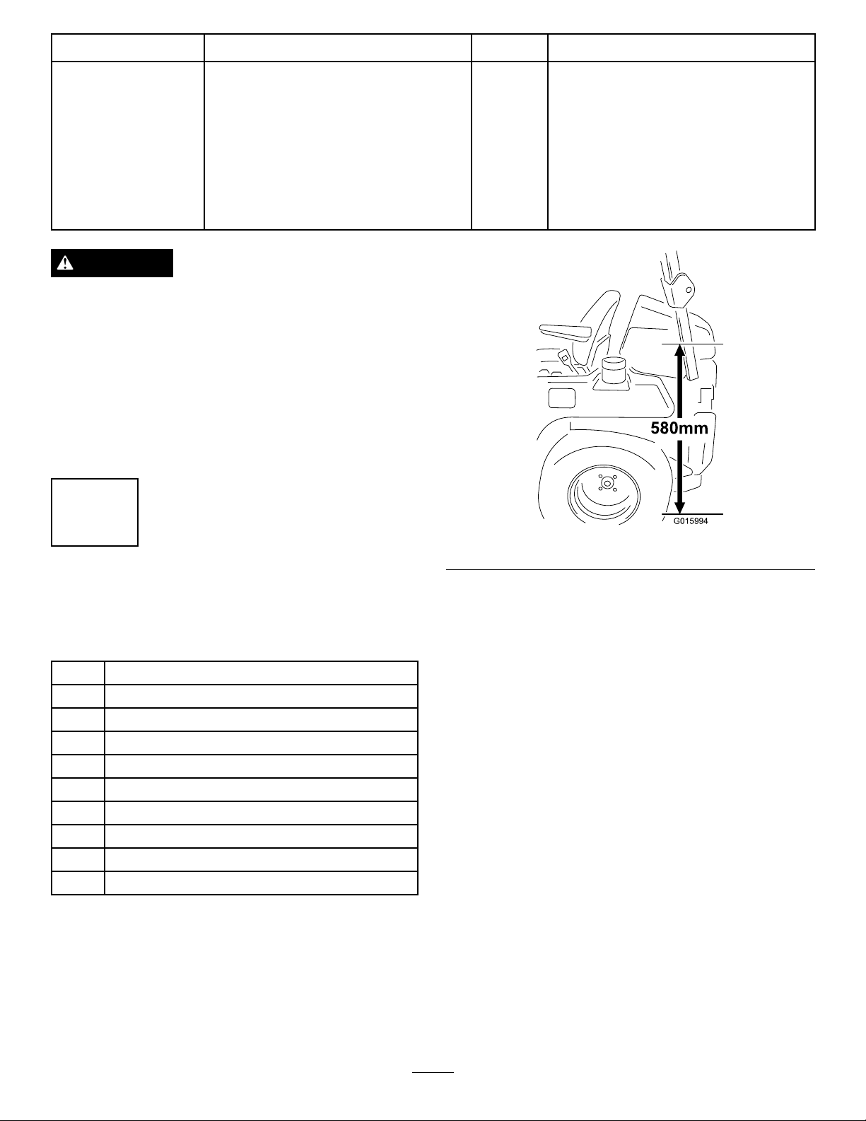
Figure1
2.Lifttheenginecover.
3.Alignthebottomofthebracketalongthemarkon
theROPS.SecurethebrackettotheROPSusing2
bolts(M8x75),2washers(M8),2washers(5/16
inch),and2nuts(M8)(Figure2).
1.Measure580mm(23inches)fromthegroundtothe
ROPSandmarkboththeleftandrighthandside
(Figure1).
2
Page 3
G016005
1
2
3
4
5
4
6
7
8
9
10
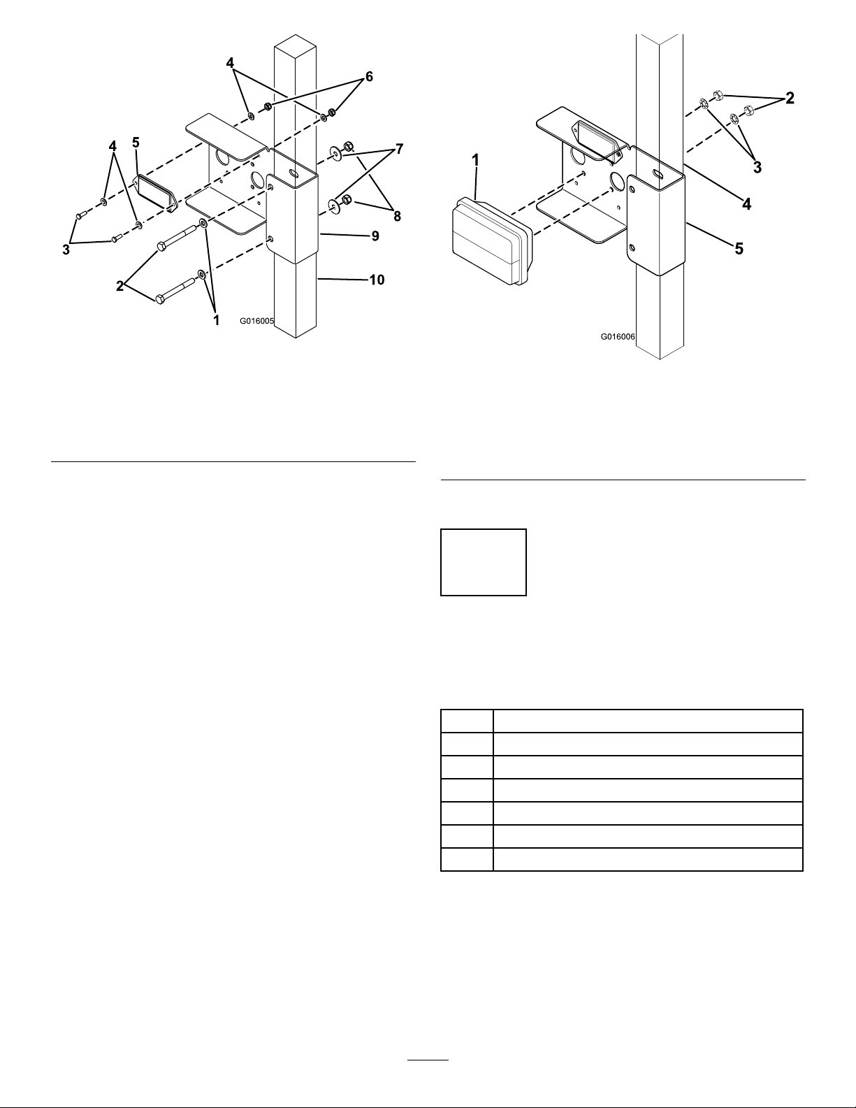
Figure2
G016006
1
2
3
4
5
1.Washers(M8)5.Reector
2.Bolts(M8x75)6.Nuts(M5)10.ROPS
3.Bolts(M5x16)7.Washers(5/16
inch)
4.Washers(M5)8.Nuts(M8)
9.Bracket
4.Mountthereectortothebracketusing2bolts(M5
x16),4washers(M5),and2nuts(M5)(Figure2).
5.Mounttherearlamptothebracketusing2starx
washersand2nutsincludedwiththelampassembly
Figure3).
(
Figure3
1.Rearlamp
2.Nut(includedwithrear
lamp)
3.Starxwasher(included
withrearlamp)
4.ROPS
5.Bracket
6.Repeatsteps2-5fortheoppositeside.
2
MountingtheHeadLampsand
Horn
Partsneededforthisprocedure:
1
Lefthandheadlamp
1Righthandheadlamp
2Frontlightbracket
1
Bolt(M8x20)
2
Washer(M8)
1
Nut(M8)
1Horn
Procedure
1.Locatethetwoboltsalongtheleftsiderailand
removethe2boltsand2nuts(Figure4).
3
Page 4
G015996
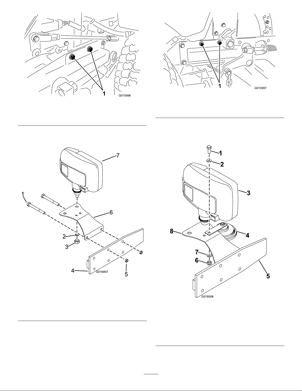
Figure4
1
2
3
4
5
6
7
G016007
G015997
3
4
5
6
2
1
7
8
G016008
Leftsiderail
1.Removethesenutsandbolts.
2.Mountafrontlightbrackettotheleftsiderailusing
theremovednutsandbolts(Figure5).
Figure6
Rightsiderail
1.Removethesenutsandbolts.
5.Mountthehorntotheleftsidebracketasshownin
Figure7.Secureitwithabolt(M8x20),2washers
(M8),andanut(M8).
Figure5
1.Bolt(existing)4.Siderail
2.Springwasher(included
withheadlamp)
3.Nut(includedwithhead
lamp)
3.Fixthelefthandheadlamptothefrontlightbracket
usingaspringwasherandanutprovidedwiththe
lamp(
4.Repeatsteps1-3fortherighthandside(Figure6).
Figure5).
5.Nut(existing)
6.Frontlightbracket
Figure7
Leftsidehornmount
1.Bolt(M8x20)5.Leftsiderail
2.Washer(M8)6.Nut(M8)
3.Leftheadlamp7.Washer(M8)
4.Horn8.Bracket
4
Page 5

G015998
1
Note:Allburrsmustberemovedfromtheedgesto
3
4
2
1
G016009
avoiddamagetothewires.
3
InstallingtheSwitches
Partsneededforthisprocedure:
2Blankswitch
1
Switchpanel
1
Combinationswitchassembly
1Adaptorswitchmount
1Hazardswitch
1Lightingswitch
1Hazardswitchlens
1Lightingswitchlens
2
Grommet
1
Cabletie
1
Bolt(M5)
1
Washer(M5)
1
Nut(M5)
1
Screw
1
Crimpterminal—Piggyback
1
Crimpterminal—Malebullet
1
Crimpterminal—Femalebullet
2.Connectthecombinationswitchassemblytothe
adaptorswitchmountandsecureitwithascrew
Figure9).
(
Figure9
Procedure
1.Cut40mm(1-1/2inch)offtherightmotioncontrol
Figure8).Useatwopartepoxyresintoglue
lever(
theadaptorswitchmountintothemotioncontrol
lever(Figure8).
1.Motioncontrollever
2.Adaptorswitchmount
3.Screw(includedwith
switchassembly)
4.Combinationswitch
assembly
3.Pushthehazardswitch,lightingswitch,and2blank
switchesintotheswitchpanelasshown(Figure10).
Figure8
1.40mm
5
Page 6

3
4
5
6
2
1
G016010
Figure10
G015999
G016000
3
4
!
1
2
G015942
1.Lightingswitch
lens
2.Hazardswitch
lens
3.Blankswitches5.Hazardswitch
4.Switchpanel
6.Lightingswitch
4.Installthehazardswitchlensandthelightingswitch
lens.
5.Fitthegrommetstotherearheadlampwiresby
feedingtheconnectorsthroughthegrommethole
oneatatime(
Figure11).
Figure12
1.Switches
2.Flashingrelaybase
3.Flasherrelay
4.Cabletie
7.Removethe4screwsonthecontrolpanel
(Figure13).
Figure13
1.Ignitionswitch
2.Screw
8.Iftheignitionswitchhas6terminals(Figure14),
proceedtostep9.Iftheignitionswitchhas5
terminals(Figure15),proceedtostep10.
1.Grommets
Figure11
6.Plugthewiringharnessintotheswitches.Securethe
ashingrelaybasewithabolt(M5),washer(M5),
andnut(M5).Cabletietheharnessasshown,and
plugintheasherrelay(Figure12).
6
Page 7

1
2
3
G015940
Figure14
1
2
3
4
5
G016442
G016001
1.Existingconnector3.Piggybackterminal
2.Redwire
Figure15
1.Thickpinkwire4.Malebullet
2.Thinpinkwire5.Redwire
3.Femalebulletconnector
Figure16
1.Screws
9.Crimpapiggybackconnectortotheredwireonthe
lightingharness.removethesingleconnectorfrom
theignitionswitch.Connectthepiggybacktothis
position,thenreconnecttheremovedconnectorto
thepiggyback(
Figure14).
10.Cutthethinpinkwirehalfwayup,striptheinsulation,
andconnectittothebluefemalebulletcrimp
terminal.Thencrimpthemalebullettotheredwire
onthelightingharnessandconnectittotheignition
switchinthepositionindicatedbyFigure15.
11.Retthecontrolpanel,thenttheswitchpanelto
therightsideofthecontrolpanelusing2existing
screws(
Figure16).
7
Page 8

4
G016012
1
2
3
4
5
6
RoutingtheWiringHarness
Partsneededforthisprocedure:
1Numberplatelampassembly
2
Bolt(M5x16)
4
Washer(1/4x3/4inch)
4
Nut(M5)
1Lampplatebracket
2
Bolt(M6x16)
4
Washer(M6x12)
2
Nut(M6)
1
30ampfuse
Procedure
1.Connectthe4wayand3wayconnectorstothe
combinationswitchassemblyandtheremaining
connectortotherighthandfrontheadlamp.Route
theharnesstotheleftalongthefrontrailand
connectthelefthandfrontheadlamp(
2.Routetheharnessalongtheleftsiderailtoconnect
thelefthandfrontheadlampandhorn.Connect
thetwosmallconnectorstothehornandthelarge
connectortothefrontheadlamp(Figure18).
3.Routetheharnesstotherearofthemachineto
connecttherearheadlampsandnumberplatelamp.
Feedthewirethroughtheleftrearbrackethole.
Bendtherearheadlampplatetabtoaangleof90
degreeupwards,thenconnectthewires.Repeatthe
sameprocessfortherightrearheadlamp(
Figure18).
Figure18).
Figure17
Z593only
1.Nuts(M5)4.Washer(M6x12)
2.Washer(1/4x3/4inch)5.Nuts(M6)
3.Bolts(M6x16)
6.Bracket
5.Z597only–Replacetheyellow20ampfusewith
ablue30ampfuse.
6.Cabletietheharnesstotheframe,ensuringthatitis
keptawayfromanyheatormovingparts(
Figure18).
7.Connecttheredandblackwireringterminalstothe
battery(Figure18).
8.Replaceandsecureallcovers.
4.Z597–Feedthewirethroughtherearpanel(center
slot)andthenumberplatelampgrommet.Connect
theconnectorstotheplate.Securetherearlamp
backingtotherearpanelwithabolt(M5x16),
2washers(1/4x3/4inch),and2nuts(M5)
(Figure18).
Z593–Feedthewirethroughtherearpanel(center
slot)andthenumberplatelampgrommet.Connect
theconnectorstotheplate.Mountthenumberplate
lamptothelampplatebracketusing2nuts(M5)and
2washers(1/4x3/4inch).Mounttheassemblyto
therearpanelusing2bolts(M6x16),4washers(M6
x12),and2nuts(M6)(Figure17).
8
Page 9

G01601 1
1
1.ForZ597only
Figure18
9
Page 10

Operation
1
2
G016073
1
2
G016074
SwitchFunctions
•Hazardwarningswitch—Operatesthehazard
warninglights,andwillworkwhethertheignition
isswitchedonoroff(Figure19).
–Pressthesideoftherockerswitchwiththe
hazardwarningsymboltoturnonthehazard
warninglights.
–Presstheothersideoftherockerswitchtoturn
offthehazardwarninglights.
Figure20
1.Headlampanddipped
beamswitch
2.Directionindicatorswitch
•Headlampanddippedbeamheadlampswitch—
Operatestheheadlampsonlywhentheignitionis
switchedon(Figure20).
–Pushthesliderforwardtoturnonthehead
lamp.
Figure19
1.Masterlightswitch2.Hazardwarningswitch
–Pushthesliderbackwardtoturnonthedipped
beamheadlamp.
•Hornswitch—Operatesthehornonlywhenthe
•Masterlightswitch—Operatesthefront,rear,and
headlamps.Onlyworksiftheignitionisswitched
on(Figure19).
ignitionisswitchedon.
–Pushthebuttontosoundthehorn.
–Releasethebuttontostopthehorn.
–Pressthesideoftherockerswitchwiththe
masterlightsymboltoturnonthelights.
–Presstheothersideoftherockerswitchtoturn
offthelights.
•Directionindicatorswitch—Operatestherightandleft-handdirectionindicatorlights.Onlywork
iftheignitionisswitchedon(
Figure20).
–Presstheleft-handsideoftheswitchtoggleto
turnontheleft-handdirectionindicatorlights.
–Presstheright-handsideoftheswitchtoggle
tothecentral(off)positiontoturnoffthe
left-handdirectionindicatorlights.
–Presstheright-handsideoftheswitchtoggleto
turnontheright-handdirectionindicatorlights.
–Presstheleft-handsideoftheswitchtoggle
tothecentral(off)positiontoturnoffthe
right-handdirectionindicatorlights.
10
Page 11

Maintenance
MaintenanceTips
•Checkthatalllightsareworkingonaregularbasis.
•Cleanalllensesregularlywithanonpetroleum-based
cleaner.
•Ensurethatthedrainslotsarekeptclearofdebris.
•Ifthemowerisgoingtobestoredoutdoors,verify
thatthelensissecuredproperlytopreventwater
fromenteringthelights.
Headlights—replacingabulb:
1.Removethelenscover.
2.Replacethebulb.
3.Replacethelenscover.
4.Adjustthelightstoensuretheycomplywithlocal
roadlegislation.
11
Page 12

TheToroTotalCoverageGuarantee
ALimitedWarranty
ConditionsandProductsCovered
TheT oro
toanagreementbetweenthem,jointlywarrantyourToroCommercial
product(“Product”)tobefreefromdefectsinmaterialsorworkmanship
fortwoyearsor1500operationalhours*,whicheveroccursrst.This
warrantyisapplicabletoallproductswiththeexceptionofAerators
(refertoseparatewarrantystatementsfortheseproducts).Wherea
warrantableconditionexists,wewillrepairtheProductatnocosttoyou
includingdiagnostics,labor ,parts,andtransportation.Thiswarranty
beginsonthedatetheProductisdeliveredtotheoriginalretailpurchaser.
*Productequippedwithanhourmeter.
®
Companyanditsafliate,T oroWarrantyCompany ,pursuant
InstructionsforObtainingWarrantyService
YouareresponsiblefornotifyingtheCommercialProductsDistributoror
AuthorizedCommercialProductsDealerfromwhomyoupurchasedthe
Productassoonasyoubelieveawarrantableconditionexists.Ifyouneed
helplocatingaCommercialProductsDistributororAuthorizedDealer ,or
ifyouhavequestionsregardingyourwarrantyrightsorresponsibilities,
youmaycontactusat:
CommercialProductsServiceDepartment
themanufacturerWarrantyCompany
811 1LyndaleAvenueSouth
Bloomington,MN55420-1 196
E-mail:commercial.warranty@toro.com
OwnerResponsibilities
AstheProductowner ,youareresponsibleforrequiredmaintenance
andadjustmentsstatedinyourOperator’sManual.Failuretoperform
requiredmaintenanceandadjustmentscanbegroundsfordisallowinga
warrantyclaim.
ItemsandConditionsNotCovered
Notallproductfailuresormalfunctionsthatoccurduringthewarranty
periodaredefectsinmaterialsorworkmanship.Thiswarrantydoesnot
coverthefollowing:
•Productfailureswhichresultfromtheuseofnon-T ororeplacement
parts,orfrominstallationanduseofadd-on,ormodiednon-T oro
brandedaccessoriesandproducts.Aseparatewarrantymaybe
providedbythemanufactureroftheseitems.
•Productfailureswhichresultfromfailuretoperformrecommended
maintenanceand/oradjustments.Failuretoproperlymaintainyour
ToroproductpertheRecommendedMaintenancelistedinthe
Operator’sManualcanresultinclaimsforwarrantybeingdenied.
•ProductfailureswhichresultfromoperatingtheProductinan
abusive,negligentorrecklessmanner.
•Partssubjecttoconsumptionthroughuseunlessfoundtobe
defective.Examplesofpartswhichareconsumed,orusedup,during
normalProductoperationinclude,butarenotlimitedto,brakes
padsandlinings,clutchlinings,blades,reels,bedknives,tines,
sparkplugs,castorwheels,tires,lters,belts,andcertainsprayer
componentssuchasdiaphragms,nozzles,andcheckvalves,etc.
•Failurescausedbyoutsideinuence.Itemsconsideredtobeoutside
inuenceinclude,butarenotlimitedto,weather,storagepractices,
contamination,useofunapprovedcoolants,lubricants,additives,
fertilizers,water,orchemicals,etc.
•Normalnoise,vibration,wearandtear,anddeterioration.
•Normal“wearandtear”includes,butisnotlimitedto,damageto
seatsduetowearorabrasion,wornpaintedsurfaces,scratched
decalsorwindows,etc.
Parts
Partsscheduledforreplacementasrequiredmaintenancearewarranted
fortheperiodoftimeuptothescheduledreplacementtimeforthatpart.
Partsreplacedunderthiswarrantyarecoveredforthedurationofthe
originalproductwarrantyandbecomethepropertyofT oro.Torowill
makethenaldecisionwhethertorepairanyexistingpartorassemblyor
replaceit.T oromayuseremanufacturedpartsforwarrantyrepairs.
NoteRegardingDeepCycleBatteryWarranty:
Deepcyclebatterieshaveaspeciedtotalnumberofkilowatt-hoursthey
candeliverduringtheirlifetime.Operating,recharging,andmaintenance
techniquescanextendorreducetotalbatterylife.Asthebatteriesinthis
productareconsumed,theamountofusefulworkbetweencharging
intervalswillslowlydecreaseuntilthebatteryiscompletelywornout.
Replacementofwornoutbatteries,duetonormalconsumption,isthe
responsibilityoftheproductowner.Batteryreplacementmayberequired
duringthenormalproductwarrantyperiodatowner’sexpense.
MaintenanceisatOwner’sExpense
Enginetune-up,lubricationcleaningandpolishing,replacementof
ItemsandConditionsNotCoveredlters,coolant,andcompleting
RecommendedMaintenancearesomeofthenormalservicesT oro
productsrequirethatareattheowner’sexpense.
GeneralConditions
RepairbyanAuthorizedT oroDistributororDealerisyoursoleremedy
underthiswarranty .
NeitherTheToroCompanynorToroWarrantyCompanyisliablefor
indirect,incidentalorconsequentialdamagesinconnectionwiththe
useoftheToroProductscoveredbythiswarranty,includingany
costorexpenseofprovidingsubstituteequipmentorserviceduring
reasonableperiodsofmalfunctionornon-usependingcompletion
ofrepairsunderthiswarranty.ExceptfortheEmissionswarranty
referencedbelow,ifapplicable,thereisnootherexpresswarranty.
Allimpliedwarrantiesofmerchantabilityandtnessforusearelimitedto
thedurationofthisexpresswarranty.Somestatesdonotallowexclusions
ofincidentalorconsequentialdamages,orlimitationsonhowlongan
impliedwarrantylasts,sotheaboveexclusionsandlimitationsmaynot
applytoyou.
Thiswarrantygivesyouspeciclegalrights,andyoumayalsohaveother
rightswhichvaryfromstatetostate.
CountriesOtherthantheUnitedStatesorCanada
CustomersshouldcontacttheirthemanufacturerDistributor(Dealer)toobtainguaranteepoliciesforyourcountry,province,orstate.Ifforanyreason
youaredissatisedwithyourDistributor’sserviceorhavedifcultyobtainingguaranteeinformation,contactthethemanufacturerimporter.Ifallother
remediesfail,youmaycontactusatthemanufacturerWarrantyCompany.
374-0277RevA
 Loading...