

Toro 26634 Parts Catalogue

Form No. 3327–200
53cm Rear Bagger Lawnmower
Model No. 26634–210000001 and Up
Parts Catalog
Ordering Replacement Parts
To order replacement parts, please supply: the part
number, the quantity, and the description of each
part desired.
Understanding Reference Numbers
Each identified part in an illustration has a reference
number. The reference number for a part also appears in
the parts list, along with other information about the part.
This catalog uses two special reference number formats,
one to indicate parts in a service assembly and another
to indicate the quantity of a given part in an illustration.
Service Assembly Reference Numbers
Parts in service assemblies have reference numbers in
the form a:b.
the entire service assembly and the b represents a
sequential number unique to each part within the service
assembly.
The a represents the reference number of
The TORO Company — 2001
All Rights Reserved
For example, a wheel assembly might be identified by
reference number 6, the tire by 6:1, the valve by 6:2,
and the wheel by 6:3. When you order the assembly
identified by reference number 6, you receive all parts
identified by reference numbers 6:1, 6:2, and 6:3.
However, you may also order any part individually.
Reference numbers of this type appear in illustrations
and in part lists.
Reference Numbers Indicating Quantity
In an illustration, if a reference number indicates more
than one part, the reference number has the form nX y.
The n represents the quantity of the part, the X is the
multiplication symbol, and the y represents the reference
number.
For example, in an illustration, the reference number
2X 37 means that two of the parts identified by reference
number 37 are indicated.

3327–200
Contents
Description Page Description Page
Deck Assembly 3. . . . . . . . . . . . . . . . . . . . . . . . . . .
Engine and Belt Guide Assembly 4. . . . . . . . . . . .
Blade and Brake Assembly 5. . . . . . . . . . . . . . . . .
Handle Assembly 6. . . . . . . . . . . . . . . . . . . . . . . . . .
Bag Assembly 7. . . . . . . . . . . . . . . . . . . . . . . . . . . .
Rear Drive Assembly 8. . . . . . . . . . . . . . . . . . . . . .
Gear Case Assembly No. 62–6673 9. . . . . . . . . .
Control Assembly 10. . . . . . . . . . . . . . . . . . . . . . . . .
Cylinder Assembly 11. . . . . . . . . . . . . . . . . . . . . . . . .
Cylinder Head Assembly 12. . . . . . . . . . . . . . . . . . .
Crankshaft Assembly 13. . . . . . . . . . . . . . . . . . . . . .
Carburetor Assembly 14. . . . . . . . . . . . . . . . . . . . . .
Governor Assembly 15. . . . . . . . . . . . . . . . . . . . . . . .
Air Cleaner Assembly 16. . . . . . . . . . . . . . . . . . . . . .
Fuel Tank Assembly 17. . . . . . . . . . . . . . . . . . . . . . .
Blower Housing and Flywheel Assembly 18. . . . . .
Rewind Starter Assembly 19. . . . . . . . . . . . . . . . . . .
Gasket Assembly 20. . . . . . . . . . . . . . . . . . . . . . . . .
Accessories
Description Model / Part No. Description Model / Part No.
Dethatcher Kit 59131. . . . . . . . . . . . . . . . . . . . . . . . . . . . Leaf Shredder Kit 59180. . . . . . . . . . . . . . . . . . . . . . . . . .
Part Description Abbreviations
Part descriptions in this catalog may include the following abbreviations.
Abbreviation Meaning Abbreviation Meaning
AR as required. . . . . . . . . . . . . . . . .
ASM assembly. . . . . . . . . . . . . . . .
CARR carriage. . . . . . . . . . . . . .
DEG degrees. . . . . . . . . . . . . . . .
FH flat head. . . . . . . . . . . . . . . . .
GA gauge. . . . . . . . . . . . . . . . .
HF hex flange. . . . . . . . . . . . . . . . .
HH hex head. . . . . . . . . . . . . . . . .
HHF hex head flange. . . . . . . . . . . . . . . .
HLH hex lag head. . . . . . . . . . . . . . . .
HJ hex jam. . . . . . . . . . . . . . . . . .
HOC height-of-cut. . . . . . . . . . . . . . . .
HS hex socket. . . . . . . . . . . . . . . . .
HSBH hex socket button head. . . . . . . . . . . . . .
HSFH hex socket flat head. . . . . . . . . . . . . . .
HSH hex socket head. . . . . . . . . . . . . . . .
HWH hex washer head. . . . . . . . . . . . . . .
HWHTF hex washer head. . . . . . . . . . . . .
thread forming
HYD hydraulic. . . . . . . . . . . . . . . .
INC incorporated. . . . . . . . . . . . . . . . .
LH left hand. . . . . . . . . . . . . . . . .
NI nylon insert. . . . . . . . . . . . . . . . . .
PPH Phillips pan head. . . . . . . . . . . . . . . .
PTH Phillips truss head. . . . . . . . . . . . . . . .
PTO power take off. . . . . . . . . . . . . . . .
RH right hand. . . . . . . . . . . . . . . . .
SFH slotted fillister head. . . . . . . . . . . . . . . .
SHH slotted hex head. . . . . . . . . . . . . . . .
SQH square head. . . . . . . . . . . . . . . .
SHWH slotted hex washer head. . . . . . . . . . . . . .
SPH slotted pan head. . . . . . . . . . . . . . . .
SRH slotted round head. . . . . . . . . . . . . . . .
STD standard. . . . . . . . . . . . . . . .
TAP self tapping. . . . . . . . . . . . . . . .
TTH Torx truss head. . . . . . . . . . . . . . . .
WH wing head. . . . . . . . . . . . . . . . .
2
8
9
4
5
2
3
1
1:2
3327–200
12
11:1
14
15
16
17
11
18
38
20
29
28
25
24
15
21
22
22:1
23
8
19
33
32
31
Sheet No.:2
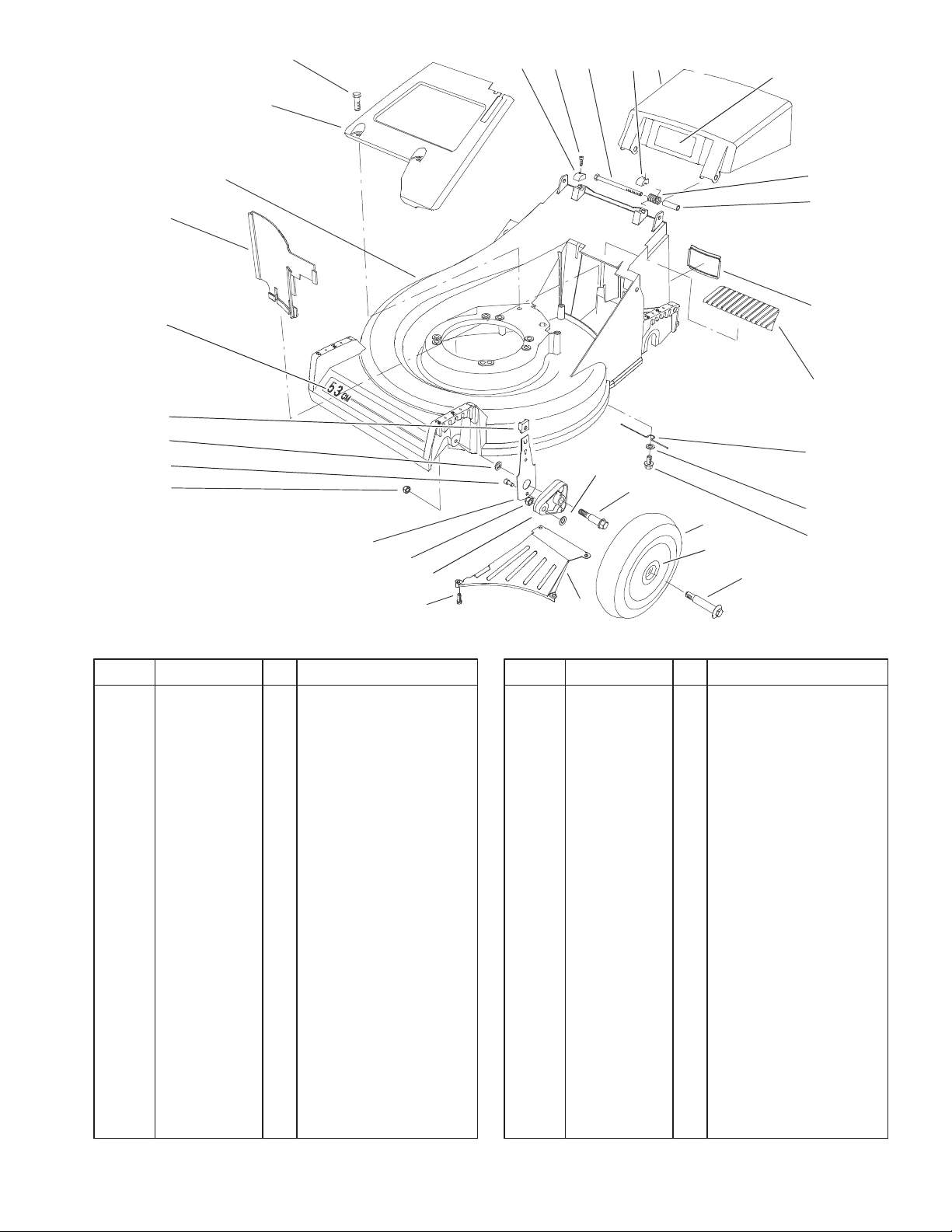
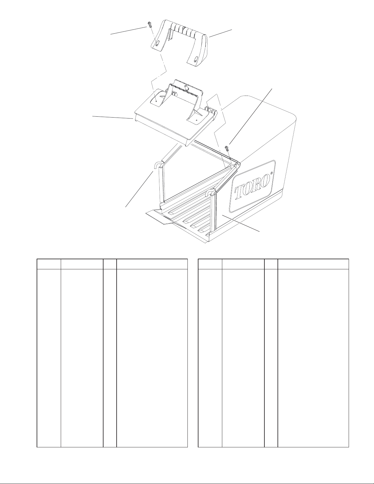
Deck Assembly
DescriptionPart No. Qty.Ref. No. DescriptionPart No. Qty.Ref. No.
1 17–1569 1 Door–Bag
1:2 93–4105 1 Decal–Danger
2 71–7900 1 Cap–Hinge Bolt, LH
3 322–29 2 Screw–HH
4 65–5210 2 Screw–Allen Hd
5 71–7910 1 Cap–Hinge Bolt, RH
8 32144–70 6 Screw–HH
9 65–5660–03 1 Panel–Screen
11 16–1769 1 Deck W/Decals
11:1 71–9870 1 Decal–Deck
12 66–0020 1 Panel–Vertical
14 25–7740 2 Knob–Arm
15 40–1940 4 Washer
16 32144–85 2 Screw–HH
17 3296–6 2 Nut–Lock, NI
18 66–0540 2 Front Spring Arm ASM
19 71–9640–03 1 Ramp–Discharge
20 66–0580 2 Arm–Pivot, Front
21 66–0560 2 Bolt–Shoulder
22 92–9592 2 Wheel ASM
22:1 27–6250 2 Bushing
23 92–1057 2 Bolt–Shoulder
24 71–9920 1 Cover–Top
25 71–9650 1 Cover–Access
28 71–8580 2 Spacer–Door
29 71–9840 2 Spring–Door
31 32144–15 1 Screw
32 3256–24 1 Washer–Flat
33 66–0620 1 Retainer–Belt
38 603773 2 Nut
3
3327–200
2
3
6
7
1
8
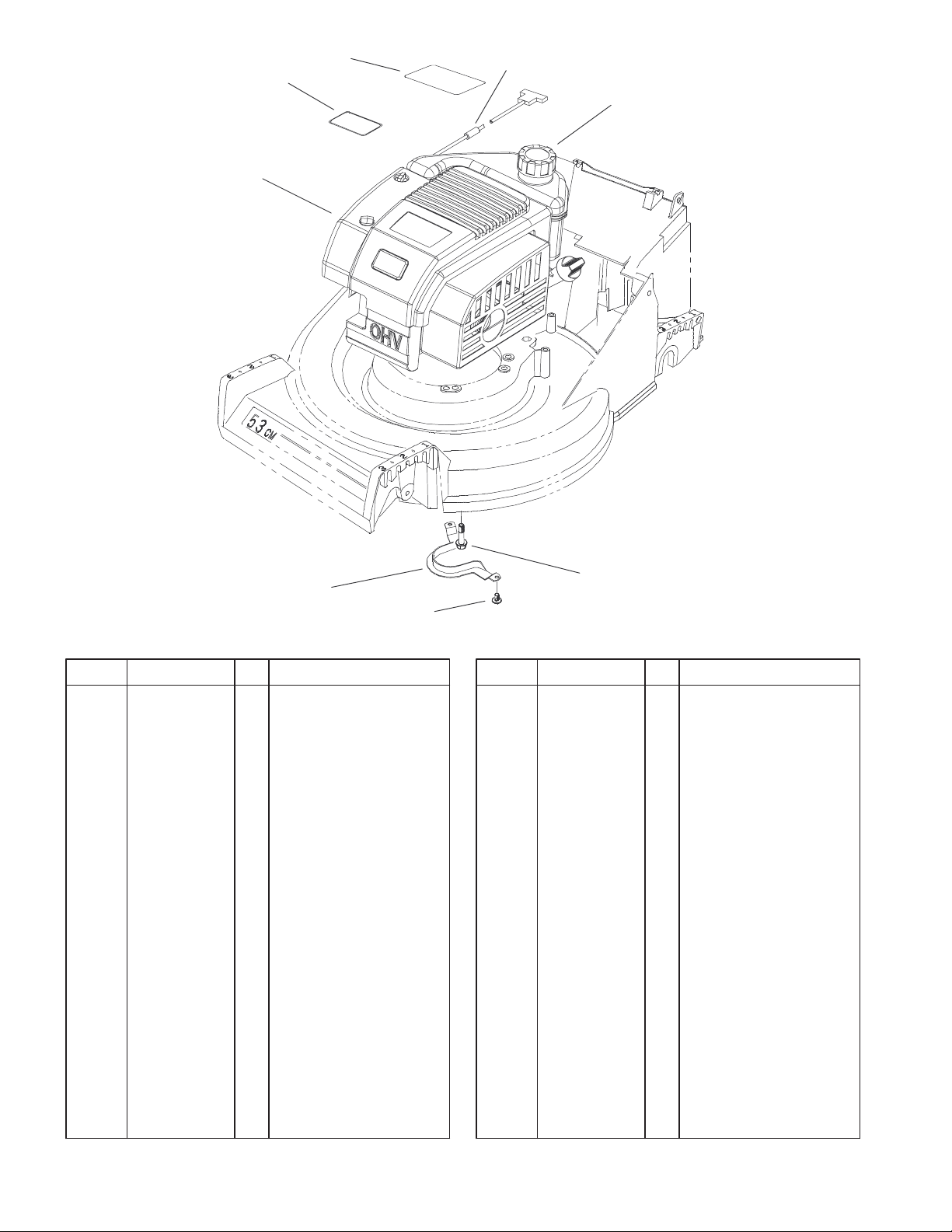
Engine and Belt Guide Assembly
DescriptionPart No. Qty.Ref. No. DescriptionPart No. Qty.Ref. No.
1 93–7198 1 Gas Cap ASM
2 98–2004 1 Decal–Engine
3 92–2289 1 Plate–Logo
6 1 Engine–Gts 200
7 2210–316 1 Stop–Rope
8 66–0570–03 1 Bracket–Guide, Belt
9 32144–102 3 Screw–HWH
10 32144–70 2 Screw–HH
9
Sheet No.:3
10
Not serviced separately
4
4
5
3327–200
2
1
9
3
1
6
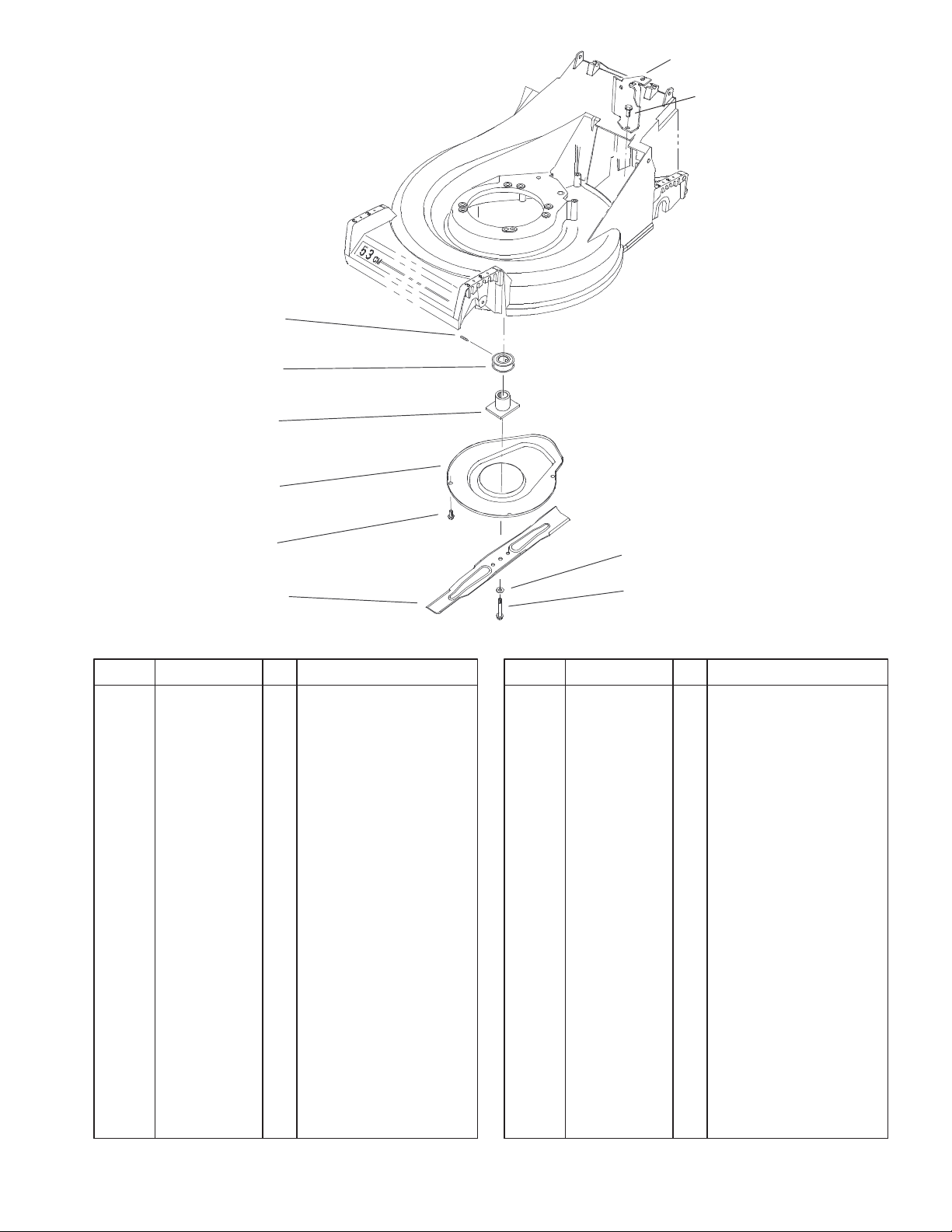
Blade and Brake Assembly
DescriptionPart No. Qty.Ref. No. DescriptionPart No. Qty.Ref. No.
1 32144–70 5 Screw–HH
2 66–0030–03 1 Bracket–Cable,
Support
3 95–1878 1 Pulley
4 99–5287 1 Blade Driver ASM
5 65–5200–03 1 Shield
6 42–1000–03 1 Blade
7 95–1748 1 Screw–Blade
8 3253–22 1 Washer–Lock
9 104–0214 1 Screw–Set
8
7
Sheet No.:4
5
3327–200
24
23
17
16
17:3
17:2
7
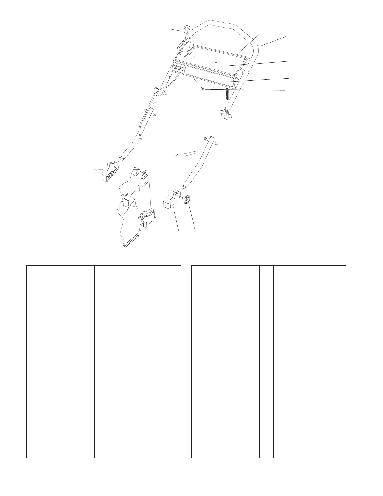
Handle Assembly
DescriptionPart No. Qty.Ref. No. DescriptionPart No. Qty.Ref. No.
1 71–8090 1 Handle–Mount, LH
2 19–4050 2 Knob
7 92–9665 5 Screw
16 94–4910 1 Handle–Dipped
17 104–7942 1 Panel–Service
17:2 71–9873 1 Decal–Panel Ohv
17:3 105–1339 1 Decal–Instruction
23 93–6632 1 Control–Ground
Speed
24 71–8100 1 Handle–Mount, RH
12
Sheet No.:5
6
3327–200
2
1
1
3
4
Bag Assembly
DescriptionPart No. Qty.Ref. No. DescriptionPart No. Qty.Ref. No.
1 32144–111 5 Screw–PPH
2 71–9480 1 Handle–Door
3 71–9470 1 Door–Bag
4 71–9930–03 1 Frame
5 71–9680 1 Grass Bag W/Pan
5
Sheet No.:6
7
3327–200
14
15
16
17
18
23
19
11
20
13
21
12
11
10
9
8
4
3
7
6
5
4
3
2
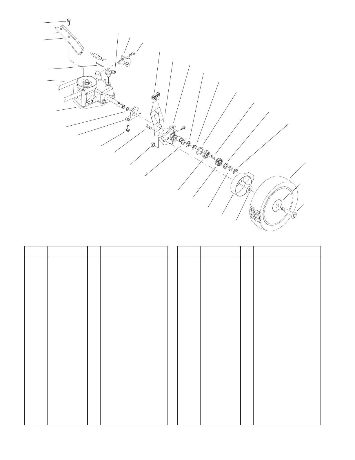
Rear Drive Assembly
DescriptionPart No. Qty.Ref. No. DescriptionPart No. Qty.Ref. No.
1 92–1057 2 Bolt–Shoulder
2 99–8136 2 Wheel And Gear ASM
2:1 1 Wheel ASM
2:1:1 27–6250 2 Bushing
3 65–2720 4 Ring–Klip
4 65–4740 4 Washer–Thrust,
Keyed
5 66–6050 1 Key–Rocking, LH
6 66–6040 1 Key–Rocking, RH
7 65–4710 2 Ring–Friction
8 65–5042 2 Pivot Arm ASM
9 65–5440 2 Spring Arm ASM
10 25–7740 2 Knob–Arm
11 32144–70 5 Screw–HH
12 76–2930 1 Retainer–Cable
13 76–0920 1 Lever–Shift
14 49–2040 2 Screw–Tapping
15 65–5190–03 1 Bracket–Guide, Belt
16 3272–5 1 Pin–Cotter
17 36–8070 1 V–Belt
18 62–6673 1 Gearcase ASM
19 66–0360 2 Cap–End
20 32144–85 2 Screw–HH
21 603773 2 Nut
22 65–4730 2 Washer–Arm, Pivot
23 237–153 2 O–Ring
22
24
25
26
27
28
Sheet No.:7
24 65–4760 2 Washer–Clutch
25 65–4750 2 Gear–Pinion
26 65–4720 2 Spring–Compression
27 74–1660 2 Cover–Wheel
28 74–1671 2 Spacer–Cover, Wheel
2:1:1
1
Not serviced separately
8
 Loading...