

Page 1
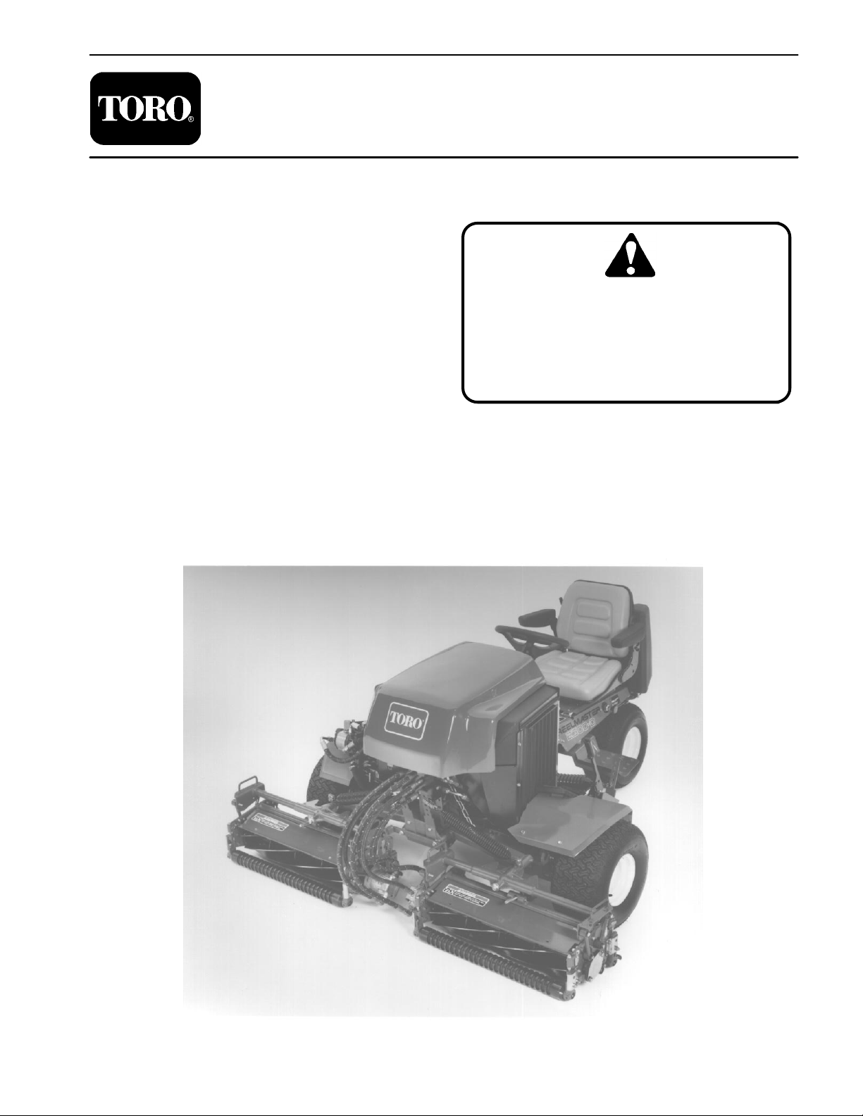
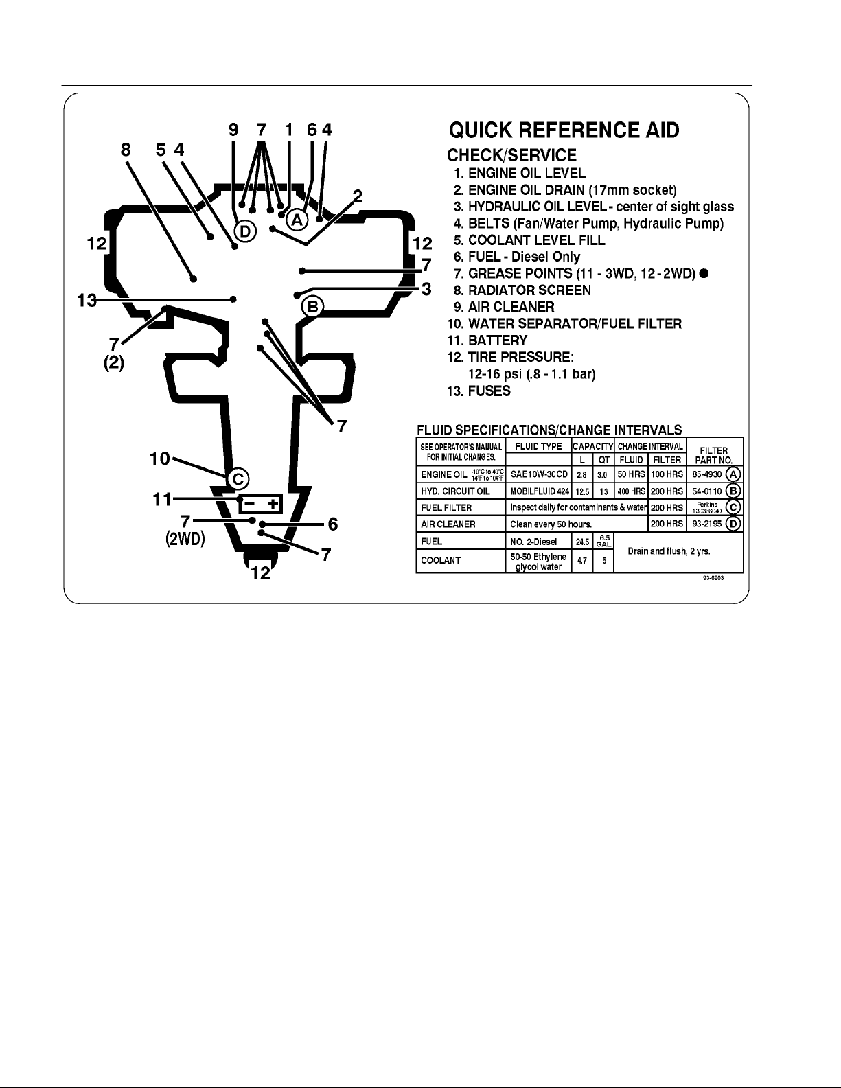
Reelmaster 2300–D/2600–D
Preface
The purpose of this publication is to provide the service
technician with information for troubleshooting, testing,
and repair of major systems and components on the
Reelmaster 2300–D/2600–D.
REFER TO THE TRACTION UNIT AND CUTTING
UNIT OPERATOR’S MANUALS FOR OPERATING,
MAINTENANCE AND ADJUSTMENT INSTRUCTIONS. Space is provided in Chapter 2 of this book to
insert the Operator’s Manuals and Parts Catalogs for
your machine. Replacement Operator’s Manuals are
available by sending complete Model and Serial Number to:
The Toro Company
8111 Lyndale Avenue South
Minneapolis, MN 55420
The T oro Company reserves the right to change product
specifications or this publication without notice.
Part No. 96876SL Rev. A
Service Manual
This safety symbol means DANGER, WARNING, or CAUTION, PERSONAL SAFETY
INSTRUCTION. When you see this symbol,
carefully read the instructions that follow.
Failure to obey the instructions may result in
personal injury.
NOTE: A NOTE will give general information about the
correct operation, maintenance, service, testing, or repair of the machine.
IMPORTANT: The IMPORTANT notice will give important instructions which must be followed to prevent damage to systems or components on the
machine.
The Toro Company – 1996, 1998
Page 2

This page is blank.
Page 3

Table Of Contents
Chapter 1 – Safety
Safety Instructions 1 – 1. . . . . . . . . . . . . . . . . . . . . . . . . .
Safety and Instruction Decals 1 – 4. . . . . . . . . . . . . . . .
Chapter 2 – Product Records and Manuals
Product Records 2 – 1. . . . . . . . . . . . . . . . . . . . . . . . . . .
Equivalents and Conversions 2 – 2. . . . . . . . . . . . . . . .
Torque Specifications 2 – 3. . . . . . . . . . . . . . . . . . . . . . .
Maintenance Interval Chart 2 – 4. . . . . . . . . . . . . . . . . .
Operation and Service History Report 2 – 5. . . . . . . . .
Chapter 3 – Engine
Introduction 3 – 2. . . . . . . . . . . . . . . . . . . . . . . . . . . . . . . .
Specifications 3 – 3. . . . . . . . . . . . . . . . . . . . . . . . . . . . . .
Special Tools 3 – 4. . . . . . . . . . . . . . . . . . . . . . . . . . . . . .
Adjustments 3 – 7. . . . . . . . . . . . . . . . . . . . . . . . . . . . . . .
Service and Repairs 3 – 9. . . . . . . . . . . . . . . . . . . . . . . .
Perkins 100 Series Workshop Manual
Chapter 4 – Hydraulic System
Specifications 4 – 2. . . . . . . . . . . . . . . . . . . . . . . . . . . . . .
General Information 4 – 3. . . . . . . . . . . . . . . . . . . . . . . .
Hydraulic Schematic 4 – 7. . . . . . . . . . . . . . . . . . . . . . . .
Hydraulic Flow Diagrams 4 – 8. . . . . . . . . . . . . . . . . . . .
Special Tools 4 – 16. . . . . . . . . . . . . . . . . . . . . . . . . . . . .
Troubleshooting 4 – 17. . . . . . . . . . . . . . . . . . . . . . . . . . .
Testing 4 – 19. . . . . . . . . . . . . . . . . . . . . . . . . . . . . . . . . . .
Adjustments 4 – 34. . . . . . . . . . . . . . . . . . . . . . . . . . . . . .
Service and Repairs 4 – 37. . . . . . . . . . . . . . . . . . . . . . .
Chapter 5 – Electrical System
Wiring Schematics 5 – 2. . . . . . . . . . . . . . . . . . . . . . . . .
Special Tools 5 – 9. . . . . . . . . . . . . . . . . . . . . . . . . . . . . .
Troubleshooting 5 – 10. . . . . . . . . . . . . . . . . . . . . . . . . . .
Electrical System Quick Checks 5 – 15. . . . . . . . . . . . .
Component Testing 5 – 17. . . . . . . . . . . . . . . . . . . . . . . .
Service and Repairs 5 – 27. . . . . . . . . . . . . . . . . . . . . . .
Chapter 6 – Wheels and Brakes
Specifications 6 – 2. . . . . . . . . . . . . . . . . . . . . . . . . . . . . .
Adjustments 6 – 3. . . . . . . . . . . . . . . . . . . . . . . . . . . . . . .
Service and Repairs 6 – 4. . . . . . . . . . . . . . . . . . . . . . . .
Chapter 7 – Cutting Units
Specifications 7 – 2. . . . . . . . . . . . . . . . . . . . . . . . . . . . . .
Special Tools 7 – 3. . . . . . . . . . . . . . . . . . . . . . . . . . . . . .
Trouble Shooting 7 – 5. . . . . . . . . . . . . . . . . . . . . . . . . . .
Adjustments 7 – 7. . . . . . . . . . . . . . . . . . . . . . . . . . . . . . .
Service and Repairs 7 – 11. . . . . . . . . . . . . . . . . . . . . . .
SafetyProduct Records
and Manuals
Engine
System
Hydraulic
Reelmaster 2300–D/2600–D
System
Electrical
Brakes
Wheels andCutting Units
Page 4

This page is blank.
Page 5
Table of Contents
SAFETY INSTRUCTIONS 1. . . . . . . . . . . . . . . . . . . . . .
Before Operating 1. . . . . . . . . . . . . . . . . . . . . . . . . . . .
While Operating 2. . . . . . . . . . . . . . . . . . . . . . . . . . . .
Safety Instructions
The REELMASTER 2300–D/2600–D conforms to the
American National Standards Institute’s (ANSI) safety
standards for riding mowers when equipped with rear
ballast (see Operator’s Manual). Although hazard control and accident prevention are partially dependent
upon the design and configuration of the machine, these
factors are also dependent upon the awareness, concern, and proper training of the personnel involved in the
operation, transport, maintenance, and storage of the
machine. Improper use or maintenance of the machine
can result in injury or death.
Chapter 1
Safety
Safety
Maintenance and Service 3. . . . . . . . . . . . . . . . . . . .
SAFETY AND INSTRUCTION DECALS 4. . . . . . . . . .
WARNING
To reduce the potential for injury or death,
comply with the following safety instructions.
Before Operating
Improper use or maintenance by the operator or owner
of the machine can result in injury . Reduce the potential
for any injury by complying with the following safety instructions.
WARNING
The engine exhaust contains carbon
monoxide, which is an odorless and
deadly poison. Carbon monoxide is also
known to the state of California to cause
birth defects. Do not run engine indoors
or in an enclosed area.
1. Read and understand the contents of the traction
unit and cutting unit operator’s manuals before operating the machine. To get replacement manuals, send
complete model and serial number to:
The Toro Company
8111 Lyndale Avenue South
Minneapolis, Minnesota 55420–1196
Use the Model and Serial Number when referring to your
machine. If you have questions about this Service
Manual, please contact:
The Toro Company
Commercial Service Department
8111 Lyndale Avenue South
Minneapolis, Minnesota 55420–1196
2. Only trained operators, skilled in slope operation
and who have read the Operator’s Manual, should operate the machine. Never allow children to operate the
machine or adults to operate it without proper instructions.
3. IMPORTANT: Always use proper rear ballast as
specified in the operator’s manual (see Rear Ballast of
the Operator’s Manual).
4. Become familiar with the controls and know how to
stop the machine and engine quickly.
Reelmaster 2300–D/2600–D
Page 1 – 1
Safety
Page 6

5. Do not carry passengers on the machine. Keep everyone, especially children and pets, away from the areas of operation.
6. Keep all shields, safety devices and decals in place.
lf a shield, safety device or decal is damaged, malfunctioning or illegible, repair or replace it before operating
the machine.
9. Make sure the work area is clear of objects which
might be picked up and thrown by the reels.
10. Fill the fuel tank with diesel fuel before starting the
engine. Avoid spilling any fuel. Since fuel is highly flammable, handle it carefully.
A. Use an approved fuel container.
7. Always wear substantial shoes. Do not operate machine while wearing sandals, tennis shoes or sneakers.
Do not wear loose fitting clothing because it could get
caught in moving parts and possibly cause personal injury .
8. Wearing safety glasses, safety shoes, long pants
and a helmet is advisable and required by some Iocal ordinances and insurance regulations.
While Operating
1 1. Do not run the engine in a confined area without adequate ventilation. Exhaust fumes are hazardous and
could be deadly.
12. Sit on the seat when starting and operating the machine.
13. Check interlock switches daily for proper operation
(see Checking Interlock Switches of the Operator’s
Manual). Do not rely entirely on safety switches; shut off
engine before getting off the seat. If a switch fails, replace it before operating the machine. The interlock system is for your protection, so do not bypass it. Replace
all interlock switches every two years.
B. Do not remove the cap from the fuel tank when
engine is hot or running.
C. Do not smoke while handling diesel fuel.
D. Fill fuel tank outdoors and not over one inch from
the top of the tank, (bottom of the filler neck). Do not
overfill.
F. Stay alert for holes in terrain and other hidden
hazards. Use extreme care when operating close to
sand traps, ditches, creeks, steep hillsides or other
hazards.
G. Reduce speed when making sharp turns. Avoid
sudden stops and starts. Use reverse pedal for
braking. The cutting units must be lowered when
going down slopes for steering control.
H. Before backing up, look to the rear and assure
that no one is behind the machine. Watch out for
traffic when near or crossing roads. Always yield the
right of way.
14. When starting the engine:
A. Engage parking brake.
B. Be sure traction pedal is in neutral and reel drive
is in the disengage position.
C. After the engine starts, release parking brake
and keep foot off the traction pedal. The machine
must not move. If movement is evident, the neutral
control linkage is incorrectly adjusted: therefore,
shut engine off and adjust until the machine does
not move when the traction pedal is released (see
Adjusting Transmission for Neutral of the Operator’s Manual).
D. Hills over 15 degrees should be mowed up and
down, not side to side (see Slope Gauge of the Operator’s Manual).
E. Mowing hills may be dangerous. Hills over 20
degrees should not be mowed (see Slope Gauge of
the Operator’s Manual).
15. Keep hands, feet, and clothing away from moving
parts and the reel discharge area. Grass baskets, if so
equipped, must be in place during reel operation for
maximum safety.
16. This product may exceed noise levels of 85 dB(A)
at the operator position. Ear protectors are recommended for prolonged exposure to reduce the potential
of permanent hearing damage.
17. Raise the cutting units when driving from one work
area to another.
18. Do not touch engine, muffler, exhaust pipe, or hydraulic tank while engine is running or soon after it has
stopped. These areas could be hot enough to cause
burns.
19. If a cutting unit strikes a solid object or vibrates abnormally , stop cutting unit immediately . T urn the engine
off, wait for all motion to stop and inspect for damage.
A damaged or bedknife must be repaired or re-
placed before operation is continued.
Safety
Page 1 – 2
Reelmaster 2300–D/2600–D
Page 7

20. Before getting off the seat:
A. Move the traction pedal to neutral.
B. Set the parking brake.
C. Disengage the cutting units and wait for the reels
to stop spinning.
Maintenance and Service
22. Before servicing or making adjustments to the ma-
chine, stop the engine and remove the key from the
switch to prevent accidental starting of the engine.
23. When changing attachments, tires or performing
other service, use the correct blocks, hoists and jacks.
Always chock or block the wheels and use jack stands
or solid wood blocks to support the raised machine. If
the traction unit is not properly supported by blocks or
jack stands, the unit may move or fall resulting in personal injury.
D. Stop the engine and remove the key from the ignition switch.
21. Whenever the machine is left unattended, make
sure the reels are not spinning, the key is removed from
ignition switch, and the parking brake is set.
Safety
28. Before disconnecting or performing any work on the
hydraulic system, all pressure in system must be relieved by stopping the engine and lowering cutting units
to the ground.
29. If major repairs are ever needed or if assistance is
desired, contact an Authorized Toro Distributor.
30. Reduce potential fire hazards. Keep the engine
area free of excessive grease, grass, leaves, and accumulation of dirt.
24. Check performance of all interlock switches daily.
Do not defeat interlock system. It is for your protection.
25. Ensure the entire machine is in good operating
condition. Frequently check and keep all nuts, bolts,
screws, and hydraulic fittings tight.
26. Before applying pressure to the hydraulic system,
make sure all hydraulic line connectors are tight and all
hydraulic hoses and lines are in good condition .
27. Keep body and hands away from pin hole leaks or
nozzles that eject hydraulic fluid under high pressure.
Use paper or cardboard, not hands, to search for leaks.
Hydraulic fluid escaping under pressure can have sufficient force to penetrate the skin and cause serious injury. lf fluid is injected into the skin, it must be surgically
removed within a few hours by a doctor familiar with this
form of injury or gangrene may result.
31. If the engine must be running to perform a maintenance adjustment, keep hands, feet, clothing, and any
other parts of the body away from the cutting units and
any moving parts. Keep everyone away.
32. Do not overspeed the engine by changing governor
settings. T o assure safety and accuracy , have an Authorized Toro Distributor check maximum engine speed
with a tachometer.
33. The engine must be shut off before checking oil or
adding oil to the crankcase.
34. To insure optimum performance and safety, use
genuine TORO replacement parts and accessories. Replacement parts and accessories made by other manufacturers could be dangerous, and such use could void
the product warranty of The Toro Company.
Reelmaster 2300–D/2600–D
Page 1 – 3
Rev . A
Safety
Page 8
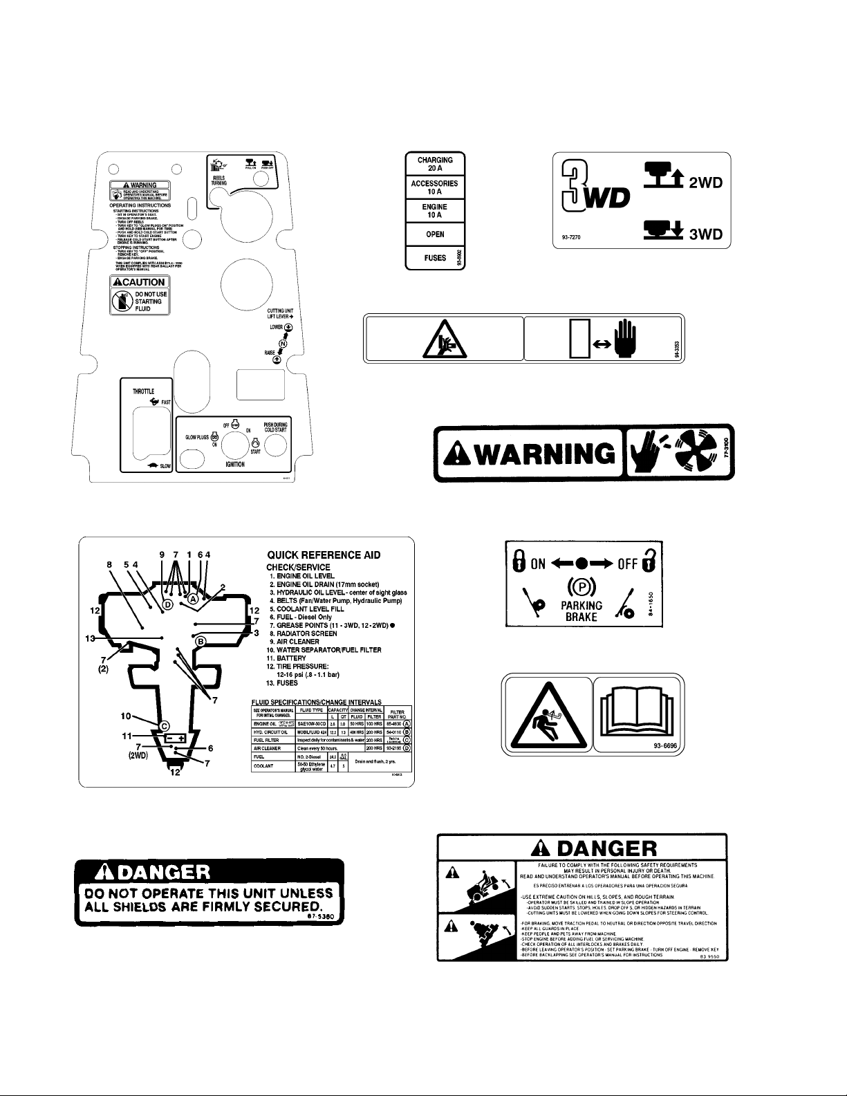
Safety and Instruction Decals
The following safety and instruction decals are affixed
to the traction unit. If any decal becomes illegible or
damaged, install a new decal. Part numbers are listed
UNDER CONTROL P ANEL
(Part No. 93–6902)
WARNING! Pinch Point between Carrier Frame and Cutting
ON INSTRUMENT P ANEL
(Part No. 94–4985)
below and in your Parts Catalog. Order replacements
from your Authorized Toro Distributor.
ON LEFT SIDE OF SEAT PANEL
(Part No. 92–7270)
Model 03427 only
ON CARRIER FRAME
(Part No. 94–3353)
Unit
ON FAN SHROUD
(Part No. 77–3100)
Rotating Parts
Safety
ON UNDER SEA T
(Part No. 93–6903)
ON INSIDE OF
FRONT RIGHT PANEL
(Part No. 67–5360)
Page 1 – 4
ON LEFT FENDER
(Part No. 84–1650)
ON LIFT ARMS
(Part No. 93–6696)
WARNING! Spring Loaded Mechanism,
Read Disassembly Procedure
ON SKIRT PANEL
(Part No. 83–9550)
Reelmaster 2300–D/2600–D
Page 9

&))!% # !## *) %( % )
"*()$%) '&*'(
') &
Safety
Reelmaster 2300–D/2600–D
Page 1 – 5
Safety
Page 10

Safety
Page 1 – 6
Reelmaster 2300–D/2600–D
Page 11

Table of Contents
Chapter 2
Product Records and Manuals
PRODUCT RECORDS 1. . . . . . . . . . . . . . . . . . . . . . . . .
EQUIVALENTS AND CONVERSIONS 2. . . . . . . . . . .
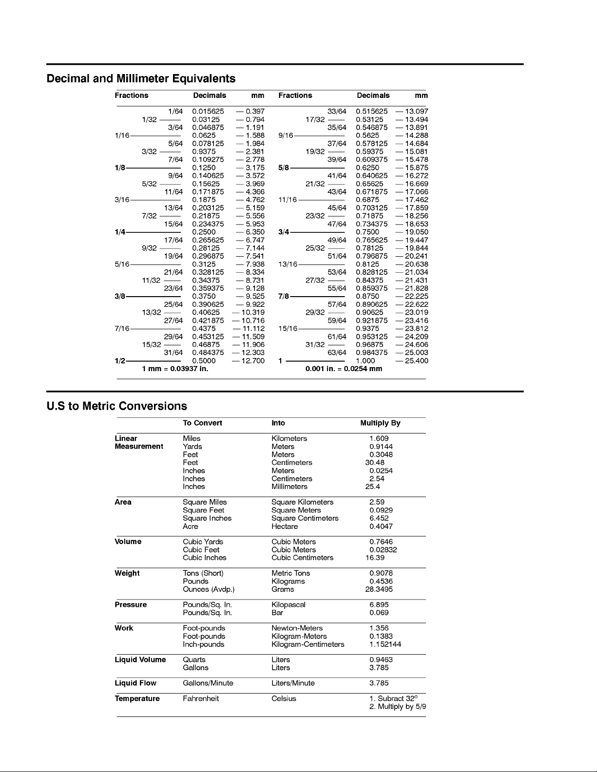
Decimal and Millimeter Equivalents 2. . . . . . . . . . . .
U.S. to Metric Conversions 2. . . . . . . . . . . . . . . . . . .
Product Records
Record information about your Reelmaster
2300–D/2600–D on the OPERATION AND SERVICE
HISTORY REPOR T form. Use this information when referring to your machine.
TORQUE SPECIFICATIONS 3. . . . . . . . . . . . . . . . . . .
Capscrew Markings and Torque Values – U.S. 3. .
Capscrew Markings and Torque Values – Metric 3
MAINTENANCE INTERV AL CHAR T 4. . . . . . . . . . . . .
OPERATION AND SERVICE HISTOR Y REPORT 5.
and Manuals
Product Records
Insert Operator’s Manuals and Parts Catalogs for your
Reelmaster 2300–D/2600–D at the end of this section.
Reelmaster 2300–D/2600–D
Page 2 – 1
Product Records and Manuals
Page 12
Equivalents and Conversions
Product Records and Manuals
Page 2 – 2
Reelmaster 2300–D/2600–D
Page 13
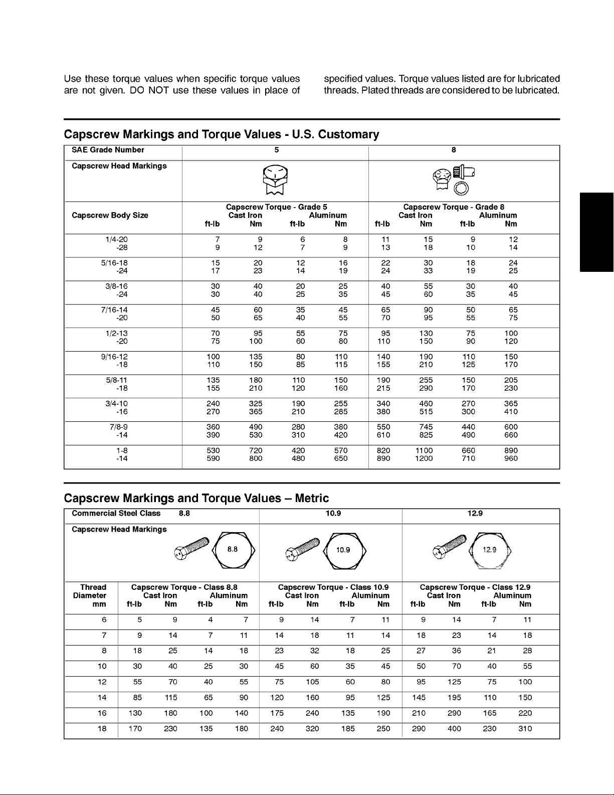
Torque Specifications
and Manuals
Product Records
Reelmaster 2300–D/2600–D
Page 2 – 3
Product Records and Manuals
Page 14
Maintenance Interval Chart
Product Records and Manuals
Page 2 – 4
Reelmaster 2300–D/2600–D
Page 15

EQUIPMENT OPERATION AND SERVICE HISTORY REPORT
for
REELMASTER 2300–D/2600–D
TORO Model and Serial Number: _____________–___________
Engine Numbers: _________________________
Transmission Numbers: _________________________
Date Purchased: _________________________ Warranty Expires___________
Purchased From: _________________________
_________________________
_________________________
Contacts: Parts _________________________ Phone___________________
and Manuals
Product Records
Service _________________________ Phone___________________
Sales _________________________ Phone___________________
See your TORO Distributor for other Publications, Manuals, and Videos from the TORO company.
Reelmaster 2300–D/2600–D
Page 2 – 5
Product Records and Manuals
Page 16
REELMASTERR 2300–D/2600–D Maintenance Schedule
Minimum Recommended Maintenance Intervals:
Maintenance Procedure
Inspect Air Filter, Dust Cup, and Baffle
Lubricate All Grease Fittings
{ Change Engine Oil
{ Check Fan and Alternator Belt Tensions
{ Change Engine Oil and Filter
{ Check Traction Belt Tension
Service Air Filter
Replace Fuel Filter/Water Separator
{ Replace Hydraulic Filter
{ Torque Wheel Lug Nuts
Replace Hydraulic Fluid
Check Battery Level/Connections
Inspect Traction Linkage Movement
* Inspect Spider Coupling for Wear
} Torque Head Bolts and Adjust Valves
} Check Engine RPM (idle and full throttle)
Every
50hrs
A–Level
Service
Maintenance Interval & Service
Every
100hrs
B–Level
Service
Every
200hrs
C–Level
Service
Every
400hrs
D–Level
Service
{ Initial break in at 10 hours
* Every 400 hours or annually, whichever occurs first
} Initial break in at 50 hours
Replace all Moving Hoses
Replace Safety Switches
Cooling System – Flush/Replace Fluid
Replace Thermostat
Fuel Tank – Drain/Flush
Hydraulic Tank – Drain/Flush
(See Operator’s and Service Manuals for specifications and procedures.)
Items listed are recommended every 1000 hours
Annual Recommendations:
or 2 years, whichever occurs first.
Product Records and Manuals
Page 2 – 6
Reelmaster 2300–D/2600–D
Page 17

REELMASTERR 2300–D/2600–D Daily Maintenance Check List
Daily Maintenance: (duplicate this page for routine use)
Daily Maintenance Check For Week Of ________________
Maintenance
Check Item b
n Safety Interlock Operation
n Brake Operation
n Engine Oil Level
n Cooling System Fluid Level
Drain Water/Fuel Separator
n Air Filter, Dust Cup, and Baffle
n Radiator & Screen for Debris
n Unusual Engine Noises
n Unusual Operating Noises
n Hydraulic System Oil Level
n Hydraulic Hoses for Damage
n Fluid Leaks
n Fuel Level
1
1
2
1
1
MON
________HRS
TUES
________HRS
WED
________HRS
Unit Designation: ____________
TORO ID #: ________–________
THURS
________HRS
FRI
________HRS
SAT
________HRS
SUN
________HRS
and Manuals
and Manuals
Product Records
Product Records
n Tire Pressure
n Instrument Operation
n Reel–to–Bedknife Adjustment
n Height–of–Cut Adjustment
Lubricate All Grease Fittings
3
Touch–up Damaged Paint
1
= Check proper section of Operator’s Manual for fluid specifications.
2
= Check glow plug and injector nozzles, if hard starting, excess smoke or rough running is noted.
3
= Accomplish immediately after every washing, regardless of the interval listed.
Notation for areas of concern: Inspection performed by:__________________
Item
Date Information
1
2
3
4
5
6
7
(See Operator’s and Service Manuals for specifications and procedures.)
Reelmaster 2300–D/2600–D
Page 2 – 7
Product Records and Manuals
Page 18
Date: ________________
Service Air Filter
Replace Fuel Filter/Water Separator
Replace Hydraulic Filter
Torque Wheel Lug Nuts
A and B – Sevice required
________________________________
________________________________
________________________________
________________________________
________________________________
________________________________
________________________________
________________________________
________________________________
________________________________
________________________________
________________________________
________________________________
Form No. 95–872–SL(See Operator’s and Service Manual for specifications and procedures.)
Remarks:
R
TORO I.D. #:
__________________–__________________
A B C D Other
Service to perform (circle):
REELMASTER 2300–D/2600–D Supervisor Maintenance Work Order
Unit Designation:
(Duplicate this page for routine use.)
Hours:
Technician:
Change Engine Oil Filter
Check Traction Belt Tension
A – Service required
_______________________________
_______________________________
_______________________________
_______________________________
_______________________________
Inspect Air Filter, Dust Cup, and Baffle
Lubricate All Grease Fittings
Change Engine Oil
Check Fan and Alternator Belt Tension
________________________________
________________________________
________________________________
A– Service (every 50 hours) B – Service (every 100 hours) C – Service (every 200 hours)
________________________________
_______________________________
________________________________
Replace Moving Hoses
Replace Safety Switches (Every 2 yrs)
Coolant System – Flush/Replace Fluid
Replace Thermostat
Fuel Tank – Drain/Flush
Hydraulic Tank – Drain/Flush
Replace Hydraulic Fluid
Check Battery Level/Connections
D – Service (every 400 hours) Other – Annual Service and Specials Additional Service Items
Inspect Traction Linkage Movement
Inspect Spider Coupling for Wear
Torque Head Bolts and Adjust Valves
Check Engine RPM (Idle & Full Throttle)
_______________________________
A, B, and C – Sevice required
_______________________________
_______________________________
________________________________
________________________________
Product Records and Manuals
Page 2 – 8
Reelmaster 2300–D/2600–D
Page 19

Table of Contents
Chapter 3
Engine
INTRODUCTION 2. . . . . . . . . . . . . . . . . . . . . . . . . . . . . .
SPECIFICA TIONS 3. . . . . . . . . . . . . . . . . . . . . . . . . . . .
SPECIAL TOOLS 4. . . . . . . . . . . . . . . . . . . . . . . . . . . . .
GENERAL INFORMATION 6. . . . . . . . . . . . . . . . . . . . .
Fuel Shutoff Valves 6. . . . . . . . . . . . . . . . . . . . . . . . . .
ADJUSTMENTS 7. . . . . . . . . . . . . . . . . . . . . . . . . . . . . .
Alternator Belt 7. . . . . . . . . . . . . . . . . . . . . . . . . . . . . .
Throttle Linkage 8. . . . . . . . . . . . . . . . . . . . . . . . . . . .
SERVICE AND REPAIRS 9. . . . . . . . . . . . . . . . . . . . . .
Bleeding the Fuel System 9. . . . . . . . . . . . . . . . . . . .
Air Cleaner 10. . . . . . . . . . . . . . . . . . . . . . . . . . . . . . . .
Cleaning the Radiator and Screen 11. . . . . . . . . . . . .
Changing the Engine Oil and Filter 12. . . . . . . . . . .
Checking the Cooling System 12. . . . . . . . . . . . . . . .
Engine Removal 13. . . . . . . . . . . . . . . . . . . . . . . . . . .
Engine Reinstallation 18. . . . . . . . . . . . . . . . . . . . . . .
PERKINS 100 SERIES WORKSHOP MANUAL
Engine
Reelmaster 2300–D/2600–D Page 3 – 1 Engine
Page 20

Introduction
This Chapter gives information about specifications,
maintenance, troubleshooting, testing, and repair of the
diesel engine used in the Reelmaster 2300–D/2600–D
mower.
Most repairs and adjustments require tools which are
commonly available in many service shops. Special
tools are described in the Special T ools section. The use
of some specialized test equipment is explained. How-
ever, the cost of the test equipment and the specialized
nature of some repairs may dictate that the work be
done at an engine repair facility.
Service and repair parts for Perkins engines are supplied through your local Perkins/Detroit Diesel dealer. If
no parts list is available, be sure to provide your dealer
or distributor with the Perkins model and serial number.
Engine
Page 3 – 2
Reelmaster 2300–D/2600–D
Page 21

Specifications
Item Description
Make / Designation Perkins, vertical in–line, 4–stroke, water–cooled Diesel,
103–07 KL 70275 & KL 70372
Combustion Chamber IDI special swirl–combustion type
Number of Cylinders 3
Bore x Stroke mm (in.) 67 x 64 (2.64 x 2.52)
Total Displacement cc (cu. in.) 676 (41.23)
Compression Ratio 24:1
Firing Order 1– 2–3
Dry Weight (approximate) kg (lb.) 64 (141)
Fuel Grade No. 2D diesel fuel (ASTM specification)
Fuel Injection Pump Bosch type plunger
Governor Mechanical
Idle Speed (no load) 1400 + 50 RPM
High Idle (no load) 3200 + 50 RPM
Engine
Fuel Injector Nozzle Bosch throttle type
Fuel Injection Working Pressure kg/cm2 (psi) 115 to 125 (1636 to 1778)
Injection Timing 28.5 to 30.5 B.T.D.C.
Engine Oil SAE 10W30 SF, CD
Oil Pump Gear driven trochoid type
Crankcase Oil Capacity liter (U.S. qt.) 2.8 (3.0) with filter
Water Pump Belt driven centrifugal type
Cooling System Capacity liter (U.S. qt.) 4.7 (5.0)
Starter 12 VDC 1.2 KW
Alternator/Regulator 12 VDC 14 AMP
Glow Plug Sheathed type
Reelmaster 2300–D/2600–D Page 3 – 3 Engine
Page 22
Special Tools
Order special tools from
APPLICATIONS GUIDE (Commercial Products
TORO SPECIAL TOOLS AND
).
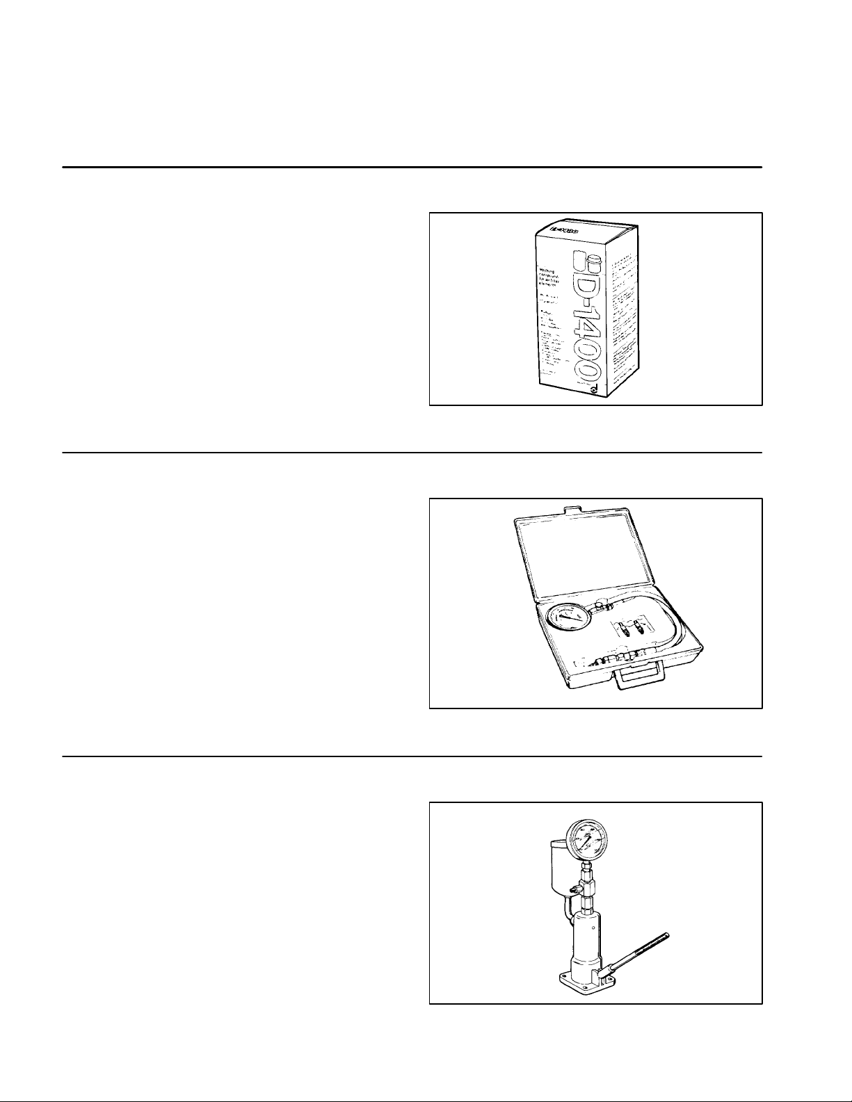
Filter Cleaner
Mix with water and use solution to wash the Donaldson
air cleaner element.
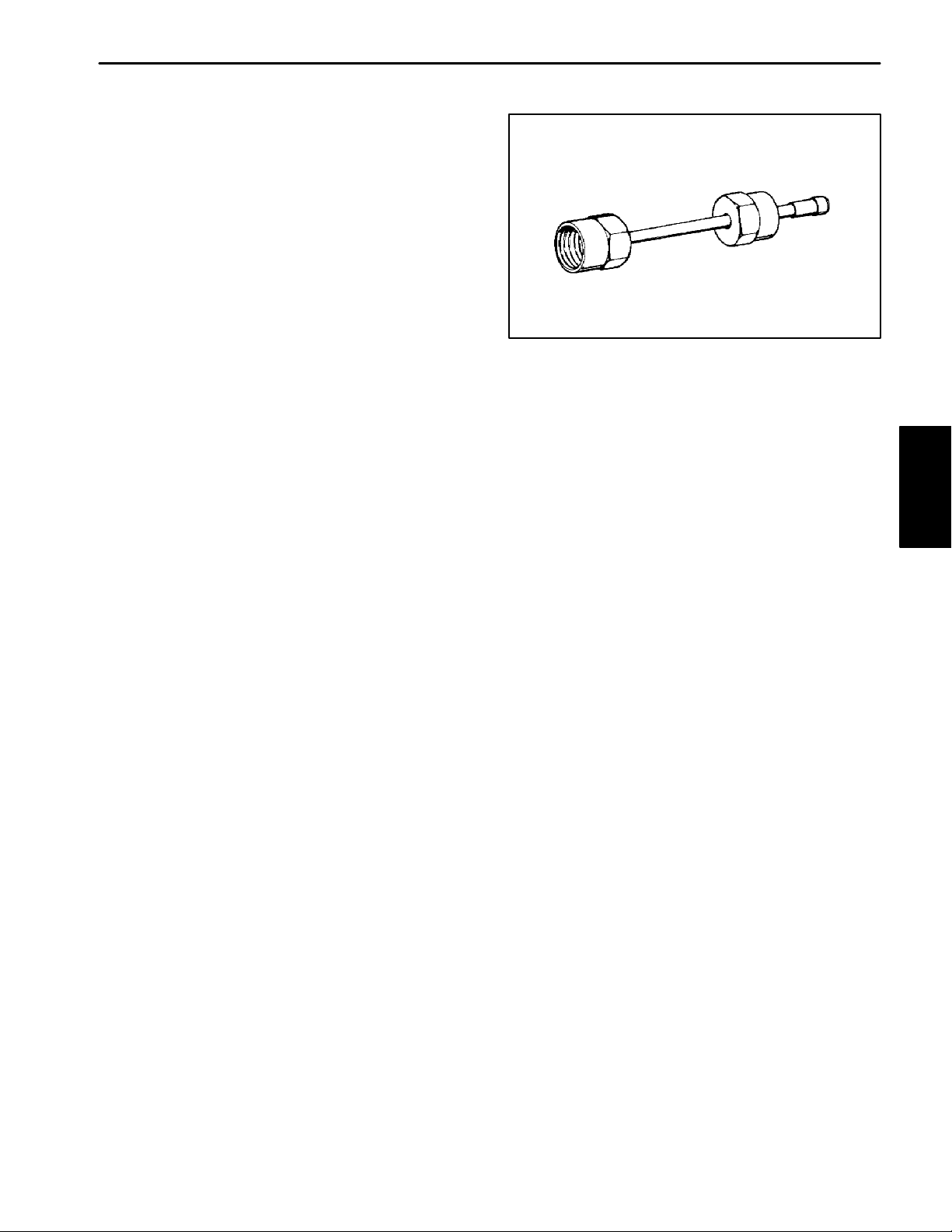
Diesel Engine Compression Test Kit
This 0 to 1000 PSI gauge allows testing of diesel engines for checking the general operating condition of the
engine. The kit includes a case, gauge with hose, glow
plug hole adapters, and instructions.
Some tools may be listed in the Reelmaster
2300–D/2600–D Parts Catalog. Tools may also be
available from a local supplier.
Figure 1
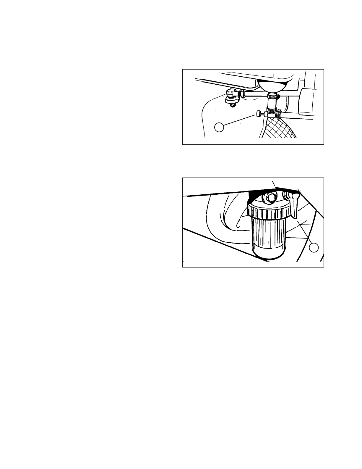
Nozzle Tester
This tests the condition and opening pressure of fuel injection nozzles.
Engine
Page 3 – 4
Figure 2
Figure 3
Reelmaster 2300–D/2600–D
Page 23
Nozzle Test Adapter
This adapter is required to test the fuel injection nozzles.
Figure 4
Engine
Reelmaster 2300–D/2600–D Page 3 – 5 Engine
Page 24
General Information
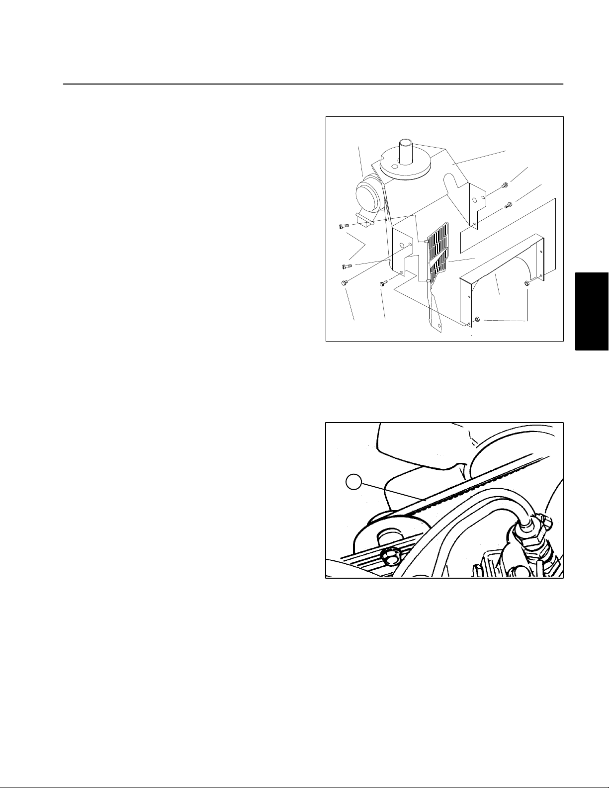
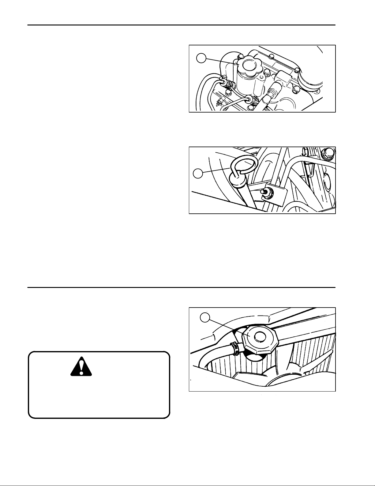
Fuel Shutoff Valves
These valves should be shut when removing the engine
or placing the unit in long term storage.
1
Figure 5
1. Fuel shut off (under the fuel tank)
Figure 6
1. Fuel shut off valve (on the fuel filter)
1
Engine
Page 3 – 6
Reelmaster 2300–D/2600–D
Page 25
Adjustments
Alternator Belt
1. Gain access to the alternator belt (Fig 7).
A. Loosen top hose clamp securing the upper por-
tion of the hose connected to the air cleaner (8).
B. Remove cap screws (1) and lock flange nuts (2).
Remove hex head screws (3).
C. On European models, remove hex head screws
(4) from the guard (5) and air cleaner housing (6).
D. Pull air cleaner housing from the radiator top
shroud (7) and hose. Plug air cleaner hose and hose
inlet to the air cleaner.
2. Loosen bolts securing alternator to the engine and
adjusting strap.
3. Adjust alternator belt to the proper tension. T ension
alternator belt so it deflects 0.20 inch with a 2 to 3 pound
load applied midway between the crankshaft and alternator pulleys (Fig. 8).
4. Tighten bolts securing the alternator to the engine.
5. Reinstall air cleaner housing (Fig 7).
A. Unplug air cleaner hose and hose inlet to the air
cleaner.
8
4
3
1. Cap screw
2. Lock flange nut
3. Hex head screw
4. Hex head screw
1
Figure 7
6
3
1
5
7
2
5. Guard (Europe)
6. Air cleaner housing
7. Radiator top shroud
8. Air cleaner
Engine
B. Place air cleaner housing (6) on the radiator top
shroud (7). Reconnect upper end of the air cleaner
hose to the air cleaner (8). Align holes to receive
fasteners.
C. On European models, reinstall hex head screws
(4) into guard (5) through the air cleaner housing (6).
D. Secure cap screws (1) and lock flange nuts (2) to
air cleaner housing and radiator top shroud (7).
E. Secure hex head screws (3) into the air cleaner
housing and radiator assembly.
F . Tighten hose clamp securing the hose to the air
cleaner.
1
Figure 8
1. Engine belt
Reelmaster 2300–D/2600–D Page 3 – 7 Engine
Page 26
Throttle Linkage
e
1. Verify high engine speed at 3200 50 RPM with
the cold start button depressed.
2. If engine speed is out of specification, loosen cap
screw, nut, and throttle cable clamp on the throttle cable
bracket enough to allow the cable to slide freely within
the bracket.
3. Move throttle lever up fully to the high speed position.
4. Pull cable toward flywheel end of the engine until the
governor lever on the engine is up against the high
speed adjustment screw. T ighten cap screw and nut securing the throttle cable clamp.
5. Loosen capscrews (1) and nuts (2) securing the
throttle stop (3).
6. With the cold start button depressed, carefully adjust low engine speed to 1400 50 RPM with the
throttle control lever (4); adjust low speed stop screw
if necessary.
7. Make sure throttle control lever (4) is down so the
governor lever on the engine touches the low speed adjustment screw.
8. Adjust throttle stop (3) until it contacts the bottom of
the throttle control lever (4). Tighten cap screws (1) and
nuts (2) securing the throttle stop.
9. Make sure governor lever on the engine goes
against the high speed adjustment screw when the
throttle control lever (4) is moved to the high speed position. When the throttle control lever is moved to the low
speed position, the governor lever on the engine should
contact the low speed adjustment screw at the same
time the throttle control lever contacts the throttle stop
(3).
2
1. Cap screw
2. Nut
4
Figure 9
1
3
3. Throttle stop
4. Throttle control lev
Engine
Page 3 – 8
Reelmaster 2300–D/2600–D
Page 27
Service and Repairs
Bleeding the Fuel System
IMPORTANT: The fuel system must be primed
when a new or rebuilt engine is started for the first
time, if it runs out of fuel, or if maintenance is performed on the fuel system.
1. Park machine on a level surface. Make sure fuel
tank is at least half full.
2. Unlatch and raise hood.
2
DANGER
Because diesel fuel is flammable, use
caution when storing or handling it. Do
not smoke while filling the fuel tank. Do
not fill the fuel tank while the engine is
hot, running, or when the in an enclosed
area. Always fill the fuel tank outside.
Wipe up any spilled diesel fuel before
starting the engine. Store fuel in a clean
safety–approved container with its cap
on. Use diesel fuel for the engine only
and no other purpose.
3. Open fuel shutoff valve (1) located under the fuel
tank and on the fuel filter (Fig. 10).
4. Open both bleed screws (2) located on the side of
the fuel filter mounting head. Allow bowl (3) to refill with
fuel. Close bleed screws when the bowl is filled (Fig. 10).
5. On the front of the engine by the oil filter, find trans-
fer pump inlet screw location (2). Note fitting angle (5)
on the transfer pump inlet and loosen left transfer pump
screw (1) only (Fig. 11).
6. When a steady stream of fuel flows out of the trans-
fer pump screw (1), tighten screw and retain noted fitting
angle (5) from step 5 above (Fig. 11).
7. Loosen injection pump inlet screw (3) on the front of
the engine (Fig. 11).
8. Pump priming lever (4) until a steady stream of fuel
flows out of injection pump inlet screw (3), then tighten
screw. Do not over tighten inlet screw (Fig. 11).
3
1
Figure 10
1. Fuel shutoff valve
2. Bleed screws
6
3. Bowl
5
1
4
6
2
3
Figure 11
1. Transfer pump screw
2. Transfer pump inlet screw location
3. Injection pump inlet screw
4. Priming lever
5. Note fitting angle
6. Injector nut
9. Start engine. If engine does not run smoothly after
several minutes, crack open each injector nut (6) until
fuel (with no bubbles) comes out. Torque each injector
nut from 14.4 to 18.0 ft–lb (2.0 to 2.5 kg–m).
Engine
Reelmaster 2300–D/2600–D Page 3 – 9 Engine
Page 28
Air Cleaner
1. Service the air cleaner filter every 400 hours (more
frequently in extreme dusty or dirty conditions). Do not
over service air filter.
4
2. Check air cleaner body (1) for damage which could
possibly cause an air leak. Replace damaged air cleaner body.
3. Make sure air cleaner cover (2) is sealing around
the air cleaner body (1).
4. Release latches (3) securing the air cleaner cover
(2) to the air cleaner body (1). Separate cover from
body. Clean inside of air cleaner cover.
5. Gently slide filter element (4) out of the air cleaner
body (1) to reduce the amount of dust dislodged. Avoid
knocking filter element against air cleaner body.
6.Inspect filter element (4) and discard if damaged. Do
not wash or reuse a damaged filter.
Washing Method
A. Prepare a solution of filter cleaner and water.
Soak filter element (4) in the solution for 15 minutes.
Refer to directions on filter cleaner carton for complete information.
B. After soaking filter element (4) for 15 minutes,
rinse it with clear water. Maximum water pressure
must not exceed 40 psi to prevent damage to the filter element. Rinse filter element from the clean side
to the dirty side.
C. Dry filter element (4) using warm flowing air
(160F maximum), or allow element to air–dry. Do
not use a light bulb to dry the filter element because
damage could result.
3
1
2
Figure 12
1. Air cleaner body
2. Air cleaner cover
3. Latch
4. Filter element
B. Keep air hose nozzle at least 2 inches from the
filter element (4). Move nozzle up and down while
rotating the filter element. Inspect for holes and
tears by looking through the filter element toward a
bright light.
7. Inspect new filter element (4) for shipping damage.
Check sealing end of new or used filter element. Do not
install a damaged filter element.
8. Insert filter element (4) properly into the air cleaner
body (1). Make sure filter element is sealed properly by
applying pressure to the outer rim of the filter element
when installing. Do not press on the flexible center of the
filter element.
Compressed Air Method
CAUTION
Use eye protection such as goggles
when using compressed air.
A. Blow compressed air from the inside to the outside of the dry filter element (4). Do not exceed 100
psi to prevent damage to the filter element.
Engine
9. Reinstall air cleaner cover (2) and secure latches
(3). Make sure cover is positioned with top side up.
Page 3 – 10
Reelmaster 2300–D/2600–D
Page 29
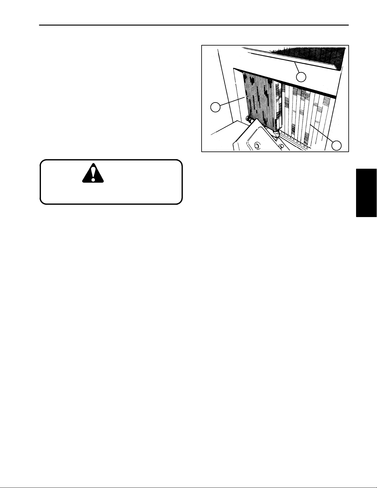
Cleaning the Radiator and Screen
To prevent the engine from overheating, the radiator
screen, radiator, and oil cooler must be kept clean.
Check these components daily . If necessary, clean any
debris off these parts. Clean these components more
frequently in dusty dirty conditions.
1. Remove radiator screen (1).
1
2. Remove four cap screws and nuts that hold the
plastic cover to the radiator assembly. Remove plastic
cover from the radiator assembly.
3. Loosen both quick release knobs on the front end
of the radiator assembly. Now the oil cooler (3) can be
removed from the radiator for cleaning.
CAUTION
Use eye protection such as goggles
when using compressed air.
4. Working from fan side of radiator (2), either spray
the radiator with a hose or blow with compressed air.
5. Thoroughly clean oil cooler (3). Clean off any other
debris that may have collected around components.
6. Reinstall the oil cooler (3). Tighten both quick re-
lease knobs on the front end of the radiator assembly.
7. Reinstall plastic cover onto the radiator assembly.
Reinstall four cap screws and nuts that hold the plastic
cover to the radiator assembly. Tighten fasteners
3
1. Radiator screen
2. Radiator
2
Figure 13
3. Oil cooler
Engine
8. Clean radiator screen (1) and reinstall.
Reelmaster 2300–D/2600–D Page 3 – 11 Engine
Page 30
Changing the Engine Oil and Filter
Change oil and filter initially after the first 20 hours of operation. Thereafter, change oil every 50 hours and filter
every 100 hours.
1. Position machine on a level surface.
2. Locate engine oil drain plug on the bottom of oil pan
and place a collecting pan below it. Remove drain plug
and let oil flow into the collecting pan. When the oil stops
draining, install drain plug.
3. Locate engine filter on the front of the engine. Remove oil filter. Apply a light coat of clean oil to the new
filter seal before screwing it on. DO NOT OVERTIGH-
TEN.
Note: The crankcase capacity is approximately 2.8
qts. (3.0 L) with filter. The engine uses any high–quality
10W30 detergent oil having the American Petroleum Institute – API – “service classification” CD.
4. Add oil to the crankcase.
A. Remove oil fill cap (Fig. 14) and gradually add
small quantities of oil .
B. Check oil level frequently until the level reaches
the FULL mark on dipstick (Fig 15). When removing
the dipstick, wipe it with a clean rag prior to inserting
it to check the oil level.
1
Figure 14
1. Oil fill cap
1
Figure 15
1. Dipstick
C. Push dipstick down into dipstick tube and make
sure it is seated fully when finished (Fig 15).
Checking the Cooling System
"("# " &# "$# &*
#! !# #( ( #!)
% # # # ( !
"#!# # #( # "("#
" !'#( $!#"
CAUTION
If the engine has been running, pressurized hot coolant or steam can escape
when the radiator cap is removed. Burns
may result. Do not open radiator cap
when the radiator or engine is hot.
1. !$( !% !#!
2. % # # !#! !#! #
# # !)# !
1
Figure 16
1. Radiator cap
3. # # % " & !" # "("# DO
NOT OVERFILL
4. "# !#! ##
Engine
Page 3 – 12
Reelmaster 2300–D/2600–D
Page 31

Engine Removal
1. Park machine on a level surface, lower the cutting
units, stop the engine, and remove the key from the start
switch. Chock wheels to keep the machine from moving.
3
3
5
2. Disconnect positive (+) and then negative (–) battery cables at the battery.
3. Gain access to the engine.
A. Open and remove hood from the machine.
B. Remove right side panel to gain access to the
traction pump drive belt.
C. Remove left rear panel (radiator side) which
supports the instrument panel.
4. Remove left fender (1) and fender bracket (2) from
the radiator side of the frame (Fig. 17).
A. Remove cap screw (3) and flange nut (4) holding
the left foot rest (5) to the left fender.
B. Remove remaining cap screws (3) and flange
nuts (4) securing the fender to the fender bracket
and frame. Remove fender from the frame.
C. Remove both cap screws (3) and left fender
bracket (2) from the frame.
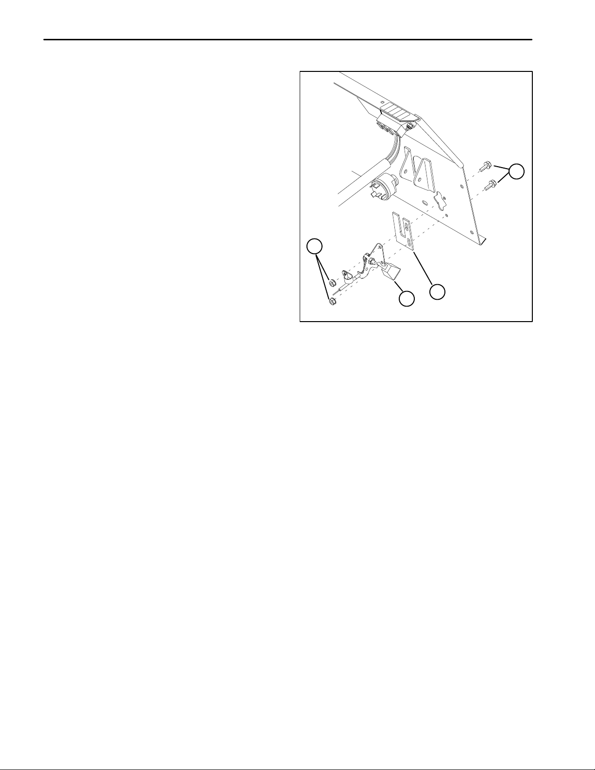
5. Remove cotter pin (1) from adjusting rod (2). Dis-
connect adjusting rod from brake arm (3) (Fig. 18).
6. Remove cap screws (3) and flange nut (4) securing
the left footrest (5) to the frame (Fig. 17). Slide the left
foot rest off the adjusting rod (2) (Fig. 18).
2
6
4
3
1. Left fender
2. Left fender bracket
3. Cap screw
2
4
Figure 17
3
4
4. Flange nut
5. Left footrest
6. Clinch nut
3
1
3
Engine
1
CAUTION
DO NOT open radiator cap or drain coolant
if the engine or radiator is hot. Pressurized
hot coolant can escape and cause burns.
Ethylene–gycol antifreeze is poisonous.
Dispose of it properly or store it in a properly labeled container away from children and
pets.
7. Drain antifreeze from radiator.
1. Cotter pin
2. Adjusting rod
8. Drain hydraulic reservoir.
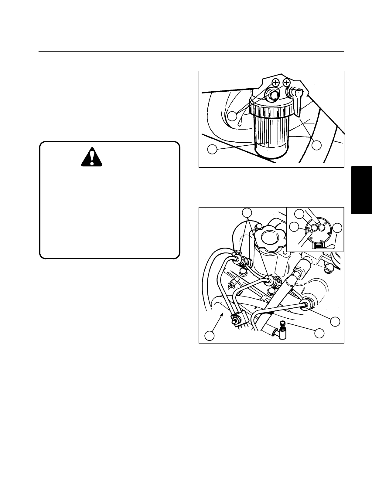
A. Clean hydraulic oil filter and area around the fil-
ter.
A. Slowly remove radiator cap from the radiator.
B. Place clean drain pan below hydraulic oil filter to
B. Place drain pan below the radiator pipe plug. Re-
collect the draining hydraulic oil.
move pipe plug from the bottom of the radiator. Allow antifreeze to drain into the container
C. Remove hydraulic oil filter from bottom of the filter housing with a bottom type filter wrench. Let oil
drain into the drain pan; install filter when drained.
Reelmaster 2300–D/2600–D Page 3 – 13 Engine
Figure 18
3. Brake arm
Page 32

41
25
43
26
FRONT
40
35
RIGHT
39
11
1
2
3
4
5
32
6
7
9
8
44
10
CONNECTED TO
AIR FILTER HOSE
11
13
45
36
38
12
23
18
19
14
19
19
15
16
17
39
31
11
30
37
20
21
29
23
7
28
42
34
36
33
34
13
25
24
27
22 LH
46 RH
LEFT
1. Cap screw
2. Lock washer
3. Clutch washer
4. Engine pulley
5. Cap screw
6. Wire bracket
7. Nut
8. Pop rivet
9. Key
10. Cap screw
11. Flat washer
12. R–clamp
13. Washer
14. Muffler
15. Muffler tube
16. Muffler bracket
Figure 19
17. U–bolt
18. Upper radiator hose
19. Muffler clamp
20. Nut
21. Lock washer
22. Left rear mount bracket
23. Hose clamp
24. Lower radiator hose
25. Engine
26. Throttle cable clamp
27. Flange nut
28. Throttle cable bracket
29. Clevis pin
30. Cotter pin
31. Throttle tab
32. Flat washer
33. Lock washer
34. Front mount bracket
35. Insert nut
36. Cap screw
37. Clutch spindle
38. Hose clamp
39. Cap screw
40. Electric clutch
41. Cap screw
42. Cap screw
43. Cap screw
44. Fuel hose
45. Muffler gasket
46. Right rear mount bracket
Engine
Page 3 – 14
Reelmaster 2300–D/2600–D
Page 33

9. Close fuel shut–off valves under the fuel tank and
on the fuel filter.
10. Disconnect hoses from engine (Fig. 19).
A. Loosen upper hose clamp securing the air filter
hose extending from the engine to the air cleaner.
B. Loosen hose clamps (23). Disconnect upper ra-
diator hose (18) and lower radiator hose (24) from
the engine.
C. Loosen hose clamp (38) and disconnect fuel
hose (44) from the lift pump. Plug hose to prevent
leakage.
D. Loosen hose clamp and disconnect fuel hose
(return) from the injector nozzle piping. Plug hose to
prevent leakage.
CAUTION
2
4
1. Hose clamp
2. Hydraulic return hose
1
3
Figure 20
3. Hydraulic fitting
4. Hydraulic reservoir
The hydraulic fluid may be hot. To avoid
possible burns, allow the hydraulic system to cool before disconnecting hoses.
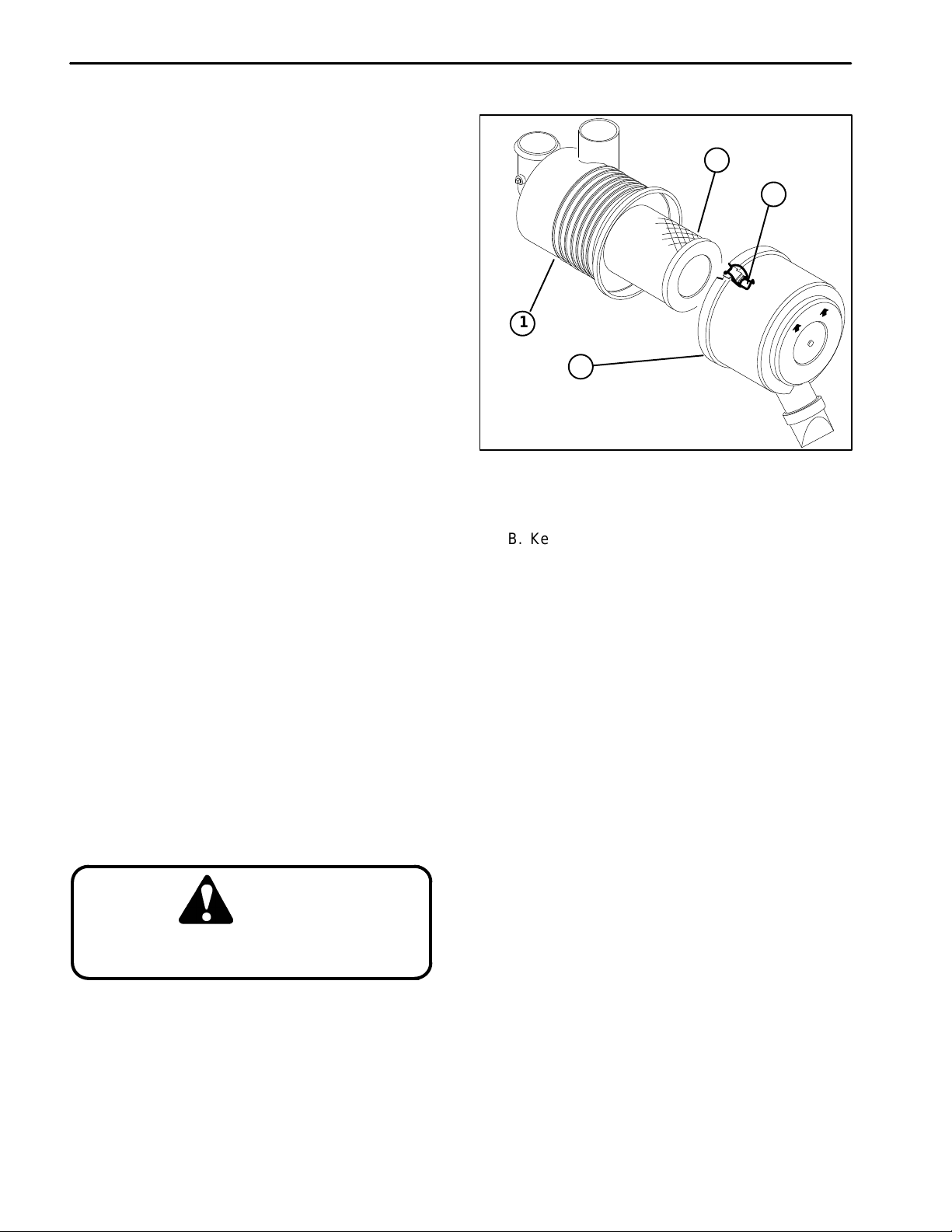
11. Disconnect hydraulic hoses to oil cooler.
A. Loosen hose clamp (1) and disconnect hydraulic
return hose (2) from the hydraulic fitting (3). Plug
hose and fitting to prevent leakage and contamination (Fig. 20).
B. Loosen hose clamp (1) and disconnect hydraulic
supply hose (2) from the hydraulic elbow fitting (3).
Plug hose and fitting to prevent leakage and contamination (Fig. 21).
CAUTION
The muffler and muffler tube may be hot.
To avoid possible burns, allow the exhaust system to cool before working on
the muffler and muffler tube.
12. Remove exhaust system (Fig. 19).
2
1
4
3
Figure 21
1. Hose clamp
2. Hydraulic supply hose
3. Hydraulic elbow fitting
4. Hydraulic manifold
D. Remove cap screws (39) and flat washers (11)
from the muffler and exhaust manifold. Remove
muffler and muffler gasket (53) from the engine.
Engine
A. Remove muffler clamp (19) from the muffler (14)
and muffler tube (15).
B. Loosen nut (20) and U–clamp (17). Separate
muffler tube from muffler and slide muffler tube
through U–clamp.
C. Remove cap screws (36) and washers (13) from
the muffler and right rear mount bracket (46).
13. Disconnect throttle cable (Fig. 19).
A. Loosen cap screw (43) enough to separate the
throttle cable from the throttle cable clamp (30).
B. Remove cotter pin (30) from clevis pin (29). Re-
move clevis pin, throttle tab (31), and throttle cable
from the engine governor lever.
C. Secure throttle cable away from the engine.
Reelmaster 2300–D/2600–D Page 3 – 15 Engine
Page 34

14. Disconnect electrical connections (Fig. 19).
Note: Label all electrical leads for reassembly pur-
poses.
A. Disconnect connector with blue leads from the
alternator.
B. Disconnect connector with blue/white leads
from the traction clutch.
C. Disconnect connector from the front lift cylinder
microswitch.
D. Remove white/black lead from the temperature
sender located on the top of the water pump.
E. Remove tan lead from the high temperature shut
down switch located on the water pump behind the
fan.
F . Remove purple lead from the fuel valve solenoid
located above the lift pump.
G. Remove brown lead from the oil pressure switch
located on the front of the cylinder head.
4
2
1. Cap screws
2. Whiz nut
1
3
Figure 22
3. Radiator rear bracket
4. Frame
H. Remove white lead from the glow plugs located
on the front traction pump side of the cylinder head.
I. Remove gray , red, and white leads from the engine starter solenoid located on below the exhaust
manifold.
J. Disconnect battery ground from the traction
clutch side of the cylinder head or the fan side of the
cylinder block.
K. Remove cap screw (10) and flat washer (11)
from R–clamp (12). Pull wiring harness and hydraulic hoses away from the engine to keep them from
snagging the engine when it is removed. The harness and hoses may be tied to the reservoir support
brackets.
15. Remove radiator assembly.
A. Support the radiator assembly while removing
fasteners.
B. Remove cap screws (1) and whiz nuts (2) from
the radiator rear bracket (3) and frame (4) (Fig. 22).
3
1
1. Carriage bolt
2. Whiz nut
2
4
Figure 23
3. Radiator bracket
4. Frame
C. Remove carriage bolts (1) and whiz nuts (2) from
the radiator bracket (3) and frame (4) (Fig. 23).
D. Pull radiator assembly out and then up from the
engine to prevent the engine cooling fan from catching the radiator top and bottom shrouds.
Engine
Page 3 – 16
Reelmaster 2300–D/2600–D
Page 35

16. Remove traction pump drive belt as described in
Traction (Electric) Clutch of the Service and Repairs
section of Chapter 5 – Electrical System.
17. Remove engine (Fig. 19)
A. Attach short section of chain between both lift
tabs (1) located on each end of the cylinder head (2)
(Fig. 24)
B. Connect a hoist or chain fall at the center of the
short section of chain. Apply enough tension on the
short chain so that the engine will be supported
when the cap screws (42) securing the engine
mount brackets (22, 34, and 46) are removed.
1
2
C. Remove cap screws (42) and flange nuts (27)
from the engine mount brackets (22, 34, and 46)
and the frame.
Note: One person should operate the chain fall or
hoist while another person guides the engine out of the
frame.
Note: Be careful not to damage the engine, fuel lines,
hydraulic hoses, electrical harness or other parts while
removing the engine.
D. Remove engine (25) from the frame.
E. Mount engine onto an engine rebuilding stand.
Figure 24
1. Lifting tab 2. Cylinder head
Engine
Reelmaster 2300–D/2600–D Page 3 – 17 Engine
Page 36

Engine Reinstallation
1. Make sure machine is parked on a level surface with
cutting units lowered, and key removed from the start
switch. Chock wheels to keep the machine from moving.
2. Make sure that all parts remove from the engine
during maintenance or rebuilding are reinstalled to the
engine.
3. If mount brackets (22, 34, and 46) were removed reinstall them as follows (Fig. 19):
A. For front mount brackets (34), secure brackets
to the engine (25) with cap screws (36), lock washers (33) and washers (13). T orque cap screws from
34 to 42 ft–lb (4.7 to 5.8 kg–m).
B. For left rear mount bracket (22), secure bracket
to the engine (25) with two cap screws (36), lock
washers (33) and washers (13) through the left
holes. Leave the right holes open for the muffler.
Torque cap screws from 34 to 42 ft–lb (4.7 to 5.8
kg–m).
C. For right rear mount bracket (46), secure brackets to the engine (25) with cap screws (36), lock
washers (33) and washers (13). Leave cap screws
loose enough so that the position of the bracket
can be adjusted after the engine is installed.
4. Reinstall engine (Fig. 19)
A. Attach short section of chain between both lift
tabs (1) located on each end of the cylinder head (2)
(Fig. 24)
B. Connect a hoist or chain fall at the center of the
short section of chain. Apply enough tension on the
short chain so that the engine will be supported
when the engine is removed from the engine rebuilding stand. Remove engine from the engine rebuilding stand.
Note: One person should operate chain fall or hoist
while another person guides the engine into the frame.
E. On the right rear mount bracket (46), tighten cap
screws (36). Torque cap screws from 34 to 42 ft–lb
(4.7 to 5.8 kg–m).
5. Reinstall radiator assembly.
A. Place radiator assembly down and then into the
engine to prevent the engine cooling fan from catching the radiator top and bottom shrouds.
B. Connect air filter hose extending from the engine
to the air cleaner. Tighten hose clamp.
C. Support the radiator assembly while installing
the fasteners.
D. Install carriage bolts (1) and whiz nuts (2) to the
radiator bracket (3) and frame (4) (Fig. 23).
E. Install cap screws (1) and whiz nuts (2) to the radiator rear bracket (3) and frame (4) (Fig. 22).
6. Reconnect electrical connections (Fig. 19).
A. Untie harness and hoses from the reservoir sup-
port brackets. Pull wiring harness and hydraulic
hoses into position; keep them from contacting
moving parts. Install cap screw (10) and flat washer
(11) to R–clamp (12) and tighten to cylinder head.
B. Reconnect connector with blue leads to the alternator.
C. Reconnect connector with blue/white leads to
the traction clutch.
D. Reconnect connector to the front lift cylinder microswitch.
E. Reconnect white/black lead to the temperature
sender located on the top of the water pump.
F . Reconnect tan lead to the high temperature shut
down switch located on the water pump behind the
fan.
Note: Be careful not to damage the engine, fuel lines,
hydraulic hoses, electrical harness or other parts while
reinstalling the engine.
C. Reinstall engine (25) onto the frame. Make sure
fastener holes of the mount brackets (22, 34, and
46) are aligned with the holes on the frame.
D. Secure cap screws (42) and flange nuts (27) to
the mount brackets (22, 34, and 46) and frame.
Engine
Page 3 – 18
G. Reconnect purple lead to the fuel valve solenoid
located above the lift pump.
H. Reconnect brown lead to the oil pressure switch
located on the front of the cylinder head.
I. Reconnect white lead to the glow plugs located
on the front right side of the cylinder head.
Reelmaster 2300–D/2600–D
Page 37

J. Reconnect gray, red, and white leads to the engine starter solenoid located on below the exhaust
manifold.
K. Reconnect battery ground to the traction clutch
side of the cylinder head or the left side of the cylinder block.
7. Reconnect throttle cable (Fig. 19).
1 1. Open fuel shut–off valves under the fuel tank and on
the fuel filter.
12. Fill hydraulic reservoir with hydraulic fluid as described in the General Information section of Chapter 4
– Hydraulic System. Check reservoir for leaks.
13. Add antifreeze to radiator as described in Checking
the Cooling System.
A. Run throttle cable to engine (25).
B. Reinstall clevis pin (29), throttle tab (30), and
throttle cable to the engine governor lever. Reinstall
and lock cotter pin (31) to the clevis pin.
C. Install throttle cable into the throttle cable clamp
(26). Tighten cap screw (43).
8. Reinstall exhaust system (Fig. 19).
A. Position muffler (14) and muffler gasket (45)
onto the exhaust manifold. Install capscrews (39)
and flat washers (11) to the muffler and exhaust
manifold. Tighten cap screws.
B. Reinstall cap screws (36) and washers (13) into
the muffler and right rear mount bracket (46).
C. Slide muffler tube through the U–clamp (17).
Connect muffler tube to the muffler . Tighten nut (20)
and U–clamp.
D. Reinstall muffler clamp (19) to the muffler (14)
and muffler tube (15).
9. Reconnect hydraulic hoses from the oil cooler.
14. Slide the left foot rest (5) (Fig. 17) onto the adjusting
rod (2) (Fig. 18). Reinstall cap screws (3) and flange nut
(4) securing the left footrest (5) to the frame. Tighten cap
screws (Fig. 17).
15. Connect adjusting rod to brake arm (3) Install and
lock cotter pin (1) to the adjusting rod (2) (Fig. 18).
16. Reinstall fender bracket (2) and left fender (1) to the
radiator side of the frame (Fig. 17).
A. Secure both cap screws (3) and left fender
bracket (2) to the frame.
B. Reinstall remaining cap screws (3) and flange
nuts (4) securing the fender to the fender bracket
and frame.
C. Secure cap screw (3) and flange nut (4) to the
left foot rest (5) and the left fender (1).
17. Replace traction pump drive belt as described in
Traction (Electric) Clutch of the Service and Repairs
section of Chapter 5 – Electrical System.
18. Adjust traction pump drive belt as described in the
Adjustment section of Chapter 4 – Hydraulic system.
Engine
A. Unplug hydraulic hose (2) and hydraulic elbow
fitting (3). Connect hydraulic supply hose to the hydraulic elbow fitting. Tighten hose clamp (1) (Fig.
21).
B. Unplug hydraulic return hose (2) and hydraulic
fitting (3). Connect hydraulic return hose to the hydraulic fitting. Tighten hose clamp (1) (Fig. 20).
10. Connect hoses to the engine (Fig. 19).
A. Connect fuel hose (return) to the injector nozzle
piping and tighten hose clamp.
B. Unplug fuel hose (44). Connect fuel hose to the
lift pump and tighten hose clamp (38).
C. Connect upper radiator hose (18) and lower ra-
diator hose (24) to the engine. Tighten hose clamps
(23).
D. Connect air filter hose to the engine (25).
Reelmaster 2300–D/2600–D Page 3 – 19 Engine
19. Connect negative (–) and then positive (+) battery
cables at the battery.
20. Adjust hand brake as described in the Adjustment
section of Chapter 6 – Wheels and Brakes.
21. Adjust throttle linkage as described in the Adjustment section of this chapter.
22. Bleed fuel system. See Bleeding the Fuel System.
23. Check oil level as described in Changing the Engine
OIl and Filter.
24. Replace access covers to the engine.
A. Reinstall left rear panel (radiator side) which
supports the instrument panel.
B. Reinstall right side panel which accesses the
traction pump drive belt.
C. Reinstall hood to the machine and close.
Page 38

Engine
Page 3 – 20
Reelmaster 2300–D/2600–D
Page 39

Table of Contents
Chapter 4
Hydraulic System
SPECIFICATIONS 2. . . . . . . . . . . . . . . . . . . . . . . . . . . .
GENERAL INFORMATION 3. . . . . . . . . . . . . . . . . . . . .
Hydraulic Hoses 3. . . . . . . . . . . . . . . . . . . . . . . . . . . .
Hydraulic Fitting Installation 3. . . . . . . . . . . . . . . . . .
Checking the Hydraulic System Fluid 5. . . . . . . . . .
Changing the Hydraulic System Fluid and Filter 6.
Pushing or Towing the Traction Unit 6. . . . . . . . . . .
HYDRAULIC SCHEMATIC 7. . . . . . . . . . . . . . . . . . . . .
HYDRAULIC FLOW DIAGRAMS 8. . . . . . . . . . . . . . . .
Raise Cutting Units 8. . . . . . . . . . . . . . . . . . . . . . . . . .
Traction Forward 10. . . . . . . . . . . . . . . . . . . . . . . . . . .
Traction Reverse 12. . . . . . . . . . . . . . . . . . . . . . . . . . .
Mow 14. . . . . . . . . . . . . . . . . . . . . . . . . . . . . . . . . . . . . .
SPECIAL TOOLS 16. . . . . . . . . . . . . . . . . . . . . . . . . . . .
Hydraulic Pressure Test Kit 16. . . . . . . . . . . . . . . . . .
Hydraulic Tester – Pressure and Flow 16. . . . . . . .
TROUBLESHOOTING 17. . . . . . . . . . . . . . . . . . . . . . . .
Hydraulic Oil Leaks 17. . . . . . . . . . . . . . . . . . . . . . . . .
Foaming Hydraulic Fluid 17. . . . . . . . . . . . . . . . . . . .
Hydraulic System Operates Hot 17. . . . . . . . . . . . . .
Neutral Is Difficult to Find or Operates in One
Direction Only 17. . . . . . . . . . . . . . . . . . . . . . . . . . . .
Traction Response Is Sluggish 17. . . . . . . . . . . . . . .
No Traction in Either Direction 17. . . . . . . . . . . . . . .
Wheel Motor Will Not Turn 18. . . . . . . . . . . . . . . . . .
Wheel Motor Will Not Hold Load In Neutral 18. . . .
Noisy Wheel Motor Drive Pump (Cavitation) 18. . .
Reels Will Not Turn 18. . . . . . . . . . . . . . . . . . . . . . . . .
Reel Speed Is Erratic 18. . . . . . . . . . . . . . . . . . . . . . .
Reel Motor Case Drain Flow Is Excessive 18. . . . .
Cutting Units Will Not Lift or Lift Slowly 18. . . . . . . .
Cutting Units Raise, but Will Not Stay Up 18. . . . . .
TESTING 19. . . . . . . . . . . . . . . . . . . . . . . . . . . . . . . . . . .
Test No. 1: Traction Pump Flow 20. . . . . . . . . . . . . .
Test No. 2: Charge Pump Flow and
Implement Relief Pressure 22. . . . . . . . . . . . . . . . .
Test No. 3: Charge Relief Pressure 24. . . . . . . . . . .
Test No. 4: Real Drive Pump Efficiency 26. . . . . . .
Test No. 5: Manifold Relief Valve Pressure 28. . . .
Test No. 6: Cross–over Relief Pressures 30. . . . . .
Test No. 7: Reel Motor Case Drain 32. . . . . . . . . . .
ADJUSTMENTS 34. . . . . . . . . . . . . . . . . . . . . . . . . . . . .
Transmission for Neutral 34. . . . . . . . . . . . . . . . . . . .
Traction Pedal 35. . . . . . . . . . . . . . . . . . . . . . . . . . . . .
Traction Pedal Damper 35. . . . . . . . . . . . . . . . . . . . .
Hydraulic Pump Drive Belt 36. . . . . . . . . . . . . . . . . .
SERVICE AND REPAIRS 37. . . . . . . . . . . . . . . . . . . . .
Traction/Charge Pump 37. . . . . . . . . . . . . . . . . . . . . .
Wheel Motor 44. . . . . . . . . . . . . . . . . . . . . . . . . . . . . .
2WD/3WD Two Position Valve 54. . . . . . . . . . . . . . .
Reel Motor Drive Pump 57. . . . . . . . . . . . . . . . . . . . .
Reel Motor 60. . . . . . . . . . . . . . . . . . . . . . . . . . . . . . . .
Hydraulic Manifold 63. . . . . . . . . . . . . . . . . . . . . . . . .
Front Lift Cylinder 67. . . . . . . . . . . . . . . . . . . . . . . . . .
Rear Lift Cylinder 71. . . . . . . . . . . . . . . . . . . . . . . . . .
Control and Implement Relief Valves 74. . . . . . . . .
Hydraulic Reservoir 77. . . . . . . . . . . . . . . . . . . . . . . .
Flushing the Hydraulic System 79. . . . . . . . . . . . . . .
Hydraulic System Start–up 80. . . . . . . . . . . . . . . . . .
System
Hydraulic
Reelmaster 2300–D/2600–D Hydraulic SystemPage 4 – 1
Page 40

Specifications
Item Description
Traction Pump Variable displacement piston pump
Maximum Operating Pressure 3000 PSI (207 bar)
Maximum Intermittent Pressure 5000 PSI (345 bar)
Maximum Rated Speed 3600 RPM
Rated Flow @ Maximum Rated Speed and Pressure 17 GPM (64 LPM)
Charge Pump Gerotor pump
Maximum Operating Pressure 500 PSI (34.5 bar)
Maximum Rated Speed 3600 RPM
Rated Flow @ Maximum Rated Speed and Pressure 3.5 GPM (13.2 LPM)
Charge Pressure 100 to 150 PSI (6.9 to 10.0 bar)
Implement (Lift) Relief Valve Differential area relief valve
Implement Relief Pressure 450 – 525 PSI (31.1 to 36.2 bar)
Wheel Motors Orbital rotor pump (with shuttle valve on left front motor)
Maximum Operating Pressure 2000 PSI (138 bar)
Maximum Intermittent Pressure 3000 PSI (207 bar)
Maximum Rated Speed 267 RPM
Rated Flow @ Maximum Rated Speed and Pressure 15 GPM (57 LPM)
Reel Motor Drive Pump Positive displacement gear type pump
Maximum Operating Pressure 4000 PSI (276 bar)
Maximum Intermittent Pressure 4400 PSI (304 bar)
Maximum Rated Speed 4000 RPM
Rated Flow @ Maximum Rated Speed and Pressure 8.5 GPM (32 LPM)
Hydraulic Manifold Relief Valve Differential area relief valve
Cutting Circuit Relief Pressure 2700 to 3300 PSI (186.3 to 227.7 bar)
Reel Motor Gear motor
Cross–over Relief Pressure 1350 to 1650 PSI (93.2 to 113.9 bar)
Maximum Operating Pressure 2250 PSI (155 bar)
Maximum Intermittent Pressure 3000 PSI (207 bar)
Maximum Rated Speed 3000 RPM
Rated Flow @ Maximum Rated Speed and Pressure 28.6 GPM (108 LPM)
Lift Control Valve Spool type directional control valve
Hydraulic Filter 10 Micron spin–on cartridge type
Hydraulic Oil * Mobil 424/Shell Donax TD or equivalent
Hydraulic Reservoir Reservoir capacity 2.3 gal. U.S. (8.7 L)
Total system capacity approximately 3.3 gal. U.S. (12.5 L)
Reelmaster 2300–D/2600–DHydraulic System Page 4 – 2
Page 41

General Information
Hydraulic Hoses
Hydraulic hoses are subject to extreme conditions such
as pressure differentials during operation and exposure
to weather, sun, chemicals, very warm storage conditions, or mishandling during operation or maintenance.
These conditions can cause damage or premature deterioration. Some hoses are more susceptible to these
conditions than others. Inspect the hoses frequently for
signs of deterioration or damage.
When replacing a hydraulic hose, be sure that the hose
is straight (not twisted) before tightening the fittings.
This can be done by observing the imprint on the hose.
Use two wrenches; hold the hose straight with one and
tighten the hose swivel nut onto the fitting with the other.
W ARNING
Before disconnecting or performing any
work on hydraulic system, all pressure in
system must be relieved by stopping the
engine and lowering or supporting the
box and/or other attachment.
Keep body and hands away from pin hole
leaks or nozzles that eject hydraulic fluid
under high pressure. Use paper or cardboard, not hands, to search for leaks.
Hydraulic fluid escaping under pressure
can have sufficient force to penetrate the
skin and cause serious injury. If fluid is
injected into the skin, it must be surgically removed within a few hours by a doctor
familiar with this type of injury . Gangrene
may result from such an injury.
Hydraulic Fitting Installation
O–Ring Face Seal
1. Make sure both threads and sealing surfaces are
free of burrs, nicks, scratches, or any foreign material.
2. Make sure the O–ring is installed and properly
seated in the groove. It is recommended that the O–ring
be replaced any time the connection is opened.
3. Lubricate the O–ring with a light coating of oil.
4. Put the tube and nut squarely into position on the
face seal end of the fitting and tighten the nut until finger
tight.
5. Mark the nut and fitting body. Hold the body with a
wrench. Use another wrench to tighten the nut to the correct flats from finger tight (F .F.F .T .). The markings on the
nut and fitting body will verify that the connection has
been tightened.
Size F.F.F.T .
4 (1/4 in. nominal hose or tubing) .75 +
6 (3/8 in.) .75 +
8 (1/2 in.) .75 +
10 (5/8 in.) 1.00 +
12 (3/4 in.) .75 +
16 (1 in.) .75 +
.25
.25
.25
.25
.25
.25
Nut
Sleeve
Seal
Body
Figure 1
Final
Position
Mark Nut
and Body
Extend Line
Initial
Position
Finger Tight After Proper Tightening
Figure 2
System
System
Hydraulic
Hydraulic
Reelmaster 2300–D/2600–D Hydraulic SystemPage 4 – 3
Page 42

SAE Straight Thread O–Ring Port – Non–adjustable
1. Make sure both threads and sealing surfaces are
free of burrs, nicks, scratches, or any foreign material.
2. Always replace the O–ring seal when this type of fitting shows signs of leakage.
3. Lubricate the O–ring with a light coating of oil.
O–Ring
4. Install the fitting into the port and tighten it down full
length until finger tight.
5. Tighten the fitting to the correct flats from finger tight
(F .F .F .T .).
Size F .F .F .T .
4 (1/4 in. nominal hose or tubing) 1.00 +
6 (3/8 in.) 1.50 +
8 (1/2 in.) 1.50 +
10 (5/8 in.) 1.50 +
12 (3/4 in.) 1.50 +
16 (1 in.) 1.50 +
.25
.25
.25
.25
.25
.25
SAE Straight Thread O–Ring Port – Adjustable
1. Make sure both threads and sealing surfaces are
free of burrs, nicks, scratches, or any foreign material.
2. Always replace the O–ring seal when this type of fitting shows signs of leakage.
3. Lubricate the O–ring with a light coating of oil.
4. Turn back the jam nut as far as possible. Make sure
the back up washer is not loose and is pushed up as far
as possible (Step 1).
Figure 3
Lock Nut
Back–up Washer
O–Ring
5. Install the fitting into the port and tighten finger tight
until the washer contacts the face of the port (Step 2).
6. To put the fitting in the desired position, unscrew it
by the required amount, but no more than one full turn
(Step 3).
7. Hold the fitting in the desired position with a wrench
and turn the jam nut with another wrench to the correct
flats from finger tight (F.F.F.T.) (Step 4).
Size F.F.F.T.
4 (1/4 in. nominal hose or tubing) 1.00 +
6 (3/8 in.) 1.50 +
8 (1/2 in.) 1.50 +
10 (5/8 in.) 1.50 +
12 (3/4 in.) 1.50 +
16 (1 in.) 1.50 +
.25
25
.25
.25
.25
.25
Figure 4
Step 3Step 1
Step 2 Step 4
Figure 5
Reelmaster 2300–D/2600–DHydraulic System Page 4 – 4
Page 43

Checking the Hydraulic System Fluid
The hydraulic system is designed to operate on anti–
wear hydraulic fluid. The machine’s reservoir is filled at
the factory with approximately 3.3 gallons (12.5 liters) of
Mobil 424 hydraulic fluid. Check level of hydraulic
fluid before engine is first started and daily thereafter.
Group 1 Hydraulic Fluid (Recommended for ambient temperatures consistently below 100 F.):
ISO type 46/68 anti–wear hydraulic fluid
Mobil Mobil Fluid 424
Amoco Amoco 1000
International Harvester Hy–Tran
Texaco TDH
Shell Donax TD
Union OIl Hydraulic/T ractor Fluid
Chevron Tractor Hydraulic Fluid
BP Oil BP HYD TF
Boron OIl Eldoran UTH
Exxon Torque Fluid
Conoco Power–Tran 3
Kendall Hyken 052
Phillips HG Fluid
Note: The fluids within this group are interchangeable.
Group 2 Hydraulic Fluid (Biodegradable):
1
2
Figure 6
1. Hydraulic reservoir cap 2. Sight gauge
IMPORTANT: Use only types of hydraulic fluids
specified. Other fluids could cause system damage.
Note: A red dye additive for the hydraulic system fluid
is available in 2/3 oz bottles. One bottle is sufficient for
4 to 6 gallons (15 to 22 liters) of hydraulic fluid. Order
Part No. 44–2500 from your Authorized T oro Distributor .
1. Position machine on a level surface. Make sure engine is off and parking brake is set.
2. Check level of the fluid by viewing into the sight
gauge. If the fluid is cold, the level should be at the bottom of the gauge. If the fluid is hot, the level should be
at the center of the gauge.
System
Hydraulic
ISO VG 32/46 anti–wear hydraulic fluid
Mobil EAL 224 H
IMPORTANT: Due to the nature of biodegradable
fluids, it is critical that the fluid be changed at the
recommended intervals or severe hydraulic component damage may occur.
Note: The fluid in this group is not compatible with the
fluids in group 1.
IMPORTANT: These hydraulic fluids are specified
to allow optimal operation of the machine in a wide
range of temperatures encountered. The group 1
fluids are a multi–viscosity hydraulic fluids which
allows operation at lower temperatures without the
increased viscosity that is associated with straight
viscosity fluids.
Note: When changing from one type of hydraulic fluid
to the other, be certain to remove all the old fluid from the
system, because some brands of one type are not completely compatible with some brands of the other type of
hydraulic fluid.
Reelmaster 2300–D/2600–D Hydraulic SystemPage 4 – 5
3. If fluid level is not at center of gauge, remove cap
from the hydraulic fluid reservoir and slowly fill reservoir
with Mobil 424 or equivalent hydraulic fluid until level
reaches center of sight gauge. DO NOT OVERFILL
IMPORTANT: To prevent system contamination,
clean top of hydraulic fluid containers before puncturing. Assure pour spout and funnel are clean.
4.Install reservoir cap. Wipe up any fluid that may have
spilled.
Page 44

Changing the Hydraulic System Fluid and Filter
The hydraulic system filter must be changed initially , after the first five hours of operation, and thereafter every
200 hours of operation or yearly , whichever comes first.
Use a genuine Toro oil filter for replacement. The hydraulic fluid must be changed every 400 hours of operation or yearly, whichever comes first.
1. Park the machine on a level surface, lower the cutting units, set parking brake and turn the engine off.
2. If only the filter is to be changed, remove reservoir
cap and insert reservoir plug (Fig. 7), to block outlet. This
will retain most of the fluid in reservoir when filter is removed.
3. Clean the area around the hydraulic oil filter. Remove filter from the bottom of the filter housing and allow
the oil to flow into a drain pan. Use a bottom type filter
wrench. Dispose of the oil filter properly.
4. Apply a film of oil on the filter gasket. Install filter by
hand until gasket contacts the mounting head; then
tighten filter an additional three–fourths turn.
1
2
Figure 7
1. Reservoir plug 2. Reservoir outlet
5. Fill the reservoir to proper level, refer to Checking
the Hydraulic System Fluid.
6. Place all controls in neutral or disengaged position
and start engine. Run engine at lowest possible RPM to
purge the system of air.
7. Run engine until lift cylinders extend and retract and
forward and reverse wheel motion is achieved.
8. Stop the engine and check the oil level in reservoir,
add oil if necessary.
9. Check all connections for leaks.
Pushing or Towing the Traction Unit
In case of emergency, the Reelmaster 2300–D can be
towed for a short distance. However, Toro does not recommend this as a standard procedure.
IMPORTANT: Do not tow the machine faster than
2–3 mph because drive system may be damaged. If
machine must be moved a considerable distance,
transport it on a truck or trailer.
1
Figure 8
1. Hydraulic oil filter
1. Locate by–pass valve on pump and rotate it 90_
so the by–pass valve is horizontal.
2. Before the starting engine, close by–pass valve by
rotating it 90_ so the by–pass valve is vertical. Do not
start engine when valve is open.
1
Figure 9
1. By–pass valve
Reelmaster 2300–D/2600–DHydraulic System Page 4 – 6
Page 45

Hydraulic Schematic
(SHOWN IN 3WD)
2WD/3WD SELECTOR
BOTTOM
TOP
WHEEL MOTOR
12 in3
REAR
[197cc]
LEFT WHEEL MOTOR SCHEMATIC
REEL MOTOR SCHEMATIC
CROSS–OVER RELIEF
1500 PSI
[25.2cc]
1.54 in3
REEL MOTORS
FORWARD
REVERSE
IN (FRONT)
VAL VE TOP A
2.1 GPM
PC FLOW CONTROL
BOTTOM B
OUT (REAR)
TOW VALVE
TOP
BOTTOM
2
475 psi
REEL LIFT
CONTROL VALVE
CHARGE RELIEF
LIFT RELIEF
FRONT
100–150 psi
FILTER
10 MICRON NOM
TOP
2.3 GALLON
RESERVOIR
LOW PRESSURE
BOTTOM
.42 IN3
[6.9CC]
CHARGE PUMP
[8.7 LITER]
1.24 in3
[20.3 cc)
TRACTION PUMP
COOLER
FRONT
.49 in3
[8.0cc]
GEAR PUMP
G1
REEL SPEED CONTROLLER
P1
1
RH
M2
D1
FCI
M1
M5
MD1
BACKLAPPING
LC1
D3
VALVE
LOGIC
VALVE
R1
CTR
LH
M6
M4
M3
D2
System
Hydraulic
FLOW CONTROL VALVE
REEL
REEL
VALVE
ON–OFF
RELIEF
3000 psi
S1
RIGHT
WHEEL MOTOR
12 in3
[197cc]
OUTER
A–LOWER
LIFT CYL
FRONT
B–UPPER
INNER
LIFT CYL
REAR
Reelmaster 2300–D/2600–D Hydraulic SystemPage 4 – 7
LINE)
(REAR
FORWARD
LINE)
(FRONT
REVERSE
12 in3
[197cc]
LEFT
WHEEL MOTOR
REAR WHEELDRIVE CIRCUIT IS
de–energized
Solenoid S1 is shown
Hydraulic Schematic
Reelmaster 2300–D/2600–D
T2
NOT USED ON 2WD UNITS
Page 46

Hydraulic Flow Diagrams
Raise Cutting Units
The charge pump is part of the traction pump and is directly coupled to it. It supplies hydraulic pressure for
raising and lowering cutting units and maintaining 100
to 150 PSI to the low pressure side of the traction circuit
(piston pump). The pump takes its suction through a filter from the reservoir.
During conditions of not lifting or lowering cutting units,
flow from the charge pump goes to the control valve and
is by–passed (control valve position not shown) directly
to the suction of the piston pump and the charge relief
valve.
When the cutting units are to be raised, the control valve
spool is positioned down and flow is directed out the top
of the control valve to the lower and outer portions of the
lift cylinders. Hydraulic pressure against the cylinder
pistons pushes the shafts out. At the same time, the pistons push the hydraulic fluid in the upper and inner portions of the lift cylinders out and through the control valve
to the piston pump suction. When the control valve lever
is released, spring action returns the spool to the center
position and by–passes flow back to the piston pump
suction. Lift cylinder movement is stopped. The cylinder
position is locked in place since there is no complete circuit of flow to and from the lift cylinders.
Circuit operation for lowering the lift cylinders is similar
to raising them. However, the control valve spool is
shifted up and flow is reversed to and from the lift cylinders, thus moving the cutting units down.
Reelmaster 2300–D/2600–DHydraulic System Page 4 – 8
Page 47

(SHOWN IN 3WD)
2WD/3WD SELECTOR
BOTTOM
TOP
WHEEL MOTOR
12 in3
REAR
[197cc]
LEFT WHEEL MOTOR SCHEMATIC
REEL MOTOR SCHEMATIC
CROSS–OVER RELIEF
1500 PSI
[25.2cc]
1.54 in3
REEL MOTORS
FORWARD
REVERSE
IN (FRONT)
REEL LIFT
CONTROL VALVE
VAL VE TOP A
2.1 GPM
PC FLOW CONTROL
BOTTOM B
OUT (REAR)
TOW VALVE
TOP
BOTTOM
2
475 psi
1
LIFT RELIEF
FRONT
FILTER
TOP
100–150 psi
CHARGE RELIEF
RESERVOIR
10 MICRON NOM
LOW PRESSURE
BOTTOM
.42 IN3
[6.9CC]
CHARGE PUMP
[8.7 LITER]
2.3 GALLON
1.24 in3
TRACTION PUMP
(20.3 cc)
COOLER
FRONT
.49 in3
[8.0cc]
GEAR PUMP
G1
REEL SPEED CONTROLLER
P1
RH
M2
D1
FCI
M1
M5
MD1
BACKLAPPING
LC1
D3
VALVE
LOGIC
VALVE
R1
CTR
LH
M6
M4
M3
D2
FLOW CONTROL VALVE
REEL
REEL
VALVE
ON–OFF
RELIEF
3000 psi
S1
System
Hydraulic
12 in3
[197cc]
RIGHT
WHEEL MOTOR
OUTER
A–LOWER
LIFT CYL
FRONT
B–UPPER
INNER
LIFT CYL
REAR
Reelmaster 2300–D/2600–D Hydraulic SystemPage 4 – 9
LINE)
(REAR
FORWARD
LINE)
(FRONT
REVERSE
WHEEL MOTOR
LEFT
12 in3
[197cc]
T2
High Pressure
Low Pressure (Charge)
Return or Suction
Flow
Solenoid S1 is shown de–energized
Raise Cutting Units
Reelmaster 2300–D/2600–D
Control valve is positioned up
Page 48

Traction Forward
The traction pump is driven by the engine through the
pulley , pump drive belt, and electric clutch. The traction
circuit of the hydraulic system acts essentially as a
closed loop. Taking its suction directly from the return
side of the wheel motors of the traction circuit, the traction pump supplies oil flow to the wheel motors through
the supply side of the traction circuit.
With the engine running, clutch engaged, and traction
pedal in the neutral position, the traction pump supplies
no flow to the wheel motors. When the traction pedal is
pressed to the forward position, the linkage from the
pedal positions the swash plate in the traction motor so
oil flows out the top port of the pump. Oil flow out of the
top port goes to the wheel motors and turns them in the
forward direction. The 2WD/3WD selector valve allows
flow to the rear wheel in the 3WD position and by–
passes the rear wheel in the 2WD position.
Oil flowing out of the wheel motors returns to the bottom
port of the traction pump and is continuously pumped
out the top port. However, oil flow out of the rear wheel
motor must pass through the check valve portion of the
PC flow controller before returning to the traction pump.
A small amount of hydraulic oil leaves the traction circuit
through the bi–directional shuttle valve in the front left
wheel motor. This oil is cooled as it flows through the
cooler and returned to the reservoir.
Filtered hydraulic oil is supplied to the traction circuit
from the charge pump though the lift control valve and
back through the charge circuit check valves. This filtered oil replaces oil losses from flow through the shuttle
valve and small amounts of leakage. The charge pump
and shuttle valve circuits allow for indirect cooling and
filtering of the traction circuit.
In the forward direction, the PC flow controller has a special function. When a unit is moving downhill, the operator will return the traction pedal to the neutral position.
In this situation, the front wheel motors act as hydraulic
pumps and reverse the oil flow through the traction circuit. The PC flow controller will restrict flow to the rear
motor sufficiently, so the reverse flow is by–passed
through the 2WD/3WD selector (check) valve around
the rear wheel motor. This action will prevent a loss of
steering control should the rear motor turn in the reverse
direction. As a result, there is no 3WD in reverse
Reelmaster 2300–D/2600–DHydraulic System Page 4 – 10
Page 49
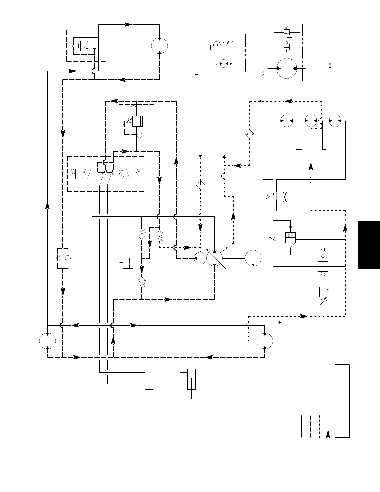
(SHOWN IN 3WD)
2WD/3WD SELECTOR
BOTTOM
TOP
WHEEL MOTOR
12 in3
REAR
[197cc]
LEFT WHEEL MOTOR SCHEMATIC
REEL MOTOR SCHEMATIC
CROSS–OVER RELIEF
1500 PSI
[25.2cc]
1.54 in3
REEL MOTORS
FORWARD
REVERSE
IN (FRONT)
VAL VE TOP A
2.1 GPM
PC FLOW CONTROL
BOTTOM B
OUT (REAR)
TOW VALVE
TOP
BOTTOM
2
475 psi
REEL LIFT
CONTROL VALVE
LIFT RELIEF
FRONT
CHARGE RELIEF
TOP
100–150 psi
FILTER
10 MICRON NOM
LOW PRESSURE
.42 IN3
[6.9CC]
CHARGE PUMP
RESERVOIR
BOTTOM
2.3 GALLON
[8.7 LITER]
1.24 in3
[20.3 cc)
TRACTION PUMP
COOLER
FRONT
.49 in3
[8.0cc]
GEAR PUMP
G1
REEL SPEED CONTROLLER
P1
1
RH
M2
D1
FCI
M1
M5
MD1
BACKLAPPING
LC1
D3
VALVE
LOGIC
VALVE
R1
CTR
LH
M6
M4
M3
D2
FLOW CONTROL VALVE
System
REEL
REEL
VALVE
ON–OFF
RELIEF
3000 psi
S1
Hydraulic
12 in3
[197cc]
RIGHT
WHEEL MOTOR
OUTER
A–LOWER
LIFT CYL
FRONT
B–UPPER
INNER
LIFT CYL
REAR
Reelmaster 2300–D/2600–D Hydraulic SystemPage 4 – 11
LINE)
(REAR
FORWARD
LINE)
(FRONT
REVERSE
T2
12 in3
[197cc]
LEFT
WHEEL MOTOR
High Pressure
Low Pressure (Charge)
Return or Suction
Flow
Solenoid S1 is shown
Traction Forward
Reelmaster 2300–D/2600–D
de–energized
Page 50

Traction Reverse
The traction circuit operates essentially the same in reverse as it does in the forward direction. However, the
flow through the circuit is reversed and by–passes the
rear wheel motor.
With the engine running, clutch engaged, and traction
pedal in the neutral position, the traction pump supplies
no flow to the wheel motors. When the traction pedal is
pressed to the reverse position, the linkage from the
pedal positions the swash plate in the traction motor so
oil flows out the bottom port of the pump. Oil flow out of
the bottom port goes to the wheel motors and turns them
in the reverse direction. The 2WD/3WD selector valve
by–passes the rear wheel in both the 2WD and 3WD
positions.
Oil flowing out of the wheel motors returns to the top port
of the traction pump and is continuously pumped out the
bottom port. However, oil flow to the rear wheel motor is
blocked by the check valve portion of the PC flow controller and forced through the restriction before going to
the motor. Flow is limited to 2.1 GPM to the rear wheel
motor. This flow is suf ficient to prevent cavitation on the
rear motor in reverse.
Because of the by–passing of the rear wheel motor in reverse and the resistance to flow of the two front wheel
motors, all the traction flow is by–passed directly back
to the traction pump when the traction pedal is initially
pushed in the reverse direction. This direct by–passing
of the traction circuit causes a delay in the response of
the traction pedal in reverse until traction flow exceeds
2.1 GPM (7.9 LPM) through the PC flow controller.
The charge and shuttle valve circuits function the same
in reverse as they did in the forward direction.
Reelmaster 2300–D/2600–DHydraulic System Page 4 – 12
Page 51

(SHOWN IN 3WD)
2WD/3WD SELECTOR
BOTTOM
TOP
WHEEL MOTOR
12 in3
REAR
[197cc]
LEFT WHEEL MOTOR SCHEMATIC
REEL MOTOR SCHEMATIC
CROSS–OVER RELIEF
1500 PSI
[25.2cc]
1.54 in3
REEL MOTORS
FORWARD
REVERSE
IN (FRONT)
VAL VE TOP A
2.1 GPM
PC FLOW CONTROL
OUT (REAR)
BOTTOM B
TOW VALVE
BOTTOM
2
425 psi
REEL LIFT
CONTROL VALVE
LIFT RELIEF
FRONT
CHARGE RELIEF
TOP
100–150 psi
FILTER
10 MICRON NOM
LOW PRESSURE
.42 IN3
[6.9CC]
CHARGE PUMP
RESERVOIR
BOTTOM
2.3 GALLON
[8.7 LITER]
1.24 in3
[20.3 cc)
TRACTION PUMP
COOLER
FRONT
.49 in3
[8.0cc]
GEAR PUMP
G1
REEL SPEED CONTROLLER
P1
1
TOP
RH
M2
D1
FCI
M1
M5
MD1
BACKLAPPING
LC1
D3
VALVE
LOGIC
VALVE
R1
CTR
LH
M6
M4
M3
D2
FLOW CONTROL VALVE
REEL
REEL
VALVE
ON–OFF
RELIEF
3000 psi
S1
System
Hydraulic
12 in3
[197cc]
RIGHT
WHEEL MOTOR
OUTER
A–LOWER
LIFT CYL
FRONT
B–UPPER
INNER
LIFT CYL
REAR
Reelmaster 2300–D/2600–D Hydraulic SystemPage 4 – 13
LINE)
(REAR
FORWARD
LINE)
(FRONT
REVERSE
T2
12 in3
[197cc]
LEFT
WHEEL MOTOR
High Pressure
Low (Charge) Pressure
Return or Suction
Flow
Solenoid S1 is shown
Reelmaster 2300–D/2600–D
Traction Reverse
de–energized
Page 52

Mow
The reel motor drive pump is directly coupled to the the
traction pump which is driven directly by the engine
through the electric clutch. Taking its suction directly
from the reservoir, the reel motor drive pump supplies oil
flow to the hydraulic manifold block and to the reel motors.
With the engine running, the clutch engaged, and the
cutting unit switch pushed in to the OFF position, oil
flows into inlet port (P1) and through deenergized solenoid valve (S1) bypassing the reel motors. Oil then flows
directly back to the reservoir through the oil cooler.
When the cutting unit switch is pulled out to the ON position with the engine running and the clutch engaged, solenoid valve (S1) is energized and shut, hydraulic
system pressure builds up, and flow is diverted to the
reel motors. Oil flow from port (P1) flows through the 1 1
position reel speed control valve. Flow across the speed
control valve is pressure compensated by the logic car-
tridge valve (LC1). The logic cartridge valve maintains
a pressure differential of 75 PSI (5.2 bar) across the
speed control valve. Any excess flow above what the
speed control valve is set for is bypassed to the reservoir
through the logic cartridge valve. With the backlap valve
(MD1) in the mow position, oil flows through the valve
and reel motors which are connected in series. Oil flows
through the right, center, and then left reel motor as it
turns the motors in the mow direction. The oil then returns to the reservoir.
Relief valve (R1) limits system pressure and is set at
3000 PSI (207 bar). When the valve opens, oil is diverted back to the reservoir.
Backlapping operation is the same as mowing operation, except for the position of the backlap valve (MD1).
The backlap valve is in the backlap position allowing oil
flow through the left, center, and then right reel motor as
it turns the motors in the backlap direction.
Reelmaster 2300–D/2600–DHydraulic System Page 4 – 14
Page 53
(SHOWN IN 3WD)
2WD/3WD SELECTOR
BOTTOM
TOP
WHEEL MOTOR
12 in3
REAR
[197cc]
LEFT WHEEL MOTOR SCHEMATIC
REEL MOTOR SCHEMATIC
CROSS–OVER RELIEF
1500 PSI
[25.2cc]
1.54 in3
REEL MOTORS
FORWARD
REVERSE
IN (FRONT)
VAL VE TOP A
2.1 GPM
PC FLOW CONTROL
OUT (REAR)
BOTTOM B
TOW VALVE
BOTTOM
2
425 psi
REEL LIFT
CONTROL VALVE
LIFT RELIEF
FRONT
CHARGE RELIEF
TOP
100–150 psi
FILTER
10 MICRON NOM
LOW PRESSURE
.42 IN3
[6.9CC]
CHARGE PUMP
RESERVOIR
BOTTOM
2.3 GALLON
[8.7 LITER]
1.24 in3
[20.3 cc)
TRACTION PUMP
COOLER
FRONT
.49 in3
[8.0cc]
GEAR PUMP
G1
REEL SPEED CONTROLLER
P1
1
TOP
RH
M2
D1
FCI
M1
M5
MD1
BACKLAPPING
LC1
D3
VALVE
LOGIC
VALVE
R1
CTR
LH
M6
M4
M3
D2
FLOW CONTROL VALVE
REEL
VALVE
ON–OFF
S1
REEL
RELIEF
3000 psi
System
System
Hydraulic
Hydraulic
12 in3
[197cc]
RIGHT
WHEEL MOTOR
OUTER
A–LOWER
LIFT CYL
FRONT
B–UPPER
INNER
LIFT CYL
REAR
Reelmaster 2300–D/2600–D Hydraulic SystemPage 4 – 15
LINE)
(REAR
FORWARD
LINE)
(FRONT
REVERSE
T2
12 in3
[197cc]
LEFT
WHEEL MOTOR
High Pressure
Low Pressure (Charge)
Return or Suction
Flow
Solenoid S1 is shown energized
Mow
Reelmaster 2300–D/2600–D
Valve MD1 is selected to mow
Page 54

Special Tools
Order these tools from the
AND APPLICATIONS GUIDE (COMMERCIAL PRODUCTS)
.
TORO SPECIAL TOOLS
Hydraulic Pressure Test Kit
Use to take various pressure readings for diagnostic
tests. Quick disconnect fittings provided attach directly
to mating fittings on machine test ports without tools. A
high pressure hose is provided for remote readings.
Contains one each, 1000, 5000 and 10000 PSI gauges.
Use gauges as recommended in Testing section of this
chapter.
Hydraulic Tester – Pressure and Flow
Some tools may also be available from a local supplier.
Figure 10
Figure 11
This tester requires o–ring face seal (ORFS) adapter fittings for use on this machine.
1. INLET HOSE: Hose connected from the system circuit to the inlet side of the hydraulic tester.
2. LOAD V ALVE: A simulated working load is created
in the circuit by turning the valve to restrict flow.
3. LOW PRESSURE GAUGE: Low range gauge to
provide accurate reading at low pressure, 0 to 1000 PSI.
A protector valve cuts out when pressure is about to
exceed the normal range for the gauge. The cutout
pressure is adjustable.
4. HIGH PRESSURE GAUGE: High range gauge
which accommodates pressures beyond the capacity of
the low pressure gauge, 0 to 5,000 PSI.
5. FLOW METER: This meter measures actual oil flow
in the operating circuit with a gauge rated at 15 GPM.
6. OUTLET HOSE: A hose from the outlet side of the
hydraulic tester connects to the hydraulic system circuit.
Reelmaster 2300–D/2600–DHydraulic System Page 4 – 16
Page 55

Troubleshooting
Á
Á
Á
Á
Á
Á
Á
Á
Á
Á
Á
Á
Á
Á
Á
Á
Á
Á
Á
Á
Á
Á
Á
Á
Á
Á
Á
Á
Á
Á
Á
Á
Á
Á
Á
Á
Á
Á
Á
Á
Á
Á
Á
Á
Á
Á
Á
Á
Á
Á
Á
Á
Á
Á
Á
Á
The cause of an improperly functioning hydraulic system is best diagnosed with the use of proper testing
equipment and a thorough understanding of the complete hydraulic system.
A hydraulic system with an excessive increase in heat
or noise has a potential for failure. Should either of these
conditions be noticed, immediately stop the machine,
turn off the engine, locate the cause of the trouble, and
correct it before allowing the machine to be used again.
Problem
Hydraulic oil leaks
БББББББББББ
БББББББББББ
Foaming hydraulic fluid
БББББББББББ
БББББББББББ
БББББББББББ
Hydraulic system operates hot
БББББББББББ
БББББББББББ
БББББББББББ
БББББББББББ
БББББББББББ
БББББББББББ
БББББББББББ
БББББББББББ
БББББББББББ
БББББББББББ
БББББББББББ
Possible Cause
Fitting(s), hose(s), or tube(s) are loose or damaged.
ББББББББББББББББББББ
O–ring(s) or seal(s) are missing or damaged.
ББББББББББББББББББББ
Oil level in reservoir is low.
ББББББББББББББББББББ
Hydraulic system has wrong kind of oil.
ББББББББББББББББББББ
One of the pump suction lines has an air leak.
ББББББББББББББББББББ
Transmission pressure is high due to load or brakes applied.
ББББББББББББББББББББ
Oil level in reservoir is low, or inlet filter is loose or clogged.
ББББББББББББББББББББ
ББББББББББББББББББББ
Oil is contaminated or too light.
ББББББББББББББББББББ
Heat exchanger is damaged or plugged. By–pass relief is stuck
ББББББББББББББББББББ
open or air flow is obstructed.
ББББББББББББББББББББ
Charge pressure is low.
ББББББББББББББББББББ
ББББББББББББББББББББ
Towing by–pass valve is open or defective.
ББББББББББББББББББББ
Wheel motor(s) or reel motor(s) are worn or damaged.
ББББББББББББББББББББ
Traction pump is worn or damaged.
ББББББББББББББББББББ
Continued use of an improperly functioning hydraulic
system could lead to extensive internal component
damage.
The charts that follow contain information to assist in
troubleshooting. There may possibly be more than one
cause for a machine malfunction.
Refer to the Testing section of this Chapter for precautions and specific test procedures.
System
Hydraulic
Neutral is difficult to find or unit oper-
БББББББББББ
ates in one direction only
БББББББББББ
Traction response is sluggish
БББББББББББ
БББББББББББ
БББББББББББ
БББББББББББ
No traction in either direction
БББББББББББ
БББББББББББ
БББББББББББ
БББББББББББ
БББББББББББ
БББББББББББ
БББББББББББ
Reelmaster 2300–D/2600–D Hydraulic SystemPage 4 – 17
External control linkage is misadjusted, disconnected, binding, or
ББББББББББББББББББББ
damaged.
ББББББББББББББББББББ
Traction pump is worn or damaged.
Charge pressure is low. Hydraulic oil is very cold.
ББББББББББББББББББББ
ББББББББББББББББББББ
Towing by–pass valve is open or worn. Brake is not released.
ББББББББББББББББББББ
Traction pump or wheel motor(s) are worn or damaged.
ББББББББББББББББББББ
Brake is not released.
ББББББББББББББББББББ
ББББББББББББББББББББ
Oil level in reservoir is low.
ББББББББББББББББББББ
Towing by–pass valve is open.
ББББББББББББББББББББ
ББББББББББББББББББББ
Charge pressure is low.
ББББББББББББББББББББ
Traction pump or wheel motor(s) are worn or damaged.
ББББББББББББББББББББ
Page 56

Problem
Á
Á
Á
Á
Á
Á
Á
Á
Á
Á
Á
Á
Á
Á
Á
Á
Á
Á
Á
Á
Á
Á
Á
Á
Á
Á
Á
Á
Á
Á
Á
Á
Á
Á
Á
Á
Á
Á
Á
Á
Á
Á
Á
Á
Á
Á
Á
Á
Á
Á
Á
Á
Á
Á
Á
Á
Á
Á
Á
Á
Á
Á
Á
Á
Á
Á
Á
Á
Á
Á
Á
Á
Á
Á
Possible Cause
Wheel motor will not turn
БББББББББББ
БББББББББББ
БББББББББББ
Wheel motor will not hold load in
БББББББББББ
neutral
БББББББББББ
Noisy reel motor drive pump (cavita-
БББББББББББ
tion)
БББББББББББ
БББББББББББ
Reels will not turn
БББББББББББ
БББББББББББ
БББББББББББ
БББББББББББ
БББББББББББ
БББББББББББ
БББББББББББ
БББББББББББ
Internal parts in wheel motor are damaged.
ББББББББББББББББББББ
Brakes are binding.
ББББББББББББББББББББ
ББББББББББББББББББББ
Key on wheel motor shaft is sheared or missing.
Make up fluid from charge pump is not available.
ББББББББББББББББББББ
ББББББББББББББББББББ
Flow control setting is wrong for reverse.
Reservoir oil level is low.
ББББББББББББББББББББ
Suction line is restricted.
ББББББББББББББББББББ
ББББББББББББББББББББ
Suction line has an air leak.
Cross–over relief valve(s) are stuck open. (The other reels will still
ББББББББББББББББББББ
rotate.)
ББББББББББББББББББББ
Valve S1 is stuck open.
ББББББББББББББББББББ
ББББББББББББББББББББ
An electrical problem exists. (See Chapter 5–Electrical System)
ББББББББББББББББББББ
Relief valve R1 is stuck open.
ББББББББББББББББББББ
ББББББББББББББББББББ
LC1 logic valve is stuck open.
ББББББББББББББББББББ
Reel motor drive pump is damaged.
Reel speed is erratic
БББББББББББ
БББББББББББ
Reel motor case drain flow is exces-
БББББББББББ
sive. Flow is greater than 0.7 GPM
БББББББББББ
at 1200 PSI (2.6 LPM at 82.8 bar).
Cutting units will not lift or lift slowly
БББББББББББ
БББББББББББ
БББББББББББ
БББББББББББ
БББББББББББ
БББББББББББ
БББББББББББ
БББББББББББ
БББББББББББ
БББББББББББ
БББББББББББ
БББББББББББ
БББББББББББ
БББББББББББ
БББББББББББ
Cutting units raise, but will not stay
БББББББББББ
up
БББББББББББ
Reel to bedknife adjustment is too tight.
ББББББББББББББББББББ
ББББББББББББББББББББ
Reel bearing(s) are damaged.
Excessive internal wear in wheel motor exists.
ББББББББББББББББББББ
Reel bearing(s) are damaged.
ББББББББББББББББББББ
Engine speed is too low.
ББББББББББББББББББББ
Pump pulley drive belt is loose.
ББББББББББББББББББББ
ББББББББББББББББББББ
Charge pump is damaged.
ББББББББББББББББББББ
Lift valve control linkage is binding or broken.
ББББББББББББББББББББ
ББББББББББББББББББББ
Lift cylinder bushings bind.
ББББББББББББББББББББ
Reservoir oil level is low.
ББББББББББББББББББББ
Inlet filter is loose or clogged.
ББББББББББББББББББББ
ББББББББББББББББББББ
Charge pump pressure or flow is insufficient.
ББББББББББББББББББББ
Implement relief valve is stuck open.
ББББББББББББББББББББ
ББББББББББББББББББББ
Lift control valve is damaged.
ББББББББББББББББББББ
Lift cylinders leak internally.
ББББББББББББББББББББ
Lift cylinders leak internally.
ББББББББББББББББББББ
ББББББББББББББББББББ
Lift valve leaks.
Reelmaster 2300–D/2600–DHydraulic System Page 4 – 18
Page 57
Testing
The most effective method for isolating problems in the
hydraulic system is by using hydraulic test equipment
such as pressure gauges and flow meters in the circuits
during various operational checks. (See the Special
Tools section in this Chapter.)
CAUTION
Failure to use gauges with recommended
pressure (psi) rating as listed in test procedures could result in damage to gauge
and possible personal injury from leaking
hot oil.
Before Performing Hydraulic Tests
All obvious areas such as oil supply, filter, binding linkage, loose fasteners, or improper adjustments must be
checked before assuming that a hydraulic component is
the source of the problem being experienced.
1. Thoroughly clean the machine before disconnecting or disassembling any hydraulic components. Always
keep in mind the need for cleanliness when working on
hydraulic equipment. Contamination will cause excessive wear of components.
2. Put caps or plugs on any hydraulic lines left open or
exposed during testing or removal of components.
3. The engine must be in good operating condition.
Use a tachometer when making a hydraulic test. Engine
speed can affect the accuracy of the tester readings.
4. T o prevent damage to tester or components, the inlet and the outlet hoses must be properly connected,
and not reversed (tester with pressure and flow capabilities).
5. To minimize the possibility of damaging components, completely open load valve in hydraulic tester
(when using tester with pressure and flow capabilities).
6. Install fittings finger tight, far enough to insure that
they are not cross–threaded, before tightening with a
wrench.
W ARNING
Before disconnecting or performing any
work on the hydraulic system, all pressure in the system must be relieved by
stopping the engine and lowering or
supporting the cutting units or other
implements.
Keep body and hands away from pin hole
leaks or nozzles that eject hydraulic fluid
under high pressure. Use paper or cardboard, not hands, to search for leaks.
Hydraulic fluid escaping under pressure
can have sufficient force to penetrate
skin and cause serious injury. If fluid is
injected into the skin, it must be surgically removed within a few hours by a doctor
familiar with this type of injury . Gangrene
may result from such an injury.
7. Position the tester hoses so that rotating machine
parts will not make contact with them and result in hose
or tester damage.
8. Check the oil level in the reservoir.
9. Check the control linkage for improper adjustment,
binding or broken parts.
10. All hydraulic tests should be made with the hydraulic
oil at normal operating temperature.
System
System
Hydraulic
Hydraulic
Reelmaster 2300–D/2600–D Hydraulic SystemPage 4 – 19
Page 58

TEST NO. 1: Traction Pump Flow
WHEEL MOTOR
RIGHT
FORWARD
TO REAR WHEEL MOTOR
REVERSE
BOTTOM
CHARGE PUMP
TRACTION PUMP
FROM REAR WHEEL MOTOR
PC FLOW CONTROL
2.1 GPM
TESTER
TOP
FROM CONTROL VALVE
FRONT
TO CONTROL VALVE
TOP
FROM FROM RESERVOIR
BOTTOM
REVERSE
(FRONT
LINE)
FORWARD
(REAR
LINE)
WHEEL MOTOR
LEFT
High Pressure
Low Pressure
Return or Suction
Flow
TO HYDRAULIC MANIFOLD PORT T2
FRONT
Figure 12
FRONT
TO RESERVOIR
FORWARD
DISCHARGE
Reelmaster 2300–D/2600–DHydraulic System Page 4 – 20
Page 59

Procedure for Traction Pump Flow
1. Make sure hydraulic oil is at normal operating temperature by operating the machine for approximately 10
minutes.
2. Make sure machine is parked on a level surface with
the cutting units lowered and off. Make sure engine is
off.
3. Make sure the hydraulic tank is full.
4. Make sure that traction pedal is adjusted to the neutral position (see Traction Pedal in the Adjustments Section).
5. Make sure that pump drive belt is adjusted properly .
(see Hydraulic Pump Drive belt in the Adjustments Section).
Check:
1 1. Clean hose fitting and disconnect hose from the elbow connection on the top of the traction pump.
IMPORT ANT: Make sure oil flow indicator arrow on
the flow gauge is showing that the oil will flow from
the motor through the tester and into the hose.
12. Install tester in series with the motor and the disconnected hose. Make sure the flow control valve is fully
open.
13. One person should sit on the seat and operate the
machine while another person reads the tester. Start engine and move the throttle to full speed (3200 100
RPM).
CAUTION
6. Block up one front traction wheel off the floor to allow
flow through the traction circuit.
7. Chock remaining wheels to prevent movement of
the machine.
8. Attach a heavy chain to the rear of the machine
frame and something solid in the shop.
9. Make sure parking brake is off.
10. Put 2WD/3WD selector to 2WD so the rear wheel
will not spin.
CAUTION
Operate all hydraulic controls to relieve
system pressure and avoid injury from
pressurized hydraulic oil.
Use extreme caution when taking gauge
readings. The front tire on the ground will
be trying to move the machine forward.
14. Slowly push traction pedal into fully forward position.
15. Close flow control valve until pressure gauges read
1000 PSI. Verify pump speed of 2700 RPM with a phototac.
16. Observe flow gauge.
TESTER READING: minimum flow of 13 GPM
17. Release traction pedal and turn off machine.
18. Disconnect tester from elbow connection and hose.
Reconnect hose to elbow connection.
19. If specifications are not met, the traction pump
needs to be repaired or replaced as necessary.
System
System
Hydraulic
Hydraulic
Reelmaster 2300–D/2600–D Hydraulic SystemPage 4 – 21
Page 60

TEST NO. 2: Charge Pump Flow and Implement Relief Pressure
CONTROL VALVE
TO WHEEL MOTORS
TO LIFT CYLINDER
FROM LIFT CYLINDER
BOTTOM
VALVE TOP
BOTTOM
IN (FRONT)
OUT (REAR)
2
1
CHARGE PUMP
TRACTION PUMP
TO MANIFOLD
High Pressure
Low Pressure
Return or Suction
Flow
REEL MOTOR
DRIVE PUMP
FRONT
TOP
BOTTOM
IMPLEMENT RELIEF
TESTER
FILTER
RESERVOIR
FRONT
RETURN FROM MANIFOL
COOLER
DISCHARGE
FRONT
Figure 13
Reelmaster 2300–D/2600–DHydraulic System Page 4 – 22
Page 61

Procedure for Charge Pump Flow
Check:
2. Operate engine at full speed (3200 100 RPM).
1. Make sure hydraulic oil is at normal operating temperature by operating the machine for approximately 10
minutes.
2. Make sure machine is parked on a level surface with
the cutting units lowered. Make sure engine is off and
the parking brake is engaged.
3. Make sure the hydraulic tank is full.
CAUTION
Operate all hydraulic controls to relieve
system pressure and avoid injury from
pressurized hydraulic oil.
4. Disconnect outside top hose from the discharge fitting of the charge pump. Connect gage end of tester to
the pump discharge fitting.
5. Connect the other end of the tester to the disconnected hose.
3. Make sure hydraulic oil is at operating temperature.
4. Watch pressure gauge carefully . Make sure lift lever
to the cutting units is in the neutral position. Record the
pressure.
5. While holding the lift lever in the raised position,
watch the pressure gauge. Record pressure the relief
valve opens at.
6. Return lift lever to neutral position. Shut off engine.
7. Subtract the relief valve closed pressure from the
relief valve open pressure (see example below). The difference should be from 450 to 500 PSI.
A. If this specification is not met, adjust relief valve.
B. If this specification is met, go to step 9.
Example Calculation
Relief V alve Open
(Lever to Raise)
PRESSURE
620
CAUTION
Make sure that all hoses are free of the flywheel after installation.
6. Operate engine at full speed (3200 100 RPM).
7. Make sure hydraulic oil is at operating temperature.
8. Make sure that traction pedal and lift valve are in
neutral and the parking brake is engaged.
9. Watch flow and pressure gauges carefully while
slowly closing the flow control valve until the pressure
gauge reads 500 PSI.
10. Minimum flow gauge reading should be 2.5 GPM.
If specification is not met, repair or replace pump.
Procedure for Implement Relief
Check:
Relief V alve Closed
(Lever in Neutral)
Open less Closed Pressure
(450 to 500 PSI)
8. Adjusting the relief valve pressure as follows:
A. Remove the cap from the relief valve.
B. To increase the relief valve pressure set point,
use an allen wrench and turn set screw slightly
clockwise.
C. To decrease the relief valve pressure set point,
use an allen wrench and turn set screw slightly
counterclockwise.
D. Repeat steps 1 through 8 above until the relief
valve pressure set point is correct. Reinstall cap on
valve when valve is set properly.
E. If the relief valve pressure set point can not be
adjusted to specification, go to step 9 and replace
the relief valve.
150
470
System
Hydraulic
CAUTION
Do not allow charge pressure to exceed
650 PSI.
1. Fully open control valve on the tester.
Reelmaster 2300–D/2600–D Hydraulic SystemPage 4 – 23
Note: If the pressure and flow are within specification
but the cutting units do not lift or lift slowly , check for mechanical binding or internal leakage of the lift cylinder.
9. Disconnect tester from the pump and hose. Recon-
nect hose to the pump.
Page 62
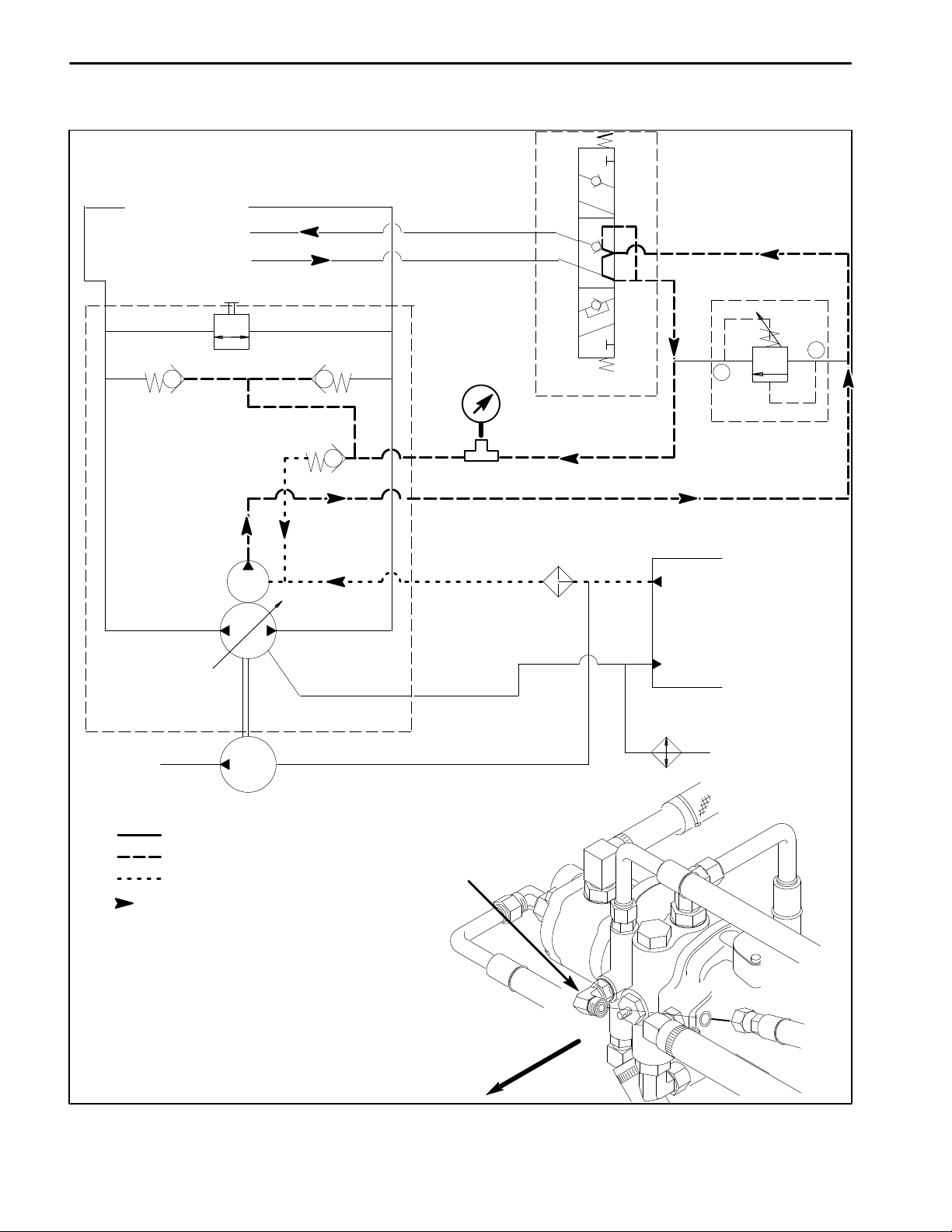
TEST NO. 3: Charge Pump Relief Pressure
TO WHEEL MOTORS
TO LIFT CYLINDER
FROM LIFT CYLINDER
BOTTOM
CHARGE PUMP
TRACTION PUMP
VALVE TOP
BOTTOM
FRONT
T–CONNECTION AND GAUGE
TOP
BOTTOM
IN (FRONT)
OUT (REAR)
2
1
CONTROL VALVE
IMPLEMENT RELIEF
FILTER
RESERVOIR
TO MANIFOLD
High Pressure
Low Pressure
Return or Suction
Flow
REEL MOTOR
DRIVE PUMP
FRONT
COOLER
RETURN FROM MANIFOLD
TO CHARGE
RELIEF
FRONT
Figure 14
Reelmaster 2300–D/2600–DHydraulic System Page 4 – 24
Page 63

Procedure for Charge Pump Relief
Check:
1. Make sure hydraulic oil is at normal operating temperature by operating the machine for approximately 10
minutes.
2. Make sure machine is parked on a level surface with
the cutting units lowered. Make sure engine is off and
the parking brake is engaged.
3. Make sure the hydraulic tank is full.
CAUTION
Operate all hydraulic controls to relieve
system pressure and avoid injury from
pressurized hydraulic oil.
4. Disconnect hose from the front fitting of the charge
pump leading to the control valve. Connect T–connector
and gauge to the pump and hose fitting.
CAUTION
Make sure that all hoses are free of the flywheel after installation.
5. Operate engine at full speed (3200 100 RPM).
6. Make sure hydraulic oil is at operating temperature.
7. Make sure that traction pedal and lift valve are in
neutral and the parking brake is engaged.
8. Pressure gauge should read from 100 to 150 PSI.
If Specification is not met, replace charge relief valve.
9. Shut off engine.
10. Disconnect gauge and T–connection from the
pump and hose. Reconnect hose to the pump.
System
Hydraulic
Reelmaster 2300–D/2600–D Hydraulic SystemPage 4 – 25
Page 64

TEST NO. 4: Reel Drive Pump Efficiency
TO CHARGE PUMP
FILTER
BOTTOM
RESERVOIR
FROM LEFT
WHEEL MOTOR
TO TRACTION PUMP
REEL DRIVE PUMP
P1
FC1
LC1
R1
S1
T2
HYDRAULIC MANIFOLD
FRONT
MD1
G1
M2
D1
M1
M5
D3
M6
M4
D2
M3
COOLER
RH
CTR
LH
High Pressure
Low Pressure
Return or Suction
Flow
2
3
TESTER
3
1
Figure 15
1. Hose fitting 2. Reel drive pump 3. O–ring
Reelmaster 2300–D/2600–DHydraulic System Page 4 – 26
Page 65

Procedure for Reel Drive Pump Efficiency
1. Make sure hydraulic oil is at normal operating temperature by operating the machine for approximately 10
minutes.
2. Make sure machine is parked on a level surface with
the cutting units lowered. Make sure engine is off and
the parking brake is engaged.
Check:
5. Install tester in series with reel drive pump and the
disconnected hose leading to port P1 of the hydraulic
manifold. Make sure the flow control valve is fully open.
6. Make sure backlap knob on the valve block is in the
mow position.
7. Make sure tester load valve is fully before starting
the engine.
3. Make sure the hydraulic tank is full.
CAUTION
Operate all hydraulic controls to relieve
system pressure and avoid injury from
pressurized hydraulic oil.
4. Clean hose connection and reel drive pump. Disconnect hose connection on the reel drive pump leading
port P1 on the hydraulic manifold.
IMPORT ANT: Make sure oil flow indicator arrow on
the flow gauge is showing that the oil will flow from
the pump through the tester and into the valve
block.
8. Start engine and move throttle to full speed (3200
100 RPM). Do not engage the cutting units.
9. Watch pressure gauge carefully while slowly clos-
ing the flow control valve until 1500 PSI is obtained.
Verify with a phototac that the pump speed is 2900 RPM.
10. Flow indication should be 5.4 GPM minimum.
11. Shut off engine.
12. Disconnect tester from manifold and hose. Recon-
nect hose to the pump.
13. If flow was less than 5.4 GPM or a pressure of 1500
PSI cannot be obtained, check for restriction in the pump
intake line. If line is not restricted, remove pump and repair or replace as necessary.
System
System
Hydraulic
Hydraulic
Reelmaster 2300–D/2600–D Hydraulic SystemPage 4 – 27
Page 66

TEST NO. 5: Manifold Relief Valve Pressure
G1
FROM REEL
DRIVE PUMP
TESTER
M2
FROM CARTRIDGE
VALVES AND LEFT
WHEEL MOTOR
SHUTTLE VALVE
MD1
HYDRAULIC MANIFOLD
D1
M1
M5
D3
M6
M4
D2
M3
RH
CTR
TO COOLER
LH
High Pressure
Low Pressure
Return or Suction
Flow
Install tester in series
between fitting and
hose at the motor (right
hand motor shown).
Figure 16
Reelmaster 2300–D/2600–DHydraulic System Page 4 – 28
Page 67

Procedure for Manifold Relief Valve Pressure
Check:
7. Start engine and move throttle to full speed (3200
100 RPM). Engage the cutting units.
1. Make sure hydraulic oil is at normal operating temperature by operating the machine for approximately 10
minutes.
2. Make sure machine is parked on a level surface with
the cutting units lowered. Make sure engine is off and
the parking brake is engaged.
3. Make sure the hydraulic tank is full.
CAUTION
Operate all hydraulic controls to relieve
system pressure and avoid injury from
pressurized hydraulic oil.
4. Clean hose connection and right hand reel motor.
Disconnect the hose leading from the right hand reel
motor to port M2 on the hydraulic manifold.
IMPORT ANT: Make sure oil flow indicator arrow on
the flow gauge is showing that the oil will flow from
the hose through the tester and into the motor.
5. Install tester in series with the hose and motor. Make
sure the flow control valve is fully open.
6. Make sure backlap knob on the valve block is in the
mow position. Make sure reel speed knob is set to position 9 or greater.
8. Watch pressure gauge carefully while slowly clos-
ing the flow control valve until the manifold relief opens.
9. System pressure should be from 2700 to 3300 PSI.
A. If specification is not met, adjust relief valve.
B. If this specification is met, go to step 11.
10. Adjusting the relief valve pressure as follows:
A. Remove the cap from the relief valve.
B. To increase the relief valve pressure set point,
use an allen wrench and turn set screw slightly
clockwise.
C. To decrease the relief valve pressure set point,
use an allen wrench and turn set screw slightly
counterclockwise.
D. Repeat steps 1 through 10 above until the relief
valve pressure set point is correct. Reinstall cap on
valve when valve is set properly.
E. If the relief valve pressure set point can not be
adjusted to specification, go to step 1 1 and replace
the relief valve.
11. Disengage cutting units. Shut off engine.
12. Disconnect tester from manifold and hose. Recon-
nect hose to the pump.
System
Hydraulic
CAUTION
Keep away from reels during test to prevent personal injury from the rotating reel
blades.
Reelmaster 2300–D/2600–D Hydraulic SystemPage 4 – 29
Page 68

TEST NO. 6: Cross–over Relief Pressures
TEST GAUGE
(TESTING IN MOW)
G1
FROM REEL
DRIVE PUMP
M2
FROM CARTRIDGE
VALVES AND LEFT
WHEEL MOTOR
MD1
D1
M1
M5
D3
M6
M4
D2
M3
RH
CTR
TO COOLER
LH
HYDRAULIC MANIFOLD
Figure 17
T–CONNECTION AND GAUGE
(TESTING IN BACKLAP)
High Pressure
Low Pressure
Return or Suction
Flow
Reelmaster 2300–D/2600–DHydraulic System Page 4 – 30
Page 69

Procedure for Cross–over Relief Pressures
1. Make sure hydraulic oil is at normal operating temperature by operating the machine for approximately 10
minutes. Make sure the hydraulic tank is full.
2. Make sure machine is parked on a level surface with
the cutting units lowered. Make sure engine is off and
parking brake is engaged. Back bedknives off all reels.
Check:
9. Remove test gauge and put cap on manifold port
G1.
IMPORTANT: Each reel motor has two cross over
reliefs. Test reliefs in the backlap direction only if
they are expected to be the problem. After testing
cross over reliefs in the backlap direction, make
sure the reel motor couplings are torqued (see Hydraulic Motor Removal and Installation of Chapter 7
– Cutting Units and Reel Motor in the Service and
Repair section).
CAUTION
Operate all hydraulic controls to relieve
system pressure and avoid injury from
pressurized hydraulic oil.
3. Clean manifold port G1. Remove cap and install
pressure gauge in manifold port G1.
4. Put a block of wood between the blades of the cutting unit being tested to prevent the reel from rotating.
5. Make sure backlap knob on the valve block is in the
mow position.
6. One person should sit on the seat and operate the
machine while another person reads the tester. Start engine and set throttle to full speed (3200 100 RPM).
CAUTION
Keep away from reels during test to prevent personal injury from the rotating reel
blades.
10. Clean left–hand reel motor and its hose connection
leading to manifold port M3. Disconnect hose connection and install pressure gauge with a T–connection between the hose connection and the motor.
1 1. Make sure backlap knob on the valve block is in the
backlap position.
12. One person should sit on the seat and operate the
machine while another person reads the gauge. Start
engine and move the throttle to full speed (3200 100
RPM).
CAUTION
Keep away from reels during test to prevent personal injury from the rotating reel
blades.
CAUTION
Do not allow system pressure to exceed
1700 PSI. Shut off unit to prevent an over
pressure condition.
System
Hydraulic
CAUTION
Do not allow system pressure to exceed
1700 PSI. Shut off unit to prevent an over
pressure condition.
7. Engage cutting units. Observe pressure gauge.
Motor Position
Right Hand 1500 to 1600
Rear 1540 to 1640
Left Hand 1580 to 1680
8. Disengage cutting units and stop engine. If specifications are not met, replace cross–over relief. If specifications are met, remove block of wood from cutting unit
and repeat test on other reels in mow direction.
Reelmaster 2300–D/2600–D Hydraulic SystemPage 4 – 31
Pressure Range (PSI)
13. Engage cutting units. Observe pressure gauge.
14. Disengage cutting units and stop engine. If specifi-
cations are not met, the cross–over relief needs replacing. Remove block of wood from cutting unit and repeat
test on other reels in the same direction of flow.
15. Remove test gauge and reconnect hose to motor.
Adjust bed bedknife to reel on all cutting units (see Adjustment section of Chapter 7 – Cutting Units.
Motor Position
Right Hand 1580 to 1680
Rear 1540 to 1640
Left Hand 1500 to 1600
Pressure Range (PSI)
Page 70

TEST NO. 7: Reel Motor Case Drain
R
MEASURE CASE DRAIN
FLOW HERE
G1
FROM REEL
MOTOR
DRIVE PUMP
TEST CONNECTION FOR
R.H. REEL MOTOR SHOWN
M2
FROM CARTRIDGE
VALVES AND LEFT
WHEEL MOTOR
MD1
HYDRAULIC MANIFOLD
D1
M1
M5
D3
M6
M4
D2
M3
RH
TESTER
TO COOLE
CTR
LH
High Pressure
Low Pressure
Return or Suction
Flow
Figure 18
Reelmaster 2300–D/2600–DHydraulic System Page 4 – 32
Page 71

Procedure for Reel Motor Case Drain
Check:
1. Make sure hydraulic oil is at normal operating temperature by operating the machine for approximately 10
minutes. Make sure the hydraulic tank is full.
2. Make sure machine is parked on a level surface with
the cutting units lowered. Make sure engine is off and
the parking brake is engaged.
CAUTION
Operate all hydraulic controls to relieve
system pressure and avoid injury from
pressurized hydraulic oil.
Motor
Position
Right Hand D1 M1
Left Hand D2 M3
Rear D3 M6
3. On suspected bad motor, clean hose connection
and disconnect hose from motor that returns to the manifold (see table).
IMPORT ANT: Make sure oil flow indicator arrow on
the flow gauge is showing that the oil will flow from
the motor through the tester and into the hose.
Manifold Port
(Case Drain)
Manifold Port
(Motor Return)
CAUTION
Keep away from reels during test to prevent personal injury from the rotating reel
blades.
7. Engage reels by pulling the knob on the instrument
panel out. While watching pressure gauges, slowly
close flow control valve until a pressure of 1200 PSI is
obtained.
8. Disengage cutting units and stop engine.
9. Clean hose fitting and disconnect hose from case
drain on the manifold block (see table). Plug the manifold port.
10. Put case drain hose into 1 quart container gra-
duated in ounces (1 liter container graduated in milliliters).
11. One person should sit on the seat and operate the
machine while another person holds the hose and reads
the tester. Start engine and move the throttle to full
speed (3200 100 RPM).
12. While sitting on seat, engage cutting units by pulling
the knob on the instrument panel out. Make sure gauge
pressure still reads 1200 PSI. After 15 seconds, push
knob on the instrument panel in to disengage cutting
units. Stop the engine.
System
Hydraulic
4. Install tester in series with the motor and the disconnected return hose. Make sure the flow control valve is
fully open.
5. Make sure backlap knob on the valve block is in the
mow position.
6. One person should sit on the seat and operate the
machine while another person reads the tester. Start engine and move the throttle to full speed (3200 100
RPM).
13. Measure the amount of oil collected in the container.
Divide the number of ounces collected by 32 to get gallons per minute. (Divide the number of milliliters collected by 250 to get liters per minute).
14. Disconnect tester from motor and hose. Reconnect
hose to the pump.
15. Remove cap from manifold fitting. Reconnect case
drain hose to the motor.
16. If flow was greater than 0.7 GPM (2.6 LPM), repair
or replace the reel motor as necessary.
Reelmaster 2300–D/2600–D Hydraulic SystemPage 4 – 33
Page 72

Adjustments
Transmission for Neutral
If the machine “creeps” when the traction control pedal
is in the neutral position, the neutral return mechanism
must be adjusted.
1. Block up under the frame so one of the front wheels
is off the floor . Place selector control in two wheel drive
position.
2. Start engine, move throttle to SLOW and check front
wheel that is off shop floor; it must not be rotating. Loosen pump plate nuts and rotate pump plate until creep
does not occur in either direction. When wheel stops rotating, tighten nuts locking adjustment. Verify the adjustment with throttle in SLOW and FAST position.
3. Should the wheel continue to rotate, check for the
following:
A. Ball bearing is loose or worn out.
1
2
B. Loose or missing fasteners.
C. Worn fasteners.
D. Pump lever loose on control shaft.
E. Weak or damaged Ieaf springs. Replace.
F. Internal pump component malfunction.
4. After adjusting the pump plate, check neutral switch
operation and if necessary, adjust as follows:
A. Loosen locknut securing switch adjusting screw.
Thread away from switch until capscrew head
clears switch.
B. Rotate adjusting screw toward switch until circuit
through switch is made. Then, turn adjusting screw
an additional 2–1/2 turns.
C. Tighten locknut
5
1. Pump plate nut
2. Pump
3. Neutral switch
4
3
Figure 19
4. Adjusting screw
5. Lock nut
Reelmaster 2300–D/2600–DHydraulic System Page 4 – 34
Page 73

Traction Pedal
If traction pedal stop cam contacts the footrest when
pushed fully forward or maximum forward traction
speed is unattainable, an adjustment to the traction pedal linkage is required.
1. To expose traction rod, remove screws securing
right fender to frame and remove fender.
2
2. Loosen jam nuts on each end of traction rod.
3. Rotate rod until pedal stop cam clearance is from
0.03 to 0.09 inch (0.8 to 2.3 mm) with the pedal depressed.
4. Retighten jam nuts securing traction rod adjustment.
IMPORTANT: Verify reverse speed with one front
wheel off the ground in 2WD and the engine at high
idle. Reverse wheel speed should be from 120 to 140
RPM. Damage may result to rear motor if this speed
is exceeded.
5. The stop for reverse travel (under pedal) may be adjusted for slower travel.
4
3
1
1. Traction rod
2. Damper
3. Damper pivot
PEDAL ST OP CAM
5
Figure 20
4. Damper bracket
5. Pedal cam stop
0.03 to 0.09 in.
(0.8 to 2.3 mm)
System
Hydraulic
Traction Pedal Damper (Fig. 20)
1. T o expose traction pedal damper, remove right hand
panel.
2. Loosen locknut securing damper pivot to the damper bracket.
3. Depress traction pedal fully forward and hold.
Reelmaster 2300–D/2600–D Hydraulic SystemPage 4 – 35
4. Fully compress damper and then release it allowing
it to extend 0.08 inch (2.0 mm). Tighten locknut securing
the damper pivot to the damper bracket.
5. When traction pedal is fully depressed in reverse
direction, traction pedal must contact reverse stop so
the damper does not act as the stop in either direction.
FOOT PLATE
Figure 21
Page 74

Hydraulic Pump Drive Belt
Make sure pump belt is properly tensioned to assure
proper operation of the machine and prevent unnecessary wear. On new belts, check tension after 8 hours operation.
A new hydraulic pump belt should tensioned so it deflects 0.120 inch with a 15 to 17 pound load applied midway in span of belt. A used belt should tensioned so that
it deflects 0.120 inch with a 1 1 to 13 pound load applied
midway in span of belt.
2
Note: Tighten belt to eliminate slippage (squealing
under load) but do not overtighten.
1. Tighten nut on adjustment rod until desired belt tension is attained.
1
1
Figure 22
1. Nut 2. Adjustment rod
Reelmaster 2300–D/2600–DHydraulic System Page 4 – 36
Page 75

Service and Repairs
Traction/Charge Pump
15
10
1
13
16
11
14
34
17
35
32
33
4
37
22
31
34
3
2
9
36
27
13
38
24
30
34
34
8
21
7
5
35
26
System
Hydraulic
1. Cap screw
2. Reel motor drive pump
3. O–ring
4. Traction/charge pump
5. Hose
6. Hose
7. Hydraulic fitting
8. Hydraulic fitting
9. Hose connection
10. Hose connection
11. Hose connection
12. Hose connection
13. O–ring
14. O–ring
15. Hydraulic fitting
17
20
19
18
16. Hydraulic fitting
17. Hydraulic fitting
18. Cap screw
19. Flat washer
20. Pump lever assembly
21. Lock nut
22. Pump mount
23. Cotter pin
24. Clevis pin
25. Belt adjustment yoke
26. Pump drive belt
27. Pulley
28. Cap screw
29. Lock washer
25
12
14
39
42
Figure 23
40
43
23
29
28
41
30. T apered lock bushing
31. Cap screw
32. Lock nut
33. Washer
34. O–ring
35. O–ring
36. Set screw
37. Key
38. Key
39. Lock nut
40. Cap screw
41. Pump control rod
42. Spacer
43. Nut
Reelmaster 2300–D/2600–D Hydraulic SystemPage 4 – 37
Page 76

Removal (Fig. 23)
Installation (Fig. 23)
1. Before removing any parts, park the machine on a
level surface, engage parking brake, lower cutting units
and stop engine. Remove key from the ignition switch.
CAUTION
Operate all hydraulic controls to relieve system
pressure and avoid injury from pressurized hydraulic oil.
2. Clean pump assembly and hydraulic connections.
Label all hose connections for reassembly purposes.
Put caps or plugs on any hydraulic lines or fittings left
open or exposed. Install plug into the hydraulic reservoir.
3. Remove both cap screws (1) from the pump assembly . Carefully separate the reel motor drive pump (2) and
O–ring (3) from the traction/charge pump (4). Position
reel motor drive pump away from traction/charge pump.
4. Remove hoses (5 and 6) from hydraulic fittings (7
and 8). Remove hose connections (9, 10, 11, and 12)
from hydraulic fittings (15, 16, and 17). Allow hoses to
drain to a suitable container.
5. Remove cap screw (40) and lock nut (39) from the
pump control rod (41), spacer (42), and pump lever assembly (20).
6. Loosen lock nut (21) at the pump mount (22) and nut
(43) at the belt adjustment yoke (25). Remove cotter pin
(23) and clevis pin (24) from the belt adjustment yoke.
7. Tilt pump mount (22) and remove pump drive belt
(26) from the pulley (27).
8. Remove cap screws (28) and lock washers (29)
from the pulley (27) and taper lock bushing (30). Run
cap screws into tapped holes in the pulley, then drive
pulley off the taper lock bushing.
9. Support traction/charge pump (4). Remove both
cap screws (31), lock nuts (32), and washers (33) from
the traction/charge pump and pump mount (22). Separate traction/charge pump from the pump mount.
1. Mount the traction/charge pump (4) to the pump
mount (22). Place both cap screws (31) through the
pump mount and pump base. Install washers (33) and
lock nuts (32) onto cap screws. Tighten cap screws.
2. Place key (37) in the keyway on the pump shaft.
Slide taper lock bushing (30) into place on the pump
shaft. Tighten set screw (36).
3. Insert cap screws (28) through washers (29) and
pulley (27). Install pulley to taper lock bushing (30). Start
cap screws into bushing and leave cap screws loose.
4. Loosen set screw (36) and adjust pulley (27) so the
gap between the pulley and pump mount is 0.20 inch.
Evenly torque cap screws from 90 to 120 in–lb. (104 to
138 kg–cm) three times each. Readjust as required.
5. Make sure mounting and O–ring sealing surfaces
on reel motor drive pump (2) and traction/charge pump
(4) are clean.
6. Inspect O–ring (3) and replace if damaged or worn.
Apply clean hydraulic oil to O–ring. Place O–ring on reel
motor drive pump (2).
7. Position reel motor drive pump (1) to traction/charge
pump (4). Secure reel motor drive pump to traction/
charge pump with cap screws (1).
8. Coat all O–rings with clean hydraulic oil. Install hydraulic fittings (7, 8, 15, and 16) and O–rings (34) into the
traction/charge pump (4). Torque these fittings from 23
to 27 ft–lb and as close to their original position.
9. Coat all O–rings with clean hydraulic oil. Install hydraulic fittings (17) and O–rings (35) into the traction/
charge pump (4). Tighten these fittings as close to their
original position as possible.
10. Connect hoses (5 and 6) to hydraulic fittings (7 and
8); tighten both hose clamps. Connect hose connections (9, 10, 1 1, and 12) to hydraulic fittings (15, 16, and
17). Tighten all hose connections.
11. Replace cap screw (40) through the pump control
rod (41), spacer (42) and pump lever assembly (20). Secure lock nut (39) to the capscrew and tighten.
Note: Steps 10 and 11 may be performed depending
on the extent of the pump repair.
10. Remove fittings (7, 8, 15, 16, and 17) and O–rings
(34 and 35) from the traction/charge pump (4).
11. Unscrew set screw (36) enough to loosen tapered
lock bushing (30). Slide tapered lock bushing off the
pump shaft. Remove key (37) from pump shaft.
12. Install pump drive belt (26) onto pulley (27). Align
the holes of the mounting plate (22) with the holes of the
belt adjustment yoke (25) and slide clevis pin (24)
through holes. Secure clevis pin with the cotter pin (23).
13. Adjust pump drive belt (see Adjustments section)
Tighten lock nut (21) and torque from 60 to 70 ft–lb (8.3
to 9.7 kg–m).
14. Remove plug from the hydraulic reservoir.
Reelmaster 2300–D/2600–DHydraulic System Page 4 – 38
Page 77

78
9
10
11
12
13
14
5
38
15
6
39
4
3
13
2
1
18
19
11
17
16
7
20
27
28
1. Cap screw
2. Charge pump adapter assembly
3. Gerotor assembly
4. Bearing
5. Valve assembly
6. Valve plate
7. Screw
8. Trunnion cover
9. O–ring cover
10. O–ring
11. Washer
12. Inner race
13. Bearing
14. Bearing
KEY
COUPLER
OUTER RING
INNER RING
26
Figure 24
15. Housing assembly
16. Seal cover
17. Shaft seal
18. Dowel pin
19. Key
20. Camplate
21. Plug
22. Spring
23. Seat
24. Gasket
25. Backplate assembly
26. O–ring
27. Cap screw
25
18
24
23
22
40
21
30
31
28. Bearing
29. Rotating parts kit
30. Key
31. Drive shaft
32. Retaining ring
33. Bearing race
34. Thrust bearing
35. Washer
36. Shaft seal
37. Retaining ring
38. O–ring
39. O–ring
40. O–ring
29
32
33
34
33
32
35
37
36
System
Hydraulic
Disassembly (Fig. 24)
4. Remove outer ring from either the inner ring of the
gerotor assembly (3) or the charge pump adapter as-
1. Position pump into a vise with protected jaws so the
charge pump drive shaft is pointed up. Clamp onto the
sembly (2). Further disassembly of the gerotor assembly is not necessary.
mounting flange of the traction pump.
2. Remove cap screws (1 and 27) and slide charge
pump adapter assembly (2) from the backplate assembly (25) clear of the shaft (31) and gerotor assembly (3).
3. Remove O–ring (26) from the charge pump adapter
assembly (2).
Reelmaster 2300–D/2600–D Hydraulic SystemPage 4 – 39
Page 78

5. The charge pump adapter assembly (2) can be disassembled as follows (see Fig. 25):
A. Unscrew and remove spring retainer from the
charge pump adapter assembly.
B. Remove spring and cup poppet from the charge
pump adapter assembly.
SPRING RETAINER
SPRING
CUP POPPET
6. Remove gerotor assembly (3) inner ring and coupler from the shaft (31).
7. Lift backplate assembly (25) up and off from the
shaft (31) and housing assembly (15). Remove valve
plate (6) from the backplate assembly or rotating parts
kit (29).
8. Remove valve assembly (5) and O–rings (38 and
39) from the backplate assembly (25). Disassembly of
the valve assembly is not necessary.
9. Remove both plugs (21), O–rings (40), spring (22),
and seats (23) from the backplate assembly (25).
10. Remove gasket (24) from the housing (15) or backplate assembly (25).
Note: To remove the rotating parts kit (29) from the
shaft (31), a table or workbench with a hole in the working surface is required for the protruding shaft.
1 1. The rotating parts kit (29) can be removed from the
shaft (31) as follows:
A. Hold rotating parts kit (29) in place and remove
the pump from the vise.
B. Position the housing assembly (15) end of the
pump up and lower the shaft (31) through the hole in
the table or workbench. Allow rotating parts kit (29)
to rest on the table.
C. Remove rotating parts kit (29) by lifting away the
housing assembly (15) and shaft (31).
12. The rotating parts kit (29) can be disassembled as
follows (see Fig. 26):
A. Remove nine piston assemblies, spider, and spider pivot from the piston block.
SUCTION PORT
BEARING
CHARGE PUMP
ADAPTER ASSEMBLY
Figure 25
VALVE PLATE END
WASHER
SPRING
PINS
RETAINER
SPIDER
CAMPLATE END
WASHER
RETAINING RING
PISTON BLOCK
SPIDER PIVOT
PISTON ASSEMBLIES
Figure 26
B. Use the following parts to disassemble the piston block:
2 5/16 in. I.D. 15/16 in. O.D. flat washers
1 5/16 in. 2–7/8 in. N.C. cap screw
1 5/16 in. N.C. nut
C. Place cap screw through one of the flat washers.
Insert cap screw through the center of the piston
block. Install second flat washer onto the capscrew
so the washer rests on the three pins. Screw nut
onto the cap screw.
CAUTION
Be careful when removing the spring
from the piston block; the spring is highly
compressed. Safely compress the spring
before removing the retaining ring.
D. Compress spring by tightening the nut onto the
cap screw. Remove the retaining ring from the piston block.
E. Slide washer, spring, second washer , three pins,
and retainer from the piston block.
Reelmaster 2300–D/2600–DHydraulic System Page 4 – 40
Page 79

13. Remove retaining ring (37) from the bore on the
flange end of the housing assembly (15). Press the shaft
(31), shaft seal (36), and washer (35) from the housing
assembly .
14. Remove retaining ring (32), washer (35), thrust
bearing (34), second washer (35), and second retaining
ring (32) from the shaft (31).
15. Remove screws (7), trunnion cover (8), O–ring cover (9), O–ring (10), washer (11), inner race (12), and
bearing (13). Remove screws (7), seal cover (16), shaft
seal (17), washer (11), and bearing (13).
16. Position camplate (20) to one side and remove from
the housing assembly (15).
Inspection
FLANGE
GEROTOR POCKET
0.070 to 0.080 in.
(1.78 to 2.03 mm)
Figure 27
0.090 to 0.100 in.
(2.54 to 2.89 mm)
BEARING
DEPTH
0.105 to 0.115 in.
(2.67 to 2.92 mm)
CAUTION
Use eye protection such as goggles when
using compressed air
1. Wash all parts in solvent. Dry parts with compressed
air.
2. Inspect charge pump adapter assembly (see Fig.
25).
A. Check relief valve seat inside suction port. Make
sure that seat is smooth and free of burrs or other
defects. Relief valve spring must not be damaged.
B. Bearing needles must remain in bearing cage
and move freely. Verify that bearing depth on the
flange side meets the dimension in Figure 27.
C. Make sure gerotor pocket inside the pump is not
excessively scored.
3. Inspect backplate assembly (25) (see Fig. 24).
A. Bearing needles must remain in bearing cage
and move freely. Verify that bearing height on the
numbered end meets the dimension in Figure 28.
BEARING
HEIGHT
ROLL PIN
HEIGHT
Figure 28
FLANGE END OF HOUSING
0.062 to 0.078 in.
(1.57 to 1.98 mm)
BEARING
DEPTH
NUMBERED END
Figure 29
5. Inspect housing assembly (15) (see Fig. 24).
A. Verify that bearing depth on the numbered end
meets the dimension in Figure 29.
System
System
Hydraulic
Hydraulic
B. Check that the roll pin is tight and meets the
height in Figure 28.
C. Replace entire assembly as a unit.
4. Inspect camplate assembly (20) (see Fig. 24).
There should be no signs of scoring on the piston shoe
surfaces.
Reelmaster 2300–D/2600–D Hydraulic SystemPage 4 – 41
B. Bearing needles must move freely and remain in
their cage.
Page 80

6. Inspect rotating parts kit (see Fig. 26).
9. Reassemble rotating parts kit as follows (Fig. 26):
A. Verify that piston O.D. finish shows no wear or
deep scratches. Piston shoes should fit snuggly
onto the ball end of the pistons. The shoe surface
that contacts the camplate should be smooth and
flat. Do not lap piston shoes.
B. Examine the mutual contact surfaces on the spider and spider pivot; both contact areas should be
smooth and free of wear.
C. The piston block surface that makes contact with
the valve plate should be smooth and free of deep
scratches. Do not lap piston shoes.
D. The bore areas of the piston block should be free
of scoring and contamination. Pistons should move
freely in the bore areas.
Reassembly (Fig. 24)
1. Make sure all parts are clean. Lubricate all critical
moving parts and O–rings with clean hydraulic oil.
2. If necessary, press new bearing (14) into housing
assembly (15) to the dimension shown in Figure 29.
3. Insert camplate (20) into the housing assembly (15).
A. Use the following parts to reassemble the piston
block:
2 5/16 in. I.D. 15/16 in. O.D. flat washers
1 5/16 in. 2–7/8 in. N.C. cap screw
1 5/16 in. N.C. nut
B. Compress retainer and install into the spline of
the piston block.
C. Position the head end of pins towards the inside
of the block. Install the three pins into the special
grooves in the piston block.
D. Install a washer, spring, and second washer into
the piston block.
E. Place cap screw through one of the flat washers.
Insert cap screw through the center of the piston
block. Install second flat washer onto the capscrew
so the washer rests on the three pins. Screw nut
onto the cap screw.
F. Compress spring by tightening the nut onto the
cap screw. Install the retaining ring into the piston
block.
4. On the short trunnion side of the camplate (20),
install bearing (13) with numbered side to the inside of
the pump. Install inner race (12) with the chamfer towards the inside of the pump. Install washer (1 1), O–ring
(10), O–ring cover (9), and trunnion cover (8). Secure
trunnion cover with two screws (7) torque them from 36
to 48 in–lb (42 to 55 kg–cm).
5. On the long trunnion side of the camplate (20),
install bearing (13) with numbered side to the inside of
the pump. Install washer (1 1) and press shaft seal (17)
into place. Secure seal cover( 16) with two screws (7)
and torque them from 36 to 48 in–lb (42 to 55 kg–cm).
6. Install retaining ring (32) towards the keyed end of
the shaft (31). Slide washer (33), thrust bearing (34), second washer (33), and second retaining ring (32) into
place over the splined end of the shaft.
7. Position washer (35) and shaft seal (36) onto the
shaft (31) from the keyed end.
8. Install shaft (31) into the housing assembly (15)
from the flanged end. Press shaft seal (36) into position
with a seal driver. Install retaining ring (37) into the
flanged end of the housing assembly (15).
G. Unscrew the nut and remove washer and cap
screw from the piston block.
H. Install spider pivot onto the three pins and place
the spider on the spider pivot.
I. Insert piston assemblies through the spider and
into the piston block with the piston shoes resting on
the spider.
10. Set rotating kit assembly (29) on a working surface
with the piston shoes facing up. Insert shaft (31) through
the rotating kit assembly with the flanged end of the
housing assembly up. Position rotating kit assembly into
the housing assembly.
11. Make sure piston block and shaft (31) splines are
aligned. Make sure piston block is engaged fully so the
piston shoes are in contact with the camplate (20). Make
sure all parts are in their proper position be for proceeding to the next step.
12. Hold rotating kit assembly (29) in place, and clamp
housing assembly (15) with the flange end down into a
vise with protected jaws. Install gasket (24) and two
dowel pins (18) into the housing assembly (15).
13. If necessary, press new bearing (4) or roll pin into
backplate assembly (25) to the dimension shown in Figure 28. Bearing should be installed with numbered end
outward. Roll pin should be installed with split oriented
away from the bearing.
Reelmaster 2300–D/2600–DHydraulic System Page 4 – 42
Page 81

14. Install seat (23) and spring (22) into backplate (25).
Install new O–ring (40) and plug (21) into the backplate
assembly . T orque plug from 95 to 105 ft–lb (13.1 to 14.5
kg–m).
15. Install new O–rings (38 and 39) and valve assembly
(5) into the backplate assembly (25). Torque valve assembly from 27 to 30 ft–lb (3.7 to 4.1 kg–m).
19. Reassemble charge pump adapter assembly (2) as
follows (see Fig. 25):
A. Install cup poppet, spring, and spring retainer
into the charge pump adapter assembly.
B. Torque retainer from 5 to 7 ft–lb (0.7 to 1.0
kg–m).
16. Coat valve plate (6) with light coat of petroleum jelly
on the steel side. Align the valve plate to the roll pin on
the backplate (25). Install steel side of the valve plate to
the backplate.
17. Install backplate assembly (25) to the housing assembly (15). Make sure gasket (24), valve plate (6), and
dowel pins (18) stay in place.
18. Install inner ring and coupler of gerotor assembly (3)
into the backplate assemble (25) so that the V–groove
on the coupler end enters the backplate assembly first.
Lubricate the inner ring of the gerotor.
20. Coat O–ring (26) and outer ring of gerotor assembly
(3) with a light coat of petroleum jelly . Install O–ring and
outer ring onto the charge pump adapter assembly (2).
Install charge pump adapter plate onto the backplate assembly (25). Make sure O–ring and outer ring of gerotor
assembly stay in place.
21. Secure charge pump adapter assembly (2) and
backplate assembly (25) to the housing assembly (15)
with cap screws (1 and 27). Torque cap screws from 17
to 20 ft–lb ( 2.3 to 22.8 kg–m).
System
Hydraulic
Reelmaster 2300–D/2600–D Hydraulic SystemPage 4 – 43
Page 82
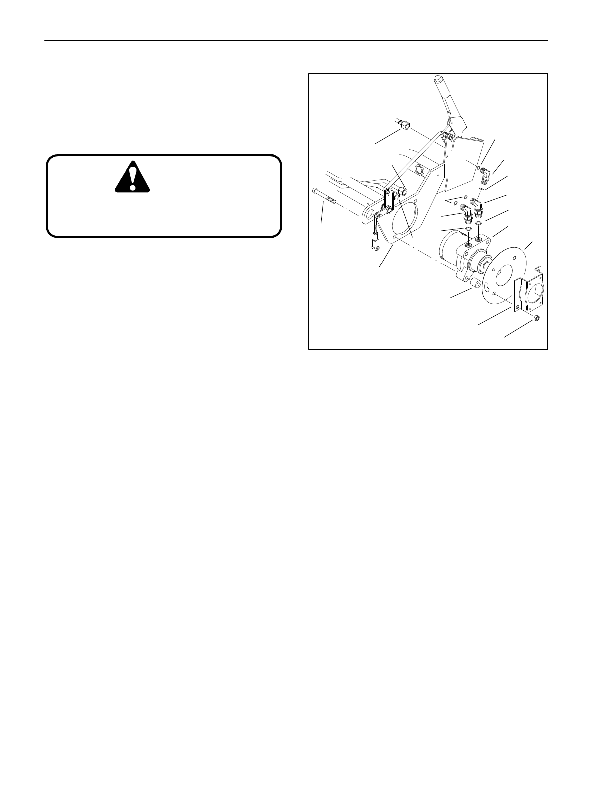
Wheel Motor
Front Wheel Removal (Fig. 30)
1. Before removing any parts from the hydraulic system, park the machine on a level surface, engage the
parking brake, lower the cutting units and stop the engine. Remove the key from the ignition switch.
CAUTION
Operate all hydraulic controls to relieve
system pressure and avoid injury from
pressurized hydraulic oil.
2. Remove wheel and brake assembly from unit (see
Repair section of Chapter 6 – Wheels and Brakes).
10
9 (LH)
4
3
7 (LH)
17 (LH)
6
8
16
5
16
2
1
14
12
3. Clean wheel motor (1) and hydraulic connections.
Label all tube hose connections for reassembly purposes. Put caps or plugs on any hydraulic lines or fittings
left open or exposed.
4. Disconnect tube connections (2 and 3) from hydraulic fittings (5 and 6). On the left–hand wheel motor, also
disconnect hose connection (4) from hydraulic fitting (7).
Allow hydraulic oil to drain from tubes and hose into a
suitable container.
5. Support wheel motor (1). Remove four cap screws
(10) and lock nuts (1 1) from support frame (12). Remove
brake bracket (13), grass shield (14), and spacers (15).
Pull wheel motor from the support frame.
6. Remove hydraulic fittings (5 and 6) and O–ring from
the wheel motor (1). On the left–hand wheel motor, also
remove hydraulic fitting (7) from the wheel motor.
Front Wheel Installation (Fig. 30)
1. Place and support wheel motor (1) into the support
frame (12). Insert four cap screws (10) through the support frame and wheel motor.
15
13
11
Figure 30
1. Wheel motor
2. Tube connection
3. Tube connection
4. Hose connection
5. Hydraulic fitting
6. Hydraulic fitting
7. Hydraulic fitting
8. O–ring
9. O–ring
10. Cap screw
11. Lock nut
12. Support frame
13. Brake bracket
14. Grass shield
15. Spacer
16. O–ring
17. O–ring
4. Install tube connections (2 and 3) to hydraulic fittings (5 and 6). On the left–hand motor, also ins hose
connection (4) to hydraulic fitting (7). Tighten connections.
5. Install wheel and brake to unit (see Repair section
of Chapter 6 – Wheels and Brakes).
2. Slide spacers (15), grass shield (14), and brake
bracket (13) onto the cap screws (10) and wheel motor
(1). Tighten lock nuts (11) onto cap screws.
3. Install hydraulic fittings (5 and 6) onto the wheel motor (1). On the left–hand wheel motor, also install hydraulic fitting (7) onto the wheel motor. T ighten hydraulic
fittings.
Reelmaster 2300–D/2600–DHydraulic System Page 4 – 44
Page 83

3WD Rear Wheel Removal (Fig. 31)
1. Before removing any parts from the hydraulic system, park the machine on a level surface, engage the
parking brake, lower the cutting units and stop the engine. Remove the key from the ignition switch.
CAUTION
7
1
Operate all hydraulic controls to relieve
system pressure and avoid injury from
pressurized hydraulic oil.
2. Clean wheel motor (1) and hydraulic connection.
Put caps or plugs on any hydraulic lines or fittings left
open or exposed.
3. Remove wheel and wheel hub from unit (see Repair
section of Chapter 6 – Wheels and Brakes).
4. Disconnect hose connection (2) from hydraulic fittings (3). Remove O–ring (4). Allow hydraulic oil to drain
from the hose into a suitable container.
5. Support wheel motor (1). Remove four cap screws
(5) and lock nuts (6) from the rear wheel fork (7). Pull
wheel motor from the rear wheel fork.
6. Remove hydraulic fitting (3) and O–ring (8) from the
wheel motor (1).
Rear Wheel Installation (Fig. 31)
5
1. Wheel motor
2. Hose connection
3. Hydraulic fitting
4. O–ring
6
Figure 31
8
5. Cap screw
6. Lock nut
7. Rear wheel fork
8. O–ring
2
4
3
System
Hydraulic
1. Place and support wheel motor (1) into the rear
wheel fork (7). Insert four cap screws (5) through the
rear wheel fork and wheel motor.
2. Tighten lock nuts (6) onto cap screws (5).
3. Install hydraulic fitting (3) and O–ring (8) onto the
wheel motor (1). Tighten hydraulic fitting.
4. Install O–ring (4) while connecting hose connections (2) onto the hydraulic fitting (8). Tighten connection.
5. Install wheel and wheel hub to unit (see Repair section of Chapter 6 – Wheels and Brakes).
Reelmaster 2300–D/2600–D Hydraulic SystemPage 4 – 45
Page 84

11
12
13
10
8
9
8
7
6
3
2
1
5
4
15
17
16
14
24*
SHUTTLE
VALVE
24
24*(PLUG)
25*
PLUG
25*
SPRING
23
24*
(PLUG)
20
21
22
*LEFT HAND MOTOR ONLY
19
Figure 32
1. Dirt and water seal
2. Outer bearing
3. Housing
4. Backup washer
5. Seal ring
6. Backup washer
7. Inner seal
8. Thrust washer
9. Thrust bearing
10. Inner bearing
11. Coupling shaft
12. Thrust bearing
13. Drive link
14. Cap screw
15. Commutator seal
16. Commutator
17. Woodruff key
Disassembly (Fig. 32)
W ARNING
If the wheel motor is not held firmly in the
vise, it could dislodge during service and
cause injury.
1. Place wheel motor in a soft jawed vice with the coupling shaft (1 1) pointed down and the vise jaws clamping
firmly on the sides of the housing (3).
18
18. Wear plate
19. Rotor
20. Vane
21. Stator
22. Manifold
23. Commutator ring
24. End cover assembly
25. O–ring
2. Scribe an alignment mark down and across the
wheel motor components from the end cover (24) to the
housing (3) for facilitating reassembly (Fig. 33). If included in end cover, loosen both shuttle valve plugs
(left–hand motor only) for disassembly later.
Figure 33
3. Remove seven cap screws (14). Remove end cover
assembly (24) and seal ring (5).
Reelmaster 2300–D/2600–DHydraulic System Page 4 – 46
Page 85

Note: Be ready to catch the shuttle valve or relief valve
components that will fall out of the end cover valve cavity
when the plugs are removed.
Note: O–ring (25) is not included in the seal kit, but
can be serviced separately if required.
Note: The insert and ,if included, the orifice plug in the
end cover assembly (24) must not be removed as they
are serviced as an integral part of the end cover.
4. If the end cover (24) is equipped with shuttle valve
components (left–hand motor only), remove both previously loosened plugs and O–rings (25).
5. Remove commutator ring (23).
CAUTION
Use eye protection such as goggles when
using compressed air
6. Remove commutator (16) and commutator seal
(15). Remove commutator seal from the commutator
using an air hose to blow air into the ring groove until the
commutator seal is lifted out (Fig. 34)
Note: The manifold (22) is constructed of plates
bonded together to form an integral component not subject to further disassembly for service. Compare configuration of both sides of the manifold to make sure that
same surface is reassembled against the rotor set.
7. Remove manifold (22). Remove seal rings (5) that
are on both sides of the manifold.
Note: The rotor set consists of the rotor (19), vanes
(20), and stator (21). Rotor set components may become disassembled during service procedures.
Note: Marking all rotor components and mating spline
components for exact repositioning at assembly will
make sure maximum wear life and performance of rotor
set and wheel motor.
8. Mark surface of rotor (19) and stator (21) that is facing up with etching ink or a grease pencil before removing from the wheel motor. This will make sure correct
reassembly of the rotor into the stator and the rotor set
into wheel motor.
9. Remove rotor set and wearplate (18) together, and
retain the rotor set in its assembled form with the same
vane (20) to stator (21) contact surfaces. The drive link
(13) may come away from the coupling shaft (11) with
the rotor set and wearplate. Y ou may have to shift the rotor set on the wearplate to work the drive link out of the
rotor (19) and wearplate (Fig. 35).
Figure 34
Figure 35
10. Remove seal ring (5) that is between the rotor set
and wearplate.
1 1. Remove drive link (13) from the coupling shaft (11)
if it was not removed with rotor set and wear plate (18).
Remove seal ring (5) from housing (3).
12. Remove thrust bearing (12) from the top of the cou-
pling shaft (11).
13. Check exposed portion of coupling shaft (11) to be
sure you have removed all signs of rust and corrosion
which might prevent its withdrawal through the dirt and
water seal (1) and outer bearing (2). Crocus cloth or fine
emery paper may be used.
14. Remove coupling shaft (1 1); push on the output end
of the shaft. Remove seal ring (5) from housing (3).
15. Remove housing (3) from the vise and invert it. Re-
move dirt and water seal (1). A blind hole bearing or seal
puller is required.
System
Hydraulic
Reelmaster 2300–D/2600–D Hydraulic SystemPage 4 – 47
Page 86

Inspection (Fig. 32)
1. Inspect bolts (14) for damaged threads and sealing
rings under the bolt head. Replace if damaged (Fig. 36).
Note: A polished pattern (not scratches) on the cover
from rotation of the commutator (16) is normal. Discoloration would indicate excess fluid temperature, thermal
shock, or excess speed and require system investigation for cause and close inspection of end cover, commutator, manifold, and rotor set.
CAUTION
Use eye protection such as goggles when
using compressed air
2. Thoroughly wash end cover (24) in proper solvent
and blow dry . Make sure the end cover valve apertures,
including the internal orifice plug, are free of contamination. Inspect end cover for cracks and the bolt head recesses for good bolt head sealing surfaces. Replace
end cover as necessary (Fig. 37).
3. Inspect commutator ring (23) for cracks and burrs.
Replace commutator ring as necessary.
4. Inspect commutator (16) for cracks, burrs, wear,
scoring, chipping, and peening. If any of these conditions exist, replace commutator and commutator ring
(23) as a matched set.
5. Inspect manifold (22) for cracks, surface scoring,
peening, chipping. Replace manifold if any of these
conditions exist. A polished pattern on the ground surface from commutator or rotor rotation is normal.
Figure 36
Figure 37
Note: The rotor set consists of the rotor (19), vanes
(20), and stator (21). Rotor set components may become disassembled during service procedures.
6. Inspect the rotor set in its assembled form for nicks,
scoring, and chipping on any surface. Inspect for broken
and worn splines. If the rotor set component requires replacement, the complete rotor set must be replaced as
it is a matched set.
7. Place rotor set and wear plate (18) on a flat surface
and center the rotor (19) in the stator (21) such that two
rotor lobes (180 degrees apart) and a roller vane (20)
center line are on the same stator center line. Check the
rotor lobe to roller vane clearance with a feeler gage at
this common center line. If there is more than 0.005 inch
(0.13 mm) of clearance, replace the entire rotor set (Fig.
38).
Figure 38
Figure 39
Reelmaster 2300–D/2600–DHydraulic System Page 4 – 48
Page 87

8. Inspect the wearplate (18) for cracks, peening, and
scoring. A polished pattern on the wear plate from rotor
rotation is normal. Replace as necessary.
9. Inspect drive link (13) for cracks and worn or damaged splines. No perceptible lash (play) should be noted
between mating spline parts of the rotor (19) or coupling
shaft (11). Replace as necessary (Fig. 39).
10. Inspect thrust bearing (12) for wear, peening, corrosion and a full complement of retained rollers. Replace
as necessary.
11. Inspect coupling shaft (11) internal and external
splines and keyway for damage and wear. Inspect bearing and sealing surfaces of the coupling shaft for chipping, nicks, grooves, severe wear, corrosion, and
discoloration. Replace coupling shaft if any of these
conditions exist. Minor shaft wear in seal area is permissible. If wear exceeds 0.020 inch (0.51 mm) diametrically , replace coupling shaft. A slight ”polish” is permissible
on the shaft bearing areas (Fig. 40).
Note: Do not remove inner bearing (10), thrust washers (8), thrust bearing (9), inner seal (7), backup washers (6 and 4), and outer bearing (2) from the housing (3).
These parts should be inspected in place.
Figure 40
12. Inspect housing (3) for cracks. Inspect machined
surfaces for nicks, burrs, peening, and corrosion. Remove burrs that can be removed without changing dimensional characteristics. Inspect tapped holes for
thread damage. If the housing is defective in these
areas, discard the housing assembly (Fig. 41).
13. If the housing (3) has passed inspection to this
point, inspect outer bearing (2), inner bearing (10),
thrust washers (8), and thrust bearing (9). Bearing rollers must be firmly retained in the bearing cages but must
rotate and orbit freely. All rollers and thrust washers
must be free of peening and corrosion. If any bearing or
thrust washer does not pass inspection, replace the
housing (3) as a complete assembly (Fig. 42).
Figure 41
Figure 42
System
Hydraulic
Reelmaster 2300–D/2600–D Hydraulic SystemPage 4 – 49
Page 88

Reassembly (Fig. 32)
1. Lubricate all seals and seal rings with clean hydraulic oil before assembly.
WARNING
Since they are flammable, be extremely
careful when using any solvent. Even a
small explosion or fire could cause injury
or death.
CAUTION
Use eye protection such as goggles when
using compressed air
2. Wash all parts in a clean petroleum–based solvent
before assembly. Blow parts dry with compressed air.
3. Press a new dirt and water seal (1) into the housing
(3) outer bearing counterbore. Press seal in with the lip
facing out and until the seal is 0.020 inch (0.51 mm) below the end of housing.
Figure 43
4. Place housing (3) into a soft jawed vise with the coupling shaft bore down; clamp against the mounting
flange.
IMPORT ANT: Early model wheel motors that do not
have backup washer (6) when inspected must be assembled with a new backup washer (4), new backup
washer (6), and new seal (7).
5. A housing (3) that does not require replacement will
require that the two thrust washers (8) and thrust bearing (9) be unseated and vertical to the counterbore and
the new backup washer (4), new backup washer (6),
and new seal (7) be worked around the thrust bearing
package and placed into their respective counterbores
(Fig. 44 and 43). The seal lip must face out of the seal
counterbore and toward the inside of wheel motor (Fig.
45). Be sure the thrust bearing package is reseated correctly after assembly of the new seal and backup washers.
6. Apply masking tape around splines or keyway on
coupling shaft (11) to prevent damage to seal.
IMPORT ANT : The outer bearing (2) is not lubricated
by the system’s hydraulic fluid. Make sure it is thoroughly packed with the recommended grease.
Figure 44
Figure 45
Note: Coupling shaft (11) should be approximately
0.10 inch (2.54 mm) below the housing wear plate surface to allow the assembly of thrust bearing (12). The
coupling shaft must rotate smoothly on the thrust bearing (9) and thrust washer (8) (Fig. 46).
7. Make sure that a generous amount of clean corrosion resistant grease has been applied to the outer bearing (2). Install the coupling shaft (11) into housing (3),
and seat shaft against the second thrust washer (8).
Reelmaster 2300–D/2600–DHydraulic System Page 4 – 50
Page 89

8. Install thrust bearing (12) onto the end of coupling
shaft (11).
9. Apply a small amount of clean grease to a new seal
ring (5) and insert it into the housing (3) seal ring groove.
Note: One or two alignment studs screwed finger tight
into housing (18) bolt holes, approximately 180 degrees
apart, will facilitate the assembly and alignment of components as required in the following procedures. The
studs can be made by cutting off the heads of 3/8–24
UNF 2A bolts so they are 0.5 inch (12.7 mm) or longer
than cap screw (14).
Note: Use any alignment marks put on the coupling
shaft (11) and drive link (13) before disassembly to assemble the drive link splines in their original position in
the mating coupling shaft splines.
10. Install drive link (13) with the long splined end down
into the coupling shaft (1 1). Engage the drive link splines
so they mesh with the coupling shaft splines (Fig. 47).
11. Assemble wear plate (18) over the drive link (13)
and alignment studs onto the housing (3).
Figure 46
12. Apply a small amount of clean grease to a new seal
ring (5) and assemble it into the seal ring groove on the
wear plate side of the stator (21).
Note: The rotor set consists of the rotor (19), vanes
(20), and stator (21). Rotor set components may become disassembled during service procedures.
Note: It may be necessary to turn one alignment stud
out of the housing (3) temporarily to assemble rotor set
over the drive link (13).
Note: The rotor set rotor counterbore side must be
down against wear plate for drive link clearance and to
maintain the original rotor–drive link spline contact. A rotor set without a counterbore and that was not etched
before disassembly can be reinstalled using the drive
link spline pattern on the rotor splines if apparent, to determine which side was down. The rotor set seal ring
groove faces toward the wear plate (18).
13. Install assembled rotor set onto wear plate (18) with
rotor (19) counterbore and seal ring side down. The
splines should mesh with the drive link (13) splines.
14. If disassembled rotor (19), stator (21), and vanes
(20) cannot be readily assembled by hand, assemble
with the following procedures:
A. Place stator (21) onto wear plate (18) with seal
ring (5) side down. Be sure the seal ring is in place.
Figure 47
B. If assembly alignment studs are not being utilized, align stator (21) bolt holes with wear plate (18)
and housing (3) bolt holes. Screw two cap screws
(14) finger tight into bolt holes approximately180 degrees apart to retain stator and wear plate stationary.
Note: If the manifold (22) side of the rotor (19) was
etched during wheel motor disassembly, this side
should be up. If the rotor is not etched and does not have
a counterbore, use the drive link spline contact pattern
apparent on the rotor splines to determine the rotor side
that must be against the wear plate.
C. Place rotor (19) with counterbore down, if applicable, into stator (21), and then onto wearplate (18)
so rotor splines mesh with drive link (13) splines.
IMPORTANT: Do not force rotor vanes into place,
the coating applied to stator vane pockets could
shear off.
D. Assemble six vanes (20), or as many vanes that
will readily assemble into the stator vane pockets.
System
Hydraulic
Reelmaster 2300–D/2600–D Hydraulic SystemPage 4 – 51
Page 90

E. Grasp the output end of coupling shaft (11) with
locking pliers or other appropriate turning device.
Rotate coupling shaft, drive link (13), and rotor (19)
to seat the rotor and the assembled vanes (20) into
the stator (21). This rotation should create the necessary clearance to assemble the seventh or remaining vanes. Use minimum force when
assembling the remaining vane(s).
F. Remove the two assembled bolts (14) if used to
retain stator and wear plate.
Note: The manifold (22) is made up of several plates
bonded together permanently to form an integral component. The manifold surface that must contact the rotor
set has it’s series of irregular shaped cavities on the largest circumference or circle around the inside diameter.
The polished impression left on the manifold by the rotor
set is another indication of which surface must contact
the rotor set.
15. Apply clean grease to a new seal ring (5) and assemble it in the seal ring groove in the rotor set contact
side of manifold (22).
Figure 48
16. Assemble the manifold (22) over the alignment
studs and drive link (13) and onto the rotor set. Be sure
the correct manifold surface is against the rotor set.
17. Apply grease to a new seal ring (5) and insert it in
the seal ring groove exposed on the manifold (22).
18. Assemble the commutator ring (6) over alignment
studs onto the manifold (22) (Fig. 48).
19. Assemble a new commutator seal (15) flat side up,
into commutator (16) and assemble commutator over
the end of drive link (13) onto manifold (22) with seal ring
side up.
20. If shuttle valve components items (left–hand motor
only) were removed from the end cover (24), screw a
plug with a new O–ring (25), loosely into one end of the
valve cavity in the end cover. Insert spring, valve, and
second spring into the other end of the valve cavity . Turn
second plug with a new O–ring (25) loosely into the end
cover valve cavity . A 3/16–inch allen wrench is required
(Fig. 49).
Note: If the end cover (24) has a valve shuttle, use line
that was previously scribed on the end cover to radially
align it into its original position.
Figure 49
21. Assemble new seal ring (5) into end cover (24) and
assemble end cover over the alignment studs and onto
the commutator set (Fig. 50).
Figure 50
Reelmaster 2300–D/2600–DHydraulic System Page 4 – 52
Page 91

Note: The cap screws (14) required for use with the
shuttle valve (left–hand motor only) end cover (24) are
longer than the bolts required with standard end cover.
Refer to T oro Parts Catalog for correct service part number if replacement is required.
22. Assemble seven cap screws (14) and screw them
in finger tight. Remove and replace the two alignment
studs with bolts after the other bolts are in place. Alternately and progressively tighten the bolts to pull the end
cover and other components into place with a final
torque of 45 to 55 ft–lb (6.2 to 7.6 kg–m).
23. Torque the two shuttle valve plugs in the end cover
(24) from 9 to 12 ft–lb (1.2 to 1.6 kg–m) if end cover is
so equipped.
24. Check motor shaft for rotation. T orque require to ro-
tate shaft should not exceed 50 ft–lb (6.9 kg–m).
System
Hydraulic
Reelmaster 2300–D/2600–D Hydraulic SystemPage 4 – 53
Page 92

2WD/3WD Two Position Valve
13
14
2
4
1
SKIRT ASSEMBLY
15
12
13
9
15
11
13
8
7
10
15
5
13
3
5
6
Figure 51
1. Two position valve
2. Nut
3. Cap screw
4. Tub clamp
5. Hydraulic tube
6. Hydraulic connection
7. Hydraulic connection
8. Hydraulic connection
9. Hydraulic connection
10. Hydraulic fitting
Removal (Fig. 51)
1. Before removing any parts from the hydraulic manifold, park the machine on a level surface, engage the
parking brake, lower the cutting units and stop the engine. Remove the key from the ignition switch.
CAUTION
Operate all hydraulic controls to relieve
system pressure and avoid injury from
pressurized hydraulic oil.
2. Clean two position valve (1) and hydraulic fittings.
3. Put caps or plugs on any hydraulic lines or fittings
left open or exposed. Put labels on disconnected hydraulic lines and hoses for proper reassembly.
4. Loosen nut (2) and cap screw (3) so the tubes
clamps (4) will allow movement of the hydraulic tubes
(5).
11. Hydraulic fitting
12. Hydraulic fitting
13. O–ring
14. Cap screw
15. O–ring
5. Disconnect hydraulic connections (6, 7, 8 and 9)
from hydraulic fittings (10, 11, and 12). Allow hydraulic
oil to drain from tubes into a suitable container.
6. Remove cap screws (14) from two position valve
(1).
7. Remove fittings (10, 11, and 12) and O–rings (15)
from two position valve (1).
Installation (Fig. 51)
1. Install hydraulic fittings (10, 1 1, and 12) and O–rings
(15) into two position valve (1).
2. Secure cap screws (14) to two position valve (1)
through the skirt assembly.
3. Install hydraulic connections (6, 7, 8 and 9) to hydraulic fittings (10, 11, and 12) and tighten fittings.
4. Tighten nut (2) and cap screw (3) so the tube clamps
(4) will prevent movement of the hydraulic tubes (5).
Reelmaster 2300–D/2600–DHydraulic System Page 4 – 54
Page 93

1
3
5
7
2
4
6
8
8
Figure 52
1. Valve cap
2. Plug
3. O–ring
4. Ball
5. Spool
6. Spring pin
7. Back–up ring
8. O–ring
9. Valve housing
10. Boot retainer
Disassembly (Fig. 52)
1. Wash valve in solvent and thoroughly dry. Mount
valve carefully in a vise ensuring the mounting pads are
against the vise jaws.
9
10
12
Inspection (Fig. 52)
14
7
11
11. Boot
12. Set screw
13. Valve stop
14. Lock washer
15. Knob
CAUTION
13
15
System
Hydraulic
2. Remove boot retainer (10) from the valve housing
(9).
3. Carefully remove valve cap (1) from the valve housing (9). The valve cap is press fitted.
4. Secure valve stop (13) and remove plug (2) and O–
ring (3) from the spool (5).
5. Hold knob (15) and carefully slide spool (5) out of
the valve housing (9).
Note: The valve stop (13) and set screw are loctited
together and should remain together when removed
from the spool (5).
6. Separate valve stop (13) and set screw (12) from
the spool (5). Carefully remove boot (1 1) from the valve
stop.
7. Remove spring pin (6) and ball (4) from the spool (5)
being careful no to scratch or damage the spool. Also,
be careful not to drop the ball.
8. Remove back–up rings (7) and O–rings (8) from the
valve housing with a hooked scribe or thin screw driver.
Be careful not to scratch the bore surface.
Use eye protection such as goggles when
using compressed air
1. Wash all parts in solvent. Dry parts with compressed
air.
2. Inspect spool (5) for bending and flatness. Signs of
wear on one side of the spool may indicate it’s bent. Replace a worn or damaged spool if necessary.
3. Inspect parts for wear or damage, and replace if
necessary.
Reassembly (Fig. 52)
1. Coat all new O–rings and back–up rings with hy-
draulic oil. Install new O–rings (8) and new back–up
rings (7) into the bore of the valve housing (9).
2. Install ball (4) and spring pin (6) into the spool (5) so
the ball is held in by the pin. Make sure both ends of the
spring pin are flush with the sides of the spool.
3. Carefully install boot (12) onto the valve stop (13).
Reelmaster 2300–D/2600–D Hydraulic SystemPage 4 – 55
Page 94

A. If the valve stop (13) and set screw (7) did not
separate during disassembly, screw them into the
spool (5) and torque valve stop from 85 to 100 in–lb.
4. Coat spool (5) with clean hydraulic oil and carefully
push and twist spool into the valve housing (9). Ensuring
not to damage the seals.
B. If the valve stop (13) and set screw (7) separated
during disassembly , screw the set screw completely
into the spool (5). Then loctite the exposed threads
and screw the valve stop onto the set screw and
spool. Torque valve stop from 85 to 100 in–lb.
5. Install plug (2) and new O–ring (3) into the spool (5).
Torque plug from 85 to 100 in–lb.
6. Press valve cap (1) onto valve housing (9). If the
valve cap is damaged or will not fit tightly onto the the
valve housing, replace the valve cap with a new one.
Reelmaster 2300–D/2600–DHydraulic System Page 4 – 56
Page 95

Reel Motor Drive Pump
Removal (Fig. 53)
1. Before removing any parts from the hydraulic manifold, park the machine on a level surface, engage the
parking brake, lower the cutting units and stop the engine. Remove the key from the ignition switch.
10
6
INLET PORT
7
3
2
4
CAUTION
Operate all hydraulic controls to relieve
system pressure and avoid injury from
pressurized hydraulic oil.
2. Clean reel motor drive pump (1) and hydraulic connections. Install plug into the hydraulic reservoir. Label
all hose connections for reassembly purposes. Put caps
or plugs on any hydraulic lines or fittings left open or exposed.
3. Loosen hose clamp (2) and remove hose (3) from
fitting (4). Allow hydraulic oil to drain from hose into a
suitable container.
4. Disconnect hose (5) from elbow fitting (6).. Allow hydraulic oil to drain from hose into a suitable container.
5. Remove fittings (4 and 6) and O–rings (8 and 9)
from the pump.
6. Support reel motor drive pump (1) and remove two
cap screws (10). Separate reel motor drive pump (1)
and O–ring (11) from the traction pump (12).
Installation (Fig. 53)
1. Make sure mounting and O–ring sealing surfaces
on reel motor drive pump (1) and traction pump (12) are
clean.
2. Replace all O–rings with new ones. Apply clean hydraulic oil to all O–rings.
8
9
5
1
11
12
Figure 53
1. Reel motor drive pump
2. Hose clamp
3. Hose
4. Fitting
5. Hose
6. Elbow fitting
7. O–ring
8. O–ring
9. O–ring
10. Cap screw
11. O–ring
12. Traction pump
4. Position reel motor drive pump (1) to traction pump
(12); the inlet port should be facing up.
5. Secure reel motor drive pump (1) to traction pump
(12) with cap screws (10). T orque cap screws from 27 to
31 ft–lb (3.7 to 4.3 kg–m).
6. Inspect threads and sealing surfaces of connectors.
Replace any damaged or worn connectors.
7. Install O–rings (8 and 9). Install fitting (4) and orient
to the 2 o’clock position. Install elbow connector (6) and
orient to the 45 down.
8. Secure hose (3) to connector (4) and tighten hose
clamp (2). Secure hose (5) to elbow fitting (6) and tighten
hose connector.
System
Hydraulic
3. Place O–ring (11) on reel motor drive pump (1).
9. Remove plug from hydraulic reservoir.
Reelmaster 2300–D/2600–D Hydraulic SystemPage 4 – 57
Page 96

1
2
3
4
5
6
7
10
INLET PORT SIDE
7
6
11
14
5
4
8
12
Figure 54
1. Retaining ring
2. Shaft seal
3. Mounting flange
4. Backup ring
5. E–seal
6. O–ring
7. Dowel pin
8. End cover
9. Bolt
10. Gear housing
Disassembly (Fig. 54)
1. Tape the shaft end of the drive gear (11) to prevent
damaging the shaft seal when the shaft is removed or
reinstalled.
2. Matchmark the inlet side of the gear housing (10)
with the mounting flange (3) and the end cover (8) with
the gear housing (10) to make sure proper orientation of
these three parts during reassembly.
3. Position the pump with the drive end facing down.
4. Remove the four bolts (9). Lift off the end cover (8)
and and two dowel pins (7) and them aside.
5. Remove the gear housing (10) ensuring the rear
bearing block (13), front bearing block (14), drive gear
(1 1), and idler gear (12) remain together. Remove the remaining two dowel pins from the gear housing.
13
9
OUTLET PORT
11. Drive gear
12. Idler gear
13. Rear bearing block
14. Front bearing block
6. Remove the rear bearing block (13) from the drive
and idler gear shafts.
7. Remove the idler gear (12).
8. Remove the drive gear (11) shaft slowly from the
mounting flange (3). Remove the front bearing block
(14) from the drive gear (11) shaft.
Shaft Seal Replacement (Fig. 54)
1. Place the mounting flange (3) on a clean working
surface with the shaft seal up (2). Remove the retaining
ring (1).
Note: Avoid scratching or marring the shaft seal bore
in the mounting flange (3). Large scratches may cause
the shaft seal (2) to leak around the outer diameter of the
seal.
Reelmaster 2300–D/2600–DHydraulic System Page 4 – 58
Page 97

2. Remove the shaft seal (2). Clean any contamination
from the seal bore.
3. Place a new shaft seal (2) with the part number side
up into the seal bore. Apply uniform pressure to the face
of the shaft seal while pressing it into the bore. This
method should prevent damage or misalignment of the
seal in the bore.
4. Install new retaining ring (1) into the mounting
flange.
E–seal and Backup Ring Replacement (Fig. 54)
1. Place the front bearing block (14) on a clean surface. Remove the old backup ring (4) and E–seal (5).
Clean any contamination from the E–seal groove.
2. Apply a light coat of petroleum jelly in the E–seal
groove of the front bearing block (14) and on the flat side
of the E–seal (5) to help keep the seals in place during
assembly.
3. Place the E–seal (5) with its flat side up into the seal
groove on the front bearing block (14). Place the backup
ring (4) into the groove made by the E–seal and bearing
block. Make sure the notches in the center of the backup
ring and E–seal line up so that the backup ring sits flush
with the E–seal.
4. Repeat the above steps for the rear bearing block.
O–ring Replacement (Fig. 54)
1. Remove the old O–rings (6) from the gear housing.
Clean any contamination from the O–ring groove.
2. Apply a light coat of petroleum jelly in the O–ring
grooves of the gear housing (10). Place a new O–ring (6)
in each groove.
Reassembly (Fig. 54)
1. Place the mounting flange (3) with the shaft seal (2)
side down onto a clean working surface. Make sure that
the back side of the mounting flange is free of any contamination.
3. Apply a light coating of oil to the exposed face of the
front bearing block (14). Make sure the tape is on the
shaft end of the drive gear (10). Insert the shaft end of
the drive gear (1 1) slowly through the front bearing block
(14) and the shaft seal (2) being careful not to damage
the shaft seal.
4. Place the shaft of the idler gear (12) into the remain-
ing position of the front bearing block (14). Apply a light
coating of oil the back face of the drive and idler gears.
5. Place the rear bearing block (13) with the seal side
on the drive and idler gear shaft ends. Make sure that the
open side of the E–seal (5) is pointing towards the inlet
of the pump.
6. Install the two dowel pins (7) into the mounting
flange (3).
7. Align the matchmarks on the gear housing (10) and
mounting flange (3). Place the gear housing with the
mounting flange side down and the inlet port on the open
side of the E–seal (5) over the rear bearing block (13).
Slide the gear housing down over the gears and front
bearing block (14).
8. Make sure the rear bearing block (13) face sits just
below the back face of the gear housing (3). If the rear
bearing block sits higher than the rear face of the gear
housing, remove the gear housing. Check that the E–
seal (5), backup ring (4), or O–ring (6) did not shift out
of place during assembly.
9. Place the remaining two dowel pins (7) into the rear
of the gear housing (3). Align matchmarks and set end
cover (8) on the rear of the gear housing.
10. Insert the four bolts (9) through the bolt holes in the
end cover (8) and gear housing (3). Hand tighten each
bolt and torque to 40 ft–lb (5.5 kg–m).
1 1. Place a small amount of oil in the inlet of the pump.
rotate the drive shaft away from the inlet one revolution.
If the drive shaft binds, disassemble the pump and then
reassemble it. The pump is ready for use.
System
Hydraulic
2. Place the front bearing block (14) with its seal side
down onto the mounting flange (3). The open side of the
E–seal (5) must point away from the matchmark on the
inlet side of the mounting flange.
Reelmaster 2300–D/2600–D Hydraulic SystemPage 4 – 59
Page 98

Reel Motor
Removal (Fig. 55)
1. Before removing any parts from the hydraulic manifold, park the machine on a level surface, engage the
parking brake, lower the cutting units and stop the engine. Remove the key from the ignition switch.
CAUTION
Operate all hydraulic controls to relieve
system pressure and avoid injury from
pressurized hydraulic oil.
2. Remove reel motor from cutting unit (see Repair
section of Chapter 7 – Cutting Units).
3. Unscrew lock nut (1) and remove coupling (2) from
reel motor (3) using a puller.
4. Clean motor, fittings, and hose connections.
Note: The position of the fittings on the reel motor is
critical to reconnecting hydraulic hoses.
5. Label all hose connections (4) for reassembly purposes. Matchmark reel motor and all hydraulic fittings
(5) for reassembly purposes.
6. Remove hose connections (4) from hydraulic fittings (5). Allow hydraulic oil to drain from hose into a suitable container. Put caps or plugs on disconnected
hoses to prevent contamination.
7. Remove hydraulic fittings (5) and O–rings (7) from
reel motor (3).
Installation (Fig. 55)
4
6
5
6
4
5
7
1
2
7
1
3
Figure 55
1. Lock nut
2. Coupling
3. Reel motor
4. Hose connection
5. Hydraulic fittings
6. O–ring
7. O–ring
5. Place O–ring (7) on face seal of hydraulic fitting (5).
Secure hydraulic fitting to the reel motor (3) ensuring
that the matchmarks are aligned. Repeat this step for
the remaining hydraulic fittings.
6. Inspect threads and sealing surfaces of hose connections (4). Replace any damaged or worn connections.
7. Secure hose connection (4) to the hydraulic fitting
(5). Repeat this step for the remaining hydraulic fittings.
8. Install reel motor to cutting unit (see Repair section
of Chapter 7 – Cutting Units).
1. Install coupling (2) and secure lock nut (1) to the reel
motor (3) and torque to 35 ft–lb (4.8 kg–m).
2. Make sure hydraulic fitting ports and O–ring sealing
surfaces on the reel motor (3) are clean.
3. Apply clean hydraulic oil to all O–rings.
4. Inspect threads and sealing surfaces of hydraulic fittings (5). Replace any damaged or worn fittings.
Reelmaster 2300–D/2600–DHydraulic System Page 4 – 60
Page 99
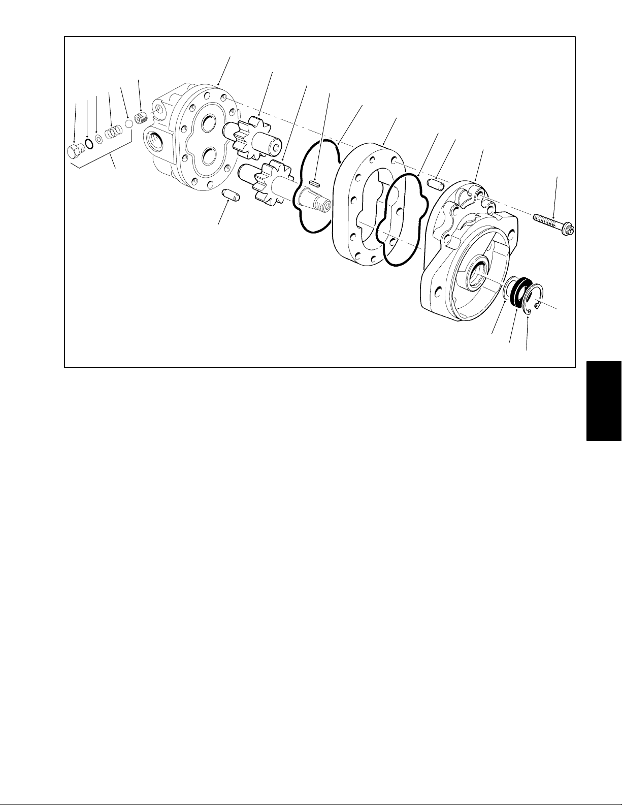
7
6
5
4
3
2
1
8
9
10
11
12
11
13
14
19
1. Plug
2. O–ring
3. Shim
4. Spring
5. Ball
6. Relief valve seal
7. Backplate
13
Figure 56
8. Idler gear assembly
9. Drive gear assembly
10. Key
11. O–ring
12. Body
13. Alignment pin
15
18
17
16
14. Frontplate
15. Screw
16. Retaining ring
17. Oil seal
18. Backup washer
19. Relief valve assembly (# 1 thru 5)
System
Hydraulic
Disassembly (Fig. 56)
7. Remove body (12) from the backplate (7). Remove
O–rings (11) from the body (12) and backplate (7).
1. Make sure key (10) is removed from the drive gear
(9) shaft.
2. Matchmark frontplate (14), body (12), and backplate (7) to assure proper reassembly.
3. Secure the motor in a vise with the drive shaft up.
8. Remove Alignment pin (13) from the backplate (7).
9. Remove retaining ring (16), oil seal (17), and back-
up washer (18) from the frontplate (14).
IMPORT ANT : Do not remove the relief valve assembly (19) unless testing shows it to be faulty . The re-
4. Remove all eight screws (15).
lief valve assembly must be replaced as a complete
unit. Both relief valve seals (6) are sealed in place
5. Remove the motor from the vise. Remove the front-
with loctite; do not remove them.
plate (14) from the body (12). A wooden block or soft
face hammer might be used the gently tap the motor
when freeing the frontplate (14).
10. Remove plug (1), O–ring (2), shim (3), spring (4),
and ball (5 ) from the backplate (7).
6. Remove alignment pin (13) from the body (12). Remove drive gear (9) and idler gear (8) from the body (12).
Reelmaster 2300–D/2600–D Hydraulic SystemPage 4 – 61
Page 100

Inspection (Fig. 56)
1. Remove all nicks and burrs from all parts with an
emery cloth
CAUTION
Use eye protection such as goggles when
using compressed air
13. Make sure both plugs (1) are secure if they or the
backplate is not being replaced.
Reassembly (Fig. 56)
1. If replacing the relief valve assembly (19), install ball
(5), spring (4), shim (3), O–ring (2), and plug (1) into the
backplate (7). Hand tighten plug (1) and then torque
from 10 to 12 ft–lb (1.38 to 1.66 kg–m).
2. Coat O–ring (11) lightly with petroleum jelly and
install in groove on the front plate (14).
2. Clean all parts with solvent. Dry all parts with compressed air.
3. Inspect drive gear (9) shaft for a broken or chipped
keyway .
4. Inspect drive gear (9) and idler gear (8) shafts at the
bushing points and seal area for rough surfaces and excessive wear.
5. Replace drive gear (9) or idler gear (8) if the shaft in
the bushing area diameter measures less than 0.748 in.
(19.0 mm). A single gear may be replaced separately.
6. The drive gear (9) and idler gear (8) face should be
free of excessive scoring and wear.
7. Replace drive gear (9) or idler gear (8) if gear width
is less than 1.140 in. (29.96 mm).
8. Make sure that retaining rings are in the grooves on
both sides of the gear for both the drive gear (9) and idler
gear (8).
9. Break sharp edges of gear teeth with emery cloth.
10. Replace backplate (7) and frontplate (14) if bushing
inside diameters exceed 0.755 in. (19.2 mm). The bushings are not available as replacement items.
11. The face of the backplate (7) and frontplate (14)
should be free of excessive scoring. Replace if scoring
a depth of 0.0015 in. (0.038 mm).
3. Apply a thin coat of petroleum jelly to both gear
pockets of the body (12). Install alignment pin (13) into
body (12).
4. Align matchmarks and slip body (12) onto front plate
(14) until alignment pin (13) is engaged.
5. Dip idler gear (8) and drive gear (9) into clean hydraulic oil and slip into front plate (14) bushings.
6. Coat O–ring (11) lightly with petroleum jelly and
install in groove on the back plate (7).
7. Install alignment pin (13) into back plate (7).
8. Align matchmarks and slip back plate (7) over gear
shafts onto body (12) until alignment pin (13) is engaged.
9. Hand tighten cap screws (15) and torque in a crisscross pattern from 25 to 28 ft–lb (3.46 to 3.87 kg–m).
10. Place washer (18) over the drive shaft into the front
plate (14) housing. Apply a liberal coat of hydraulic oil to
the oil seal (17). Install oil seal (17) over the drive shaft
being careful not tho cut the rubber seal lips.
11. Place 1–1/16 inch O.D. sleeve over the drive shaft
and press in the oil seal (17) until the retaining ring
groove appears.
12. Press retaining ring (16) into the housing using the
sleeve until it seats in the groove.
12. Replace body (12) if the inside diameter of the gear
pockets exceeds 1.713 in. (43.5 mm).
Reelmaster 2300–D/2600–DHydraulic System Page 4 – 62
 Loading...