

Page 1

Installation
LooseParts
FormNo.3386-813RevA
RearSteeringIndicatorKit
RT600TractionUnit
ModelNo.25520
ModelNo.25520E
InstallationInstructions
WARNING
CALIFORNIA
Proposition65Warning
ThisproductcontainsachemicalorchemicalsknowntotheStateofCaliforniato
causecancer,birthdefects,orreproductiveharm.
Usethechartbelowtoverifythatallpartshavebeenshipped.
ProcedureDescription
1
2
3
4
5
6
Nopartsrequired
Rear-steeringindicatordecal(125-6697)
Steeringwarningdecal(125-8471)
Nopartsrequired
Position-indicatorcable1
Locknut(M10)
Balljoint1
Plate1
Flangenut(3/8inch)
Clamp(3/8x3/8inch)
Hex-headscrew(3/8x1inch)
Nopartsrequired
Locknut(M10)
Position-indicatorpointer1
Qty.
Use
–
1
1
–
1
1
1
1
–
2
Preparethemachine.
Applythedecalstothesteering-indicator
plate.
Removetherightfenderfromthe
machine.
Installtheposition-indicatorcable.
Installtherightfenderontothemachine.
Installtheposition-indicatorpointer.
©2014—TheToro®Company
8111LyndaleAvenueSouth
Bloomington,MN55420
Registeratwww.T oro.com.
OriginalInstructions(EN)
PrintedintheUSA
AllRightsReserved
*3386-813*A
Page 2
1
2
PreparingtheMachine
NoPartsRequired
Procedure
1.Movethemachinetoalevelsurface.
2.Settheparkingbrakeandlowertheattachmentsto
theground
3.Shutoffthemachineandremovethekey.
4.Useajackwithacapacityof2,494kg(5,500lb)toraise
themachineattherearaxle.
WARNING
Raisingtheunitrelyingsolelyonmechanical
orhydraulicjackscouldbedangerous.The
mechanicalorhydraulicjacksmaynotbe
enoughsupportormaymalfunctionallowing
theunittofall,whichcouldcauseinjuryor
death.
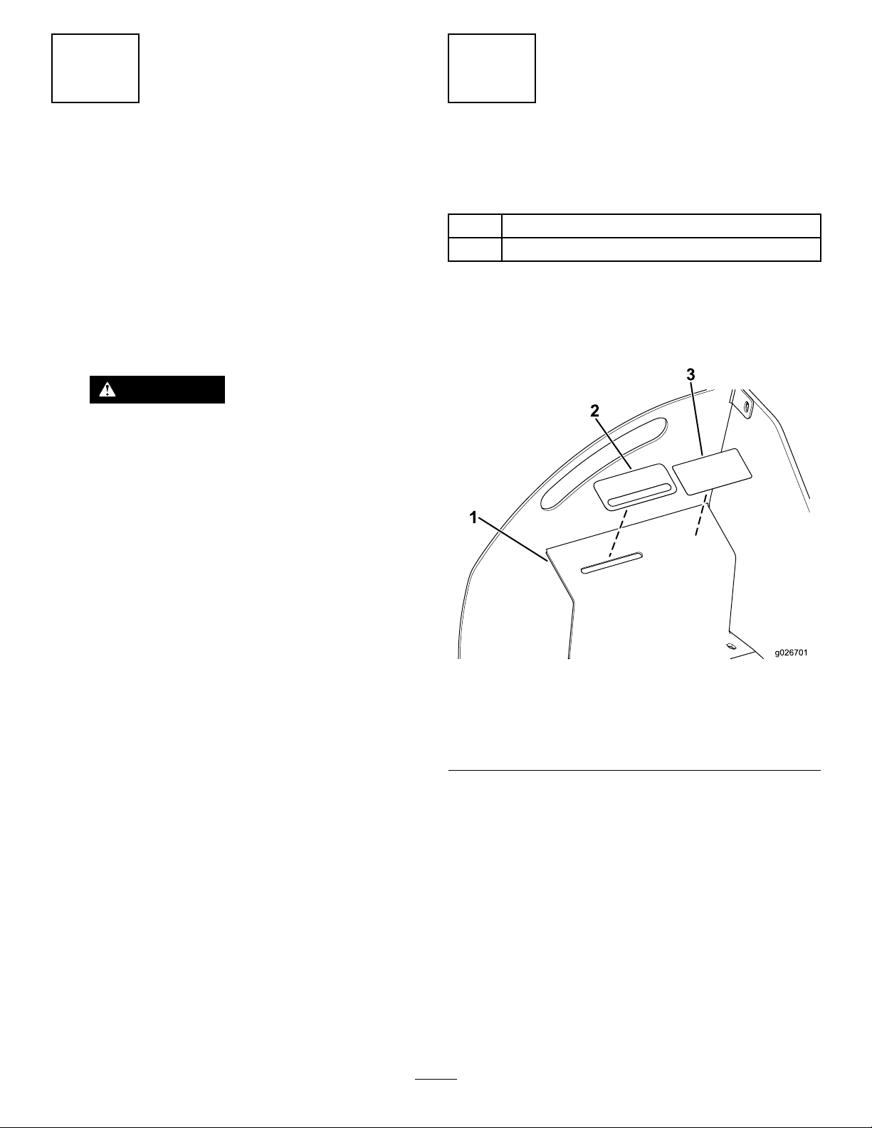
ApplyingtheDecalstothe Steering-indicatorPlate
Partsneededforthisprocedure:
1
Rear-steeringindicatordecal(125-6697)
1
Steeringwarningdecal(125-8471)
Procedure
Applythedecalstothesteering-indicatorplateasshownin
Figure1.
Donotrelysolelyonmechanicalorhydraulic
jacksforsupport.
Useadequatejackstandsorequivalent
support.
5.Usejackstandswithacapacityof2,494kg(5,500lb)
tosupportthebackofthemachine.
6.Removetheright,rearwheel.
Figure1
1.Steering-indicatorplate3.Steeringwarningdecal
(125-8471)
2.Rear-steeringindicator
decal(125-6697)
2
Page 3
3
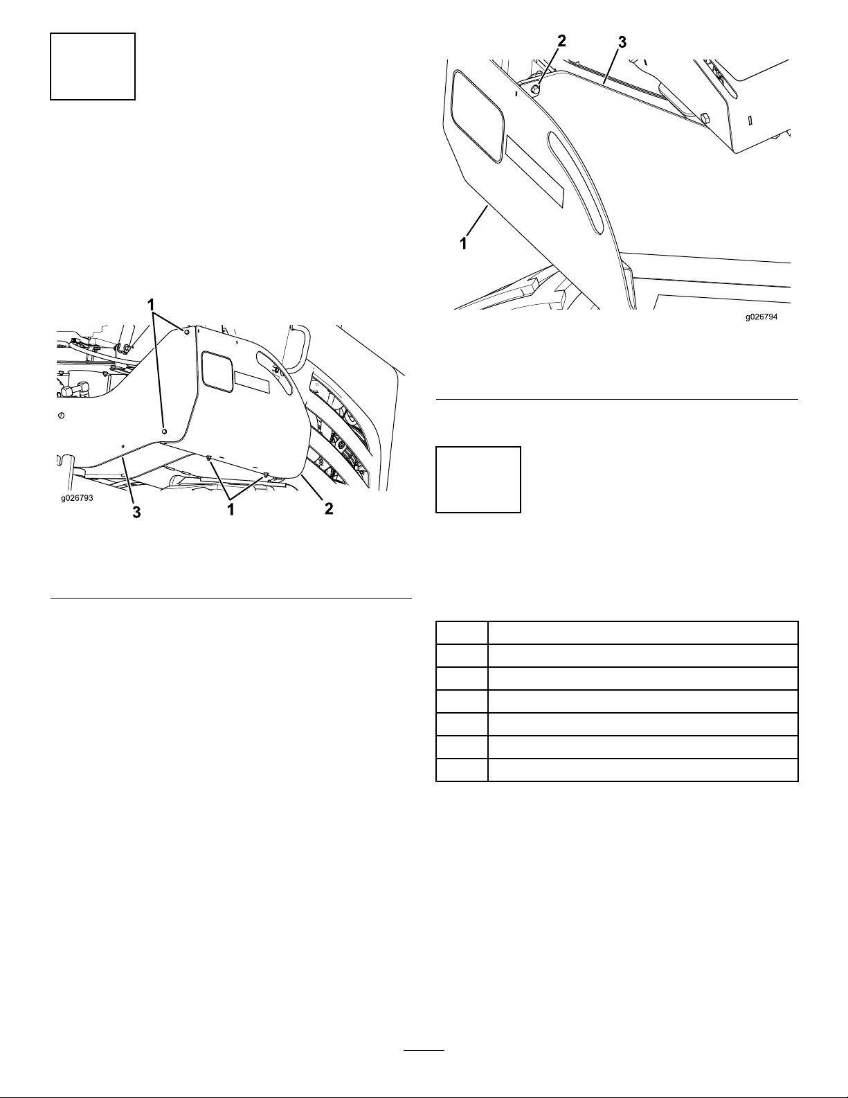
RemovingtheRightFender fromtheMachine
NoPartsRequired
Procedure
1.Removethe2boltsandlocknutsfromthesideofthe
backROPSplate(Figure2).
Figure3
1.Rightfender3.FrontROPSplate
2.Boltandlocknut
4.Removetherightfenderfromthemachine(Figure3).
Figure2
1.Boltsandlocknuts
2.Rightfender
2.Removethe2boltsandlocknutsfromthebottomof
therightfender(Figure2).
3.RemovetheboltandlocknutfromthefrontROPS
plate(Figure3).
3.BackROPSplate
4
Installingthe Position-indicatorCable
Partsneededforthisprocedure:
1Position-indicatorcable
1
Locknut(M10)
1Balljoint
1Plate
1
Flangenut(3/8inch)
1
Clamp(3/8x3/8inch)
1
Hex-headscrew(3/8x1inch)
Procedure
1.Insertoneendoftheposition-indicatorcablethrough
theopeninginthefrontROPSplateintotheopening
inthesteering-indicatorplate(Figure4).
3
Page 4

Figure4
1.Steering-indicatorplate
2.FrontROPSplate
3.Position-indicatorcable
2.Securetheposition-indicatorcabletothebackROPS
platewiththeangenut(3/8inch),clamp(3/8x3/8
inch),andthehex-headscrew(3/8x1inch)asshown
inFigure5.
Figure6
1.Position-indicatorcable2.Rear-steeringmount
4.Securetheposition-indicatorcabletotherearaxlewith
theplate,locknut(M10),andtheballjoint(Figure7).
Figure7
1.Position-indicatorcable3.Plate
2.Balljoint
4.Locknut(M10)
Figure5
1.Position-indicatorcable
2.Flangenut(3/8inch)5.BackROPSplate
3.Clamp(3/8x3/8inch)
4.Hex-headscrew(3/8x1
inch)
3.Routetheotherendoftheposition-indicatorcable
throughtheopeningintherear-steeringmountonthe
rearaxle(Figure6).
4
Page 5

5
6
InstallingtheRightFender ontotheMachine
NoPartsRequired
Procedure
1.Aligntherightfenderwiththeholeswherethe5bolts
andthe5locknutswereremovedin3Removingthe
RightFenderfromtheMachine(page3).
2.Installthe5boltsandthe5locknutsintotheback
ROPSplate,frontROPSplate,andtherightfender
(Figure2andFigure3).
Installingthe Position-indicatorPointer
Partsneededforthisprocedure:
2
Locknut(M10)
1Position-indicatorpointer
Procedure
1.Inserttheposition-indicatorcablethroughthesideof
thesteering-indicatorplate(Figure8).
Figure8
1.Position-indicatorpointer3.Position-indicatorcable
2.Steering-indicatorplate4.Locknuts(M10)
2.Install2locknuts(M10)andtheposition-indicator
pointerontotheposition-indicatorcable(Figure8).
3.Positiontheposition-indicatorpointertothemiddleof
theopeninginthesteering-indicatorplate(Figure9).
Figure9
1.Steering-indicatorplate
2.Openingforthe
position-indicatorpointer
3.Position-indicatorpointer
5
Page 6

Operation
CenteringtheRearWheels
Centertherearwheelsfromlefttorightbyadjustingtheball
jointandthelocknutattheendoftheposition-indicatorcable
untiltheindicatorattheoperator’spositionshowsthatthe
wheelsarestraight(Figure10).
Figure10
1.Position-indicatorcable
2.Balljoint
3.Locknut(M10)
6
Page 7

Notes:
7
Page 8

 Loading...