

Page 1
FormNo.3405-597RevA
TrencherSlidingOffsetMountKit
RT1200TractionUnit
ModelNo.25514
ModelNo.25514E
InstallationInstructions
Safety
WARNING
CALIFORNIA
Proposition65Warning
ThisproductcontainsachemicalorchemicalsknowntotheStateofCaliforniato
causecancer,birthdefects,orreproductiveharm.
SafetyandInstructionalDecals
Safetydecalsandinstructionsareeasilyvisibletotheoperatorandarelocatednearanyareaofpotential
danger.Replaceanydecalthatisdamagedorlost.
125-6107
1.Crushinghazardofhandandfoot—keephandsandfeet
away.
©2016—TheT oro®Company
8111LyndaleAvenueSouth
Bloomington,MN55420
Registeratwww.T oro.com.
125-6690
1.Wholebodycrushinghazard—keepawayfromthemachine
wheninoperation.
OriginalInstructions(EN)
PrintedintheUSA
AllRightsReserved
*3405-597*A
Page 2
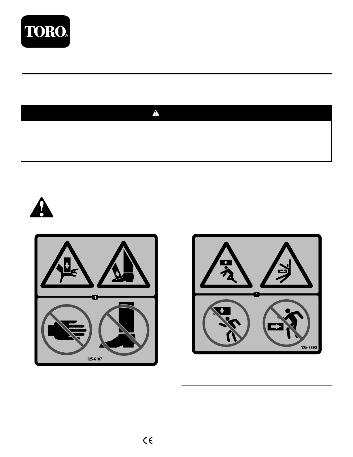
1.Tie-downpoint
1.Liftpointandtie-downpoint
125-6694
125-6139
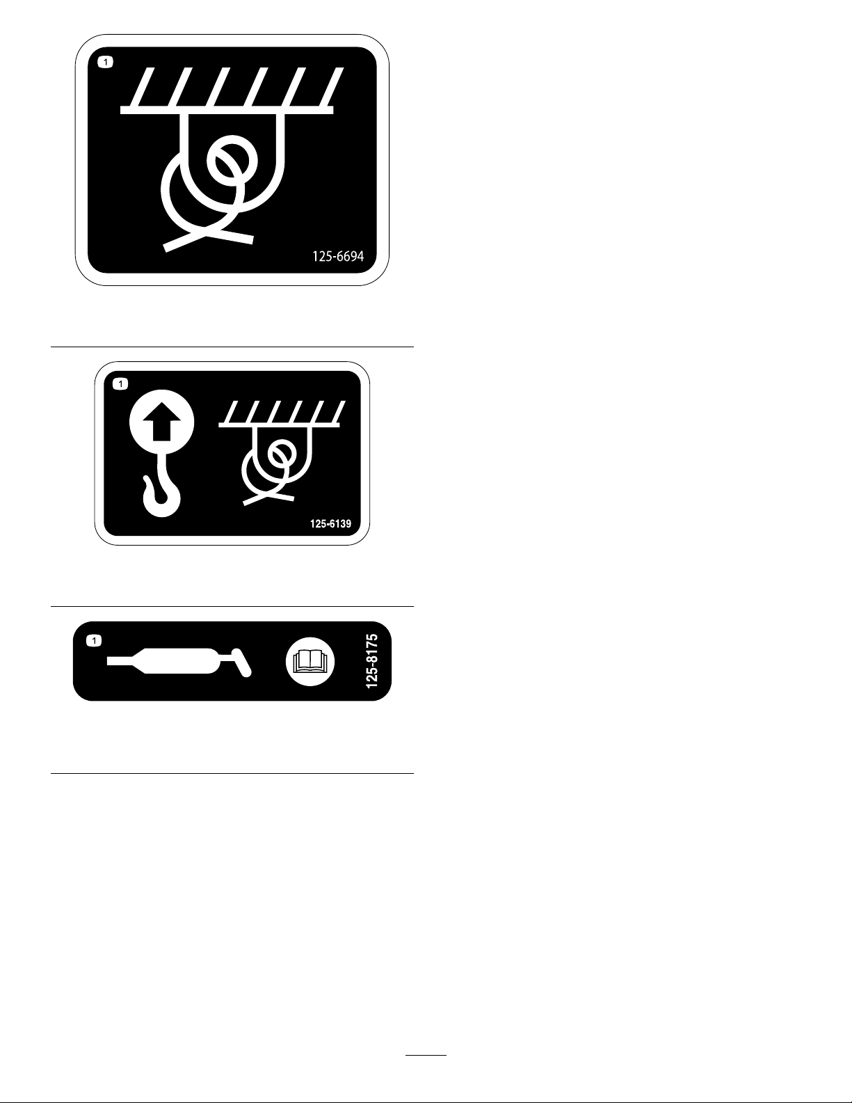
125-8175
1.ReadtheOperator’sManualforinformationongreasing
themachine.
2
Page 3

Installation
LooseParts
Usethechartbelowtoverifythatallpartshavebeenshipped.
ProcedureDescription
1
2
3
4
5
6
Nopartsrequired
Switch
Bolt(1x4inch)
Bolt(1x41/2inch)
Washer21
Nut11
Retainingring2
Clevispin
Upperspacerplate1
Uppermiddlespacerplate(withgrease
ttings)
Retainerplate2
Lowermiddlespacerplate(withgrease
ttings)
Lowerspacerplate1
Adaptertting
1481/2cm(581/2-inch)hose
160cm(63-inch)hose
170cm(67inch)hose
170cm(67inch)hose
165cm(65inch)hose
Qty.
–
1Instaltheswitch.
9
2
1
1
1
2Installthehydrauliccylinderhoses.
1
1
1
1
1
Preparethemachine.
Installtheslidingoffsetattachment.
Installthetrenchercylinderhoses.
Installthetrenchermotorhydraulic
hoses.
Use
7
8
65cm(251/2inch)Hose
Nopartsrequired
2Installthehydrauliccrumberhoses.
–
Testtheswitch.
3
Page 4
1
PreparingtheMachine
NoPartsRequired
Procedure
1.Movethemachinetoalevelsurface.
Note:Ensurethatthefrontwheelsofthemachine
arestraight.
2.Loweranyattachments.
3.Settheparkingbrake,shutofftheengine,andremove
thekeyfromthekeyswitch.
4.Rotatethebattery-disconnectswitchtotheOFF
position;refertotheOperator’ sManual.
Important:Ensurethattheliftingequipmenthasa
liftingcapacityofatleast405kg(893lb).
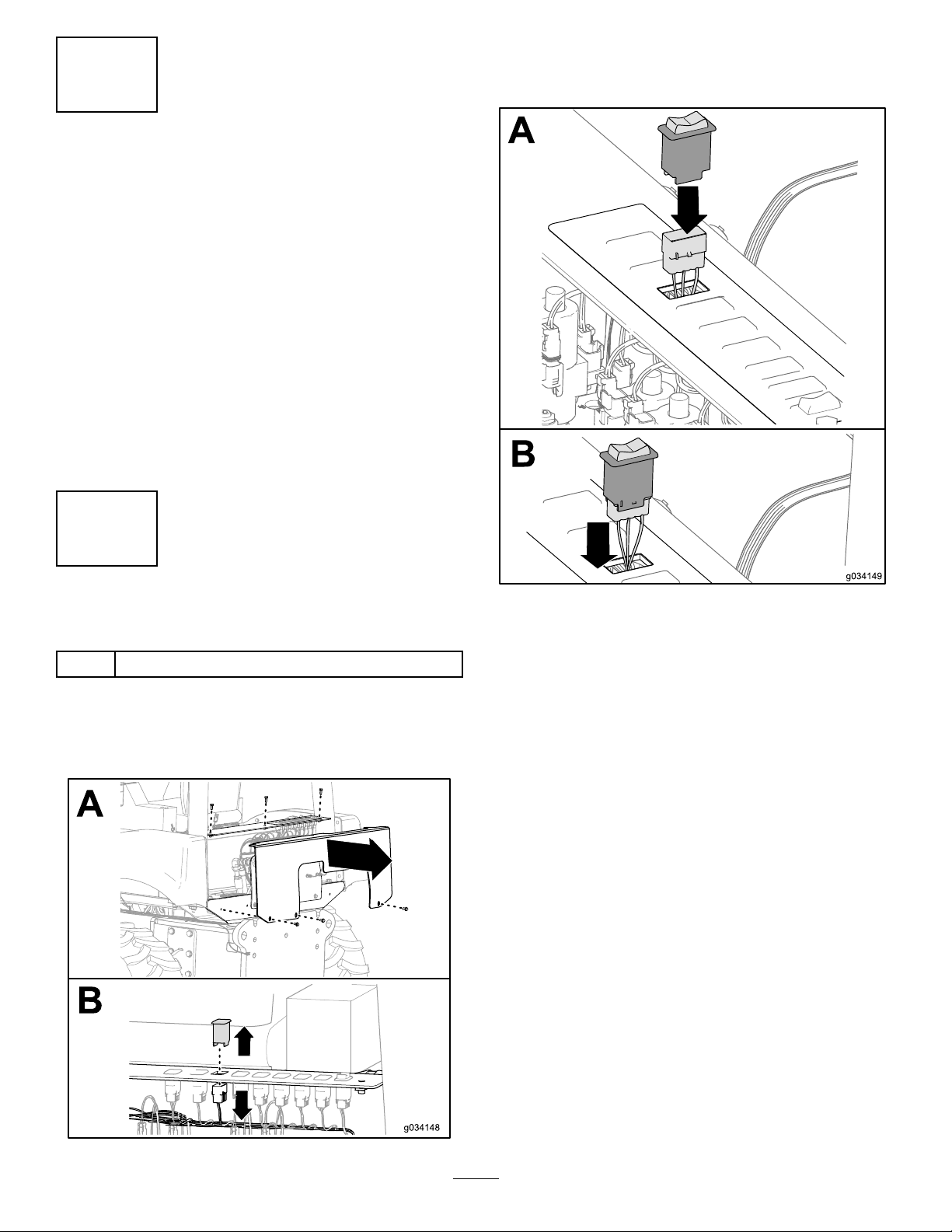
2.Removetheblankingplatefromtheauxiliary-control
panelandpulltheconnectorofthewiringharnessof
themachinethroughtheswitchopening.
2
InstallingtheSwitch
Partsneededforthisprocedure:
1
Switch
Procedure
1.Removetherear-coverplatetotherearbulkheadof
themachine.
3.Connecttheconnectorofthewiringharnesstothe
switchandsnaptheswitchintotheauxiliary-control
panel.
4
Page 5

3
InstallingtheSlidingOffset
Attachment
Partsneededforthisprocedure:
9
Bolt(1x4inch)
2
Bolt(1x41/2inch)
21Washer
11Nut
2Retainingring
1
Clevispin
1Upperspacerplate
1
Uppermiddlespacerplate(withgreasettings)
2Retainerplate
1
Lowermiddlespacerplate(withgreasettings)
1Lowerspacerplate
6.Securetheslidemountplatetothecylinderusingthe
clevispinand2retainingrings.
InstallingtheAttachmentontoa
WheeledMachine
1.Removethetrencherattachmentfromthemachine.
2.Raisetheslidingoffsetattachmentofftheoorusing
liftingequipment.
3.Securetheslidingoffsetframeontothemachineusing
6bolt(1x4),12washers,and6nuts.
4.Torquetheboltsto686to882N∙m(506to651ft-lb).
5.Spreadsomegreaseontherightsideoftheattachment
frame.
7.Placetheupperandlowerspacerplatesontheslide
mountplateholdingtheminplacewiththe2bolts(3/4
x4inch)and2washers.
5
Page 6

8.Raisethetrencherattachmentofftheoorusinglifting
equipment.
InstallingtheAttachmentontoa
TrackedMachine
1.Removetheattachmentfromthespacer.
Note:Donotdiscardthehardware.
Note:Keepthespacerinstalledonthemachine.
Important:Ensurethattheliftingequipmenthas
aliftingcapacityofatleast405kg(893lb).
9.Locatethe2rowsofholesinthemountingplatethat
youwillusetosecuretheattachmenttothesliding
offsetattachment.
10.Lowerthetrencherattachmentuntilitisalignedwith
theslidemountassembly .
11.Securethetrenchertotheoffsetattachmentusing3
bolts(1x4inch),6washers,and3nuts.
12.Torquetheboltsto686to882N∙m(506to651ft-lb).
13.Insert2bolts(1x41/2inch)and2washersthrough
theinnermostholesontheslidemountassembly.
2.Raisetheslidingoffsetattachmentofftheoorusing
liftingequipment.
3.Installthe2longboltspreviouslyremovedintheoffset
attachment.
14.Securethetopboltwithanut.
15.Securethebottomboltwithawasherandanut.
16.Torquetheboltsto686to882N∙m(506to651ft-lb).
6
Page 7

4.Securethe2longboltswith2nuts;torquetheboltsto
686to882N∙m(506to651ft-lb).
5.Install2nutsontotheboltsalreadyinstalledonthe
spacer;torquetheboltsto686to882N∙m(506to651
ft-lb).
6.Insert1bolt(1x4inch)and1washerthroughthe
offsetattachmentthroughtheholeontheunderside
ofthespacer.
7.Securetheboltwith1washerand1nut;torquethe
boltsto686to882N∙m(506to651ft-lb).
8.Securethetoppartoftheoffsettothespacerusing2
bolts,4washers,and2nuts;torquetheboltsto686to
882N∙m(506to651ft-lb).
9.Installthetrencherattachmentontotheoffsetslider;
refertosteps8tostep16in(page).
7
Page 8

InstallingtheHosesontotheLarge
Manifold
4
InstallingtheHydraulic CylinderHoses
Partsneededforthisprocedure:
2
Adaptertting
InstallingtheHosesontotheSmall
Manifold
1.Installtheadapterttingsontotheports.
1.Installtheadapterttingsontotheports.
2.Installthehosethatiscomingfromtherodendof
thehydrauliccylindertotheadapterinstalledonthe
topport.
3.Torquethettingsto48to58N∙m(35to43ft-lb).
4.Installthehosethatiscomingfromthebaseendof
thehydrauliccylindertotheadapterinstalledonthe
bottomport.
5.Torquethettingsto48to58N∙m(35to43ft-lb).
2.Installthehosethatiscomingfromtherodendof
thehydrauliccylindertotheadapterinstalledonthe
leftport.
3.Torquethettingsto48to58N∙m(35to43ft-lb).
4.Installthehosethatiscomingfromthebaseendof
thehydrauliccylindertotheadapterinstalledonthe
rightport.
5.Torquethettingsto48to58N∙m(35to43ft-lb).
8
Page 9

5
InstallingtheTrencher CylinderHoses
Partsneededforthisprocedure:
1
1481/2cm(581/2-inch)hose
1
160cm(63-inch)hose
Procedure
Figure13
1.Hydraulicpressure4.Raisetheattachment.
2.Lowertheattachment.5.Hydraulicreturn
3.Casedrain
1.Installthe1481/2cm(581/2inch)hosefromthe
attachmentraiseport(Figure13)tothelowerporton
thetrencherhydrauliccylinder(Figure14).
Figure14
2.Torquethettingsto31to39N∙m(23to29ft-lb).
3.Installthe160cm(63inch)hosefromtheattachment
lowerport(Figure13)totheupperportonthetrencher
hydrauliccylinder(Figure14).
4.Torquethettingsto20to28N∙m(15to21ft-lb).
9
Page 10

6
InstallingtheTrencherMotor HydraulicHoses
Partsneededforthisprocedure:
1
170cm(67inch)hose
1
170cm(67inch)hose
1
165cm(65inch)hose
5.Installthe170cm(67inch)hosefromthehydraulic
returnport(Figure13)totheupperportonthe
trenchermotorasshowninFigure17.
Procedure
1.Installthe170cm(67inch)hosefromthehydraulic
pressureport(Figure13)tothelowerportonthe
trenchermotorasshowninFigure15.
Figure15
2.Torquethettingsto207to230N∙m(153to187ft-lb).
3.Installthe165cm(65inch)hosefromthecasedrain
port(Figure13)totheportonthetrenchermotoras
showninFigure16.
Figure17
6.Torquethettingsto207to230N∙m(153to187ft-lb).
Figure16
4.Torquethettingsto93to115N∙m(69to85ft-lb).
10
Page 11

7
InstallingtheHydraulic CrumberHoses
Partsneededforthisprocedure:
2
65cm(251/2inch)Hose
Procedure
Removethettingsfromthe2crumberhoses.
Connectthe2hoses(25-1/2inch)tothemachine.
Connectthehosestothecrumberhoses.
11
Page 12

8
TestingtheSwitch
NoPartsRequired
Procedure
Presstheswitchtoposition5ofFigure21.Thetrencherdriveshouldshifttothecenterofthemachine.
Presstheswitchtoposition6ofFigure21.Thetrencherdriveshouldshifttotherightsideofthemachine.
Figure21
Operation
UsingtheSlidingOffsetKit
Refertotheauxiliary-controlpaneldecalonyourmachine
(Figure21).
Maintenance
GreasingtheSliderFrame
ServiceInterval:Every50hours
GreaseType:Lithium-basedgrease.
Lowertheattachmenttothegroundtoensurethatthegrease
owsintothettingsproperly.
Cleanthegreasettingswitharag.
Connectthegreaseguntothegreasettingsfortheupper
andlowerpivots;apply2or3pumpsofgreasetoeachtting
(Figure22).
Figure22
12
 Loading...