

Page 1

FormNo.3394-809RevB
12inBoomExtension
RT1200Trencher
ModelNo.25513
ModelNo.25513E
InstallationInstructions
WARNING
CALIFORNIA
Proposition65Warning
ThisproductcontainsachemicalorchemicalsknowntotheStateofCaliforniato
causecancer,birthdefects,orreproductiveharm.
WARNING
Whentheengineisoff,attachmentsintheraisedpositioncangraduallylower.Someonebelowthe
attachmentmaybepinnedorinjuredbytheattachmentasitlowers.
Alwayslowertheattachmenteachtimeyoushutoffthetractionunit.
Installation
1
PreparingtoInstalltheBoom
Extension
NoPartsRequired
PreparingtheMachine
1.Movethemachinetoalevelsurfacethatisbelowthe
liftingequipment.
2.Lowerallattachments.
3.Ensurethatthetiltfeatureofthemachineisleveland
thetilt-lockoutpinissecuretothechassis-lockout
bracket;refertotheOperator’sManualforthemachine.
PreparingaNewCenterTrencher
Note:Refertothefollowingsetupproceduresinthecenter
trencherOperator’ sManualfortheRT1200tractionunit.
1.PreparingtoInstalltheTrencher
2.InstallingtheSpeed-ShiftSwitch
3.InstallingtheTrencherAttachment
4.PreparingtheHydraulicMotor
5.ConnectingtheLiftCylinderHoses
6.InstallingtheHydraulicHoses
7.ConnectingtheWiringHarnesstotheHydraulicMotor
8.PurgingAirfromtheHydraulicMotorandLift
9.InstallingtheSprocket
10.InstallingtheAuger
Cylinder
4.Shutoffthemachine,settheparkingbrake,and
removethekeyfromthekeyswitch.
©2015—TheT oro®Company
8111LyndaleAvenueSouth
Bloomington,MN55420
Registeratwww.T oro.com.
OriginalInstructions(EN)
PrintedintheUSA
AllRightsReserved
*3394-809*B
Page 2
2
3
RemovingtheDiggingChain
NoPartsRequired
Procedure
Machineswithaninstalledtrencher
Restraintbarweightfora
122cm(48inch)rockboom
Restraintbarweightfora
152cm(60inch)rockboom
Crumberweightfora122
cm(48inch)rockboom
Crumberweightfora152
cm(60inch)rockboom
1.Useliftingequipmentasneededtosupporttherestraint
barorcrumber.
2.Removethe4bolts(5/8x11inch)and4locknuts
(5/8inch)thatsecuretherestraintbarorcrumber,and
removethebar(Figure1).
11kg(24lb)
14kg(30lb)
60kg(125lb)
68kg(151lb)
RemovingtheBoom
NoPartsRequired
Procedure
Machineswithaninstalledtrencher
122cm(48inch)rockboom
weight
152cm(60inch)rockboom
weight
1.Starttheengineofthemachine;refertothetraction
unitOperator’sManual.
2.Usetheattachment-elevationswitchtomovethe
boom-mountttingofthetrenchertothehorizontal
position.
3.Attachtheliftingequipmenttotherockboom,and
supporttheboom(Figure2).
Important:Ensurethattheliftingequipmenthas
aliftcapacityofatleast293kg(645lb)forthe122
cm(48inch)rockboomor320kg(705lb)fora152
cm(60inch)rockboom.
212kg(466lb)
239kg(526lb)
Figure1
1.Locknut(5/8inch)
2.Bolt(5/8x1 1inch)4.Restraintbar(shown)
3.Removethediggingchain;refertotheRemovingthe
DiggingChainprocedureintheMaintenancesection
ofthecentertrencherOperator’sManualfortheRT1200
tractionunit.
3.Bar-mountingplates
Figure2
4.Removethe2hex-headbolts(3/4x2-1/2inch),2
washers,and2serrated-angenutsattheverticalholes
inthemountingplateandtheboom-mounttting
(Figure3).
2
Page 3

Figure3
1.Locknut(3/4inch)6.Washer(1inch)
2.Serrated-angenut(3/4
inch)
3.Hex-headbolts(3/4x
2-1/2inch)
4.Washer(3/4inch)9.Hex-headbolts(1x2-1/2
5.Flangelocknut(1inch)
7.Boom-mounttting
(trencher)
8.Mountingplate(rock
boom)
inch)
5.Removethe2hex-headbolts(3/4x2-1/2inch),2
washers,and2locknutsatthehorizontalholesinthe
mountingplateandtheboom-mounttting(Figure3).
6.Removethe2horizontalbolts(1x2-1/2inch),
4washers(1inch),and2locknuts(1inch)atthe
horizontalholesinthemountingplateandthe
boom-mounttting(Figure3).
4
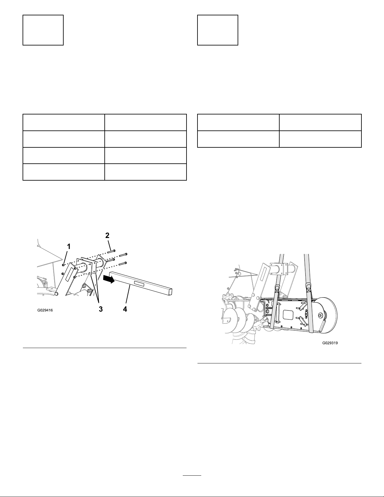
AssemblingtheBoom
ExtensiontotheRockBoom
Partsneededforthisprocedure:
1Boomextension
2
Bolt(1x2-1/2inch)
2
Washer(1inch)
2
Locknut(1inch)
4
Bolt(3/4x2-1/2inch)
4
Washer(3/4inch)
4
Locknut(3/4inch)
Procedure
Boom-extensionweight:81kg(179lb)
Note:Usethebolts,washers,andnutsfromthe
boom-extensionkittoassembletheboomextensiontothe
rockboom.
1.Aligntheholesintheboomextensionwiththeholes
intherockboomasshowninFigure4.
Note:Retaintheboltswashersandnutsforinstalling
theassembledrockboomandextension.
7.Movetheboomawayfromthetrenchertoprovide
clearanceforattachingtheboomextensiontothe
boom.
Figure4
1.Washer(3/4inch)—12
inchboomextensionkit
2.Bolt(3/4x2-1/2inch)—12
inchboomextensionkit
3.Locknut(3/4inch)—12
inchboomextensionkit
4.Mountingplate(boom
extension)
5.Boom-mounttting
(trencher)
2.Applythread-lockingcompoundtothethreadsofthe
4bolts(1x2-1/2inch)and2bolts(1x2-1/2inch).
3.Assemblethe2bolts(3/4x2-1/2inch),2washers
(3/4inch),and2locknuts(3/4inch)atthevertical
holesinthemountingplatefortheboomextension
andthemountingplatefortherockboom(Figure4).
4.Assemblethe2bolts(3/4x2-1/2inch),2washers
(3/4inch),and2locknuts(3/4inch)atthehorizontal
3
Page 4
holesinthemountingplatefortheboomextension
andthemountingplatefortherockboom(Figure4).
5.Assemblethe2bolts(1x2-1/2inch),4washers(1
inch),and2locknuts(1inch)atthehorizontalholesin
themountingplatefortheboomextensionandthe
mountingplatefortherockboom(Figure4).
6.Tightentheboltsandlocknutsbyhand.
5
InstallingtheBoomExtension
andRockBoom
NoPartsRequired
Procedure
122cm(48inch)Rockboom
weightwithextension:
152cm(60inch)Rockboom
weightwithextension:
Note:Ifyouareinstallingacentertrencheralongwiththe
12-inchboomextension,usethebolts,washers,andnuts
fromthecenter-trencherkittoassemblethe12-inchboom
extensionandrockboomtothetrencher;refertotheoperator’s
manuallforthecentertrencher.Ifyouremovedtherock
boomfromanexistingtrencherinstallation,usethehardware
youremovedin3RemovingtheBoom(page2)toinstallthe
12-inchboomextensionandrockboom.
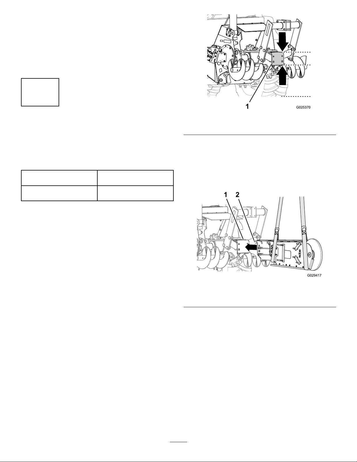
1.Starttheengineofthemachine;refertothetraction
unitOperator’sManual.
2.Ensurethattheboommountttingforthetrencheris
inthehorizontalposition(Figure5).
Note:Ifneeded,usetheattachment-elevationswitch
tomovethemounttting.
293kg(645lb)
320kg(705lb)
Figure5
1.Boom-mountingttingonthetrencher
3.Ensurethattheextensionandrockboomarelevel
(Figure6).
Important:Ensurethattheliftingequipmenthas
aliftcapacityofatleast293kg(645lb)forthe122
cm(48inch)rockboomor320kg(705lb)fora152
cm(60inch)rockboom.
Figure6
1.Boom-mountttingonthe
trencher
4.Positiontheboomextensionandrockboomsothat
themountingplateoftheextensionisushwiththe
boom-mountttingonthetrencher,andtheholesin
theplatearealignedwiththeholesinthetting(Figure
6).
2.Mountingplateonthe
boom
5.Applymedium-gradethread-lockingcompoundtothe
4hex-headbolts(3/4x2-1/2inch).
Note:Formachineswithanexistingtrencherinstalled,
refertosteps4and5of3RemovingtheBoom(page
2).
6.Install2hex-headbolts(3/4x2-1/2inch),washers,
andnutsintotheverticalholesinthemountingplate
andtheboom-mounttting(Figure7).
4
Page 5
1.Hex-headbolts(3/4x
2-1/2inch)—optional
centertrencherkit
2.Washer(3/4
inch)—optionalcenter
trencherkit
3.Serrated-angenut(3/4
inch)—optionalcenter
trencherkit
Figure7
4.Locknut(3/4
inch)—optionalcenter
trencherkit
5.Boom-mounttting
(trencher)
6.Mountingplate(boom
extension)
6
AligningtheBoom
Partsneededforthisprocedure:
3
Shim(centertrencherkit)
3
Shim(12inchboomextensionkit)
AligningtheBoomattheBoom-Mount
FittingandBoomExtension
Installerprovidedtool:straightedge—152cm(60inch)for
the48-inchrockboomandextension;274cm(108inch)for
the60-inchrockboomandextension.
1.Alignastraightedgeagainstthedrivesprocketforthe
diggingchainandacrosstheendroller(Figure8).
7.Install2hex-headbolts(3/4x2-1/2inch),washers,
andnutsintothehorizontalholesinthemounting
plateandtheboom-mounttting(Figure7).
Note:Ensurethatthemountingplateontheboom
extensionisushwiththeboom-mountttingonthe
trencher.
8.Torquetheboltsandnutsthatsecurethe
extension-mountingplatetotheboom-mounttting
forthetrencherto203N-m(150lb-ft).
9.Torquetheboltsandnutsthatsecurethemounting
plateoftherockboomtothemountttingofthe
boomextensionto203N-m(150lb-ft).
10.Removetheliftingequipment.
Figure8
Leftoffsetshown
1.DimensionAgap
2.Endroller
3.Straightedge—152cm
(60inch)forthe48-inch
rockboomandextension;
274cm(108inch)forthe
60-inchrockboomand
extension
4.Drivesprocket(digging
chain)
2.Checkthealignmentoftheextensionandboomas
showninFigure8,andrecordyourmeasurementsin
theAlignmentWorksheetbelow:
•Left-offsetboom:Iftheboomisalignedtothe
leftofthesprocketcenterline,placeastraight
edgeacrosstherightfaceofthedrivesprocket
andmeasurethegap(dimensionA)betweenthe
5
Page 6
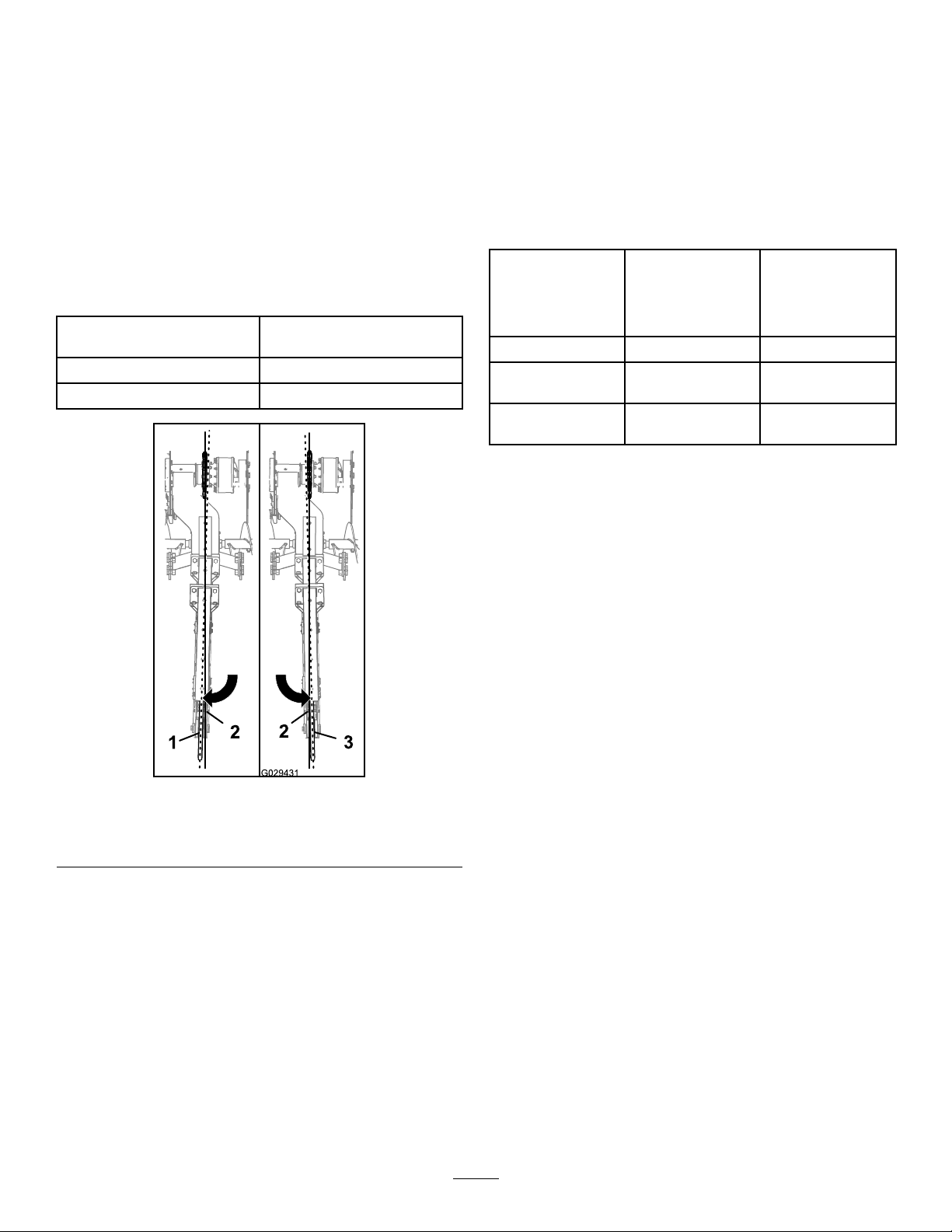
straightedgeandtheendroller(Figure8and
Figure9).
•Right-offsetboom:Iftheboomisalignedtothe
rightofthesprocketcenterline,placeastraight
edgeacrosstheleftfaceofthedrivesprocket
andmeasurethegap(dimensionA)betweenthe
straightedgeandtheendroller(Figure8and
Figure9).
•Nooffset:Theboomisaligned.
Note:IfthemeasureddimensionAgapis0to
4.8mm(0to0.1875inch),skiptostep8.
AlignmentWorksheet
YourMeasurement(leftor
rightdimensionA)
Maximum-offsetGap4.8mm(0.1875inch)
Shim-correctionDimension
completesteps5through10andperformthesteps
inAligningtheBoomattheBoomExtensionand
RockBoom(page7)
•Largerthan29.5mm(1.16inch)fora122cm(48
inch)rockboomwithboomextension.
•Largerthan30.1mm(1.39inch)fora152cm(60
inch)rockboomwithboomextension.
ShimT able—Boom-MountFittingandBoom
Extension
NumberofShims
forCorrection
1
2
3
5.Installtheliftingequipmenttotheboomandsupport
it.
122cm(48inch)
RockBoomwith
BoomExtension
Shim-correction
Dimension
9.4mm(0.37inch)9.6mm(0.44inch)
19.6mm(0.77
inch)
29.5mm(1.16
inch)
152cm(60inch)
RockBoomwith
BoomExtension
Shim-correction
Dimension
20mm(0.92inch)
30.1mm(1.39
inch)
Figure9
1.Endroller(leftoffset)3.Endroller(rightoffset)
2.Sprocketcenterline
3.Usingthealignmentworksheet,determinethe
numberofshimsthatyouneedbysubtractingthe
maximum-offsetgapof4.8mm(0.1875inch)from
yourmeasurement(dimensionA).
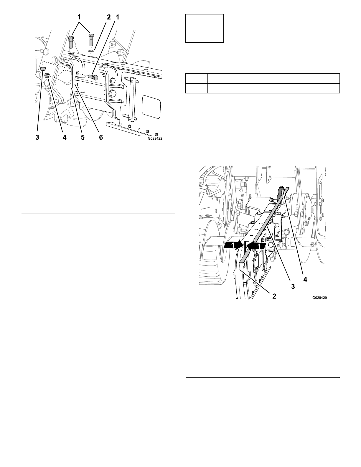
6.Attheboom-mountttingforthetrencherandthe
mountingplatefortheboomextension,loosenthe4
hex-headbolts(3/4x2-1/2inch)andnuts(Figure10).
Note:Theresultistheshim-correctiondimension.
4.Usetheshimtable(boom-mountttingandboom
extension)todeterminethenumberofshimsneeded
toaligntheboomwithinthe4.8mm(0.1875inch)
maximum-offsetgap.
Important:Iftheshim-correctiondimension
exceedsthefollowingdimensionsfortheshims
attheboom-mountttingandboomextension,
6
Page 7
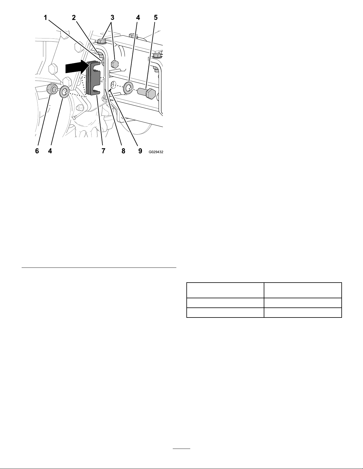
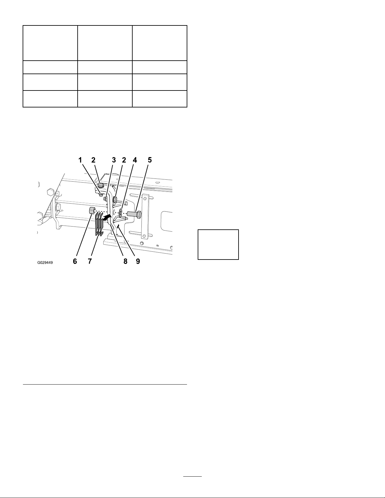
Figure10
Shiminstallationforaleft-offsetboom(boom-mounttting
andboomextension)
1.Hex-headbolts(3/4x
2-1/2inch)
2.Serrated-angenut(3/4
inch)
3.Locknut(3/4inch)8.Boom-mounttting
4.Washer(1inch)—optional
centertrencherkit
5.Hex-headbolts(1x2-1/2
inch)—optionalcenter
trencherkit
6.Flangelocknut(1
inch)—optionalcenter
trencherkit
7.Shim(s)—optionalcenter
trencherkit
(trencher)
9.Mountingplate(boom
extension)
Torquethe2bolts(1x2-1/2inch)609to641N-m
(449to473ft-lb).
11.Iftheboomisaligned,performsteps1through4in
InstallingtheBoltsfortheBoomExtensionandRock
Boom(page8).
AligningtheBoomattheBoom
ExtensionandRockBoom
1.Alignastraightedgeagainstthedrivesprocketforthe
diggingchainandacrosstheendroller;refertoFigure
8inAligningtheBoomattheBoom-MountFitting
andBoomExtension(page5).
2.Checkthealignmentoftheextensionandboom
asshowninFigure8ofAligningtheBoomatthe
Boom-MountFittingandBoomExtension(page5),
andrecordyourmeasurementsintheAlignment
Worksheetbelow:
•Left-offsetboom:Iftheboomisalignedtothe
leftofthesprocketcenterline,placeastraight
edgeacrosstherightfaceofthedrivesprocket
andmeasurethegap(dimensionA)betweenthe
straightedgeandtheendroller;refertoFigure
8andFigure9inAligningtheBoomatthe
Boom-MountFittingandBoomExtension(page
5).
•Right-offsetboom:Iftheboomisalignedtothe
rightofthesprocketcenterline,placeastraight
edgeacrosstheleftfaceofthedrivesprocketand
measurethegap(dimensionA)betweenthestraight
edgeandtheendroller;refertoFigure8and
Figure9inAligningtheBoomattheBoom-Mount
FittingandBoomExtension(page5).
7.Inserttheshimsasfollows:
•Foraleft-offsetboom,sliptheshimsbetweenthe
boom-mounttting(trencher)andthemounting
plate(boomextension)attheleftside(Figure10).
•Forarightoffsetboom,sliptheshimsbetween
theboom-mountttingandthemountingplateat
therightside(Figure10).
Note:Ensurethattheslotsintheshimalignwiththe
horizontalhex-headbolt(3/4x2-1/2inch)andthe25
mm(1inch)holesbelowthebolt.
8.Applythread-lockingcompoundtothe2horizontal
bolts(1x2-1/2inch).
9.Assemblethe2horizontalbolts(1x2-1/2inch)and2
washerstothehorizontalholesinthemountttingand
mountingplate,andtightenthembyhand(Figure10).
Note:Ifyouuseshimstocorrecttheoffsetgap,
ensurethattheslotsintheshimsarealignedtobothof
thehorizontalbolts.
10.Torquethe4bolts(3/4x2-1/2inch)439to462N-m
(324to341ft-lb).
AlignmentWorksheet
YourMeasurement(leftor
rightdimensionA)
Maximum-offsetGap4.8mm(0.1875inch)
Shim-correctionDimension
3.Usingthealignmentworksheet,determinethe
numberofshimsthatyouneedbysubtractingthe
maximum-offsetgapof4.8mm(0.1875inch)from
yourmeasurement(dimensionA).
Note:Theresultistheshim-correctiondimension.
4.Usetheshimtable(boomextensionandrockboom)
todeterminethenumberofshimsneededtoalignthe
boomwithinthe4.8mm(0.1875inch)maximum-offset
gap.
7
Page 8
ShimTable—BoomExtensionandRockBoom
NumberofShims
forCorrection
1
122cm(48inch)
RockBoomwith
BoomExtension
Shim-correction
Dimension
7.1mm(0.28inch)9.4mm(0.37inch)
152cm(60inch)
RockBoomwith
BoomExtension
Shim-correction
Dimension
rightside;refertoFigure10inAligningtheBoom
attheBoom-MountFittingandBoomExtension
(page5).
Note:Ensurethattheslotsintheshimalignwiththe
horizontalhex-headbolt(3/4x2-1/2inch)andthe25
mm(1inch)holesbelowthebolt.
2
3
14.5mm(0.57
inch)
21.8mm(0.86
inch)
19.6mm(0.77
inch)
29.5mm(1.16
inch)
5.Installtheliftingequipmenttotheboomandsupport
it.
6.Atthemountttingfortheboom-extensionand
themountingplatefortherockboom,loosenthe4
hex-headbolts(3/4x2-1/2inch)andnuts(Figure11).
InstallingtheBoltsfortheBoom
ExtensionandRockBoom
1.Applythread-lockingcompoundtothe2horizontal
bolts(1x2-1/2inch).
2.Atthemountttingfortheboom-extensionand
themountingplatefortherockboom,assemblethe
horizontalbolt(1x2-1/2inch)andlocknuttothe
horizontalholeinthemountttingandmounting
plate,andtightenthembyhand(Figure11).
Note:Ifyouuseshimstocorrecttheoffsetgap,
ensurethattheslotsintheshimsarealignedtobothof
thehorizontalbolts.
3.Torquethe4bolts(3/4x2-1/2inch)439to462N-m
(324to341ft-lb).
4.Torquethe2bolts(1x2-1/2inch)609to641N-m
(449to473ft-lb).
7
Figure11
Shiminstallationforaleft-offsetboom(boomextension
androckboom)
1.Serrated-angenut(3/4
inch)
2.Hex-headbolts(3/4x
2-1/2inch)
3.Locknut(3/4inch)8.Mountingtting(boom
4.Washer(1inch)—12inch
boomextensionkit
5.Hex-headbolts(1x2-1/2
inch)—12inchboom
extensionkit
6.Flangelocknut(1
inch)—12inchboom
extensionkit
7.Shim(s)—12inchboom
extensionkit
extension)
9.Mountplate(rockboom)
7.Inserttheshimsasfollows:
•Foraleft-offsetboom,sliptheshimsbetween
theboom-mounttting(trencher)andthe
mountingplate(boomextension)attheleftside;
refertoFigure10inAligningtheBoomatthe
Boom-MountFittingandBoomExtension(page
5).
•Forarightoffsetboom,sliptheshimsbetweenthe
boom-mountttingandthemountingplateatthe
FinishingtheBoomExtension
andBoomInstallation
NoPartsRequired
InstallingtheDiggingChain
Installthediggingchain;refertoInstallingtheDiggingChain
intheMaintenancesectionofthecentertrencherOperator’ s
ManualfortheRT1200tractionunit.
InstallingtheRestrainBarorCrumber
•Installtherestraintbar;refertotheInstallingtheRestraint
BarsetupprocedureinthecentertrencherOperator’ s
ManualfortheRT1200tractionunit.
•Installthecrumber;refertothe4ftand5ftManual
CrumbersInstallationInstructionsfortheRT1200trencher.
8
Page 9

Notes:
9
Page 10

Notes:
10
Page 11

Notes:
11
Page 12

 Loading...