

Page 1

AdvancedSteeringControl
RT1200TractionUnit
ModelNo.25512
ModelNo.25512E
ThisproductcontainsachemicalorchemicalsknowntotheStateofCaliforniato
causecancer,birthdefects,orreproductiveharm.
LooseParts
Usethechartbelowtoverifythatallpartshavebeenshipped.
FormNo.3389-375RevA
InstallationInstructions
WARNING
CALIFORNIA
Proposition65Warning
ProcedureDescription
1
2
3
4
5
Nopartsrequired
Steeringsensorassembly
Screw
Nut2
Nopartsrequired
Switchassembly
Nopartsrequired
Qty.
–
2
2
–
1Installtheswitch.
–
Use
Preparethemachine.
Installthesteeringsensorassembly.
Connectthesteeringsensorassembly.
Calibrateandtestthemachine.
©2014—TheToro®Company
8111LyndaleAvenueSouth
Bloomington,MN55420
Registeratwww.T oro.com.
OriginalInstructions(EN)
PrintedintheUSA
AllRightsReserved
*3389-375*A
Page 2
1
1
g027278
1
2
g026152
PreparingtheMachine
NoPartsRequired
Procedure
Formachineswithwheels.
1.Parkthemachineonalevelsurfaceandlowerall
attachmentstotheground.
2.Shutofftheengineandremovethekeyfromthekey
switch.
3.MovethemasterdisconnectswitchtotheOffposition;
refertotheOperator’ sManualforthemachine.
4.Jackupthefrontleftsideofthemachineandplacea
jackstandunderthefrontaxletosupportthemachine.
The2steeringsensorsareinstalledontotherear-rightwheel
andfront-leftwheel.
Formachineswithtracks.
1.Turnboththefrontandreartrackstotheleft.
Note:Thisallowsaccesstothekingpinassembly.
2.Parkthemachineonalevelsurfaceandlowerall
attachmentstotheground.
3.Shutofftheengineandremovethekeyfromthekey
switch.
4.MovethemasterdisconnectswitchtotheOffposition;
refertotheOperator’ sManualforthemachine.
5.Jackupthefrontleftsideofthemachineandplacea
jackstandunderthefrontaxletosupportthemachine.
Important:Useajackstandthatcanholda
capacityof26,000pounds.
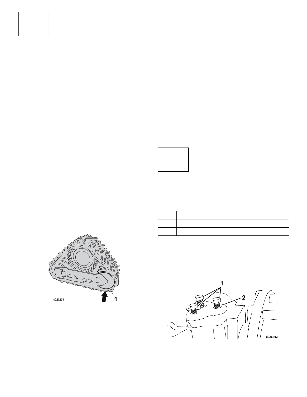
6.Placeafootlong2x4underthereartrackidleronthe
frontaxle(Figure1).
Note:Wheninstallingthekitontherearaxle,place
the2x4underthefronttrackidler.
Important:Useajackstandthatcanholda
capacityof26,000pounds.
5.Supporttheweightofthedrivehub.
6.Removethewheelassembly;refertotheOperator’s
Manualforthemachine.
Note:Ifyourmachineisequippedwithabackhoe,unlock
androtatethewalkwayoutoftheway;refertotheOperator’s
Manualfortheattachment.
2
InstallingtheSteeringSensor
Assembly
Partsneededforthisprocedure:
2
Steeringsensorassembly
2
Screw
2Nut
Figure1
1.Reartrackidler
7.Lowerthemachineuntilthetracksmakecontactwith
thegroundandthereisnoloadonthekingpin.
Note:Themachinewillbesupportedbytheground
andthe2x4.
Procedure
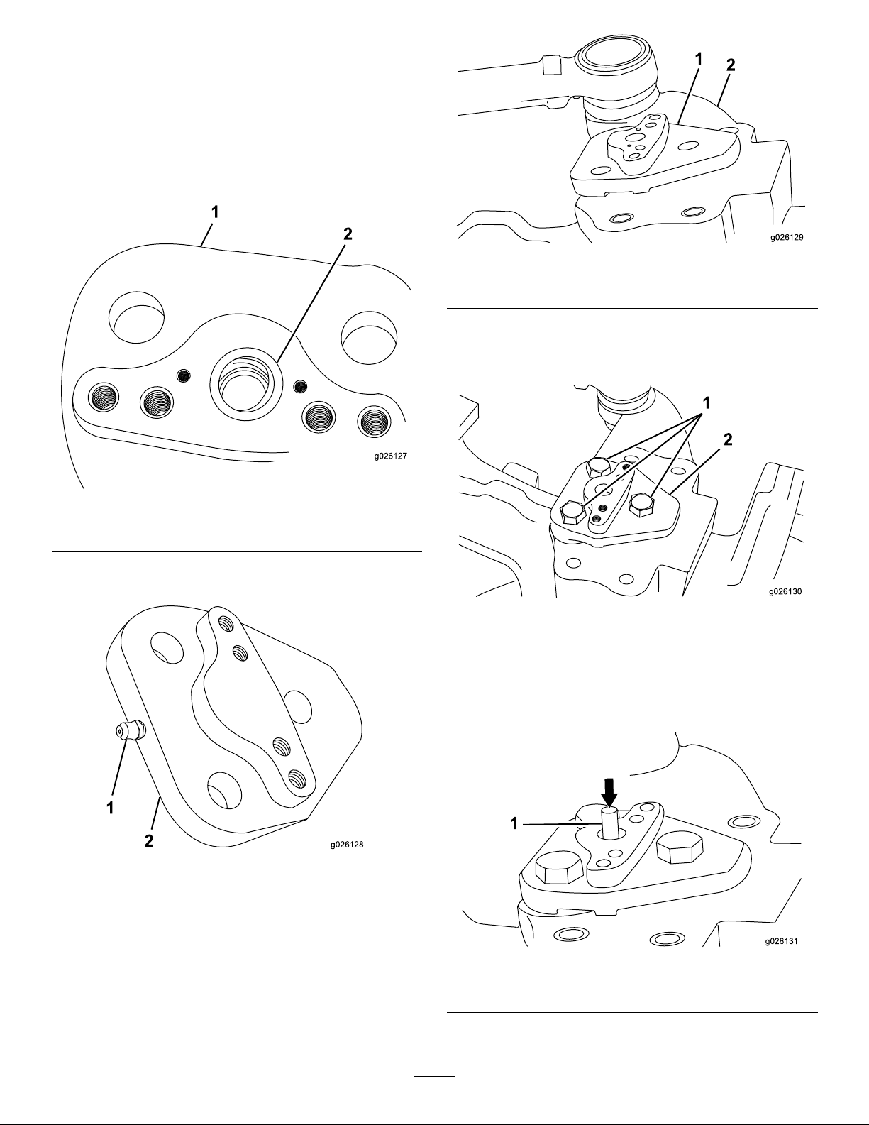
1.Removethe3boltssecuringthetriangularkingpin
fromthetopoftheaxle(Figure2).
Note:Donotdiscardthehardware.
Figure2
1.Hexbolt2.Kingpin
2
Page 3
2.Supportthehubtokeepitfrommoving,thenremove
2
1
g026127
1
2
g026128
1
2
g026129
1
2
g026130
1
g026131
thekingpin.
Note:Thekingpinwillnotbereused.
3.LubricatetheO-ringandinsertitintothegrooveon
thenewkingpin.
Note:Useasmallscrewdriverorsimilartooltoensure
thattheO-ringisinsertedintothegroovedslot(Figure
3).
Figure5
1.Kingpin2.Axlehousing
7.Putathread-lockingcompoundonthe3boltsremoved
earlierandusethemtosecurethenewkingpin(Figure
6).
Figure3
1.Kingpin
2.O-ring
4.Installthegreasettingintothenewkingpin(Figure
4).
Figure4
1.Greasetting
2.Kingpin
Figure6
1.Hexbolt2.Kingpin
8.Inserttheactuatorpinintothekingpin(Figure7).
Note:Donotpushtheactuatorpininalltheway .
5.Putgreaseinthecenterholeandonthesurfaceofthe
kingpin.
6.Insertthenewkingpinintotheaxlehousing.
Note:Ifthehubwassecured,thekingpinshould
1.Actuatorpin
Figure7
installeasily;otherwiseyoumayhavetomovethehub
slightlytoaligntheholes(Figure5).
3
Page 4
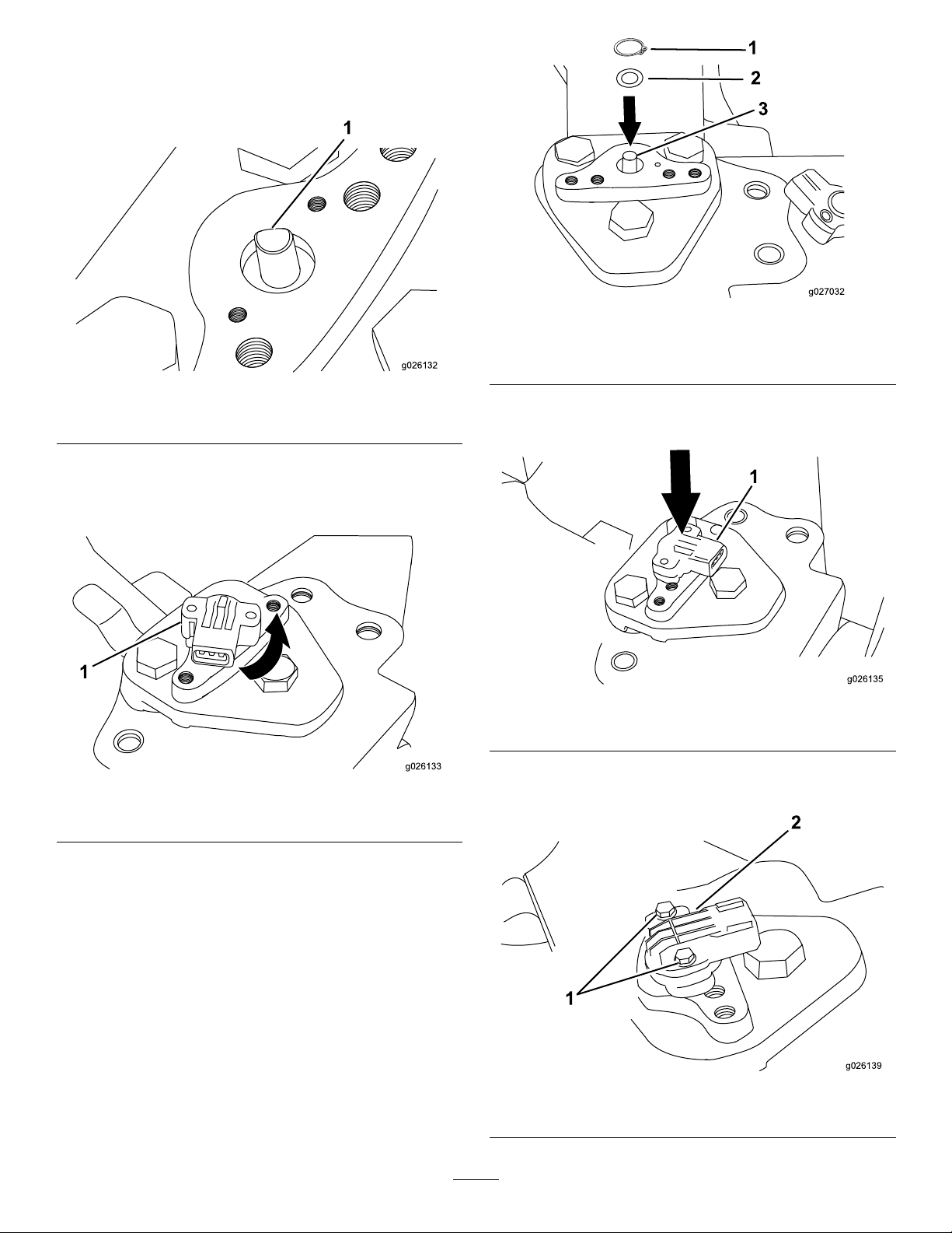
9.Turntheatsideoftheactuatorpintowardthe
1
g026132
1
g026133
1
3
g027032
2
1
g026135
1
2
g026139
machinetoa45-degreeangle(Figure8).
Note:Donotpushtheactuatorpininalltheway .
Figure10
Figure8
1.Flatsideofactuatorpin
10.Placethesensorontotheactuatorpin(Figure9).
Note:Itshouldrotateanequalamountofdegreesin
bothdirections.
Figure9
1.Sensor
1.Snapring
2.Washer
3.Actuatorpin
13.Installthesensorandalignitstraightwiththeoutside
ofthewheelhubwiththemountingholes(Figure11).
Figure11
1.Sensor
14.Securethesensorwith2washersand2hexbolts
(Figure12).
11.Whentheactuatorisorientedtoa45degreeangleto
theaxleasshowninFigure9,removethesensorand
gentlytapontheactuatorpinuntilitisfullyseated.
12.Inserttheatwasherontotheactuatorpin,theninsert
thesnapringontotheactuatorpin(Figure10).
Note:Useasmallscrewdriverorsimilartooltoensure
thesnapringisfullyseatedinthegroove.
Note:Checktomakesurethattheactuatorpinisfully
seatedbypullingonitwithapairofpliers.Itshould
notcomeout.
Figure12
1.Hexbolt
2.Sensor
4
Page 5
15.Plugtheconnectorofthesteeringsensorintothe
1
2
3
g026136
1
2
g026137
1
2
g026138
1
g026140
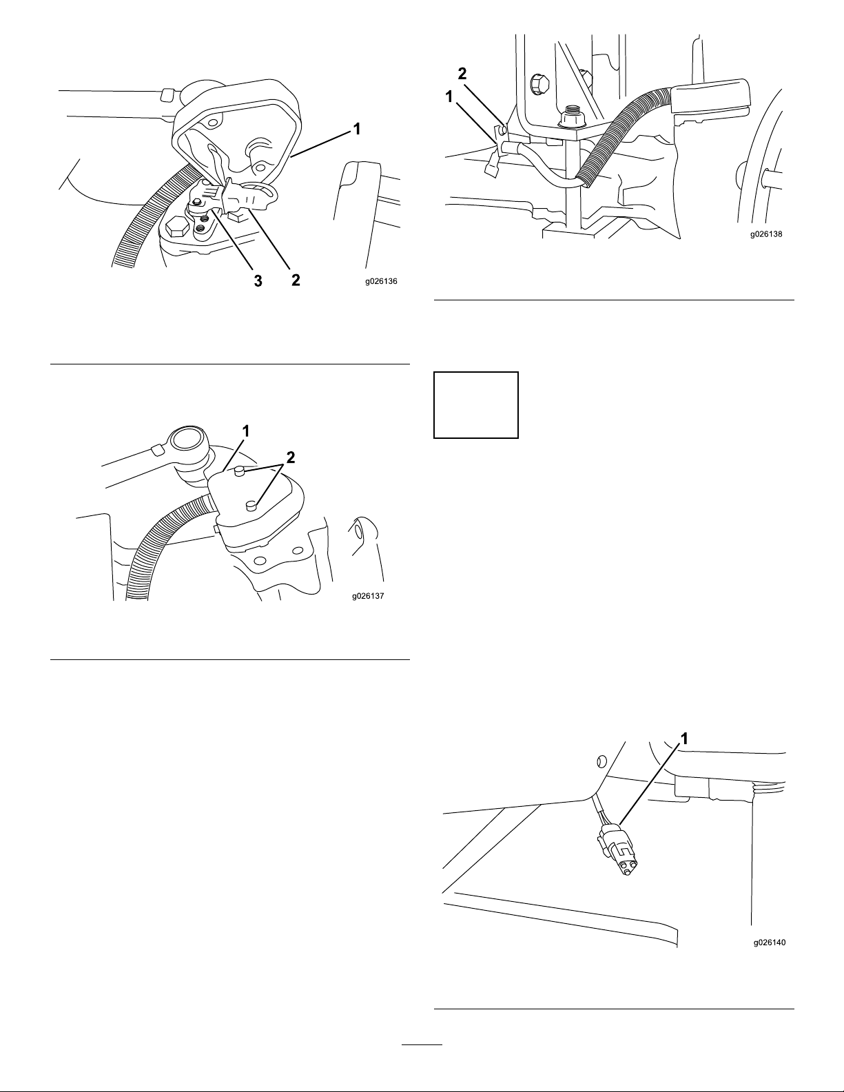
wiringharnessofthecoverassembly(Figure13).
Figure13
1.Sensor3.Cover
2.Wiringharness
16.Aligntheholesandsecurethecoverassemblyusing2
bolts(Figure4).
Figure15
1.Bolt,washerandnut2.Bracket
18.Repeattheproceduresfrom1PreparingtheMachine
(page2)and2InstallingtheSteeringSensorAssembly
(page2)fortherearrightsideofthemachine.
3
Figure14
1.Cover
17.Securethesteeringsensorcabletothechassisframe
withthebracket(Figure15).
Note:Placetheboltontheoutsideoftheframewith
thebracket,withthewasherandnutinsidethechassis
frame.
2.Bolt
ConnectingtheSteering
SensorAssembly
NoPartsRequired
Procedure
1.Plugthesteeringsensorconnectorintotheright-rear
wheelsteeringsensor(Figure16).
Note:Thesteeringsensorconnectorispartofthe
existingwiringharness.Theconnectorislocatedunder
themachine,alongthechassis,abovetheaxle,andnear
theright-rearwheel.
Note:Thesteeringsensorconnectorontheright-rear
sideofthemachineislabeledP45.
Figure16
1.SteeringsensorconnectorP45
5
Page 6
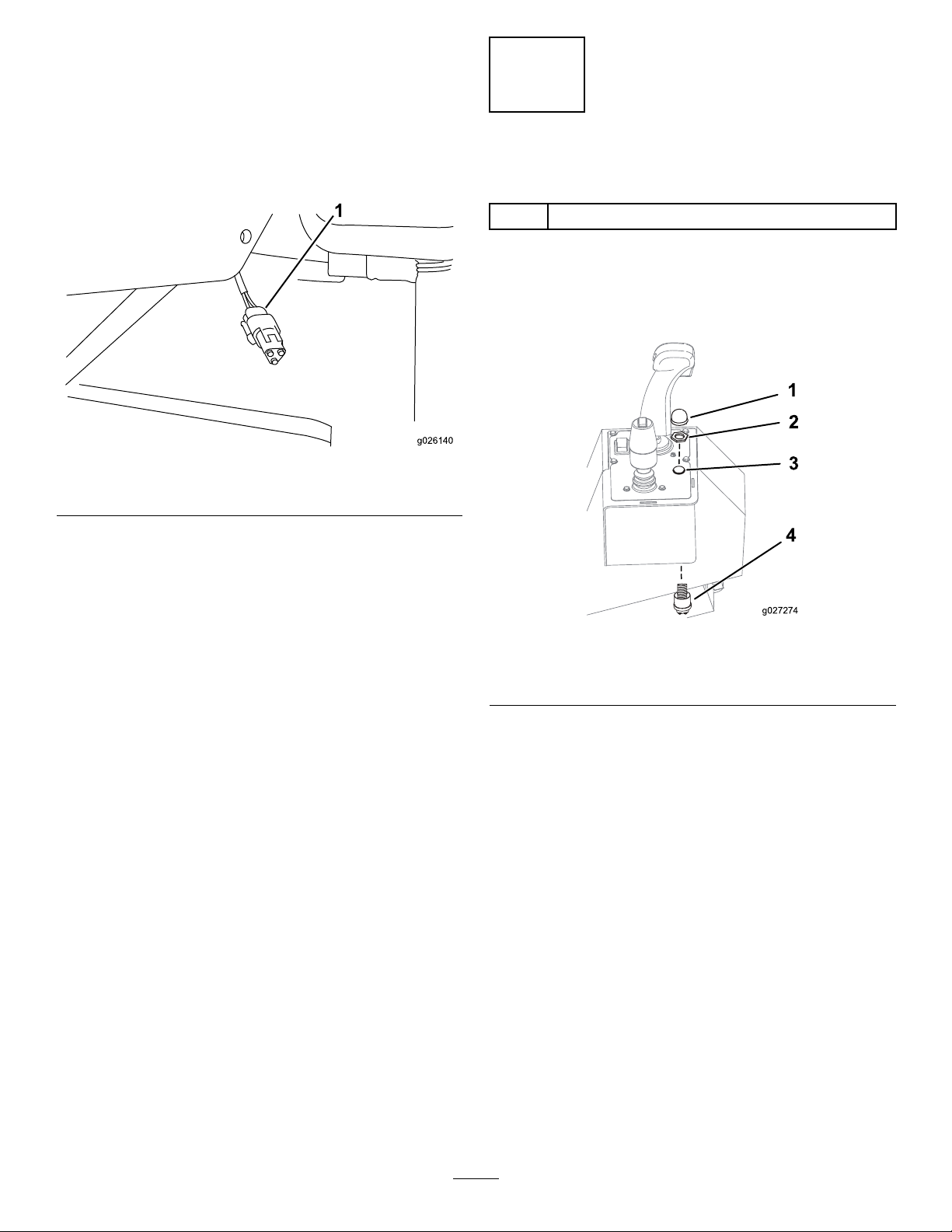
2.Thefrontleftsteeringsensorconnectoristiedoffto
1
g026140
1
2
3
4
g027274
thewiringharness(Figure17).
Note:Routetheharnessdownbehindthechassis
framebytheaxleandconnectthefrontleftwheel
steeringsensor.
Note:Thesteeringsensorontheright-rearsideof
themachineislabeledP07.
Figure17
1.SteeringsensorconnectorP07
Formachineswithtracks.
4
InstallingtheSwitch
Partsneededforthisprocedure:
1
Switchassembly
Procedure
1.Removetheplugonthecontrolpanelontheleft-side
oftheseat(Figure18).
1.Jackuptherearrightsideofthemachineandremove
the2x4underthetracks.
Note:Repeatforthefrontleftsideofthemachineif
that2x4hasnotalreadybeenremoved.
2.Lowerthemachinesothatthemachineisonthe
ground.
Formachineswithwheels.
1.Installthetireassemblyusingthelugnutsandwashers
previouslyremoved.
2.Torquethelugnuts;refertotheOperator’sManualfor
themachine.
3.Repeattheentireprocessforthefront-leftwheel.
4.Fillbothkingpinswithgreaseuntilgreasejustbegins
toowoutaroundthegreasetting.
5.Lowerthemachinetotheground.
Forallmachines.
1.MovethemasterdisconnectswitchtotheOnposition.
2.TurntheignitionkeytotheOnposition.
Figure18
1.Rubberbutton3.Plug
2.Hexnut
2.Insertthebottompartoftheswitchassembly
underneaththecontrolpanelupthroughthehole
wheretheplugwaslocated(Figure18).
3.Securethebottomswitchassemblyusingthehexnut
andtherubberbutton(Figure18).
4.Locatethe2availablewiresconnectedtotheexisting
wiringharnessunderthecontrolpanelcoveronthe
left-sideoftheseat.
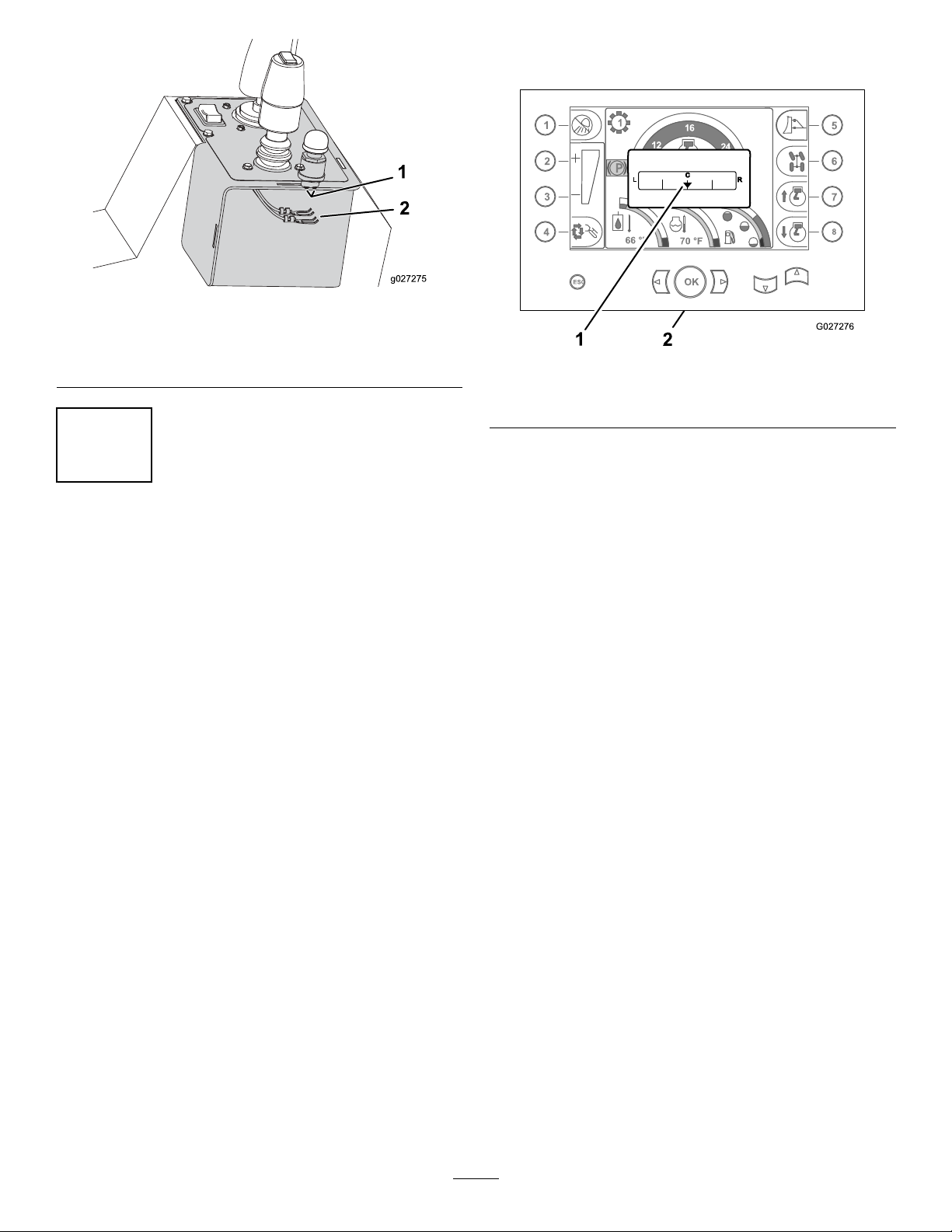
5.Loosentheboltsatthebottomoftheswitchassembly ,
placetheterminalssothatthebodyoftheboltisin
betweenthe2prongs,andtightenthebolts(Figure19).
4.Switch
Note:Theinstrumentpaneldisplayshouldnothave
aniconbybutton6.
3.TurntheignitionkeytotheOffposition.
6
Page 7
1
2
g027275
Figure19
1
P
0
RPM
0
%
LOAD
66 °F
70 °F
6
12
16
24
30
1
2
3
4
5
6
7
8
ESC
OK
G027276
1
2
L
C
R
Note:Thesteeringmodeshouldautomaticallychange
tofrontsteering.
1.Boltsonthebottomofthe
switchassembly(located
inthecoverassembly)
2.Terminalsonthewiring
harness(locatedinthe
coverassembly)
5
CalibratingandTestingthe
Machine
NoPartsRequired
Procedure
1.Starttheengineandcenterthefrontandrearwheels.
2.Pressthedownarrowtogettothemenuandpress
button2,TrencherSetup.
Note:YouwillneedaPINtoaccessthisscreen;
toobtainthePIN,contactanAuthorizedT oro
Distributor.
3.EnterPINnumberandpressOK.
4.SelectSteeringCalibration.
5.Followtheon-screendirectionstocalibratethesteering.
6.ExittothemainscreenusingtheEscbutton.
7.Setthesteeringmodetocrabsteering.
1.Rearwheelposition
indicator
Figure20
2.Commandcenterscreen
Note:Therearwheelsshouldmatchtheangleofthe
frontwheels.
8.Rotatethesteeringwheel.
Note:Therearwheelsshouldcontinuetofollowthe
angleofthefrontwheels.
9.Changethesteeringmodetocoordinatedsteering.
Note:Therearwheelsshouldturnintheopposite
directionofthefrontwheels.
10.Pushandholdtherearsteercenteringbuttonuntilthe
indicatorontheshowsthattherearwheelsarestraight.
7
Page 8

 Loading...