

Page 1
Auto-TiltChassis
RT1200TractionUnit
ModelNo.25511
ModelNo.25511E
ThisproductcontainsachemicalorchemicalsknowntotheStateofCaliforniato
causecancer,birthdefects,orreproductiveharm.
LooseParts
Usethechartbelowtoverifythatallpartshavebeenshipped.
FormNo.3383-980RevA
InstallationInstructions
WARNING
CALIFORNIA
Proposition65Warning
Description
Tiltsensor1
Bolt2
Locknut2
Rockerswitch1
Nopartsrequired
InstallingtheAuto-tiltChassis
1.Removethefourboltssecuringthefootplatetothe
frameandremovetheplate(Figure1).
Qty.
Use
Installtheauto-tiltchassis.
–
Calibratethesensor.
Figure2
1.Tiltsensor2.Bolts
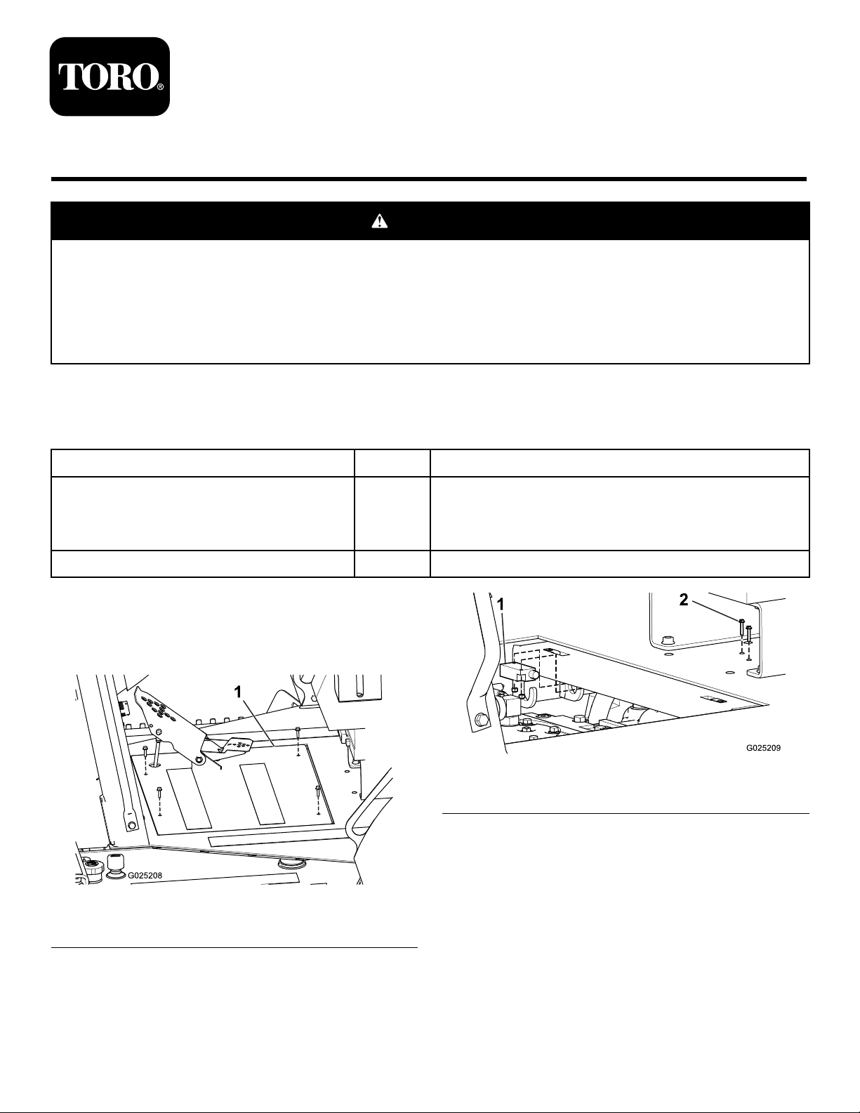
4.Connectthesensortotheopenconnectorfromthe
mainwireharnessasshownin
Figure3.
Figure1
1.Footplate
2.Disconnectthewireharnessfromthefoot-pedal
sensorandsettheoorplateaside.
3.Installthetiltsensorundertheoorundertheseat
using2boltsandlocknuts(Figure2).
©2014—TheToro®Company
8111LyndaleAvenueSouth
Bloomington,MN55420
Registeratwww.T oro.com.
OriginalInstructions(EN)
PrintedintheUSA
AllRightsReserved
*3383-980*A
Page 2
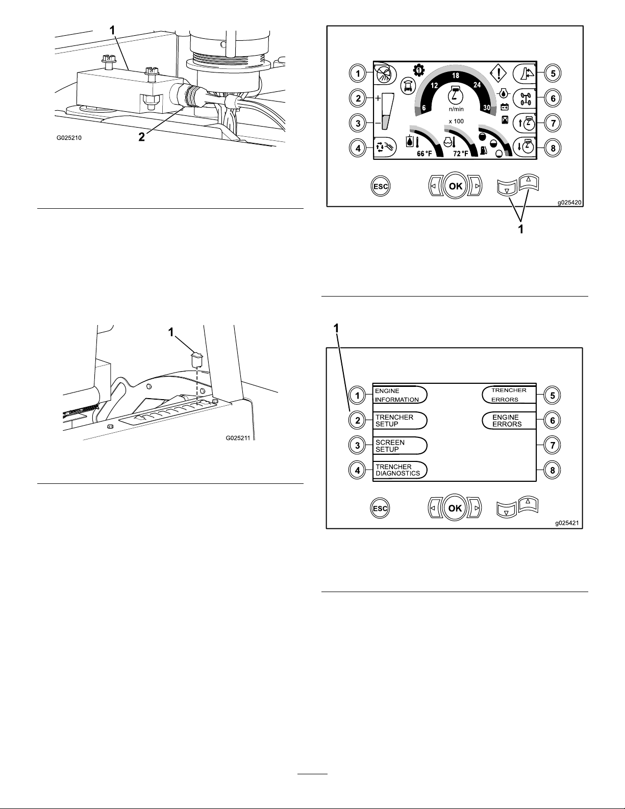
Figure3
(Floorremovedforillustrativepurposes)
1.Tiltsensor2.Wiring-harnessconnector
5.Connectthewireharnessyoudisconnectedinstep2
tothefoot-pedalsensor.
6.Installthefootplate,securingitwiththe4bolts
removedpreviously,andconnectthefootpedaltothe
drivelinkage.
7.Removetheplugfromthesecondswitchpositionfrom
therightonthecontrolpanelbehindtheseat(Figure4).
Figure4
Figure5
HomeScreen
1.Upanddownarrowkeys
Thediagnosticscreen(Figure6)displays.
1.Rockerswitch
8.Removetheswitchconnectorfromtheplugand
connectittothenewrockerswitch.
9.Installtherockerswitchintotheopenslot,ensuring
thatitseatsintotheconnectorundertheswitchplate
(Figure4).
CalibratingtheSensor
1.Starttheengineandmovethemachinetolevelground.
2.FromtheHomescreen,pressandholdtheupand
downarrowkeys(
Figure5).
Figure6
DiagnosticScreen
1.Trenchersetupbutton
3.Press2toselectTrencherSetup(Figure6).
ThePINentryscreendisplays.
4.Enteryour8-digitPIN.Ifyoudonothaveaservice
PINforyourmachine,contactyourAuthorizedService
Dealer.
TheTrencherSetupscreenappears(
Figure7).
2
Page 3

8.Usethetoggleswitchtoreturnthemachinetothelevel
position.
9.Pressbutton2toselectSetCenter(Figure8)and
waitunitthecenterindicatorlightturnsgreen
(approximately10seconds).
10.Usethetoggleswitchtotiltthemachinetothefull
rightposition.
Figure7
TrencherSetupScreen
1.AutotiltSetupbutton
5.Press2toselectAutotiltSetup(Figure7).
TheAutotiltSetupScreendisplays(Figure8).
11.Pressandholdbutton3toselectSetRight(
Figure
8)andwaitunittherightindicatorlightturnsgreen
(approximately10seconds).
12.Returnthemachinetothelevelposition.
13.Press4toselectExitwhentheindicatorlightnextto
theExitbuttonturnsgreen(Figure8).
Note:Youcannotexitthisscreenuntilallthreepositions
havebeenset.Shouldyouneedtoexitwithoutcompleting
thesetup,turnoffthekeyswitch.
Operation
WhentheswitchisintheOnposition,theAuto-tiltChassis
featurekeepsthechassisnearlevelasyoudrivethemachine.
TurnofftheAuto-tiltswitchtoreturntomanualchassis-tilt
operation.
Figure8
AutotiltSetupScreen
1.SetLeftbutton
2.SetCenterbutton
3.SetRightbutton
4.Exitbutton
5.Machineiconwithindicator
lights
6.Usingthemanualtilttoggleswitch,locatedontherear
consoleofthemachine,tiltthemachinetothefullleft
position.
7.Pressbutton1toselectSetLeft(Figure8)andwait
unittheleftindicatorlightturnsgreen(approximately
10seconds).
3
Page 4

 Loading...