

Page 1
FormNo.3395-883RevA
RT1200TractionUnit
ModelNo.25500—SerialNo.315000001andUp
ModelNo.25500A—SerialNo.315000001andUp
ModelNo.25500C—SerialNo.315000001andUp
ModelNo.25500W—SerialNo.315000001andUp
Registeratwww.T oro.com.
OriginalInstructions(EN)
*3395-883*A
Page 2
WARNING
CALIFORNIA
Proposition65Warning
ThisproductcontainsachemicalorchemicalsknowntotheStateofCaliforniato
causecancer,birthdefects,orreproductiveharm.
DieselengineexhaustandsomeofitsconstituentsareknowntotheStateofCalifornia
tocausecancer,birthdefects,andotherreproductiveharm.
Becauseinsomeareastherearelocal,state,orfederal
regulationsrequiringthatasparkarresterbeusedonthe
engineofthismachine,asparkarresterisavailableas
anoption.Ifyourequireasparkarrester,contactyour
AuthorizedToroServiceDealer.
SparkarrestersrecommendedbyToroforthisproductare
USDAForestryapproved.
Important:Thisengineisnotequippedwithaspark
arrestermufer.ItisaviolationofCaliforniaPublic
ResourceCodeSection4442touseoroperatetheengine
Introduction
Thismachineisdesignedtodigtrenchesinsoiltobury
cablingandpipingforvariousapplications.Itisnotintended
tocutanyothermaterialotherthansoilandrock.
Readthisinformationcarefullytolearnhowtooperateand
maintainyourproductproperlyandtoavoidinjuryand
productdamage.Youareresponsibleforoperatingthe
productproperlyandsafely.
onanyforest-covered,brush-covered,orgrass-covered
land.Otherstatesorfederalareasmayhavesimilarlaws.
Theenclosed
Engine Owner's Man ual
issuppliedfor
informationregardingtheUSEnvironmentalProtection
Agency(EPA)andtheCaliforniaEmissionControl
Regulationofemissionsystems,maintenance,and
warranty.Replacementsmaybeorderedthroughthe
enginemanufacturer.
YoumaycontactTorodirectlyatwww .Toro.comforproduct
safetyandoperationtrainingmaterials,accessoryinformation,
helpndingadealer,ortoregisteryourproduct.
Wheneveryouneedservice,genuineT oroparts,oradditional
information,contactanAuthorizedToroServiceDealer
orToroCustomerServiceandhavethemodelandserial
numbersofyourproductready.Figure1illustratesthe
locationofthemodelandserialnumbersontheproduct.
Writethenumbersinthespaceprovided.
Figure1
1.Locationofthemodelandserialnumberplate
ModelNo.
SerialNo.
Thismanualidentiespotentialhazardsandhassafety
messagesidentiedbythesafetyalertsymbol(Figure2),
whichsignalsahazardthatmaycauseseriousinjuryordeath
ifyoudonotfollowtherecommendedprecautions.
©2015—TheToro®Company
8111LyndaleAvenueSouth
Bloomington,MN55420
Contactusatwww.Toro.com.
2
PrintedintheUSA
AllRightsReserved
Page 3
Contents
Figure2
1.Safetyalertsymbol
Thismanualuses2wordstohighlightinformation.
Importantcallsattentiontospecialmechanicalinformation
andNoteemphasizesgeneralinformationworthyofspecial
attention.
StorethisOperator’ sManualandtheengineowners’smanualin
themanualcompartmentthatisequippedwiththismachine.
Figure3
1.Manualcompartment
Safety...........................................................................4
............................................................................5
ElectricalLineSafety...............................................7
GasLineSafety.......................................................7
CommunicationLineSafety......................................7
WaterLineSafety....................................................7
SafetyandInstructionalDecals.................................8
ProductOverview.........................................................15
Controls...............................................................15
CommandCenter...............................................15
MachineControls...............................................16
Traction-ControlCluster.....................................17
Attachment-ControlCluster.................................17
OperatorSeatandSeatBelt.................................19
Specications........................................................20
Attachments/Accessories........................................20
Operation....................................................................21
ThinkSafetyFirst...................................................21
PreparingforWork.................................................21
AddingFueltotheEngine.......................................21
CheckingtheEngine-OilLevel.................................24
CheckingtheCoolantLevelintheReservoir...............25
CheckingtheHydraulic-FluidLevel..........................25
CheckingtheRestrictedAir-CleanerIndicator............26
InspectingtheMachine...........................................26
OperatingtheCommandCenter...............................26
OperatingtheEngine..............................................33
OperatingtheMachineinExtreme
Conditions.........................................................34
OperatingtheParkingBrake....................................35
DrivingandStoppingtheMachine............................35
OperatingtheTransmission.....................................37
OperatingtheMachineTiltFeature...........................37
PreparingtoOperatetheMachine.............................38
UsingthePowerPort..............................................39
TransportingtheMachine........................................39
CompletingtheWorkfortheDay.............................40
CompletingtheProject...........................................40
Maintenance.................................................................41
RecommendedMaintenanceSchedule(s)......................41
PremaintenanceProcedures........................................42
GeneralSafety........................................................42
Lubrication...............................................................42
GreasingtheMachine.............................................42
EngineMaintenance..................................................44
AccessingtheEngine..............................................44
ServicingtheEngineOilandFilter............................45
CheckingtheCrankcaseBreatherTube......................47
CheckingtheCharge-airPiping................................47
ServicingtheAir-cleanerSystem...............................47
FuelSystemMaintenance...........................................49
ServicingtheFuelSystem........................................49
ElectricalSystemMaintenance....................................52
MaintainingtheBattery...........................................52
ReplacingaFuse.....................................................54
DriveSystemMaintenance.........................................55
3
Page 4

ServicingtheTires..................................................55
ServicingtheAxles.................................................56
ServicingtheTransmission......................................60
CoolingSystemMaintenance......................................63
ServicingtheCoolingSystem...................................63
BeltMaintenance......................................................67
ServicingtheEngineDriveBelt................................67
ReplacingtheEngineDriveBelt...............................67
HydraulicSystemMaintenance....................................68
ServicingtheHydraulicSystem.................................68
ROPSMaintenance....................................................72
CheckingandServicingtheROPS.............................72
WeldingontheMachine..............................................73
PreparingtoDisconnecttheComponents..................73
DisconnectingtheAlternatorWiring.........................74
DisconnectingtheComputer-module
Connectors........................................................74
ConnectingtheComputer-module
Connectors........................................................74
ConnectingtheAlternatorWiring.............................75
ClosingtheMachine...............................................75
Cleaning...................................................................75
RemovingDirtandDebrisfromtheMachine.............75
Storage........................................................................76
PreparingforSeasonalStorage.................................76
Troubleshooting...........................................................77
Safety
Improperlyusingormaintainingthismachinecan
resultininjury.Toreducethepotentialforinjury,comply
withthesesafetyinstructionsandalwayspayattentionto
thesafetyalertsymbol(Figure2),whichmeansCaution,
Warning,orDanger—personalsafetyinstruction.Failure
tocomplywiththeinstructionmayresultinpersonal
injuryordeath.
Important:Thismachinewasmanufacturedaccording
totheappropriateregulatorystandardsineffectatthe
timeofmanufacture.Modifyingthismachineinany
waymaycauseittobeoutofcompliancewiththose
standardsandwiththeinstructionsinthis
Man ual.
onlybyanAuthorizedT oroServiceDealer.
Modicationstothismachineshouldbemade
WARNING
Welding,cutting,ordrillingpartsofthemachine
couldcausethemtobreakduringoperation,which
inturncouldresultininjuryordeath.
Donotweld,cut,ordrilltorepairortoattachitems
topartsonthismachine.
Operator’ s
Alwaysfollowallsafetyinstructionstoavoidseriousinjury
ordeath.
Youcanpreventandareresponsibleforinjuriesoccurringto
yourselfandtoothersandfordamagetoproperty.
Donotusethismachineforapplicationsotherthanthose
whicharedescribedinthismanual.
Beforeoperatingthismachine,itisyourresponsibilityto
knowwhereallutilitylinesareburiedintheprojectareaand
toavoidthem.
Alwaysensurethatalllocalutilitycompaniesmark
thelocationoftheirlines.IntheUSAandCanada,
calla“One-callSystemDirectory”service.Inthe
USA,call811oryourlocalnumber.Ifyoudonotknow
yourlocalnumber,callthenationalnumber(USAand
Canadaonly)at1-888-258-0808.Also,contactanyutility
companiesthatarenotparticipantsofthe“One-call
SystemDirectory”service.
Checkwithlocalauthoritiesforalllawsandregulationsthat
requireyoutolocateandavoidexistingutilities.
Refertothefollowingtablefortheproperutilitylineandthe
correspondingutilitylinecolor(USAandCanadaonly):
4
Page 5

UtilityLine
ElectricRed
Telecommunication,alarmorsignal,cables,
orconduit
Naturalgas,oil,steam,petroleum,orother
gaseousorammablematerial
SeweranddrainGreen
DrinkingwaterBlue
Reclaimedwater,irrigation,andslurrylinesPurple
TemporarysurveymarkingsPink
ProposedexcavationlimitsWhite
Afterlocatingalltheutilitylines,carefullydigaholetothe
utilitylinebyhandtoverifythelocationandthedepthof
theline.
Color
Orange
Yellow
•Beforeoperatingthemachinewithanattachment,ensure
thattheattachmentisproperlyinstalled.
•Useextracarewhenhandlingfuels.Theyareammable
andvaporsareexplosive.
–Useonlyanapprovedcontainer.
–Donotremovethefuelcaporaddfuelwiththe
enginerunning.Allowtheenginetocoolbefore
fueling.Donotsmokenearthemachinewhilethe
engineisrunning.
–Donotrefuelordrainthemachineindoors.
•Checkthattheoperator'spresencecontrols,safety
switches,andshieldsareattachedandfunctioning
properly.Donotoperatethemachineunlessthese
controls,switches,andshieldsarefunctioningproperly.
GeneralOperation
•Alwaysweartheseatbeltwhenoperatingthismachine.
Training
•ReadtheOperator'sManualandothertrainingmaterial.If
theoperator(s)ormechanic(s)cannotreadEnglish,itis
theowner'sresponsibilitytoexplainthismaterialtothem.
•Becomefamiliarwiththesafeoperationoftheequipment,
operatorcontrols,andsafetysigns.
•Alloperatorsandmechanicsmustbetrained.Theowner
isresponsiblefortrainingtheusers.
•Neverletchildrenoruntrainedpeopleoperateorservice
themachine.Localregulationsmayrestricttheageof
theoperator.
•Ensurethatyouunderstandthehandsignalsusedonthe
jobsite.Followtheinstructionsofthesignalperson.
Preparation
•Beforeusingthemachine,havetheareamarkedfor
undergroundutilities,anddonotdiginmarkedareas.
Also,beawareofthelocationofobjectsandstructures
thatmaynotbemarked,suchasundergroundstorage
tanks,wells,andsepticsystems.
•Evaluatetheterraintodeterminewhataccessoriesand
attachmentsareneededtoproperlyandsafelyperform
thejob.Useonlyaccessoriesandattachmentsapproved
bythemanufacturer.
•Markthejobsiteclearlyandkeepbystandersaway.
•Reviewthejobsitehazards,safetyandemergency
procedures,andpersonnelresponsibilitieswithall
workersbeforebeginningthework.
•Wearappropriateclothing,includinghardhat,safety
glasses,longpants,safetyshoes,andhearingprotection;
somejobsmayalsorequirethatyouwearareectivevest
and/orarespirator.Securelonghair,looseclothing,and
jewelrytopreventthemfromgettingtangledinmoving
parts.
•Donotruntheengineinanenclosedarea.
•Donotoperatethemachinewithoutalloftheguards
andpanelssecurelyinplace.Ensurethatallinterlocksare
attached,adjustedcorrectly,andfunctioningproperly.
•Decreasethegroundspeedofthemachineanduse
cautionwhenmakingturnsandcrossingroadsandrough
oruneventerrain.
•Donotoperatethemachinewhileundertheinuence
ofalcoholordrugs.
•Ensurethattheareaisclearofotherpeoplebefore
operatingthemachine.Stopthemachineifanyoneenters
thearea.
•Excessivevibrationfromatrencheroraplowcancausea
trench,anoverhang,orahighbanktocollapse,resulting
inpossibleinjuryordeath.
•Ifyourviewoftheworkareaisnotclear,alwayshavea
signalpersondirectthemovementofthemachine.
•Donotleavearunningmachineunattended.Stopthe
engineandremovethekeywheneveryouleavethe
machine.
•UseonlyToro-approvedattachments.Attachmentscan
changethestabilityandtheoperatingcharacteristicsof
themachine.
•Watchfortrafcwhenoperatingthemachinenearor
acrossroadways.
•Onlyoperatethemachineinareaswherethereareno
obstaclesincloseproximitytoyou.Failuretomaintain
anadequatedistancefromtrees,walls,andotherbarriers
whileoperatingthemachinemayresultininjuryand/or
damage.Operatethemachineonlyinareaswherethere
issufcientclearanceforyoutosafelymaneuverthe
machine.
5
Page 6

•Locatethepinchpointareasthataremarkedonthe
machineandattachments;keephandsandfeetawayfrom
theseareas.
•Lightningcancausesevereinjuryordeath.Iflightning
isseenorthunderisheardinthearea,donotoperate
themachine;seekshelter.
SlopeOperation
•Avoidoperatingthismachineonslopes,ifpossible.
•Keepallmovementsonslopesslowandgradual.Donot
makesuddenchangesinspeedordirection.
•Avoidstartingorstoppingthemachineonaslope.Ifthe
machinelosestraction,keeptheheavyendofthemachine
uphillandproceedslowly,straightdowntheslope.
•Avoidturningthemachineonslopes.Ifyoumustturn,
turnslowlyandkeeptheheavyendofthemachineuphill.
•Donotoperatethemachineneardrop-offs,ditches,or
embankments.Themachinecouldsuddenlyturnoverif
atireortrackgoesovertheedgeofaclifforditch,orif
anedgecavesin.
RolloverProtectionStructure(ROPS)
System
•Beforeoperatingthemachine,ensurethattheseatbeltis
ingoodconditionandissecurelyattachedtothemachine.
•InspecttheROPSattheintervalrecommendedinthis
manualorwhentheROPShasbeeninanaccident.
•ReplaceadamagedROPSusingonlygenuineToro
replacementparts;donotrepairormodifytheROPS.
•Checkcarefullyforoverheadclearances(i.e.branches,
doorways,electricalwires)beforedrivingunderany
objects,anddonotcontactthem.
•DonotremovetheROPSexceptwhenreplacingit.
•Donotaddweighttothemachinethatexceedsthegross
weightdisplayedontheROPSlabel.
TransportingSafety
Whenyoutransportthemachinetoorfromthejobsite,
observethefollowingsafetyprecautions:
•Donotcarrypassengersonthemachine.
•Keepallbystandersawaywhileyouaremovingthe
machine.
•Usecarewhenloadingorunloadingthemachineintoa
trailerortruck.
•Watchfortrafcwhenyouarecrossingroadwayswith
themachine.
•Checkforoverheadclearances(i.e.,branches,doorways,
electricalwires)beforedrivingunderanyobjects,anddo
notcontactthem.
MaintenanceandStorage
•Lowertheattachment(s),stoptheengine,waitforall
movingpartstostop,andremovethekeywheneveryou
adjust,clean,orrepairthemachine.
•Donottouchpartsthatmaybehotfromoperation.
Allowthemtocoolbeforeattemptingtomaintain,adjust,
orservicethemachine.
•Cleandebrisfromallattachments,drives,mufers,and
theenginetohelppreventres.Cleanupoilandfuel
spills.
•Lettheenginecoolbeforestoringthemachine,anddo
notstoreitnearanopename.
•Parkthemachineonlevelground.
•Donotallowuntrainedpersonneltoservicethemachine.
•Usejackstandstosupportcomponentswhenrequired.
•Carefullyreleasepressurefromcomponentswithstored
energy.
•Keephandsandfeetawayfrommovingparts.Ifpossible,
donotmakeadjustmentswiththeenginerunning.
•Keepallpartsingoodworkingconditionandallhardware
tightened.Replaceallwornordamageddecals.
•Keepnutsandboltstight.Keepallequipmentingood
condition.
•Donottamperwithsafetydevices.
•Useextracarewhenhandlingfuels.Theyareammable
andvaporsareexplosive.
–Useonlyanapprovedcontainer.
–Donotremovethefuelcaporaddfuelwhenthe
engineisrunning.Allowtheenginetocoolbefore
refueling.Donotsmokewhilefuelingthemachine.
–Donotrefuelthemachineindoors.
–Donotdrainthefuelindoors.
–Donotstorethemachineorafuelcontainerinside
wherethereisanopename,suchasnearawater
heaterorfurnace.
–Donotllacontainerwhileitisinsideavehicle,
trunk,pickupbed,oranysurfaceotherthanthe
ground.
–Keepthecontainernozzleincontactwiththetank
duringlling.
•UseonlygenuineTororeplacementparts.
•Disconnectthebatterybeforemakinganyrepairs.
Disconnectfromthenegativebatteryterminalrstand
fromthepositivebatteryterminallast.Connecttothe
positiveterminalrstandtothenegativeterminallast.
•Chargethebatteryinanopen,well-ventilatedarea,
awayfromsparkandames.Unplugthechargerbefore
connectingordisconnectingitfromthebattery.W ear
protectiveclothinganduseinsulatedtools.
•Batteryacidispoisonousandcancauseburns.Avoid
contactwithskin,eyes,andclothing.Protectyourface,
eyes,andclothingwhenworkingwithabattery.
6
Page 7

•Batterygasescanexplode.Keepcigarettes,sparks,and
amesawayfromthebattery.
•Keepyourbodyandhandsawayfrompinholeleaks
ornozzlesthatejecthigh-pressurehydraulicuid.Use
cardboardorpapertondhydraulicleaks;neveruse
yourhands.Hydraulicuidescapingunderpressurecan
penetrateskinandcauseinjury,requiringsurgerywithin
afewhoursbyaqualiedsurgeon;otherwise,gangrene
mayresult.
GasLineSafety
WARNING
Ifyoudamageagasline,animmediateexplosion
andrehazardcouldoccur.Leakinggasisboth
ammableandexplosiveandmaycauseserious
injuryordeath.
•Allowthemachinetocoolbeforestoringit.
ElectricalLineSafety
WARNING
Ifyouleavetheseatofthemachineortouch
anypartofthemachinewhenitischargedwith
electricity,seriousinjuryordeathcouldresult.
Donotleavetheseatofthemachineifthemachine
ischargedwithelectricity .
Important:Intheeventthemachinebecomes
electricallycharged,immediatelycontacttheproper
emergencyandutilityauthoritiestosecurethearea.
Ifyouareoperatingthemachineanditbecomes
electricallycharged,donotleavetheseatuntilthesource
ofelectricalenergyisremovedfromthemachine.Keep
otherpeopleawayfromthemachineifitiselectrically
charged.
Note:Itispossibletostrikeautilitylinewithoutthemachine
becomingcharged.
•Donotsmokewhileoperatingthemachine.
•Shutoffthemachineandremovethekey.
•Removeallindividualsfromtheworkarea.
•Immediatelycontacttheproperemergencyand
utilityauthoritiestosecurethearea.
CommunicationLineSafety
CAUTION
Ifyoudamagetheberopticcableandlookinto
theexposedhighly-intenselight,youmayharm
youreyes.
•Shutoffthemachineandremovethekey.
•Removeallindividualsfromtheworkarea.
•Immediatelycontacttheproperemergencyand
utilityauthoritiestosecurethearea.
WaterLineSafety
•Itislikely(butnotalwaysthecase)thatthepower-source
interrupterorbreakerwilltrip,buttoensureyoursafety,
alwaysassumethatthemachinemaybeconducting
electricity.
Note:Youwillbesafeaslongasyoudonotleavethe
seatofthemachine.
•Touchinganypartofanelectricallychargedmachinewhile
youareonthegroundmaycauseasevereelectricshock.
Note:Donotallowanotherindividualtotouchor
approachthemachinewhenitischarged.
Ifyoudamageawaterline,apotentialoodhazard
couldoccur.
•Shutoffthemachineandremovethekey .
•Removeallindividualsfromtheworkarea.
•Immediatelycontacttheproperemergencyand
utilityauthoritiestosecurethearea.
7
Page 8
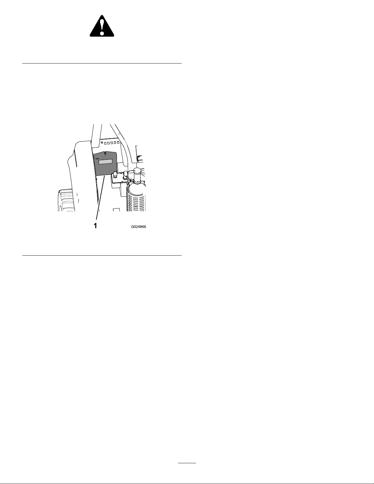
SafetyandInstructionalDecals
Safetydecalsandinstructionsareeasilyvisibletotheoperatorandarelocatednearanyareaofpotential
danger.Replaceanydecalthatisdamagedorlost.
Figure4
1.Decal125-6689
2.Decal125-49638.Decal125-8481
3.Decal125-84799.Decal125-8482
4.Decal125-848010.Decal117-2718
5.Decal125-849911.Decal125-6139
6.Decal125-6135
7.Decal125-6694(2decals,
1oneachside)
Figure5
1.Decal125-84967.Decal125-4963
2.Decal125-8473(onthe
oorpanelcoveringthe
battery)
3.Decal125-84959.Decal125-8480
4.Decal127-1828
5.Decal125-613911.Decal125-8483
6.Decal130-754012.Decal125-6689
10.Decal125-6157(under
Figure6
1.Decal131–04393.Decal125-8484
2.Decal130-75394.Decal131–0440
8.Decal127-1829
theleft-sidecowl)
8
Page 9
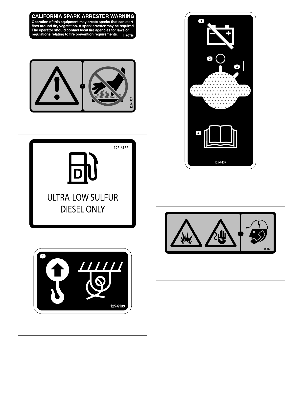
1.Warning—donottouchhotsurfaces.
0000
0000
0000
117-2718
125-4963
125-6157
1.Disconnectthebattery
3.On/Start
power.
2.Off/Stop4.ReadtheOperator’s
Manual.
125–6135
125-6671
1.Explosionhazard;electricshockhazard—calllocalutilities
beforedigging.
125–6139
1.Liftpoint;tiedownpoint
9
Page 10
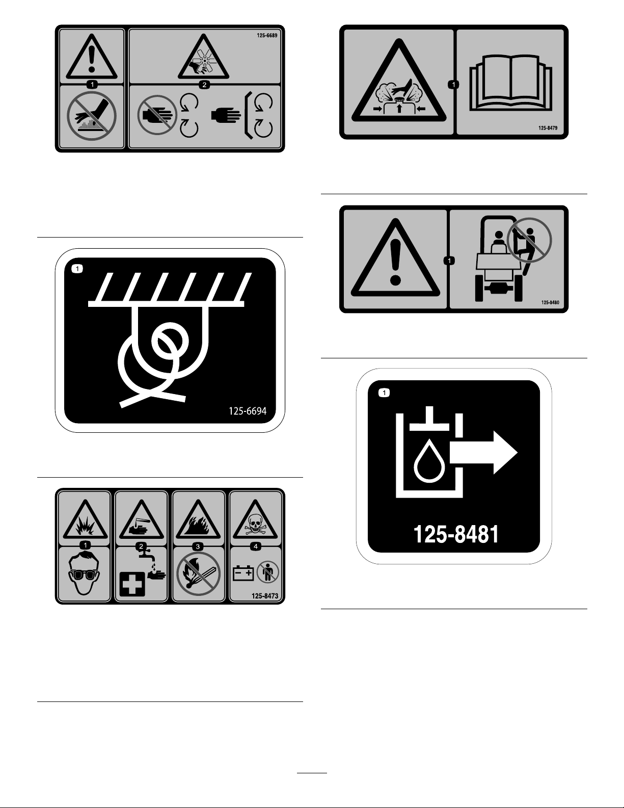
1.Warning—keepawayfrom
hotsurfaces.
125-8479
125-6689
2.Cutting/dismemberment
hazard,fan—keepaway
frommovingparts;keep
allguardsandsafety
devicesinplace.
1.Burnhazardfromcontentsunderpressure—readthe
Operator’sManual.
125-8480
1.Warning—noriders
125-6694
1.Tie-downpoint
1.Explosionhazard—wear
eyeprotection.
2.Causticliquid/chemical
burnhazard—rinse
affectedareaandseek
medicalassistance.
125-8481
1.Hydraulicsupply
125–8473
3.Firehazard—keepopen
amesaway.
4.Poisonhazard—donot
tamperwiththebattery.
10
Page 11
125-8499
125-8482
1.Hydraulicreturn
125–8483
1.Hydraulicuid;readtheOperator’sManual.
1.Warning—readthe
Operator'sManual.
2.Reverse4.Transmission—gear
1.Differential—lock2.Differential—unlock
3.Forward
selection
131-0439
125-8484
1.12-voltreceptacle
1.Oildrain
127-1829
11
Page 12
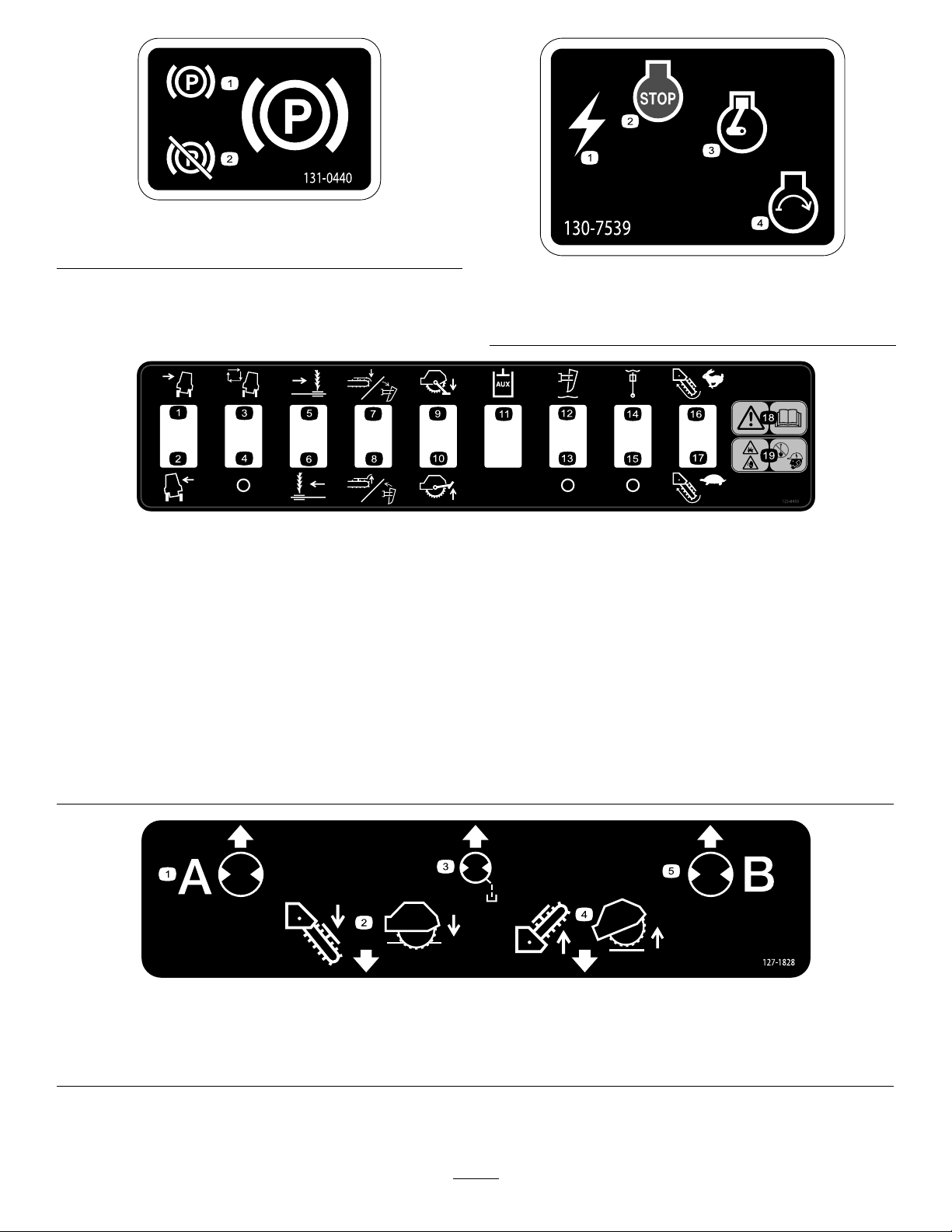
1.Parkingbrake—engage2.Parkingbrake—disengage
131-0440
130-7539
1.Electricalpower3.Engine—run
2.Engine—stop4.Engine—start
125-8495
1.Tiltthemachineright
2.Tiltthemachineleft7.Lowerthecrumber/rotate
3.Autoframelevelingon
(optionalkit)
4.Autoframelevelingoff
(optionalkit)
5.Sideshift—right(optional
attachment)
6.Sideshift—left(optional
attachment)
theplowforward(optional
attachment)
8.Raisethecrumber/rotate
theplowbackward(optional
attachment)
9.Rocksawstabilizer—lower
(optionalaccessory)
10.Rocksawstabilizer—raise
(optionalaccessory)
11.Auxiliaryhydraulic(optional
12.Vibratoryplowdepth—oat
13.Vibratoryplowdepth—oat
14.Vibratoryplowswing—oat
15.Vibratoryplowswing—oat
127-1828
kit)
on(optionalaccessory)
off(optionalaccessory)
on(optionalaccessory)
off(optionalaccessory)
16.Trencher—fastrotation
(optionalaccessory)
17.Trencher—slowrotation
(optionalaccessory)
18.Warning—readthe
Operator'sManual.
19.Explosionhazard;electric
shockhazard—donotdig
beforecontactinglocal
utilityservices.
1.Hydraulicpressure4.Raisetheattachment.
2.Lowertheattachment.5.Hydraulicreturn
3.Casedrain
12
Page 13
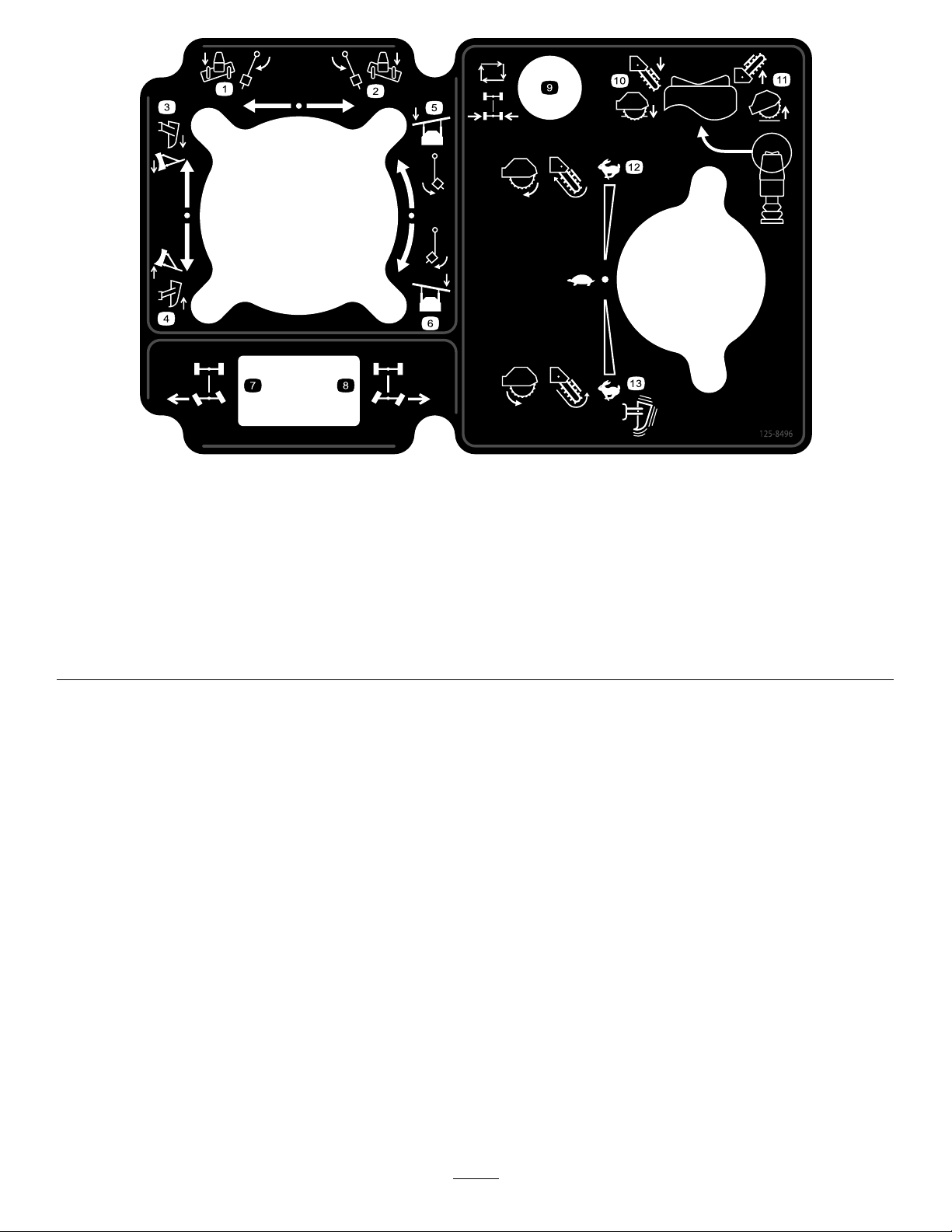
125-8496
1.Backllblade/vibratoryplow—tilt/swingleft
2.Backllblade/vibratoryplow—tilt/swingright9.Rearwheelsteering—autocenter(optionalkit)
3.Backllblade/vibratoryplow—lower
4.Backllblade/vibratoryplow—raise
5.Backllblade/vibratoryplowhead—angleleft12.Rearattachment—forwardspeed
6.Backllblade/vibratoryplowhead—angleright
7.Rearwheelsteering—turnthewheelsleft;machinewillturn
right
8.Rearwheelsteering—turnthewheelsright;machinewillturn
left
10.Lowertheattachments
11.Raisetheattachments
13.Rearattachment—reversespeed
13
Page 14
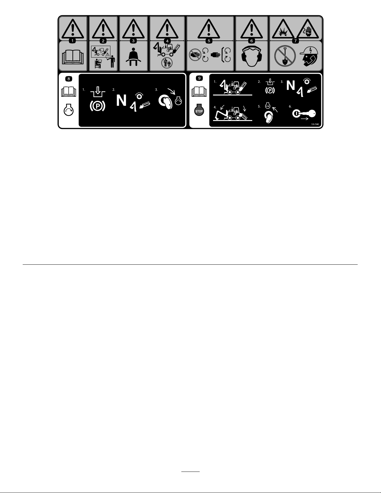
130-7540
1.Warning—readtheOperator'sManual.4.Warning—keepbystandersawayfrom
2.Warning—donotoperatethemachine
unlessyouhavereceivedinstruction.
3.Warning—wearaseatbelt.6.Warning—wearhearingprotection.
themachine.
5.Warning—keepawayfrommoving
parts;keepallguardsandshieldsin
place.
7.Explosionhazard;electricshock
hazard—beforediggingcallthelocal
utilitiesservice.
8.ReadtheOperator'sManualfor
informationonstartingtheengine—1)
Engagetheparkingbrake;2)Setthe
tractiondriveandallattachmentsto
neutral;3)Turnthekeytotheengine
startposition.
9.ReadtheOperator'sManualfor
informationonstoppingtheengine—1)
Parkthemachineonalevelsurface;
2)Engagetheparkingbrake;3)Set
thetractiondriveandallattachments
toneutral;4)Lowerallattachments;
5)Turnthekeytotheenginestop
position;6)Removethekeyfromthe
ignition.
14
Page 15
ProductOverview
Controls
Becomefamiliarwithallthecontrols(Figure9throughFigure
16)beforeyoustarttheengineandoperatethemachine.
CommandCenter
HomeScreenControls
Usethebuttonsonthecommandcentertocontrolthe
operationofmachinefunctions,andtonavigatetothe
machinesetupanddiagnosticscreens(Figure9).
Figure7
1.Nosepanel5.Fuelreservoir
2.Leftsidepanel
3.Grabhandles7.Steps
4.ROPSenclosure
6.Fuelcap
Figure8
1.Grabhandles4.Steps
2.Rightsidepanel
3.Nosepanel6.Hydraulic-tankcap
5.Hydraulic-uidsightgauge
Homescreenshown
1.Button1(lightOn/Off
button—usedwiththelight
kitoption)
2.Button2(increasethe
setpointfortheload
control—usedwiththe
load-controlkit)
3.Button3(decreasethe
setpointfortheload
control—usedwiththe
load-controlkit)
4.Button4(loadcontrol
On/Off—usedwiththe
load-controloption)
5.Button5(control
select—usetodetermine
whichattachmentthe
backll-blade/vibratory-plow
joystickoperates)
6.Button6
(advanced-steering
mode—usedwiththe
advanced-steeringkit)
7.Button7(increasethe
enginespeed)
Figure9
8.Button8(decreasethe
enginespeed)
9.Escape(usedtoreturnto
thehomescreen)
10.Previousscreen(usedto
movetoapreviousscreen
functionwithinascreen
mode)
11.OK(usedtomakea
selection)
12.Nextscreen(usedtomove
tothenextscreenfunction
withinascreenmode)
13.Downscreen(usedto
movedowntotheprevious
screenmodeandenter
diagnosticandcalibration
screens)
14.Upscreen(usedtomove
upthenextscreenmode)
15
Page 16
ThrottleButton
•Throttle-upButton—Pressthethrottle-upbutton
(button7),locatedatthebottom-rightcornerofthe
commandcenter,toincreasetheenginespeed(Figure9).
Note:Pressthebuttonrepeatedlytoincreasetheengine
speeduptothemaximumenginespeed(2,450rpm).
•Throttle-downButton—Pressthethrottle-downbutton
(button8),locatedatthebottom-rightcornerofthe
commandcenter,tolowertheenginespeed(Figure9).
Note:Pressthebuttonrepeatedlytodecreasetheengine
speeddowntotheengine-idlespeed(950rpm).
MachineControls
Differential-LockSwitch
Usethedifferential-lockswitchtocontrolthetransmissionof
powertoall4wheels(Figure10).
•Tolockthefrontandreardifferentials—pushtheswitch
up.
•Tounlockthefrontandreaddifferentials—stopthe
machine,pushtheswitchdown,andmovethemachine
backwardforashortdistance.
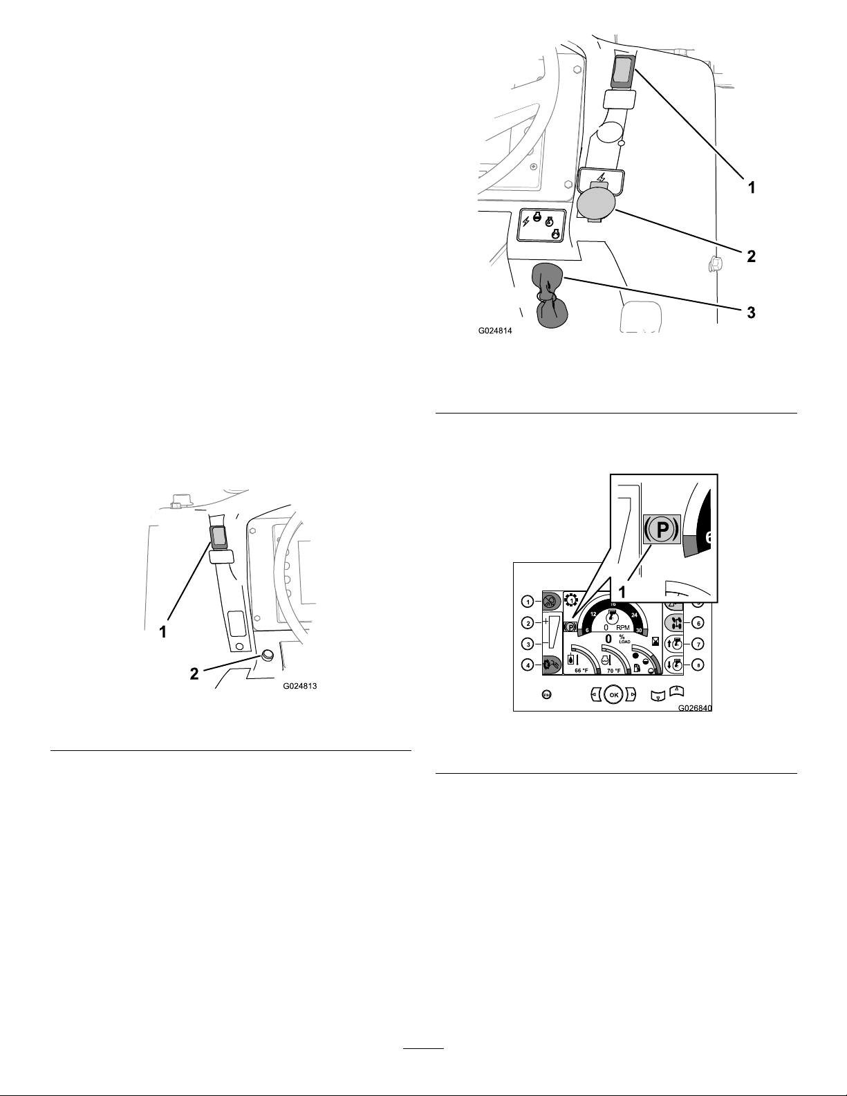
Figure11
1.Parking-brakeswitch3.Keyswitch
2.Powerport
Note:Theredparkingbrakeindicatorwillappearinthe
commandcenterdisplay(Figure12).
Figure10
1.Differential-lockswitch2.Hornbutton(optional)
Parking-BrakeSwitch
•Settheparkingbrakebypushingdowntheparking-brake
switch(Figure11).
Figure12
1.Parkingbrakeindicator(commandcenterdisplay)
•Releasetheparkingbrakebypushinguptheparking-brake
switch.
Note:Whentheparkingbrakeisreleasedandthe
machineismovedforwardorbackward,theHomescreen
willstopdisplayingtheparkingbrakeindicator.
•Ifyoustoptheenginewithoutsettingtheparkingbrake,
themachinewillsettheparkingbrakeandtheyellow
parkingbrakeindicatorwillappearinthecommand
centerdisplay(Figure12).
16
Page 17
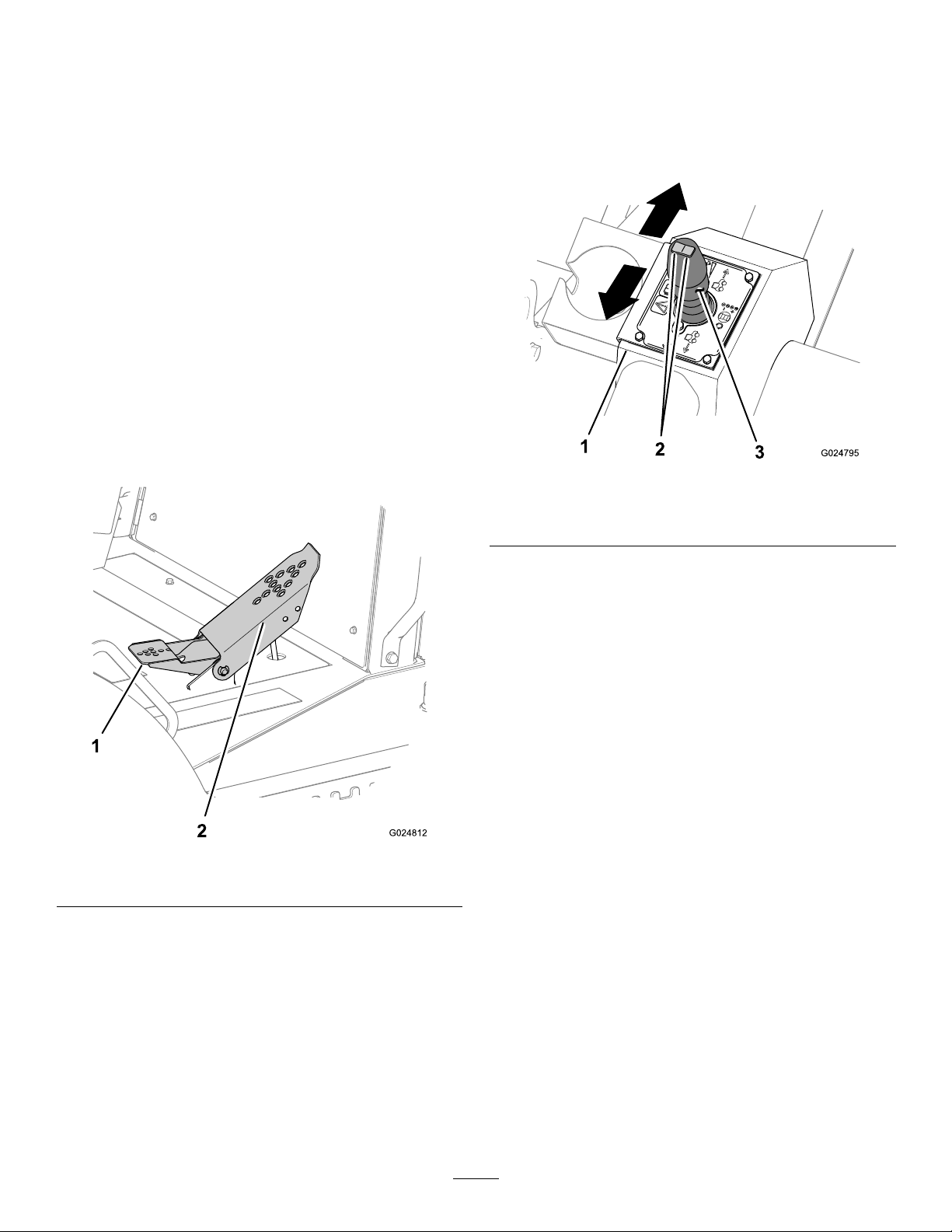
KeySwitch
3
Usethekeyswitchtopowertheelectricalaccessories,startthe
machine,andstopthemachine(Figure11).The4key-switch
positionsareasfollows:
•Accessory—Rotatethekeyswitchtothispositionto
energizethelampswitchcircuits.
•Stop—Rotatethekeyswitchtothispositiontostopthe
engineandde-energizetheelectricalsystem.
Note:Alwaysremovethekeybeforeleavingthe
machine.
•Run—Thispositionallowstheenginetorunandwill
energizeallelectricalsystems.
•Start—Rotatethekeyswitchtothispositiontostartthe
engine.
Note:Whenyoureleasethekey,itwillautomaticallygo
totheRunposition.
FootPedal
Thefootpedalcontrolsthedirectionandspeedoftravelof
themachine(Figure13).
•Movetheutility-tractionjoystickforwardtomovethe
machineforward(Figure14).
•Movethetractionjoystickrearwardtomovethemachine
inreverse(Figure14).
•Movethetractionjoysticktothecenter(Neutral)position
tostopthemachine(Figure14).
Figure14
Figure13
1.Heelpedal(reverse)2.Toepedal(forward)
Traction-ControlCluster
Thetraction-controlclusterislocatedattheoperatorseat,
adjacenttotheleftarmrest.
Utility-TractionJoystick
1.Traction-controlcluster3.Utility-tractionjoystick
2.Gear-selectorswitch
Note:Theenginespeediscontrolledwiththethrottle
buttonsonthehomescreenofthecommand-centerpanel;
refertoThrottleButton(page16).
Gear-SelectorSwitch
Thegear-selectorswitchislocatedontopoftheutility-traction
joystick(Figure14),andisusedtoselectthetransmissiongear.
Thecurrentgearisdisplayedonthehomescreenofthe
commandcenter,aboveandtotheleftofthetachometer
display.
Attachment-ControlCluster
Theattachment-controlclusterislocatedattheoperatorseat
andisadjacenttotherightarmrest.
Backll-Blade/Vibratory-PlowJoystick
Note:Thebackllbladeandthevibratoryplowareoptional
attachments.
Note:Thefunctionofthebackllblade/vibratoryplow
joystickdependsontheattachmentselectedinthecommand
center.
Whentrenching,plowing,orboring,usetheutility-traction
joysticktochangethedirectionandspeedofthemachine
(Figure14).Thefurtheryoumovethejoystickineither
direction,thefasterthemachinewillmoveintheselected
direction.
Thebackll-blade/vibratory-plowjoystickoperateseither
thebackllbladeorthevibratoryplow,whicheverisselected
anddisplayedonthecommandcenter.Movethejoystick
controlstochangethebackllbladeorthevibratoryplow
positionasfollows:
17
Page 18
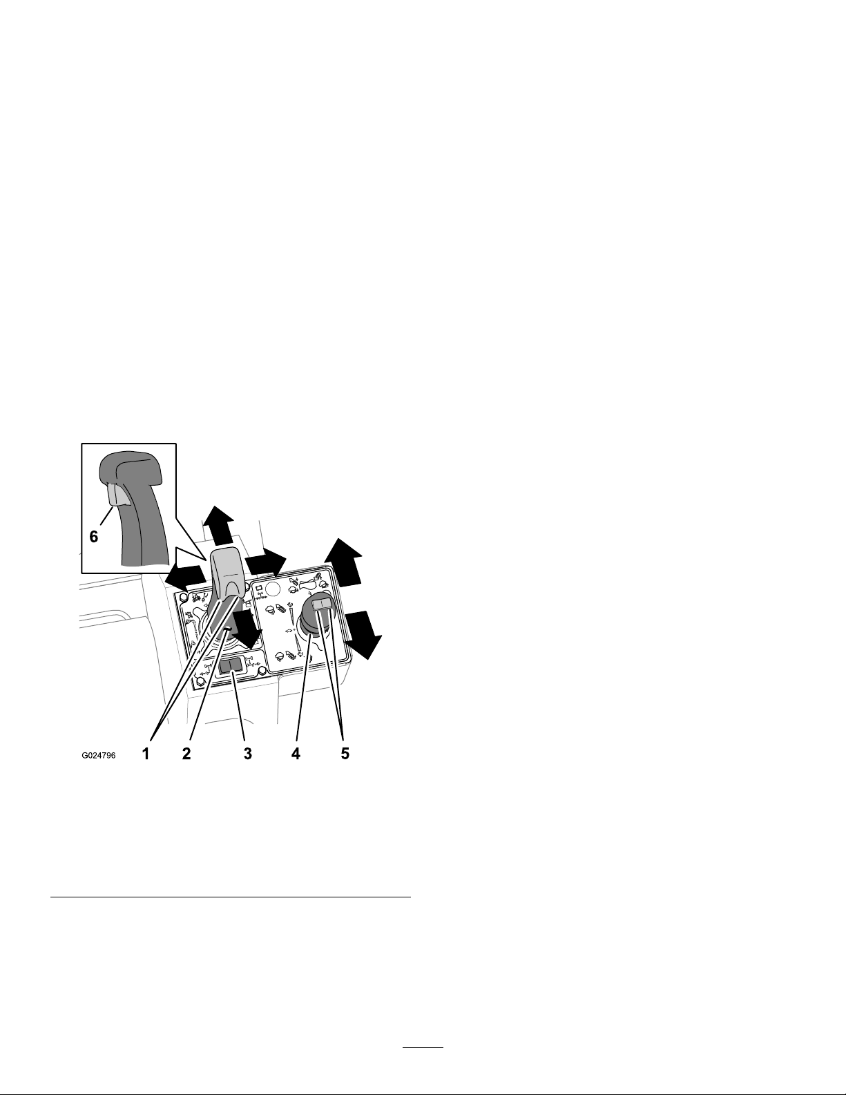
•Pushthejoystickforwardtolowerthebackllbladeor
vibratoryploworpullthejoystickrearwardtoraisethe
backllbladeorvibratoryplow(Figure15).
Note:Thefunctionofthejoystickdependsonthe
attachmentselectedinthecommandcenter.
Rear-Wheel-SteeringSwitch
Theswitchfortherear-wheelsteeringisusedtocontrolthe
steeringdirection(leftorright)oftherearwheels.Theswitch
fortherear-wheelsteeringislocatedbehindthebackll
blade/vibratoryplowjoystick.
•Movethejoysticktothelefttotiltthebackllbladetothe
left,ormovethejoysticktotherighttotiltthebackll
bladetotheright(Figure15).
•Swingthebackllbladeorsteerthevibratoryplowleftor
rightasfollows:
–Twistthethumbcontrollefttoswingthebackll
bladeleft,ortwistthethumbcontrolrighttoswing
thebackllbladeright(Figure15).
–Twistthethumbcontrollefttosteerthevibratory
plowleft,ortwistthethumbcontrolrighttosteerthe
vibratoryplowright(Figure15).
Note:Thefunctionofthethumbcontroldepends
ontheattachmentselectedinthecommandcenter.
•Pullthetriggeronthejoysticktooatthebackllblade
upanddown(Figure15).
Vibratory-Plow/Trencher-MotorJoystick
Note:Thevibratoryplowandthetrencherareoptional
attachments.
VibratoryPlow
Note:Thefunctionofthevibratoryplow/trenchermotor
joystickdependsontheattachmentselectedinthecommand
center.
•Movethejoystickrearwardtostartthevibrationofthe
plowblade(Figure15).
•Movethejoystickfurtherrearwardtoincreasethe
vibration(Figure15).
•MovethejoysticktowardtheNeutralpositiontodecrease
andstopthevibration(Figure15).
Trencher
•Movethejoystickforwardtostartthediggingchaininthe
forwarddirection(Figure15).
•Movethejoystickfurtherforwardtoincreasethechain
speed(Figure15).
1.Thumbcontrol
2.Backllblade/vibratory
plowjoystick
3.Rear-wheelsteering
switch
•MovethejoysticktotheNeutralpositiontostopthe
trencherchain(Figure15).
Figure15
4.Vibratoryplow/trencher
motorjoystick
5.Attachmentelevation
switch
6.Backll-blade-oattrigger
18
Page 19
Attachment-ElevationSwitch
Theattachment-elevationswitchraisesandlowersan
attachmentmountedattherearofthemachine.
•Presstheswitchonthelefttolowertheattachmentboom
(Figure15).
•Presstheswitchontherighttoraisetheattachment
boom(Figure15).
Note:Theneutral-indicatorlightturnsonwhenyou
turnthekeyswitchtotheOnpositionandboththe
utility-traction-controlandattachment-controlleversarein
theNeutralposition.
Note:Iftheoperatordoesnotremainseatedwhenthe
utility-tractionleverisnotintheNeutralposition,theengine
willstopin1second.Donotlayaheavyobjectontheseator
tamperwiththeseat-interlocksysteminanyway.
Auxiliary-ControlPanel
Theauxiliary-controlpanelincludestherockerswitchthat
controlsthemachinetiltactuator(Figure16).Thepanelalso
haslocationsforrockerswitchesthatareinstalledwiththe
optionalattachmentsorkitsforthemachine.
Figure16
1.Machinetilt—left/right
2.AutotiltOn/Off(reserved
foranoptionalkit)
3.Sideshiftleft/right
(reservedforanoptional
attachment)
4.Lower/raisethe
crumber/rotatetheplow
forward(reservedforan
optionalattachment)
5.Lower/raisetherocksaw
stabilizers(reservedforan
optionalattachment)
6.Auxiliaryhydraulic
(reservedforanoptional
attachment)
7.Vibratoryplowboomoat
On/Off(reservedforan
optionalattachment)
8.Vibratoryplowswingoat
On/Off(reservedforan
optionalattachment)
9.TrencherspeedFast/Slow
(reservedforanoptional
attachment)
Seat-HeightandSeat-SlideButtons
Figure17
1.Seat-slidebuttons5.Seat-frameslidebar
2.Seat-heightbuttons
3.Seat-slidelever
4.Seat-rotationlever8.Lumbarknob(locatedon
6.Weightcompensator
7.Armrest-heightcontrol
theseatback)
•Seat-heightbuttons–usethemtoadjusttheseatpadup
ordown(Figure17).
•Seat-slidebuttons—usethemtoslidetheseatpad
forwardorrearward(Figure17).
OperatorSeatandSeatBelt
Seat-InterlockSystem
WARNING
Theseat-interlocksystemprotectstheoperator
frominjury.
Donotdisabletheseat-interlocksystem.
Theseat-interlocksystemrequirestheoperatortositinthe
operatorseatwhileoperatingthismachine.
Seat-Frame-SlideLeverandSeat-Base-SlideLever
•Seat-frame-slidelever—Usethislevertoadjustthe
entireseatandframeforwardorrearward(Figure17).
•Seat-base-slidelever—Usethislevertomovetheseat
baseforwardorrearwardontheseatframe(Figure17).
19
Page 20
Seat-RotationLeverandSeat-WeightCompensator
•Seat-rotationlever—Usethislevertounlocktheseat
sothatyoucanrotatetheseattothedesiredposition.
Theseatwillrotate360°andlockintopositionat10°
increments(Figure17).
Note:RotatetheseattotheFrontpositionbefore
drivingthemachine.
•Seat-weightcompensator—Rotatethisleverforthe
weightcompensatortoadjusttheseatsupporttensionfor
theweightoftheoperator(Figure17).
–Rotatetheleverfortheweightcompensatorclockwise
toincreasethesupporttensionoftheseat.
–Rotatetheleverfortheweightcompensator
counterclockwisetoreducethesupporttensionof
theseat.
Figure18
Armrest-HeightControl
Rotatethearmrest-heightcontroltoraiseorlowerthe
armrest(Figure17).
Seat-LumbarKnob
Rotatetheseat-lumbarknob,foundbehindtheseat,toadjust
thebacklumbarsupportforbestcomfort(Figure17).
SeatBelt
WARNING
Operatingthemachinewithouttherollover
protectionsystem(ROPS)securelyinplacecan
resultinseriousinjuryordeathifthemachinerolls
over.
•Ensurethattherollbarissecurelyinplace.
•AlwayswearaseatbeltwiththeROPSinplace.
•Ensurethattheoperatorseatisproperlysecured
tothemachine.
Note:Regulationsinsomelocalitiesrequirethatseatbeltson
constructionmachinesbe76mm(3inch)wide.Checkwith
localauthoritiesregardingtherequirementsforseatbelts.
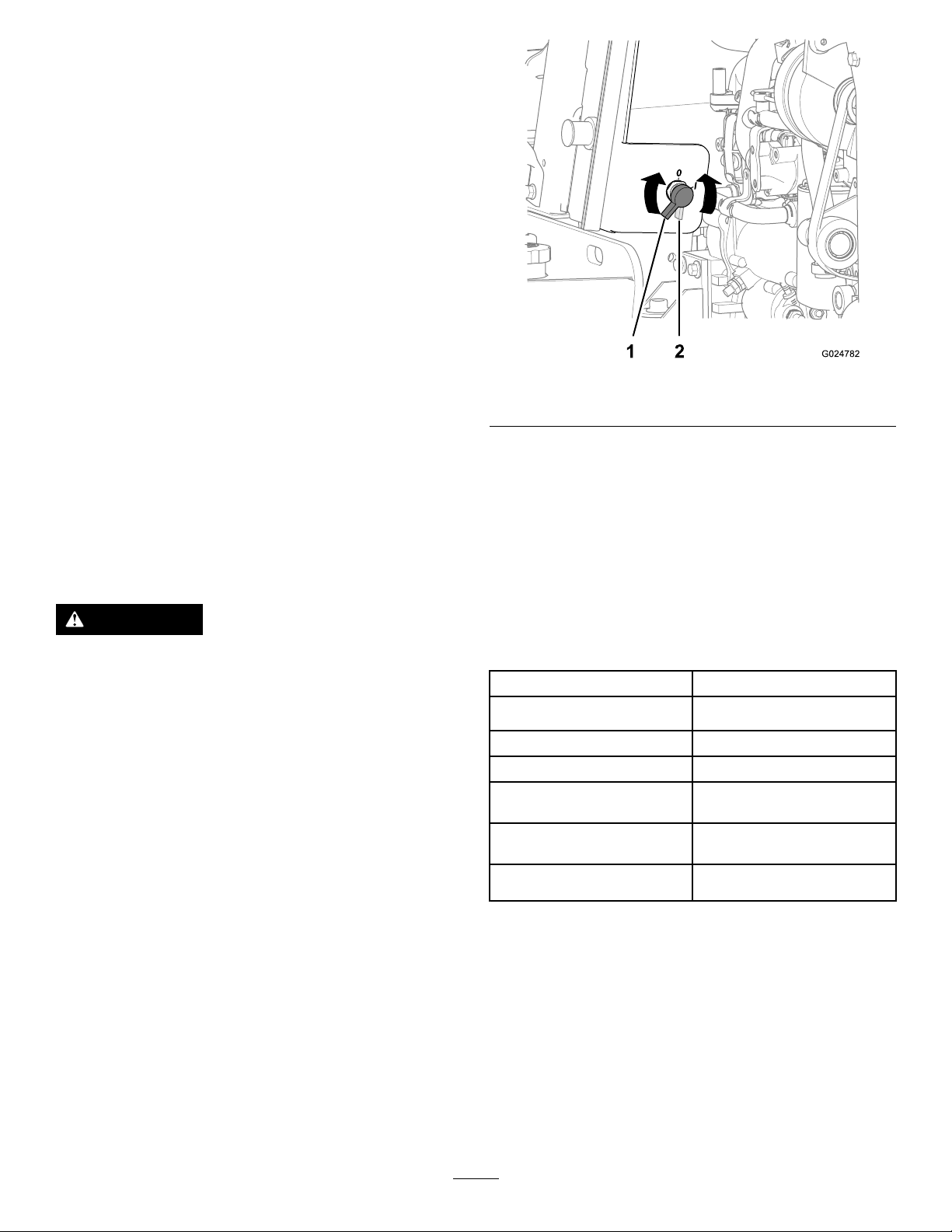
1.BatteryOnposition2.BatteryOffposition
•RotatethebatterydisconnectclockwisetotheOn
position.
•Rotatethebatterydisconnectcounterclockwisetothe
Offposition.
Specications
Note:Specicationsanddesignaresubjecttochange
withoutnotice.
MachineDimensionsandWeightData
Wheelbase
Overallheight(tothetopof
theROPS)
Overallwidth(atthetires)218cm(85.8inches)
Minimumgroundclearance
Turningradius(2-wheel
steering)
Turningradius(4-wheel
steering)
Weight(withoutattachments)4,343kg(9,575lb)
195cm(76.8inches)
281cm(110inches)
28.5cm(11.2inches)
115cm(291inches)
391cm(154inches)
•Tofastentheseatbelt,insertthetabendintotheleft
buckle.
Note:Ensurethatthetabendandthebuckleare
securelyfastened.
•Toreleasetheseatbelt,pushthebuttononthebuckle.
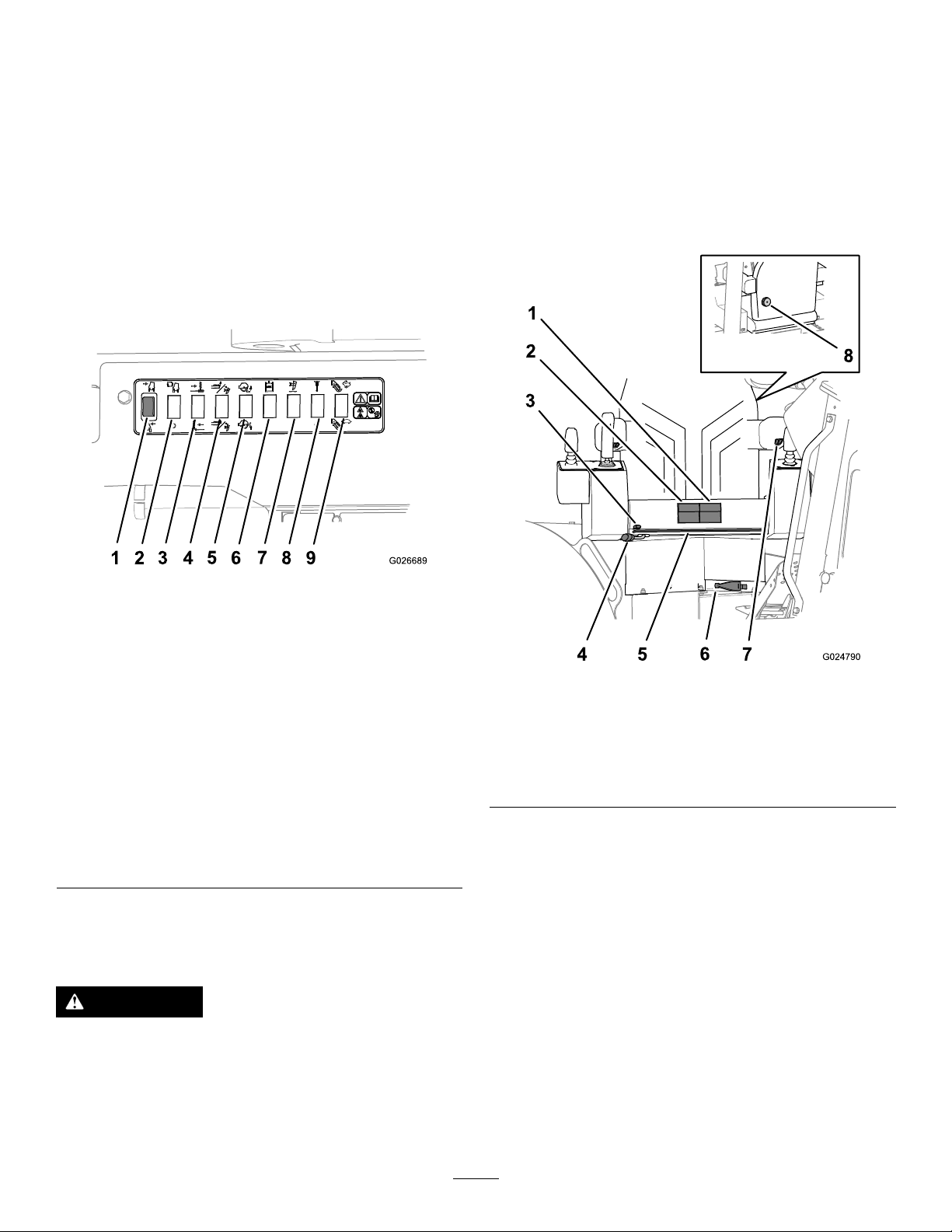
Battery-DisconnectSwitch
Thebattery-disconnectswitchislocatedbehindtheright
enginecowl(Figure18);useittoelectricallydisconnectthe
batteryfromthemachine.
Attachments/Accessories
AselectionofToroapprovedattachmentsandaccessoriesis
availableforusewiththemachinetoenhanceandexpand
itscapabilities.ContactyourAuthorizedServiceDealeror
Distributororgotowww .Toro.comforalistofallapproved
attachmentsandaccessories.
20
Page 21
Operation
G009027
1
2
•Gatherallrelevantinformationavailableaboutthejob
sitebeforeyoubeginworking.
Note:Determinetheleftandrightsidesofthemachine
fromthenormaloperatingposition.
ThinkSafetyFirst
Carefullyreadallsafetyinstructionsandsymbolsinthe
safetysection.Knowingthisinformationcouldhelpyouor
bystandersavoidinjury.
DANGER
Operatingonwetgrassorasteepslopescancause
slidingandlossofcontrol.
Wheelsdroppingoveranedgecancausearollover,
whichmayresultinseriousinjury,drowning,or
death.
Alwaysusetheseatbelt.
Readandfollowtherolloverprotectioninstructions
andwarnings.
Toavoidlossofcontrolandpossibilityofrollover:
•Donotoperatethemachineneardrop-offsor
nearwater.
•Reviewallblueprintsandotherplans,andidentifyall
existingorproposedstructures,characteristicsofthe
landscape,andotherproposedjobsintheareascheduled
atthesametimeasyourjob.
Notethefollowingitemsatthejobsite:
–Changesinelevationintheproposedworkarea
–Theconditionandtypeofsoilintheproposedwork
area
–Locationsofstructures,water,railroadtracks,and
otherobstructionsthatyouwillneedtoworknear
oraround
–Utilitymarkers,meters,andpoles
–Iftheworksiteisnearoronaroadwaywithtrafc,
callthelocalauthoritiesregardingpropersafety
proceduresandregulations.
–Accesstothesite
•CallyourlocalOne-Callservice(811intheUS)orthe
One-Callreferralnumber(888-258-0808intheUSand
Canada)andasktheparticipatingutilitycompaniesto
locateandmarktheirundergroundutilitylines.Alsocall
utilityprovidersthatarenotpartoftheOne-Callsystem.
•Reduceyourgroundspeedanduseextreme
cautiononslopes.
•Avoidsuddenturnsorrapidchangesinspeed.
CAUTION
Thismachineproducessoundlevelsthatcancause
hearinglossthroughextendedperiodsofexposure.
Wearhearingprotectionwhenoperatingthis
machine.
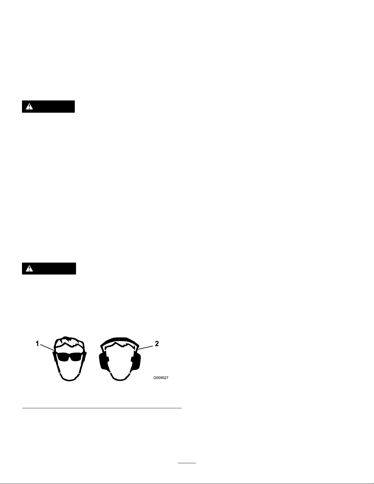
Theuseofprotectiveequipmentforeyes,ears,hands,feet,
andheadisrecommended.
Figure19
1.Wearsafetyglasses.
2.Wearhearingprotection.
PreparingforWork
Beforeoperatingthemachineonthejobsite,reviewthe
followingitems:
AddingFueltotheEngine
Fueltankcapacity:182L(48USgal)
Fueltype:ultra-lowsulfurdiesel(ULSD)
Note:Usingotherfuelscancausealossofenginepower
andhighfuelconsumption.
Important:Donotusekeroseneorgasolineinsteadof
dieselfuel;otherwise,youwilldamagetheengine.
UseonlydieselfuelforthemachinethatmeetsSpecication
D975oftheAmericanSocietyforTestingandMaterials
International.Seeyourdieselfueldistributor.
Useonlyclean,freshdieselfuelorbiodieselfuelswithlow
(<500ppm)orultralow(<15ppm)sulfurcontent.The
minimumcetaneratingshouldbe40.Purchaseonlyenough
fuelthatyouexpecttousewithin30daystoensurethatit
staysfresh.
Usesummer-gradedieselfuel(No.2-D)attemperatures
above20°F(-7°C)andwinter-gradedieselfuel(No.1-Dor
No.1-D/2-Dblend)below20°F(-7°C).Usingwinter-grade
fuelatlowertemperaturesprovidesalowerashpointand
coldowcharacteristics,whichaidinstartingtheengineand
helppreventcloggingthefuellter.
Usingsummer-gradefuelabove20°F(-7°C)contributes
towardalongerfuelpumplifeandincreasedpowercompared
tousingwinter-gradefuel.
21
Page 22
WARNING
Fuelisharmfulorfatalifswallowed.Long-term
exposuretofuelvaporscancauseseriousinjury
andillness.
•Avoidprolongedbreathingofvapors.
•Keepyourfaceawayfromthenozzleandthe
fueltankopening.
•Keepfuelawayfromyoureyesandskin.
DANGER
Incertainconditions,fuelisextremelyammable
andhighlyexplosive.Areorexplosionfromfuel
canburnyouandothersandcandamageproperty.
•Fillthefueltankoutdoorsinanopenareawhen
theengineiscold.Wipeupanyfuelthatspills.
•Neverllthefueltankinsideanenclosedarea.
•Neversmokewhenhandlingfuel,andstayaway
fromanopenameorwherefuelfumesmaybe
ignitedbyaspark.
•Storefuelinanapprovedcontainer,andkeep
itoutofthereachofchildren.Neverbuymore
thana30-daysupplyoffuel.
•Donotoperatethemachinewithouttheentire
exhaustsysteminplaceandinproperworking
condition.
portionshouldbeloworultra-lowsulfur.Observethe
followingprecautions:
•Thebiodieselportionofthefuelmustmeetspecication
ASTMD6751orEN14214.
•TheblendedfuelcompositionshouldmeetASTMD975
orEN590.
•Biodieselblendsmaydamagepaintedsurfaces.
•UseB5withabiodieselcontentof5%orlessincold
weather.
•Checkseals,hoses,andgasketsthatcomeincontactwith
thefuel,astheymaydegradeovertime.
•Thefuelltermaybecomepluggedforatimeafter
convertingtoabiodieselfuelblend.
•Contactyourdistributorformoreinformationabout
biodieselfuel.
StoringFuel
Ifyoustorefuelinastoragetank,itcanaccumulateforeign
materialorwater.Keepthefuelstoragetankoutside,and
keepthefuelascoolaspossible.Removewaterfromthefuel
inthestoragecontaineratregularintervals.
FillingtheFuelTank
Note:Fillthefueltankofthemachineattheendofeachday
topreventcondensationinthefueltank.
1.Cleanaroundthefuel-tankcap(Figure20),andremove
thecapfromthetank.
Incertainconditions,fuelingcanreleasestaticelectricityand
causeaspark,whichcanignitethefuelvapors.Areor
explosionfromfuelcanburnyouandothersandcandamage
property.
•Alwaysplacefuelcontainersontheground,awayfrom
yourvehiclebeforelling.
•Donotllfuelcontainersinsideavehicleoronatruck
ortrailerbed,becauseinteriorcarpetsorplastictruck
bedlinersmayinsulatethecontainerandslowtheloss
ofanystaticcharge.
•Whenpractical,removetheequipmentfromthetruck
ortrailer,andrefueltheequipmentwithitswheelson
theground.
•Ifrefuellingtheequipmentwithitswheelsontheground
isnotpossible,thenrefuelsuchequipmentonatruckor
trailerfromaportablecontainerratherthanfromafuel
dispensernozzle.
•Ifyoumustuseafueldispensernozzle,keepthenozzlein
contactwiththerimofthefueltankorcontaineropening
atalltimesuntilfuelingiscomplete.
UsingBiodieselFuel
Thismachinecanalsouseabiodieselblendedfuelofup
toB20(20%biodiesel,80%petrodiesel).Thepetrodiesel
1.Fillerneck
Figure20
2.Fuel-tankcap(off)
22
Page 23
Note:Removethecapslowlytoreducetheair
pressurebuildup.
2.Fillthefueltanktothebottomofthenecktoallow
spaceforthefueltoexpand.
Note:Thefueltankcapacityis182L(48USgal).
3.Installthefuel-tankcapandtightenitsecurelybyhand.
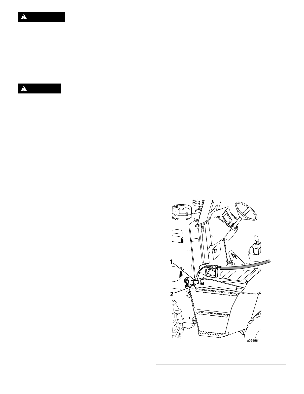
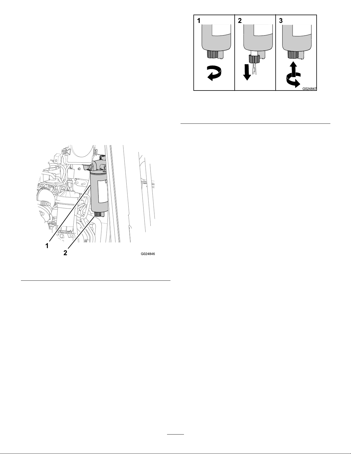
DrainingWaterfromtheFuel-Water
Separator
ServiceInterval:Beforeeachuseordaily
1.Removetheleftsidepanel;refertoRemovingtheSide
Panels(page44).
Figure22
1.Openthedrainvalve.3.Closethedrainvalve.
2.Drainthewater.
2.Placeadraincontainerbelowthedrainvalveonthe
fuel-waterseparator(Figure21).
Figure21
1.Fuel-waterseparator2.Drainvalve
3.Rotatethedrainvalvecounterclockwiseapproximately
3-1/2turnsuntilthevalvedropsdownfromthe
fuel-waterseparator(Figure22).
4.Drainthewaterandsedimentfromtheseparatoruntil
clearfuelisvisible(Figure22).
5.Liftupthevalveandturnitclockwiseuntilitishand
tight(Figure22).
Note:Donotovertightenthedrainvalveofthe
fuel-waterseparator;overtighteningthevalvecan
damagethethreadsofthevalve.
6.Installtheleftsidepanel;refertoInstallingtheSide
Panels(page45).
Note:Thevalveshouldextend25mm(1inch)from
theseparator.
23
Page 24
CheckingtheEngine-OilLevel
ServiceInterval:Beforeeachuseordaily
Note:Theengineisshippedwithoilinthecrankcase;
however,checktheoillevelbeforeandafteryourststart
theengine.
Oilspecication:APIclassicationofCJ-4orhigher
Useonlyhigh-qualitySAE15W -40heavy-dutyengineoilwith
anAPIclassicationofCJ-4orhigher.
WhileSAE15W-40oilwithanAPIclassicationofCJ-4or
higherisrecommendedformostclimates,refertoFigure23
foroilviscosityrecommendationsforextremeclimates.
Figure23
Figure24
1.Dipstick2.Dipsticktube
Note:Limiteduseoflow-viscosityoilssuchasSAE10W-30
withanAPIclassicationofCJ-4orhighercanbeusedfor
easierstartingandprovidingsufcientoilowatambient
temperaturesbelow-5°C(23°F).However,continuoususeof
low-viscosityoilcandecreaseenginelife.
ToroPremiumEngineOilisavailablefromanAuthorized
ToroServiceDealerineither15W -40or10W-30viscosity
withAPIclassicationCJ-4orhigher.SeethePartsCatalog
forpartnumbers.Also,refertotheengineoperator'smanual,
includedwiththemachine,forfurtherrecommendations.
Important:Iftheoillevelinthecrankcaseistoolow
ortoohighandyouruntheengine,youmaydamage
theengine.
Note:Thebesttimetochecktheengineoiliswhenthe
engineiscoolbeforeithasbeenstartedfortheday.Iftheoil
levelisatorbelowtheAddmarkonthedipstick,addoilto
theenginetobringtheoilleveluptotheFullmark.Donot
overll.IftheoillevelisbetweentheFullandAddmarkson
thedipstick,youdonotneedtoaddoil.
1.Ensurethatthemachineisonalevelsurface.
2.Lowerallattachments,settheparkingbrake,stopthe
engine,andremovethekey.
Note:Ifyouhaveruntheengine,allowatleast15
minutesfortheengineoiltosettleinthecrankcase.
Figure25
5.Insertthedipstickfullyintothedipsticktube,then
removethedipstick(Figure24).
6.Readtheoillevelonthedipstick(Figure25).
Note:Theoillevelonthedipstickshouldbebetween
theH(high)markandL(low)mark.
•Iftheoillevelistoolow ,slowlypourasmall
amountofthespeciedoilintotheoil-llerneck
(Figure64)andwait3minutes;refertostep1in
FillingtheEnginewithOil(page46).
Important:Donotoverlltheenginewithoil.
•Iftheoillevelistoohigh,draintheexcessoiluntil
youobtainthecorrectoillevelonthedipstick;
refertoDrainingtheEngineOil(page45).
7.Repeatsteps4through6untiltheoilleveliscorrect.
8.Installthedipstickandoil-llcapsecurely.
9.Installtheleft-sidepanel;refertoInstallingtheSide
Panels(page45).
3.Removetheleft-sidepanel;refertoRemovingtheSide
Panels(page44).
4.Removethedipstickandwipeitcleanwithaclean
cloth(Figure24).
24
Page 25

CheckingtheCoolantLevelin
2
1
g024979
CheckingtheHydraulic-Fluid
theReservoir
ServiceInterval:Beforeeachuseordaily
Iftheengineoverheatwarningisdisplayedonthecontrol
panel,checkthecoolantlevelinthereservoirandaddcoolant
ifitislow.Alsoinspecttheenginecompartmentaroundthe
radiatorandclearawayanyobstructionstoairow .
1.Parkthemachineonalevelsurface,stoptheengine,
andremovetheignitionkey.
2.Allowtheenginetocool.
3.Removetheleftsidepanel;refertoRemovingtheSide
Panels(page44).
4.Checkthecoolantlevelinthereservoir(Figure26).
Level
ServiceInterval:Beforeeachuseordaily
Hydraulicuidspecication:Mobiluid424
Note:Manybrandsofhydraulicuidarealmostcolorless,
makingitdifculttodetectleaks.Areddyeadditiveforthe
hydraulicsystemoilisavailablein20ml(0.68oz)bottles.
Onebottleissufcientfor15.1to22.7L(4.0to6.0US
gal)ofhydraulicuid;youcanorderthisadditivefroman
AuthorizedToroServiceDealer.
1.Parkthemachineonalevelsurface,andputallthe
attachmentsinthetransportposition.
2.Stoptheengine,settheparkingbrake,andremovethe
ignitionkey .
3.Checkthehydraulic-uidlevelinthesightglasslocated
atthesideofthehydraulicreservoir(Figure27).
Figure26
1.Reservoir
Note:Ensurethatthecoolantlevelisbetween1/4
and3/4ofthewayupinthesightglass(Figure26).
5.Addthespeciedcoolantuntilthecoolantlevelis
between1/4and3/4ofthewayupinthesightglass.
Note:Ensurethatthecoolantsolutionisthoroughly
mixedbeforellingthereservoir.
6.Installtheleftsidepanel;refertoInstallingtheSide
Panels(page45).
2.Coolantlevel(halfway
betweentheAddandFull
marks)
Figure27
1.Fillcap(off)3.Hydraulicuidlevelatthe
midpointofthesightglass
2.Hydraulicuid
Note:Thehydraulic-uidlevelshouldbebetweenthe
bottomandmidpointofthesightglass.
4.Ifthehydraulic-uidlevelisnotvisibleinthesight
glass,removethellcap(Figure27),addthespecied
hydraulicuiduntiltheuidlevelisatthemidpointof
thesightglass,andinstallthellcap.
25
Page 26

CheckingtheRestricted Air-CleanerIndicator
ServiceInterval:Beforeeachuseordaily
1.Starttheengine;refertoOperatingtheEngine(page
33).
2.Checktoseeiftherestrictedair-cleanerindicatoris
displayedinthehomescreenofthecommandcenter
(Figure28).
•Cleanmachinecomponentsthatyouuse.
•Removeanylooseitemsfromthemachine.
•Checkthemachineforbroken,damaged,loose,or
missingparts.Replace,tighten,oradjusttheseparts
beforeyouoperatethemachine.
•RepairorreplacealldamagedROPSandseatbeltparts.
OperatingtheCommand Center
SoftwareMessages
Thecommandcenterwilldisplayinformationaboutthe
controllerversion,displayversion,andinstalledoptional
attachmentsorkitsthatareoperatedthroughthecommand
center.Thisinformationisdisplayedonthesplashscreen
duringstartupofthemachine,asshowninAofFigure29
orwhenyouaccessthemainselectionscreen,asshowninB
ofFigure29.
Figure28
1.Restrictedair-cleaner
indicator
3.Replacetheair-cleanerelement(s)asfollows:
A.Replacetheprimaryair-cleanerelement;referto
ReplacingtheAir-cleanerElements(page48).
B.Repeatsteps1and2.
C.Iftherestrictedair-cleanerindicatorisstill
displayed,replacethesecondaryair-cleaner
element;refertoReplacingtheAir-cleaner
Elements(page48).
2.Commandcenter
InspectingtheMachine
ServiceInterval:Beforeeachuseordaily
Inspectthefollowingitemsonthemachineeachdaybefore
youstarttheengine:
•Checkforleaksunderthemachine,andrepairallleaks.
•Checkthetiresforwear,damage,andlowpressure.
•Checkthemachinefordebris,especiallyaroundthe
engine.
Figure29
1.Maincontrollerversion3.Installedoptional
attachmentsorkits
2.Displayversion
Note:Ensurethattheareaneartheengineiscleanso
thattheenginecoolsproperly.
•Cleanorreplaceanysafetyorinstructionaldecalthatyou
cannotread.
26
Page 27

UsingtheHomeScreen
Usethepreviousscreen,nextscreen,downscreen,orup
screenbuttonstodisplayeithertherpmhomescreen(Aof
Figure30),the%loadhomescreen(BofFigure30)orthe
mainselectionscreen(CofFigure30).
Figure31
1.Gearindicator6.Checkalternatororbattery
2.Parkingbrakeindicator7.Hourmeter
3.Tachometer
4.Machineorengineerror
5.Lowengine-oilpressure10.Fuellevel
ReadingtheOperatingIndicatorsintheCommand
Display
8.Hydraulic-uid
temperature
9.Coolanttemperature
Figure30
1.Previousscreenbutton3.Downscreenbutton
2.Nextscreenbutton4.Upscreenbutton
Understandthemeaningoftheiconsthatindicatethe
functionsandthestateofthemachine.
Displaythehomescreenofthecommandcentertond
informationaboutthetransmission,engine,hydraulicsystem,
andfuelquantity.
•Gearindicator—Thisindicatorshowswhichgearis
selectedforthetransmission(gears1through4)andis
displayedaboveandtotheleftoftachometer(Figure31).
•Tachometer—Thetachometerindicatestheengine
speedinrevolutionsperminute(rpm).Thetachometer
isdisplayedintheuppercenterofthecommand-center
display(Figure31).
Note:Eachnumberonthegaugeisequaltox100rpm.
Eachspaceonthegaugeisequalto600rpm.Therange
ofthetachometerdisplayis0to3000rpm.
•Hourmeter—Thehourmeterindicatesthenumber
ofhoursthattheenginehasrun.Itisdisplayedinthe
centerrightareaofthecommanddisplay,totherightof
thetachometer(Figure31).
•Hydraulic-uidtemperatureindicator—Thisindicator
showstheoperatingtemperatureofthehydraulicuid
andisdisplayedinthelowerleftareaofthecommand
display(Figure31).
Note:Iftheindicatormovesintotheredarea,reduce
theworkspeed.Ifthegaugeremainsintheredarea,stop
themachineandmovethedirectioncontrollevertothe
Neutralposition.Checktheoillevelandforobstructions
intheradiatorortheoilcooler.
•Coolanttemperatureindicator—Thisindicatorshows
thetemperatureofthecoolantintheengine-cooling
system.Itisdisplayedinthelowercenterareaofthe
instrumentcluster(Figure31).
27
Page 28
Note:Iftheindicatorgoesintotheredarea,reduce
theenginespeedtoidleforafewminutestoallowthe
enginetocool,thenstoptheengine.Checkthecoolant
level,fordebrisontheradiator,orforathermostatthat
doesnotoperatecorrectly.Alsocheckthedrivebelt,belt
tensioner,orwater-pumppulley.
•Fuel-levelindicator—Thisindicatorshowsthe
remainingleveloffuelthatisinthetank,anditis
displayedinthelowerrightareaofthecommanddisplay
(Figure31).
•Parking-brake-onindicator—Thisindicatoris
displayedwhiletheparkingbrakeisengaged(Figure31).
Theindicatordisappearswhenyoureleasetheparking
brake.
ChangingUnitsofMeasure
UsethisproceduretochangefromEnglishtometricunitsor
frommetrictoEnglishunits
1.Displaythehomescreenofthecommandcenter
(Figure32).
Figure33
1.Machineorengineerror
2.Lowengine-oilpressure
(ashes)
3.Highhydraulic-oil
temperature(ashes)
4.Checkalternatororbattery
5.Engineoverheated
(ashes)
6.Lowfuelquantity(ashes)
•Machineorengineerror—Thismessagedisplaysifthe
machineorengineexperiencesafault.Thecauseofthe
faultisgivenintheInstrumentPanelDiagnostics(Figure
33).
Figure32
1.Left+right+upbuttons
2.Presstheleft+right+upbuttons(Figure32).
Note:Theunitsofmeasureshouldchangefrom
EnglishtometricunitsorfrommetrictoEnglishunits.
Note:Ifthedisplaychangesfromthehomescreento
themainselectionscreen,presstheleft,right,up,or
downbuttontoreturntothehomescreen.
ReadingtheWarningMessagesintheCommand
Display
Note:Whentherearewarningmessagesinthecommand
display,takecorrectivemeasuresimmediately.Theremaybe
morethan1warningdisplayed.
Important:
Do not
runtheengineifthiswarning
messageappears.
•Lowengine-oilpressure—Thiswarningmessage
displaysiftheoilpressureoftheengineis90Kpa(13psi)
orlower(Figure31andFigure33).
Important:
Do not
runtheengineifthiswarning
messageappears.
•Highhydraulic-oiltemperature—Thismessageashes
iftheoilinthehydraulicsystemis102°C(215°F)or
higher(Figure33)
Important:
Do not
runtheengineifthiswarning
messageappears.
•Checkalternatororbattery—Thismessagedisplays
ifthealternatorandbatteryvoltageis12voltsorless
(Figure31andFigure33).
Note:Ifthismessageisappears,stoptheengine,repair
thechargingsystem,orreplacethebattery.
•Engineoverheated—Thismessageashesiftheengine
coolantis104°C(220°F)orhigher(Figure31andFigure
33).
Important:
Do not
runtheengineifthiswarning
messageappears.
•Lowfuelquantity—Thismessagedisplayswhenthefuel
quantityinthetankislessthan18.2L(5.8USgal).
•Wait-to-start-engineindicator—Thisindicatordisplays
whenthekeyswitchisintheOnpositionandtheintake
airheaterfortheengineisenergized(Figure34).
Note:Waituntiltheindicatornolongerappearsbefore
attemptingtostarttheengine(Figure34).
28
Page 29

Note:Ifthismessageisdisplayed,stoptheengineand
replacethehydraulic-returnlter.
•Hydraulic-chargelterrestriction(traction
motor)—Thismessageisdisplayedifthechargelterfor
thetractionmotorisrestricted(Figure35).
Note:Ifthismessageisdisplayed,stoptheengineand
replacethehydraulic-chargelterforthetractionmotor.
•Air-lterrestriction(engine)—Thismessageis
displayedwhentheairlterrequiresservice(Figure35).
Figure34
1.Wait-to-start-engineindicator
ReadingtheMachineorEngineErrorIndicatorsinthe
CommandDisplay
Note:Whenawarningindicatorisshowninthecommand
display,takecorrectivemeasuresimmediately.
Figure35
1.Hydraulic-chargelter
restriction(transmission)
2.Hydraulic-chargelter
restriction(accessories)
3.Hydraulic-returnlter
restriction
4.Hydraulic-chargelter
restriction(tractionmotor)
5.Air-lterrestriction
(engine)
6.Returnthejoystickto
neutralindicator
•ReturntoNeutralindicator—Thisindicatoris
displayedifyouattemptanoperationthatrequiresyouto
returnthejoystickorthetractionpedaltotheNeutral
position.Returnthejoystickorthetractionpedaltothe
Neutralpositionbeforecontinuingoperation(Figure35).
Note:Thismessagealsoappearsifyoustarttheengine
wheneithertheutilitydriveortheattachmentjoysticksat
theoperatorseatarenotintheNeutralposition.Move
thejoystickstotheNeutralpositiontoclearthewarning.
•Hydraulic-chargelterrestriction
(transmission)—Thismessageisdisplayedif
thehydraulic-chargelterforthetransmissionisrestricted
(Figure35).
Note:Ifthismessageisdisplayed,stoptheengineand
replacethehydraulic-chargelterforthetransmission.
•Hydraulic-chargelterrestriction
(accessories)—Thismessageisdisplayedifthe
chargelterforthehydrauliccircuitfortheaccessoriesis
restricted(Figure35).
Note:Ifthiswarningmessageisdisplayed,stopthe
engineandreplacethechargelterforthehydraulic
circuitfortheaccessories.
•Hydraulic-returnlterrestriction—Thismessageis
displayedifthehydraulic-returnlterisrestricted(Figure
35).
29
Page 30

AccessingtheMain-SelectionScreen
Toaccessthemain-selectionscreen,pressandreleasetheup
arrowandthedownarrowbuttons(Figure36)atthesame
time.Thisscreenallowstheusertochoosefromthefunction
screensshowninFigure36.
Figure36
1.Engineinformation5.Trencher(tractionunit)
2.Trencher(tractionunit)
setup
3.Screensetup7.Propel(groundspeed)
4.Trencher(tractionunitand
attachments)diagnostics
errors
6.Engineerrors
limits
Figure37
1.Returntothepreviousscreen
AccessingtheTrencherSetupFunctionScreen
Note:YouneedthePINtoaccessthisscreen;toobtainthe
PIN,contactanAuthorizedToroDistributor.
Usethetrenchersetupscreentoaccesscalibrationsettings
forthefollowingfunctions:
•Footpedalfortractioncontrol
•Advanced-steeringcontrol(optionalaccessory)
•Automatic-tiltchassis(optionalaccessory)
AccessingtheScreenSetupFunctionScreen
AccessingtheEngineInformationScreen
Toaccesstheengine-informationscreen,pressbutton
number1onthemain-selectionscreen;refertoAccessingthe
Main-SelectionScreen(page30).
Thisscreendisplaysmeasurementsforthefollowing
engine-operatingparameters:
•Enginespeedinrpm(Figure37)
•Engineloadpercentage(Figure37)
•Enginehours(Figure37)
•Oilpressureandboostpressure(Figure37)
•Enginecoolantandintaketemperature(Figure37)
•Voltage(Figure37)
•Amountoffuelused(Figure37)
Toaccessthescreensetupfunction,pressbuttonnumber
3onthemain-selectionscreen;refertoAccessingthe
Main-SelectionScreen(page30).
Thisscreenallowstheusertoincreaseordecreasethe
brightnessofthemonitorbypressingthefollowing:
•Button5—Increasethedisplaybrightness(Figure38)
•Button6—Decreasethedisplaybrightness(Figure38)
30
Page 31

Figure39
AccessingtheEngineErrorsInformationScreen
Figure38
1.Displaybrightness
indicator
2.Decreasebrightness4.Returntotheprevious
AccessingtheTrencherDiagnosticsFunctionScreen
3.Increasebrightness
screen
Usethetrencherdiagnosticscreentoviewstateandsignal
informationforthefollowingmachineandattachment
functions:
•Tractioncontrol
•Optionaltrencherattachment
•Optionalvibrationplowattachment
•Optionalbackhoeattachment;Optional/standard
backllbladeattachment
•Optionalautomatic-tiltchassis
•Optionaladvanced-steeringcontrol
AccessingtheTrencherErrorsInformationScreen
Usethetrencherdiagnosticscreen(Figure40)viewsuspect
partnumber—failuremodeidentier(SPN-FMI)codesfor
theengine;contactanAuthorizedServiceDealer.
Figure40
SettingthePropel-LimitFunctionScreen
Usethepropel-limitfunctiontorestricttheforward
andreversegroundspeedthatyoucancontrolwiththe
utility-tractionjoystick.
Usethetrencherdiagnosticscreen(Figure39)viewsuspect
partnumber—failuremodeidentier(SPN-FMI)codesfor
thetractionunit;contactanAuthorizedServiceDealer.
Note:Youcanrestrictthegroundspeedcontrolledbythe
utility-tractionjoystickbyapercent(15to100%)ofthe
groundspeedthatyoucansetwiththefootpedal.
1.Fromthemain-selectionscreen,pressbuttonnumber
7accessthesettingsforthepropellimitfunction;refer
toFigure36inAccessingtheMain-SelectionScreen
(page30).
31
Page 32
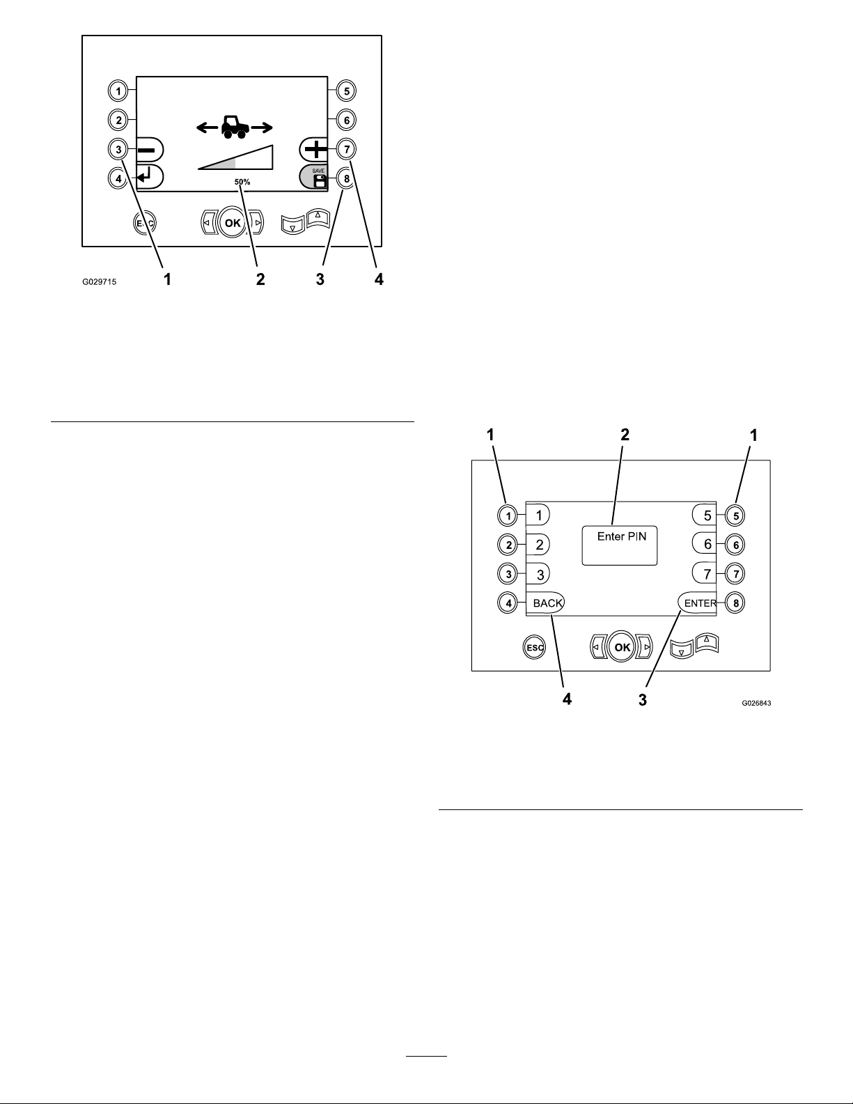
UsingthePINscreen
Note:ThisprocedurerequiresthatyouhavethePIN
number,whichyoucanobtainfromanAuthorizedService
Dealer.
Note:T oaccessthetrenchersetupfunctionforthemachine,
youmustentertheunique8-digitidenticationnumber
assignedintothePINscreen.Thetrenchersetupfunctions
protectedbythePINscreenincludethefollowing:
•Pedalcalibration
•Steeringsetup
•Auto-tiltsetup
Figure41
1.Decreasetherangeof
groundspeedsetwiththe
utility-tractionjoystick
2.Percentsetting(50%
shown)
3.Savesetting
4.Increasetherangeof
groundspeedsetwiththe
utility-tractionjoystick
2.Setthegroundspeedlimitfortheutility-traction
joystickasfollows:
•Pressbutton3(Figure41)tolowerthepercent
ofgroundspeedthatyoucansetwiththe
utility-tractionjoystick(downto15%oftheground
speedthatyoucansetwiththefootpedal.).
Note:Thisgivesyounercontroloverasmaller
rangeofgroundspeed.
•Pressbutton7(Figure41)toincreasethepercent
ofgroundspeedthatyoucansetwiththe
utility-tractionjoystick.
Note:Thisgivesyoucoursercontroloveralarger
rangeofgroundspeed(upto100%oftheground
speedthatyoucansetwiththefootpedal.
3.Pressbutton8tosaveyoursetting(Figure41).
Note:Thesaveiconmomentarilydisplaystheword
Saveandturnsgreen.
1.Pressbuttonnumber2[Trencher(tractionunit)setup]
onthemain-selectionscreen;refertoAccessingthe
Main-SelectionScreen(page30).
2.Enterthe8-digitPIN.
3.Pressbuttonnumber8[Enter].
Note:Numbers1,2,3,5,6,and7aretheonlynumbers
thatcanbeusedforthePIN.
Figure42
1.Buttonsforcorresponding
PINnumbers
2.PINentryappearshere4.Returntotheprevious
3.EnterPIN
screen
32
Page 33

OperatingtheEngine
BeforeStartingtheEngine
1.Checktheoillevel;refertoCheckingtheEngine-Oil
Level(page24).
2.Ensurethatthebattery-disconnectswitchisintheOn
position;refertoBattery-DisconnectSwitch(page20).
3.Adjusttheseatposition,fastentheseatbelt,andensure
thattheseatisfacingforward.
Note:Theseatinterlocksystempreventsyoufrom
operatingthemachineunlessyouaresittinginthe
operatorseat.Ifyoudonotremainseatedand
thecontrolleversarenotintheNeutralposition,
thesystemwillstopboththegrounddriveandthe
attachmentdrivein1second.Donotsetaweighted
objectontheseat,bypasstheseatinterlocksystem,
ortamperwiththesystem.
4.Settheparking-brakebuttontotheOnposition;refer
toParking-BrakeSwitch(page16).
5.EnsurethatallcontrolleversareintheNeutralor
theStopposition;refertoFootPedal(page17),
Utility-TractionJoystick(page17),andBackll-Blade/
Vibratory-PlowJoystick(page17)/Vibratory-Plow/
Trencher-MotorJoystick(page18).
Note:Ifthemachineisequippedwithabackhoe,
ensurethattheengineshutoffcontrolispulledup.
intakeairtowarmupbeforestarting.Whentheintake
airisatthepropertemperatureforstartingtheengine,
thewait-to-startindicatorinthedisplayturnsoff.
2.TurnthekeyswitchtotheStartposition.
Note:Iftheenginestartsandthenstops,donot
turnthekeyswitchtotheStartpositionagainuntilthe
startermotorhasstoppedturning.
Important:
itstopsturning.
formorethan30secondsatonetime.Allowthe
startermotortocoolfor30secondsbeforeyou
operateitagain.Whenyouengagethestarter
motor,youshouldseewhiteorblacksmoke
comingfromtheexhaustpipe;ifyoudonot,check
thefuelsupply.
3.Whentheenginestarts,checkthecommand-control
displaytoensurethattheindicatorreadingsarecorrect.
Ifanyoftheindicatorsappearonthedisplay,stopthe
engineandchecktheproblem.
4.Runattheengineat1100rpmuntilthecoolantis
warm;refertoSettingtheEngineSpeed(page33).
5.Cycleallthemachinecomponentsbeforeoperatingthe
machine,andcheckallthecontrolsandcomponentsto
ensurethattheyareworkingproperly.
Note:Iftheengineisnewornewlyrebuilt,referto
BreakinginaNeworRebuiltEngine(page34).
Do not
operatethestartermotoruntil
Do not
operatethestartermotor
StartingtheEngine
WARNING
Beforestartingtheengine,sitintheoperatorseat,
fastentheseatbelt,applytheparkingbrake,and
ensurethatthetransmissiondirectioncontroland
diggingcontrolleversareintheNeutralposition.
Warnallbystandersthatyouarestartingtheengine.
Important:Whenyoustarttheengine,thetransmission
isautomaticallysettorstgearandtheautocentering
fortherearsteering(optionaladvanced-steeringkit)is
inthemanualmode.
Note:Inextremehotorcoldweather,takethenecessary
precautions;refertoOperatingtheMachineinExtreme
Conditions(page34).
1.TurnthekeyswitchtotheOnpositionandcheckthat
allcontrolsareintheNeutralposition.
Note:Thelowengine-oilpressureindicatorandthe
checkalternatororbatterydisplayswhenthekeyswitch
isintheOnpositionandtheengineisnotrunning.
SettingtheEngineSpeed
Note:Donotruntheengineatfullthrottlebelowthepeak
torquerpm(refertotheenginedataplateforthepeaktorque
rpm)formorethat30seconds.
Note:Donotruntheengineatalowidlespeedforlong
periodsoftime,becauseitcausesalowoperatingtemperature
thatcanallowacidsanddepositstoformintheengineoil.
Note:Donotoperatetheengineatfullthrottlebelowthe
peaktorquerpm(refertotheenginedataplateforpeak
torquerpm)formorethan30seconds.Operatingtheengine
atfullthrottlebelowthepeaktorquewillseriouslydamageit.
•Toincreasetheenginespeed,pushbutton7onthe
commandcenter(Figure43).
•Todecreasetheenginespeed,pushbutton8onthe
commandcenter(Figure43).
Note:Incoldweather,thewait-to-start-engine
indicatordisplaystoalerttheoperatortowaitforthe
33
Page 34

Figure43
1.Button7(increasethe
enginespeed)
2.Button8(decreasethe
enginespeed)
StoppingtheEngine
1.Parkthemachineonlevelground,ifpossible.
Important:Ifyoumusttemporarilyparkthe
machineonaslopeoranincline,positionthe
machineatarightangletotheslope.Ensurethat
themachineisbehindanobjectthatwillnotmove.
2.Lowerallattachmentstotheground.
3.Settheparkingbrake.
4.Reducetheenginespeedtoidleandallowittorunfor
3to5minutestoadequatelycooltheengine.
5.TurnthekeyswitchtotheOffposition.
Note:Ifyouleavethemachineunattended,remove
thekeyfromthekeyswitch.
BreakinginaNeworRebuiltEngine
Duringtherst20hoursofoperationofaneworrebuilt
engine,dothefollowing:
•Runtheengineatanormaloperatingtemperature.
•Donotruntheengineatlowidlespeedsforlongperiods
oftime.
•Operatethemachinewithnormalloadsfortherst8
hours.
•Donotusespecial“break-in”lubricatingoil.Usethe
speciedoil;refertoCheckingtheEngine-OilLevel(page
24)andServicingtheEngineOilandFilter(page45).
OperatingtheMachinein ExtremeConditions
Bothhotandcoldweatherplaceunusualdemandsupon
themachineandtheattachments.Youcanminimize
temperature-relatedproblemsonthemachinebyperforming
thefollowingsteps:
OperatingtheMachineinHotWeather
1.Cleanalldirtanddebrisfromtheradiator,heat
exchanger,hydraulic-uidcooler,andengineareato
ensurethatthereisproperairowtocooltheengine.
2.Removeanydebrisfromtheairinletsinthenoseand
sidepanels.
3.Uselubricantsthathavethecorrectviscosity;referto
CheckingtheEngine-OilLevel(page24).
4.Operatethemachineatanappropriateenginespeed
andtransmissionrangefortheoperatingconditions;
donotoverloadtheengine.
5.Usepressure-testingequipmenttotesttheradiatorcap
beforethehotweatherbegins;replacethecapifitis
damaged.
6.Maintainthecorrectcoolantlevelinthereservoirand
intheradiator,andensurethatthereisamixtureof
50%ethyleneglycoland50%waterinthecooling
system.
OperatingtheMachineinColdWeather
Operatingyourmachineincoldweatherrequiresspecial
attentiontopreventseriousdamagetothemachine.
Performingthefollowingprocedureswillextendtheservice
lifeofyourmachine:
1.Cleanthebatteryandensurethatitisfullycharged.
Note:Afullychargedbatteryat-17ºC(0ºF)has
only40%ofthenormalstartingpower.Whenthe
temperaturedecreasesto-29ºC(-20ºF),thebatteryhas
only18%ofthenormalpowerremaining.
Note:Themachinecomeswithamaintenance-free
battery.Ifyouuseadifferentbatteryandaddwaterto
itwhenthetemperatureisbelow0ºC(32ºF),ensure
thatyouchargethebatteryorruntheengineforabout
2hourstopreventthebatteryfromfreezing.
2.Inspectthebatterycablesandterminals.Cleanthe
terminals,andapplyacoatofgreaseoneachterminal
topreventcorrosion.
3.Ensurethatthefuelsystemiscleanandfreeofwater;
refertoDrainingWaterfromtheFuel-WaterSeparator
(page23).
Note:Usetheproperfuelforcoldweather.
Note:Tohelppreventcondensationfrombuilding
upinthefueltank,llupthefueltankattheendof
eachday .
34
Page 35

4.Checkthecoolantmixturebeforeyouoperatethe
machineincoldweather.Useonlya50%ethylene
glycoland50%watermixtureinthecoolingsystem
yearround.
DrivingandStoppingthe Machine
5.Beforeoperatingthemachine,moveitatlowspeed
andactuateeachhydrauliccontrolseveraltimesto
warmtheoil.
Important:Theengineandthehydraulicsystem
temperatureindicatorsmustbeintheirrespective,
normaloperatingtemperaturerangesbeforeyou
performanyworkwiththemachine.
OperatingtheParkingBrake
1.Toggletheparking-brakeswitch(Figure44)uptoapply
theparkingbrake.
UsingtheTraction-ControlPedal
Thetraction-controlpedalcontrolsthedirectionandthe
speedofthemachine.Thespeedofthemachinedependson
thepositionofthegear-selectorswitch.
Note:Formaximumspeedineitherdirection,pushthe
pedalcompletelydown.
•Pushdownonthetopofthepedaltomovethemachine
forward(Figure45).
•Pushdownonthebottomofthepedaltomovethe
machinerearward(Figure45).
•Toreducespeedortostopthemachine,movethepedal
uptowardtheNeutralposition(Figure45).
Note:Thefootpedaloverridestheutility-tractioncontrol
whenyouincreaseordecreasethegroundspeedwhileyou
areoperatingrear-mountedattachments.
Figure44
1.Parking-brakeswitch
2.Toggletheparking-brakeswitchdowntoreleasethe
parkingbrake.
Note:Theparkingbrakeautomaticallyengageswhen
youstoptheengine.
Figure45
1.Heelpedal(reverse)2.Toepedal(forward)
Note:T oincreasethespeed,pushdownfartheronthe
pedal;todecreasethespeed,allowthepedaltomoveup
towardtheNeutralposition.
35
Page 36

SteeringtheMachine
UsingtheFront-wheelSteering
Usethesteeringwheeltocontrolthefront-wheelsteering
(Figure46).
Note:Thefront-wheelsteeringandrear-wheelsteering
operateindependently(unlessthemachineisequippedwith
theoptionaladvancedsteeringcontrol).
Figure46
1.Steeringwheel
2.Rear-wheelsteering
switch—turnthewheels
left
3.Rear-wheelsteering
switch—turnthewheels
right
Figure47
1.Utility-tractionjoystick2.Lockring
3.MovetheleveroutoftheNeutraldetentpositionand
to1ofthefollowingpositions:
•Movetheleverforward(towardthefrontofthe
machine)tomovethemachineforward(Figure47).
•Movetheleverrearward(towardtherearofthe
machine)tomovethemachineinreverse(Figure
47).
Note:Movethelevercompletelyforwardorrearward
forthemaximumspeed.
4.Releasethelockringandthelever(Figure47).
UsingtheRear-wheelSteering
Theswitchfortherear-wheelsteeringisusedtocontrolthe
steeringdirection(leftorright)oftherearwheelsonly.
•Pushtherockerswitchfortherear-wheelsteering(Figure
46)ontherighthalfoftheswitchtoturntherearwheels
totheright(turnleft).
•Pushthisrockerswitchfortherear-wheelsteering(Figure
46)onthelefthalfoftheswitchtoturntherearwheels
totheleft(turnright).
UsingtheUtility-tractionJoystick
Thisjoystickallowsyoutonelyadjustthedirectionandthe
speedofthemachineduringtrenching,plowing,orboring.
WARNING
Toavoidinjury,remainintheoperatorseatto
operatethemachine.
Note:Ifyoudonotremainintheoperatorseat,themachine
willnotmove.
1.Releasetheparkingbrake.
2.Liftuponthelockringthatisatthebottomofthe
joystickhandle(Figure47).
Note:Theleverisheldinplacefront-to-rearby
frictionfromthelockringinordertomaintaina
constantspeed.
5.ReturnthelevertotheNeutralpositiontostopthe
machine(Figure47).
Note:Theground-drivefootcontroloverridesthe
traction-adjustment-controllever.Ifyouusethefoot
pedal,youmustmovethetraction-adjustment-control
levertotheNeutralpositiontoreleasetheoverrideand
returnthelevertonormaloperation.
StoppingtheMachine
WARNING
Jumpingonoroffthemachinecancauseaninjury.
Whenyougetonoroffthemachine,alwaysfacethe
machine,usethehandrailsandsteps,moveslowly.
Thismachinehashydrostaticbraking.Whenyouremove
yourfootfromtheground-drivefootpedalormovethe
utility-tractioncontrolbacktotheNeutralposition,the
machinestops.Alwaysapplytheparkingbrakeafteryoustop
themachineandbeforeyoustoptheengine.
1.Parkthemachineonlevelground.
36
Page 37

Important:Ifyoumusttemporarilyparkthe
machineonaslopeoranincline,positionthe
machineatarightangletotheslope,withthe
frontofthemachinetowardthebottomofthehill.
Ensurethatthemachineisbehindanobjectthat
willnotmove.
2.Supportorlowerallattachmentstotheground.
3.Settheparkingbrake.
4.Ifthemachinehasbeenoperatingunderaheavyload,
decreasetheenginespeedtoidleandallowittorunfor
3to5minutestocooltheengine;refertoSettingthe
EngineSpeed(page33).
5.TurnthekeyswitchtotheOffposition.
6.Removethekeyfromtheignitionswitch.
Note:Fillthefueltankattheendofeachworkday
topreventcondensationinthetank.
OperatingtheTransmission
Gear
Selection
1Trenching,hardplowing,andboring
2
3
4Transporting
Note:Youmustsitintheoperatorseatwhenmovingeither
oftheground-drivecontrolsfromtheNeutralposition;
otherwise,themachinewillnotmove.
Shiftingduringoperation—youcanshiftgearswhilethe
machineismoving.Presstheshiftselectorrockerswitchup
ordowntothedesiredgear,1gearatatime.
Note:Donotshiftthetransmissionfrom4thgearwhile
operatingathighspeed.Decreasetheforwardspeedofthe
machinewiththefootpedalbeforeshiftingthetransmission
toalowergear.
MachineT ask
Lighttrenchingandbacklling
Lightbacklling
OperatingtheGear-SelectorSwitchfor
theTransmission
Note:Whenyourststartthemachine,gear1isselected.
Performthefollowingtoshiftthetransmissionfromalower
geartoahighergearortoshiftfromahighergeartoalower
gear:
•Toselectahighergear,presstheup-shift(right)button
ontherockerswitch(Figure48).
OperatingtheMachineTilt Feature
RemovingtheTilt-lockoutPin
1.Removethehairpinthatsecuresthetilt-lockoutpinto
thechassis-lockoutbracket(Figure49).
2.Removethetilt-lockoutpinfromtheholesinthe
chassis-lockoutbracketandtheaxle-lockoutbracket
(Figure49).
Figure48
1.Down-shiftbutton3.Icon—gear-shiftpattern
2.Up-shiftbutton
•Toselectalowergear,pressthedown-shift(left)button
ontherockerswitch(Figure48).
•Cyclethegear-selectorswitchupordownuntilthe
desiredgearisdisplayedinthecommandcenter.
Figure49
1.Hairpin3.Axle-lockoutbracket
2.Chassis-lockoutbracket
37
4.Tilt-lockoutpin
Page 38

InstallingtheTilt-lockoutPin
1.Usethetiltswitchtoaligntheholeinthechassis-lockout
bracketwiththeholesintheaxle-lockoutbracket
(Figure49).
2.Removethehairpinfromthetilt-lockoutpin(Figure
50).
Note:Thetilt-lockoutpinshouldbestowedinthe
verticalholeintheaxle-lockoutbracket.
Figure51
Figure50
1.Tilt-lockpin3.Axle-lockoutbracket
(verticalholes)
2.Hairpin
3.Removethetilt-lockoutpinfromthestowedposition.
4.Fullyinsertthetilt-lockoutpinthroughthehorizontal
holesinthechassis-lockoutbracketandaxle-lockout
bracket(Figure49).
1.Tiltthemachineright
Note:Usethetiltgauge(Figure52)todeterminethedegree
oftiltatwhichthemachineisoperating.
1.Tiltgauge
2.Tiltthemachineleft
Figure52
5.Securethetilt-lockoutpintotheaxle-lockoutbracket
withthehairpin(Figure49).
StowingtheTilt-lockoutPin
1.Insertthetilt-lockpinthroughtheverticalholesinthe
axle-lockoutbracket(Figure50).
2.Securethepintothelockoutbracketwiththehairpin
(Figure50).
TiltingtheMachine
Usethemachinetiltfeaturetocompensateforside-to-side
tiltwhenoperatingthemachineacrossaslope.
•Pushtheupperpartofthisswitchdown(Figure51)totilt
themachinerightforinclinedterrain.
•Pushthelowerpartofthisswitchdown(Figure51)totilt
themachineleftforinclinedterrain.
PreparingtoOperatethe Machine
Afterstartingtheenginebutbeforeoperatingthemachineat
theworksite,dothefollowing:
•EnsurethattheROPSandtheseatbeltareproperly
installedandingoodworkingorder.
•Ensurethatallinstrumentsareworkingproperly.
•Ensurethatallattachmentsareworkingproperlyina
clear,openarea.
1.Starttheengineandwarmitup.
2.Raisetheenginespeedtothedesiredlevel.
3.Raisetheattachments.
4.Releasetheparkingbrake.
38
Page 39
Note:Youmustsitintheoperatorseatbeforeyou
movethemachine;otherwise,themachinewillnot
move.
Note:Theutility-tractionlevercontrolsthespeedof
themachine.Thefartherthatyoumovetheleverfrom
theNeutralposition,thefasterthemachinemoves.
Important:Controlthespeedofthemachine
travelwiththeutility-tractionlever,notthethrottle.
5.Checktheindicatordisplayfrequently.
Figure53
UsingthePowerPort
Usethepowerporttoprovidea12–voltelectricalsourcefor
12–voltaccessoriesanddevices,refertoFigure11.
TransportingtheMachine
Besurethatyouunderstandthesafetyrulesandlawsforthe
areainwhichyouareusingthemachine.Ensurethatboth
thetruckandthemachineareequippedwiththeproper
safetyequipment.
LoadingtheMachineontoaTrailer
1.Ensurethatthemachineislevelandthatthetilt-lockout
pinisinstalled;refertoTiltingtheMachine(page38)
andInstallingtheTilt-lockoutPin(page38).
2.Ensurethatthetrailerandtherampcansupportboth
yourweightandtheweightofthemachine;referto
Specications(page20).
3.AlwayshavetheattachmentsintheTransportposition
whenyouareloadingorunloadingthemachine.
4.Blockthefrontandrearwheelsofthetrailer.
5.Slowlyandcarefullymovethemachineontothetrailer.
6.Lowertheattachmentstothetrailer.
1.Fronttie-downpoint(each
side)
10.Measurethedistancefromthegroundtothehighest
pointofthemachine.
Note:Thisistheclearanceheighttokeepinmind
whileyoutransportthemachine.
11.Removetheblocksfromthefrontandreartrailer
wheels.
12.Afteryouhavedrivenafewmiles,stopthetruckand
checkthatyourloadissecure.
Note:Ensurethatthechainsarestilltightandthatthe
machinehasnotmovedonthetrailer.
2.Reartie-downpoint
UnloadingtheMachinefromaTrailer
1.Blockthefrontandreartrailerwheels.
2.Removethechainsandbindersfromthemachine.
3.Starttheengine.
4.EnsurethattheattachmentsareintheTransport
position.
5.Slowlymovethemachineoffthetrailer.
7.Engagetheparkingbrake.
8.Stoptheengineandremovethekey.
9.Fastenthefrontandrearofthemachinetothetrailer
usingchainsandabinder(Figure53).
LiftingtheMachinewithaSpreaderBar
1.Attachacraneliftcabletothesingle-liftpointofa
spreaderbar.
2.Attach2oftheliftcablesononeendofthespreader
bartotheliftpointsattherearofthemachineframe.
3.Attachtheremaining2spreaderbarliftcablestothe
liftpointsatthefrontofthemachineframe.
4.Carefullyandslowlyliftthemachine,andloweritto
thedesiredlocation.
39
Page 40

MovingaNon-functioningMachine
Repairanon-functioningmachineonthejobsite,ifpossible.
Otherwise,youmustliftthemachinewithaspreaderbarand
transportthemachinetoarepairfacility.
CompletingtheWorkforthe Day
Whenyoucompleteyourworkfortheday ,dothefollowing:
1.Backllthespoilsinthepart(s)ofthetrenchinwhich
youarenishedworking.
2.Movethemachinetoasafeandstablelocation.
3.MoveallleverstotheNeutralposition.
4.Settheparkingbrake.
5.Lowerallattachmentstotheground.
6.Letthemachineidleforafewmomentstocoolit
down.
7.Stoptheengine,waitforallmovingparttostop,and
removetheignitionkey.
8.TurnthebatterydisconnectswitchtotheOffposition;
refertoBattery-DisconnectSwitch(page20).
CompletingtheProject
1.Afteryoucompletetheproject,returnthespoilsback
intothetrenchwiththeoptionalbackllbladeorother
soilmovingequipment.
A.Movethemachinetotheendofthetrench,afew
meters(feet)awayfromthespoilpile.
B.Aimthemachineattheouteredgeofthepile.
C.Adjustthebladeofthemachinetottheslope
oftheground.
D.Movetheouteredgeofthespoilpiletowardthe
trench.
Note:Makeatleast2passesatthepiletomove
it.
E.Repeatthestepsaboveforthespoilpileonthe
othersideofthetrench.
F.Floatthebackllbladeoverthelengthofthe
trench.
2.Spraythedirtandmudoffthemachinewithwater.
Important:Donotspraytheconsoleorelectrical
componentswithwater.
3.Transportthemachinefromthecompletedworksite;
refertoTransportingtheMachine(page39).
40
Page 41

Maintenance
RecommendedMaintenanceSchedule(s)
MaintenanceService
Interval
Aftertherst100hours
Aftertherst200hours
Beforeeachuseordaily
Every50hours
Every100hours
Every250hours
MaintenanceProcedure
•Checktheoillevelinthewheelhubs.
•Checktheoillevelinthefrontandrearaxles.
•Changetheoilinthewheelhubs.
•Changetheoilintheaxles.
•Drainthewaterandsedimentfromthefuel-waterseparator.
•Checktheengine-oillevel.
•Checkthecoolantlevelinthereservoir.
•Checkthehydraulicuidlevelinthereservoir.
•Checktherestrictedair-cleanerindicatorforarestrictedaircleaner.
•Inspectthemachine.
•Checkthecrankcasebreathertube.
•Checktheair-intakepipingforwear,damage,andloosefasteners.
•Drainthewaterfromthefueltank.
•Checkthetiresandwheelsfordamage.
•Maintaintheproperairpressureinthetires.
•Checkthecoolantlevelintheradiator.
•Checktheoillevelinthetransmission.
•Greasethefrontandrearaxles.
•Checkthecharge-airpiping.
•Checktheair-intakepipingforwear,damage,andloosefasteners.
•Checktheoillevelinthewheelhubs.
•Checktheoillevelinthefrontandrearaxles.
•Checktheconditionoftheenginedrivebelt.
Every300hours
Every500hours
Every1,000hours
Every2,000hours
•Checktheconditionofthecoolantsystemcomponents.
•Cleandirtanddebrisfromthemandrepairorreplacedamagedcoolingsystem
componentsasnecessary.
•Greasethedriveshaft.
•Changetheengineoilandlter.
•Servicethefuelltersystem.
•Changethetransmissionlter.
•Changethehydraulic-chargelter.
•Changethehydraulic-returnlter.
•CheckandmaintaintheROPS;checkitafteranaccident.
•Replacethefueltankbreather.
•Changetheoilinthewheelhubs.
•Changetheoilintheaxles.
•Cleantheaxlebreatherforeachaxle.
•Changethetransmissionoil.
•Checktheconcentrationofthecoolant.
•Changethehydraulicuidandreplacethebreather.
•Cleanthecoolingsystem.
41
Page 42

Premaintenance
Lubrication
Procedures
GreasingtheMachine
GeneralSafety
WARNING
Improperlyservicingorrepairingthemachinecan
causeinjuryordeath.
Ifyoudonotunderstandtheserviceprocedures
forthismachine,contactanAuthorizedToro
ServiceDealerorobtaintheservicemanualforthis
machine.
WARNING
Leavingamachinewithraisedattachments
unattendedcancauseinjuryordeath.
Beforeyouleavetheoperatingarea,alwayssupport
orlowertheequipmenttothegroundandstopthe
engine.
WARNING
GreaseType:Lithium-basedgrease.
GreasingtheFrontandRearAxles
ServiceInterval:Every250hours
1.Cleanthegreasettingswitharag.
2.Connectthegreaseguntothegreasettingsforthe
upperandlowerpivots;apply2or3pumpsofgrease
toeachtting(Figure54andFigure55).
Note:Thereare2greasettingsattheaxlepivotfor
eachtire.
Replaceallcoversandguardsafteryouserviceor
cleanthemachine.Neveroperatethemachine
withoutthecoversorguardsinplace.
1.Parkthemachineonalevelsurface.
2.Lowerallattachments,stoptheengine,andremove
thekey.
3.Allowtheenginetocool2or3minutes.
4.Removetheright-sidepanel;refertoRemovingthe
SidePanels(page44).
5.Rotatethebattery-disconnectswitchtotheOff
position;refertoBattery-DisconnectSwitch(page20).
Figure54
Frontaxle
1.Greasetting(upperpivot)2.Greasetting(lowerpivot)
42
Page 43

Figure55
Rearaxle
1.Greasetting(upperpivot)2.Greasetting(lowerpivot)
3.Connectthegreaseguntothegreasettingsforthe
forward-andrear-axletiltpivots;apply2or3pumps
ofgreasetoeachtting(Figure56).
GreasingtheFrontandRearDrive
Shafts
ServiceInterval:Every500hours
1.Cleanthegreasettingswitharag.
2.Connectthegreaseguntothegreasettingforthe
slidecouplingattheforwardendofthedriveshaft,and
apply2or3pumpsofgreasetothetting(Figure57).
Figure56
1.Greasettings(4)
4.Wipeupanyexcessgrease.
Figure57
1.Greasetting(back
universaljoint)
2.Greasetting(forward
universaljoint)
3.Connectthegreaseguntothegreasettingforthe
universaljointattheforwardendofthedriveshaft,and
apply2or3pumpsofgreasetothetting(Figure57).
4.Connectthegreaseguntothegreasettingforthe
universaljointatthebackendofthedriveshaft,and
apply2or3pumpsofgreasetothetting(Figure57).
5.Wipeupanyexcessgrease.
43
Page 44
EngineMaintenance
Beforemaintainingtheengine,performthefollowingsteps:
1.Parkthemachineonlevelground,lowerall
attachments,andstoptheengine.
2.Removetheignitionkeyandallowtheenginetocool
for2or3minutes.
AccessingtheEngine
RemovingtheSidePanels
1.Iftheoptionalbackhoeisinstalled,performthe
followingsubstepstoremovetheleftsidepanel;
otherwise,skiptostep2:
A.Attheleftsideofthemachine,removethe
retainingpinfromthefrontendofthewalkway
(Figure58).
Figure59
Figure58
1.Retainingpin2.Walkway
B.Pivotthewalkwayawayfromthemachineas
showninFigure58.
1.Latchlever
2.Latchbutton
4.Liftthepanelupandthenawayfromthemachine
(Figure60).
1.Latch
3.Side-panellatch
Figure60
2.Sidepanel
2.Ifthesidepanelislocked,insertthekeyforthe
side-panellatchesintothecylinderofthelockand
unlockthelatch.
Note:Thekeyfortheside-panellatchisadifferent
keyfromtheoneusetostartandrunthemachine.
3.Pressinthebuttonportionofeachlatch—thepartof
thelatchincludingthelockcylinder(Figure59).
44
Page 45

InstallingtheSidePanels
°C°C-40
-30 -20 -10 0 10 20 30 40 50
-40 -22 -2 14 32 50 58 86 104 122
All Seasons
Winter Conditions
Arctic Conditions
°C°C-40
-30 -20 -10 0 10 20 30 40 50
-40 -22 -2 14 32 50 58 86 104 122
15W -40
10W -30
5W-30
G022415
1.Alignthesidepanelwiththemachineframe.
2.Alignthemountingboltatthetopofthesidepanel
withtheholeinthesupportangeofthehoodpanel
(Figure61).
Figure61
ServicingtheEngineOiland Filter
Crankcasecapacity:15.0L(15.9USqt)withthelter.
Useonlyhigh-qualitySAE15W -40heavy-dutyengineoilwith
anAPIclassicationofCH-4orhigher.
WhileSAE15W-40oilwithanAPIclassicationofCH-4or
higherisrecommendedformostclimates,refertoFigure62
foroilviscosityrecommendationsforextremeclimates.
1.Hole(support
ange—hoodpanel)
2.Mountingbolt
3.Hoodpanel
4.Sidepanel
3.Applylightinwardpressureagainstthepanelat1of
thelatches.
4.Setthelatchbypushinginthelatchlever(Figure59).
5.Repeatsteps3and4attheotherlatch.
6.Ifthebackhoeisinstalledonthemachine,dothe
followingsubsteps:
A.Rotatethefrontendofthewalkwaytoitsoriginal
position(Figure58).
B.Aligntheholeinthewalkwaywiththeholeinthe
walkwaysupportbracket(Figure58).
C.Installtheretainingpinthroughtheholes.
Figure62
Note:Limiteduseoflow-viscosityoilssuchasSAE10W-30
withanAPIclassicationofCH-4orhighercanbeusedfor
easierstartingandprovidingsufcientoilowatambient
temperaturesbelow-5°C(23°F).However,continuoususeof
lowviscosityoilcandecreaseenginelifebecauseofwear.
ToroPremiumEngineOilisavailablefromanAuthorized
ToroServiceDealerineither15W -40or10W-30viscosity
withAPIclassicationCH-4orhigher.SeethePartsCatalog
forpartnumbers.Also,refertotheEngineOperator'sManual,
includedwiththemachine,forfurtherrecommendations.
ChangingtheEngineOilandFilter
ServiceInterval:Every500hours
DrainingtheEngineOil
1.Runtheengineuntilthewatertemperaturereaches
60°C(140°F).
Note:Warmoildrainsbetterandcarriesmore
contaminants.
2.Stoptheengine.
3.Removetherightsidepanel;refertoRemovingthe
SidePanels(page44).
4.Placeadrainpanthathasaminimumcapacityof20L
(21USqt)undertheengine-oildraintting(Figure63).
45
Page 46

Figure65
Figure63
1.Engine-oildraintting
5.Removethecapfromthedrainttingandallowthe
engineoiltodraincompletely(Figure63).
Note:Removingtheoil-llcapfromthevalvecover
helpstodraintheengineoil(Figure64).
1.Oil-lterhead2.Oillter
3.Rotatetheoilltertotheleftandremovetheoillter
(Figure65).
Note:Recycletheusedoillteraccordingtolocal
codes.
4.Usearagtowipecleanthesurfaceoftheoil-lterhead,
wheretheoillterseats.
5.Fillthenewoillterwiththespeciedengineoil.
6.Applyathinlayeroftheengineoiltothesealofthe
newoillter.
7.Alignthenewoilltertotheoil-lterheadandrotate
theltertotherightuntilthesealoftheoillter
contactstheoil-lterhead(Figure65).
8.Handtightentheoillteranadditional3/4to1full
turn(Figure65).
Note:Donotuseanoillterwrenchtotightenthe
newoillter.Thewrenchcandentanoillter,causing
aleak.
9.Removethesmalloilpanfromundertheoillter.
Figure64
1.Fillerneck3.Funnel
2.Oil-llcap
6.Cleanthematingsurfacesofthecapandthedrain
tting.
7.Installthecapontothedraintting(Figure63).
ChangingtheEngineOilFilter
1.Removetherightsidepanel;refertoRemovingthe
SidePanels(page44).
2.Placeasmalldrainpanundertheoillter(Figure65).
10.Wipeupanyspillsandrecycletheusedoilaccording
tolocalcodes.
11.Installthesidepanel;refertoInstallingtheSidePanels
(page45).
FillingtheEnginewithOil
1.Removetheoil-llcapfromthevalvecoverbyrotating
thecapandpullingitupward(Figure63).
Note:Useafunnelwithaexiblehosetodirectthe
engineoilintotheengine.
2.Fillthecrankcasewithapproximately15.0L(15.9US
qt)ofthespeciedengineoil;refertoServicingthe
EngineOilandFilter(page45).
3.Installtheoil-llcap.
4.Starttheengine,runitatidleforabout2minutes,and
checkforoilleaks.
46
Page 47

Important:Theoilpressuregaugemustindicate
engineoilpressurewithin15secondsafteryou
starttheengine.Ifthereisnoindicationofengine
oilpressurewithin15seconds,shutofftheengine
immediatelytoavoiddamagingtheengineand
checkthattheengineoilleveliscorrect.
5.Stoptheengineandremovethekey.
6.Wait5minutesandchecktheoillevel;refertosteps4
through8inCheckingtheEngine-OilLevel(page24).
7.Installthesidepanel;refertoInstallingtheSidePanels
(page45).
CheckingtheCrankcase BreatherTube
ServiceInterval:Beforeeachuseordaily
1.Inspectthecrankcasebreathertube(Figure66)for
sludge,debris,oriceinsidethetube.
CheckingtheCharge-air Piping
ServiceInterval:Every250hours
Inspectthecharge-airpipingandhoses(Figure67)forleaks,
holes,cracks,orlooseconnections,andtightenanyloose
connections.
Figure66
1.Frontofmachine2.Crankcasebreathertube
2.Ifyoundsludge,debris,oriceinsidethebreather
tube,cleanthetubewithdetergentandwarmwater
orasolvent.
3.Drythetubewithcompressedair.
4.Inspectthetubeforcracksordamage;replaceacracked
ordamagedtube;refertoanAuthorizedToroDealer.
Figure67
1.Charge-airpipe(right)
ServicingtheAir-cleaner System
Important:Donotremovetheair-cleanerelements
fromthemachineandoperatetheenginetocheckfor
arestriction;dirtanddebriscouldentertheengineand
causeprematurewear.Alwaysfollowtheinstructionsin
thefollowingprocedures.
Note:Checktheprimaryandsecondaryair-cleanerelements
whentherestrictedair-cleanerlightcomeson.
Note:Donotreplaceanoldaircleanerelementwithan
elementthatismorethan5yearsold;checkthedateof
manufactureontheendcapoftheelement.
Note:Everytimeyouservicetheaircleanersystem,ensure
thatallhoseconnectionsandangesareairtight.Replace
alldamagedparts.
47
Page 48

CheckingtheAir-intakePiping
ServiceInterval:Beforeeachuseordaily—Checkthe
air-intakepipingforwear,damage,and
loosefasteners.
Every250hours—Checktheair-intakepipingfor
wear,damage,andloosefasteners.
Inspecttheair-intakepipingforwear,damage,andloose
clamps(Figure68).
Figure69
Figure68
1.Charge-airpipe(left)
•Replacealldamagedpipes,andtightenlooseclampsto
preventtheairsystemfromleaking.
Note:Torquethelooseclampsto8N-m(72in-lb).
•Checkforcorrosionundertheclampsandhoses.
Corrosioncanallowcorrodeddebrisanddirttoenter
theintakesystem.Disassembleandcleanthecleanthe
componentsasnecessary.
1.Airpre-cleaner
2.Air-cleanerhousing5.Primaryair-cleaner
3.Latch(4)
4.Secondaryair-cleaner
element
element
6.Air-cleanercover
3.Removetheprimaryandsecondaryair-cleanerelements
fromtheair-cleanerhousing(Figure69).
4.Useacleandampclothtocleantheinsideofthe
cleanerhousing(Figure69).
5.Inspecttheprimaryair-cleanerelement,andreplaceit
ifitisdamagedorexcessivelydirty.
6.Inspectthesecondaryair-cleanerelementandreplace
itifitisdamaged.
Note:Replacethesecondaryair-cleanerelementafter
youhavereplacedtheprimaryair-cleanerelement3
timesoriftheair-cleanerrestrictionindicatorcomes
onwhiletheengineisrunningandyouhavealready
replacedprimaryair-cleanerelement.
7.Ifyoureplacetheelement(s),writethecurrentdate
andtheenginehoursonthenewair-cleanerelement(s)
withapermanentmarkingpen.
ReplacingtheAir-cleanerElements
Important:Donottrytocleanadirtyprimaryor
secondaryair-cleanerelement.
1.Removetheleftsidepanel;refertoRemovingtheSide
Panels(page44).
2.Unlatchthe4latchesthatholdtheair-cleanercover
andremovethecover(Figure69).
8.Insertthesecondaryair-cleanerelementintothe
air-cleanerhousing.
9.Inserttheprimaryair-cleanerelementintothe
air-cleanerhousing.
10.Securetheair-cleanercovertotheair-cleanerhousing
withthe4latchesonthehousing(Figure69).
11.Installtheleftsidepanel;refertoInstallingtheSide
Panels(page45).
12.Starttheengineandchecktherestrictedair-cleaner
indicator;refertoCheckingtheRestrictedAir-Cleaner
Indicator(page26).
48
Page 49

FuelSystem
Maintenance
ServicingtheFuelSystem
DrainingWaterfromtheFuelTank
ServiceInterval:Beforeeachuseordaily
1.Stoptheengine.
2.Placeadrainpanunderthedrainpluginthefueltank.
3.Unscrewthedrainplugfromthefueltankanddrain
thewater(Figure70).
Figure70
1.Fueltank3.Drainpan
2.Drainplug
4.Whencleanfuelappears,installthedrainplugand
tightenitsecurely(Figure70).
5.Checkthefueltankdrainplugforleaks.
SiphoningWaterfromtheFuelTank
Note:Siphoningwaterfromthefueltankisanalternative
todrainingwaterfromthefueltank;refertoDrainingWater
fromtheFuelTank(page49).
Figure71
1.Intakehose(bottomofthe
tank)
2.Fuelcap4.Drainpan
2.Routetheintakehoseofthesiphoningequipment
throughthellerneckofthefueltankandtothe
bottomofthetank(Figure71).
3.Directthedischargehoseofthesiphoningequipment
intoadrainpan(Figure71).
4.Siphonthetankuntilcleanfuelappears.
5.Removethesiphoningequipmentfromthetank.
6.Installthefuelcapontothellerneckofthefueltank
(Figure71).
3.Siphoningequipment
ReplacingtheFuelTankBreather
ServiceInterval:Every1,000hours
1.Removetheleftsidepanel;refertoRemovingtheSide
Panels(page44).
2.Attheforwardsideoftheenginecompartmentpanel,
removethebreatherfromthepipecouplingbyrotating
thebreathercounterclockwise(Figure72).
Note:Discardtheoldbreather.
1.Removethefuelcapfromthefueltank(Figure71).
Figure72
1.Fueltankbreather2.Pipecoupling
49
Page 50

3.Installanewbreatherintothepipecouplinghandtight
(Figure72).
4.Installtherightsidepanel;refertoInstallingtheSide
Panels(page45).
ReplacingtheFuelFilters
ServiceInterval:Every500hours
Theengineonthismachineusesadualfuel-ltersystem,with
aprimaryfuellterandasecondaryfuellter.Theprimary
fuellterincludesafuel-waterseparator;itisnotpressurized
butoperatesunderavacuum.Thesecondaryfuellterisfor
ltrationonlyandispressurizedbythefuelpump.
RemovingthePrimaryandSecondaryFuelFilters
Important:Cleanallaroundthelterareabefore
disassemblingthefuelltersystem.Dirtor
contaminantscandamagethefuelsystem.
1.RotatethebatterydisconnectswitchtotheOff
position;refertoBattery-DisconnectSwitch(page20).
2.Removetherightsidepanel;refertoAccessingthe
Engine(page44).
3.Cleantheareaaroundtheprimaryandsecondaryfuel
lters.
4.Disconnectthewiringharnessfromthewater-in-fuel
sensor.
Note:Thewater-in-fuelsensorislocatedatthe
bottomofthefuel/waterseparator,nexttothedrain
valve.
5.Placeasmall-draincontainerunderthedrainvalveof
thefuelwaterseparator;refertoDrainingWaterfrom
theFuel-W aterSeparator(page23).
Note:Theprimaryfuellterisacomponentofthe
fuel/waterseparator.
6.Openthedrainvalveandallowthefuel-waterseparator
todraincompletely;refertoDrainingW aterfromthe
Fuel-WaterSeparator(page23).
Figure73
1.Filteradapter(primaryfuel
lter)
2.Primary-fuellter
(fuel/waterseparator)
8.Placeasmall-draincontainerunderthesecondaryfuel
lter.
9.Loosenandremovethesecondaryfuellter(Figure
74).
Note:Ifnecessary,usealterwrenchtoloosenthe
fuellter.
Note:EnsurethattheO-ringdoesnotsticktothe
fuellterhead.RemovetheO-ringwithanO-ring
pick,ifnecessary.
7.Loosenandremovetheprimaryfuellter(Figure73).
Note:Ifnecessary,usealterwrenchtoloosenthe
fuellter.
Figure74
1.Secondaryfuellter2.Filteradapter(secondary
InstallingthePrimary-andSecondary-FuelFilters
fuellter)
Important:Donotpre-llthepressure-sidefuellter
withfuelunlessyouuseacleansideblock-offplug.
Pre-llingthepressure-sidefuellter
50
without the use of
Page 51

a side block-of f plug
systemanddamagefuelsystemcomponents.
Important:Ifpossible,pre-llnewprimary-and
secondary-fuellterswithcleanfuelpriortoassembly
usingthecleansideblock-offplugpackedwiththelter.
Donotpourfueldirectlyintothecenterofthelter,
becausethiswillallowunlteredfueltoenterthesystem
andmaydamagethefuelsystemcomponents.
Note:Youmustprimethesystemafteryouinstallthefuel
lters.
1.Wipecleanthesealingsurfacesofthelteradapters
fortheprimary-andsecondary-fuellters(Figure73
andFigure74).
2.Lubricatethesealsforthefuellterswithcleanengine
oil.
3.Installtheprimary-fuellterontothelteradapter,
andtightenthelteruntilthegasketcontactsthelter
headsurface(Figure73).
4.Tightenthefuellteranadditional3/4turnafter
contact.
Important:Donotovertightenthefuellter.
5.Connectthewiringharnesstothewater-in-fuelsensor.
6.Installthesecondary-fuellterontothelteradapter,
andtightenthelteruntilthegasketcontactsthelter
headsurface(Figure74).
7.Tightenthefuellteranadditional3/4turnafter
contact.
Important:Donotovertightenthefuellter.
8.Bleedtheairfromthefuelsystembyprimingthe
system;refertoPrimingtheFuelSystem(page51).
canallowdebristoenterthefuel
PrimingtheFuelSystem
WARNING
Thefuelsystemisunderhighpressure.Bleeding
thesystemwithoutproperprecautionsandtraining
couldresultininjurytoyoufrominjecteduidor
reorexplosion.
•Donotloosenanyttingswhiletheengineis
running.
•Readtheengineowner’smanualfortheproper
bleedingprocedureorcontactyourAuthorized
ToroServiceDealer.
Primethefuelsystemtoremoveairfromthesystemafterthe
followingevents:
•Theenginehasrununtilthefueltankisempty.
•Thefuelltersarereplaced.
•Partsofthefuelsystemareremovedforrepair.
1.Ensurethatthereisfuelinthefueltank.
2.Rotatethebattery-disconnectswitchclockwisetothe
Onposition;refertoBattery-DisconnectSwitch(page
20).
3.Cleanthefuel-pumpheadandtheprimingpumpusing
aquick-dryspraycleanerandcompressedair(Figure
75).
Figure75
1.Priming-pumphandle
2.Fuel-pumphead
4.Unlockthepriming-pumphandlebyturningit
counterclockwise(Figure75).
5.Pumptheprimerhandle(Figure75)untilyoufeel
resistanceandthehandlecannotbepumpedanymore
(approximately140to150strokesfordryltersor20
to60strokesforpre-lledlters).
6.Lockthemanualprimingpumphandlebyturningit
clockwiseuntilitisfullyseated(Figure75).
7.Starttheengine;refertoOperatingtheEngine(page
33).
Important:Donotengagethestartermotorfor
morethan10secondsatatime.Allow2minutes
betweencrankingintervals.
Note:Iftheenginedoesnotstartafterprimingthe
fuelsystemandmakingseveralattemptstostartthe
engine,bleedthehigh-pressurefuellines;refertoyour
engineowner’ smanualorcontactyourAuthorized
ToroServiceDealerforassistance.
8.Iftheenginedoesnotstart,pumptheprimingpump
andrepeatsteps4through7untiltheenginestarts.
Note:Whentheenginestarts,itmayrunerratically
andlouderthannormalforafewminutes.Thisis
normal,asairisbeingpurgedfromthesystem.
9.Operatetheengineuntilitrunssmoothly,thencheck
foranyleaks.
3.Fuel/waterseparator
51
Page 52

ElectricalSystem
ServicingtheBattery
Maintenance
MaintainingtheBattery
AccessingtheBattery
Removethebatterycoverasfollows:
1.Ensurethatthebattery-disconnectswitchisintheOff
position;refertoBattery-DisconnectSwitch(page20).
2.Removethe2nger-pullcoversfromtheholesinthe
batterycover.
3.Removethe4boltsthatsecuresthebatterycoverto
theROPSplatform(Figure76).
Note:Thebatterycoverislocatedbetweenthe
operatorseatandtherearROPSbulkhead.
WARNING
Exposuretobatteryacidorabatteryexplosioncan
causeseriouspersonalinjury.
Beforeyouserviceabattery,alwayswearface
protection,protectivegloves,andprotective
clothing.
WARNING
Abatterycontainssulfuricacid,whichcancause
seriousburns;andtheycanproduceexplosive
gases.
•Avoidcontactwithskin,eyes,orclothing;ush
affectedareaswithwater.
•Iftakeninternally,drinklargequantitiesofwater
ormilk.
attentionimmediately.
•Keepsparks,ames,andlitcigarettesandcigars
awayfromthebattery.
•Ventilatethebatterywhenyouarechargingitor
usingitinanenclosedarea.
•Weareyeprotectionwhenworkingneara
battery.
•Washyourhandsafterhandlingabattery.
•Keepthebatteryoutofthereachofchildren.
Do not
inducevomiting.Seekmedical
Figure76
1.Operatorseat
2.Finger-pullcover5.Nutclip
3.Hole(batterycover)6.ROPSbulkhead
4.Usingthengerpulls,liftthebatterycoverupto
removeitfromtheROPSplatform
Installthebatterycoverasfollows:
1.Aligntheholesinthemountingangesforthebattery
coverwiththeplatenutsintheROPSplatformaround
thebattery(Figure76).
2.SecurethebatterycovertotheROPSplatformwith
the4bolts(Figure76).
3.Installthe2nger-pullcoversintotheholesofthe
batterycover.
4.Bolt
WARNING
Afrozenbatterycanbeexplosive,causingpersonal
injurytoyouorothersinthearea,ifyoutryto
chargethebatteryortrytojumpstartthebattery
andruntheengine.
Topreventthebatteryelectrolytefromfreezing,
keepthebatteryfullycharged.
WARNING
Sparksoraamecancausehydrogengasina
batterytoexplode.
Whenyoudisconnectthebatterycables,always
disconnectthenegative(-)cablerst.
Whenyouconnectthebatterycables,always
connectthenegative(-)cablelast.
Donotshort-circuitthebatterypostswithametal
object.
Donotweld,grind,orsmokenearabattery.
Note:Theelectricalsysteminthismachineis12volts.
52
Page 53

ConnectingaBoosterBattery
1
2
3
4
G003792
WARNING
Chargingthebatteryproducesgassesthatcan
explode.
Neversmokenearthebatteryandkeepsparksand
amesawayfrombattery.
Note:Thisprocedurerequires2peopletoperform.Ensure
thatthepersonmakingtheelectricalconnectionswearsthe
properfaceprotection,protectivegloves,andclothing.
1.EnsurethatallcontrolsareintheNeutralpositionand
thattheparkingbrakeisintheOnposition.
2.Sitintheoperatorseatandhavetheotherpersonmake
theconnections.
Note:Ensurethatthejumperbatteryisa12-volt
battery.
Important:Ifyouareusinganothermachine
forpower,ensurethatthe2machinesarenot
touchingeachother.
3.Ensurethatthebattery-disconnectswitchisintheOn
position;refertoBattery-DisconnectSwitch(page20).
4.Removethecoverfromthejumppost(Figure77).
6.Connectthenegative(-)jumpercabletoaground
point,suchasthenutatthepivotpointforthe
alternator(Figure77).
7.Starttheengine;refertosteps1through4inStarting
theEngine(page33).
Note:Iftheenginestartsandthenstops,donot
operatethestartermotoruntilthestartermotorstops
turning.Donotoperatethestartermotorformore
than30secondsatonetime.Wait30secondsbefore
operatingthestartermotortocoolthemotorandto
buildupthechargeinthebattery.
8.Whentheenginestarts,havetheotherperson
disconnectthenegative(-)jumpercablefromtheframe
andthendisconnectthepositive(+)jumpercable.
ChargingtheBattery
WARNING
Chargingthebatteryproducesgassesthatcan
explode.
Neversmokenearthebattery,andkeepsparksand
amesawayfromthebattery.
Important:Alwayskeepthebatteryfullycharged.This
isespeciallyimportanttopreventbatterydamagewhen
thetemperatureisbelow32°F(0°C).
1.Cleantheexteriorofthebatterycaseandthebattery
posts.
Note:Connecttheleadsofthebatterychargerto
batterypostsbeforeconnectingthechargertothe
electricalsource.
2.Connectthepositiveleadofthebatterychargertothe
positive-batterypost(Figure79).
Figure77
1.Jumppost
2.Jumper-cableclamp
(positive)
3.Batterydisconnectswitch
4.Starterterminals(Donot
use)
5.Jumper-cableclamp
(negative)
6.Groundpoint(engine
case)
1.Positive-batterypost
2.Negative-batterypost
Figure78
3.Red(+)chargerlead
4.Black(-)chargerlead
5.Connectthepositive(+)jumpercabletothejumppost
(Figure77).
3.Connectthenegativeleadofthebatterychargertothe
negative-batterypost(Figure78).
53
Page 54

4.Connectthebatterychargertotheelectricalsource.
Important:Donotoverchargethebattery.
Note:Chargethebatteryasshowninthefollowing
table:
BatteryChargingSettingsandTimes
ChargerSettingChargingTime
4to6amperes30minutes
25to30amperes10to15minutes
5.Whenthebatteryisfullycharged,unplugthecharger
fromtheelectricalsource,thendisconnectthecharger
leadsfromthebatteryposts(Figure78).
1.Hex-angedbolts(5/16x
3/4inch)
2.Cover
3.Console
Figure80
4.Fuseblock
5.Fuses
ReplacingaFuse
1.Removetheleftandrightsidepanel;refertoRemoving
theSidePanels(page44).
2.Rotatethebattery-disconnectswitchcounterclockwise
totheOffposition(Figure79).
4.Locatetheopenfuseandreplaceitwithafuseofthe
sametypeandamperage(Figure80).
5.Checkthatthenewelectricalcomponentsfunction.
6.Aligntheholeinthecoverwiththenutclipsonthe
angesoftheconsole(Figure80).
7.Securethecovertotheconsolewiththe4hex-anged
boltsthatyouremovedinstep3.
8.Rotatethebattery-disconnectswitchclockwisetothe
Onposition(Figure79).
9.Installtheleftandrightsidepanel;refertoInstalling
theSidePanels(page45).
Figure79
1.Battery-disconnectswitch
intheOnposition
2.Battery-disconnectswitch
intheOffposition
3.Removethe4hex-angedbolts(5/16x3/4inch)that
securethecovertotheconsoleandremovethecover
(Figure80).
54
Page 55

DriveSystem
Maintenance
Note:Beforeyouaddair,ensurethatthetireis
properlyinstalledonthemachine,orputthewheelina
restrainingdevice,suchasatireinationcage.
2.Removethecapfromthevalvestem.
ServicingtheTires
WARNING
Explodingtiresand/orrimpartscancauseinjury
ordeath.
Keepyourselfandothersoutoftheareaofdanger.
Standonthetreadsideofthetire.Alwaysll
thetirestothecorrectairpressure,andfollow
theinstructionsinthismanualforaddingairor
servicingthetires.
WARNING
Donotweldthewheelorrimwiththetireinstalled.
Weldingwithanexplosiveair/gasmixturecan
ignite,causingseriousinjuryordeath,regardlessof
whetherthetireisinatedordeated.
Removingtheairorbreakingthebeadisnot
adequate;youmustcompletelyremovethetirefrom
therimbeforewelding.
WARNING
Anexplosiveseparationofthetireand/orrimparts
cancauseinjuryordeath.
3.Attachtheself-lockingchuckoftheairhosetothe
valvestem.
4.Wheninatingthetirewhileitismountedtothe
machine,standbehindthetreadofthetire.
Note:Ensurethatallpersonsareawayfromtheside
ofthetirebeforeyoustarttoaddair.
5.Opentheremoteshutoffvalvetoinatethetiretothe
speciedpressure,thenclosethevalve.
Important:Donotinatethetiremorethanthe
recommendedpressure.
6.Removetheairchuckfromthevalvestem.
7.Installthecaponthevalvestem.
MaintainingtheTiresandWheels
Alwayshaveaqualiedtiretechnicianservicethetiresand
wheelsofthismachine.Topreventaccidents,usearestraining
device(suchasatireinationcage),thecorrectequipment,
andthecorrectprocedure.
Important:Thereare2differenttire-treadpatternand
wheelcombinations;theleft-sidetiresandtheright-side
tiresaredifferent.Ensurethatthetreaddirectionofthe
tireandthevalvesteminthewheelarecorrectlyaligned
beforeinstallingthetiretotherim.
Haveaqualiedtiremechanicservicethetire.
CheckingtheTiresandWheels
ServiceInterval:Beforeeachuseordaily
1.Checkeachtireforembeddedobjects,separatedplies,
missingtread,bulges,oradamagedbead,andreplace
it,ifnecessary.
2.Checkeachwheelforsignsofunusualbendingor
damage,andreplaceit,ifnecessary.
MaintainingtheAirPressureinthe
Tires
ServiceInterval:Every50hours
Important:Maintaintheairpressureinthetiresat310
kPa(45psi).
1.Measuretheairpressureinthetires;ifthetirepressure
isnotattherecommendedpressure,completetherest
ofthisprocedure.
Important:Useanairhosewitharemoteshutoff
valveandaself-lockingchuck.
Figure81
1.Left-sidetire
2.Forward4.V alvestem
3.Right-sidetire
TorquingtheWheelNuts
1.Ensurethatthemountingangeofthewheelisush
againstthemountingangeoftheaxle.
2.Incrementallytorquethewheelnutsforeachwheel
asfollows:
A.Torquetheallwheelnutsto100N-m(75ft-lb)in
thesequenceshowninFigure82.
55
Page 56
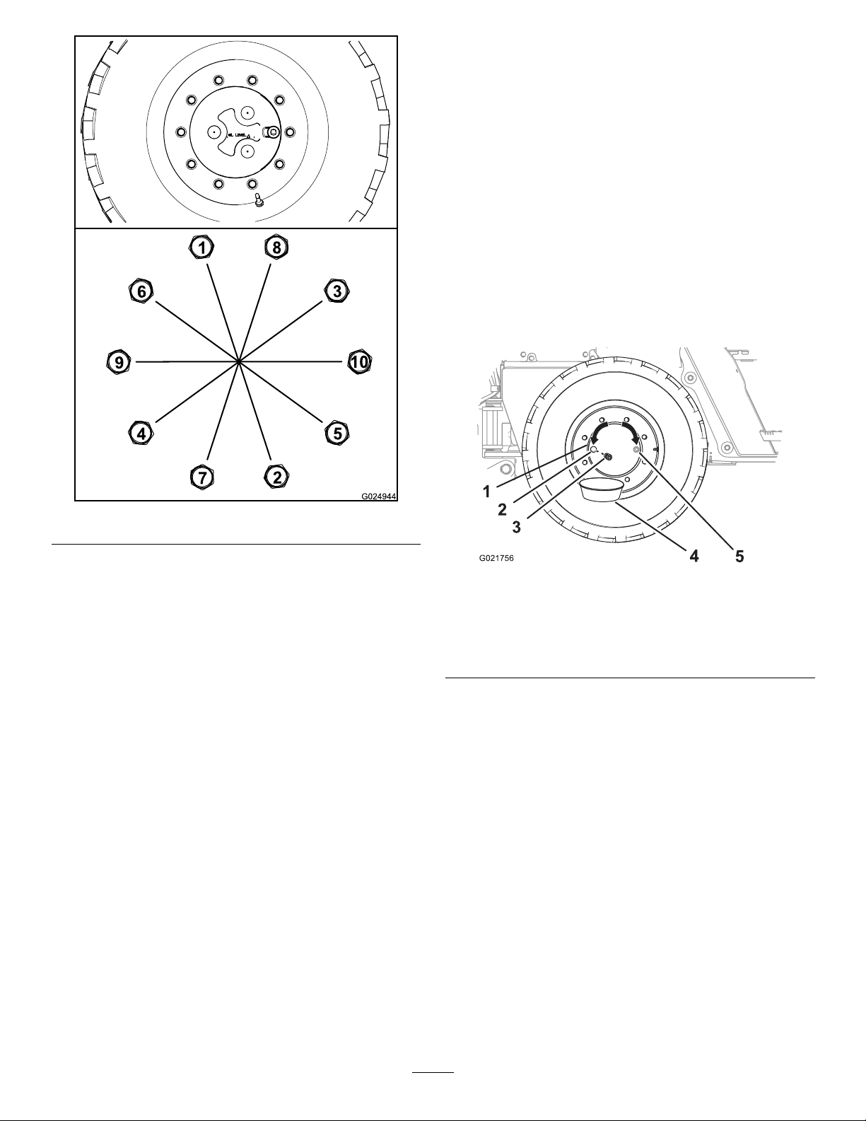
ServicingtheAxles
Hub-and-axleoilspecication:Mobiluid424
CheckingtheOilLevelintheWheel
Hubs
ServiceInterval:Aftertherst100hours
Every250hours
Note:Haveanotherpersonhelpyoualigntheoilplugsin
theaxleswhenyouservicetheaxleoil.
1.Ensurethatthemachineisonalevelsurfaceandthat
alltheattachmentsareinthetransportposition.
2.Movethemachineforwardorbackwarduntiltheplug
forthewheelhubisateitherthe3o’clockor9o’clock
position(Figure83).
Figure82
B.Torqueallthenutsto200N-m(150ft-lb)inthe
sequenceshowninFigure82.
C.Torqueallthenutsto300N-m(225ft-lb)inthe
sequenceshowninFigure82.
Figure83
1.Wheelhub4.Drainpan
2.Oilportatthe9o’clock
position
3.Plug
3.Stoptheengine,settheparkingbrake,andremovethe
ignitionkey .
4.Placeadrainpanunderthedrainportinthewheelhub
(Figure83).
5.Removetheplugfromthewheelhub(Figure83).
6.Checkthattheoillevelisatthebottomofthethreads
oftheoilport(Figure83).
5.Oilportatthe3o’clock
position(alternative)
•Iftheoillevelistoohigh,allowtheoiltodrain
fromtheoilport.
•Iftheoillevelistoolow,addthespeciedoiltothe
wheelhubthroughtheoilport;refertostep6in
ChangingtheOilintheWheelHubs(page57).
7.ChecktheconditionoftheO-ringontheplug.
Note:ReplacetheO-ringifitiswornordamaged.
8.Installtheplugintheoilportofthewheelhub(Figure
83).
9.Repeatsteps2through8fortheotherwheelhubs.
56
Page 57

ChangingtheOilintheWheelHubs
7.Installtheplugintheoilportofthewheelhub.
ServiceInterval:Aftertherst200hours
Every1,000hours
Wheelhuboilcapacity:approximately1.5L(1.6USqt)
ToroPremiumGearOilisavailablefromanAuthorizedToro
ServiceDealer.Seethepartscatalogforpartnumbers.
Note:Ifpossible,changetheoilwhenitiswarm.
1.Movethemachineforwardorbackwarduntiltheoil
plugforthewheelhubisatthe6o’clockposition
(Figure84).
8.Repeatthisprocedurefortheotherwheelhubs.
CheckingtheOilLevelintheAxles
ServiceInterval:Aftertherst100hours
Every250hours
1.Placeadrainpanunderthepinionhousingoftheaxle.
2.Removetheplugsfromthesightportinthepinion
housingoftheaxle(Figure85andFigure86).
Figure84
1.Wheelhub
2.Oilportatthe6o’clock
position
3.Drainpan
4.Oilportatthe3o’clock
position
5.Plug
6.Oil-servicingequipment
2.Placeadrainpanundertheoilportofthewheelhub
(Figure84).
3.Removethepluganddraintheoilfromtheplanetary
(Figure84).
4.ChecktheconditionoftheO-ringfortheplug.
Note:ReplacetheO-ringifitiswornordamaged.
5.Movethemachineforwardorbackwarduntiltheoil
plugforthewheelhubiseitheratthe3o’clockorthe9
o’clockposition(Figure84).
6.Addthespeciedoiltothewheelhubthroughtheoil
portuntiltheoillevelisatthebottomofthethreads
oftheport.
1.Front-axlehousing
2.Plug
Figure85
FrontAxle
3.Sightport
57
Page 58

Figure86
RearAxle
1.Rear-axlehousing3.Plug
2.Forward
4.Siteport
3.Lookthroughthesightportandcheckthattheoillevel
intheaxleislevelwiththebottomofthethreadsof
theport(Figure85andFigure86).
Note:Useaashlightandamirrortohelpyousee
theoillevel.
•Iftheoillevelistoohigh,allowtheoiltodrain
fromthesightport.
•Iftheoillevelistoolow,addthespeciedoilto
theaxlehousingsightport;refertosteps6and7in
ChangingtheOilintheAxles(page58).
4.Cleanthethreadsofthesightplug.
5.ApplyPTFEthreadsealingtapetothethreadsofthe
plug.
6.Installthesightplugintothesightportinthepinion
housingoftheaxle(Figure85andFigure86).
ChangingtheOilintheAxles
ServiceInterval:Aftertherst200hours
Every1,000hours
Figure87
FrontAxle
1.Drainplug3.Drainport
2.Drainpan4.Front-axlehousing
Figure88
RearAxle
1.Drainplug3.Drainport
2.Drainpan4.Rear-axlehousing
2.Removetheplugsfromthesightportandthedrain
portofthepinionhousingsfortheaxles(Figure87
andFigure88).
Note:Allowtheoiltodraincompletelyfromthe
pinionhousingandaxle.
3.Cleanthethreadsoftheplugs.
4.ApplyPTFEthreadsealingtapetothethreadsofthe
plugs.
5.Installthedrainplugsintothedrainportsatthepinion
housings(Figure89andFigure90).
Frontaxleoilcapacity:approximately9L(9.5USqt)
Rearaxleoilcapacity:approximately9L(9.5USqt)
ToroPremiumGearOilisavailablefromanAuthorizedToro
ServiceDealer.Seethepartscatalogforpartnumbers.
1.Placeadrainpanunderthepinionhousingoftheaxle
(Figure87andFigure88).
58
Page 59

Figure89
FrontAxle
Figure90
RearAxle
1.Front-axlehousing4.Pinionhousing
2.Oil-servicingequipment5.Sightport
3.Fillplug
1.Rear-axlehousing4.Fillplug
2.Forward
3.Oil-servicingequipment
5.Sightport
6.Filltheaxleswiththespeciedoilthroughthesight
portuntiltheoilislevelwiththethreadsatthebottom
oftheport(Figure89andFigure90).
7.Waitafewminutesfortheoiltosettle,thenaddmore
oilasnecessary.
Note:Continuetoaddoiluntiltheoillevelstabilizes
andisatthebottomofthethreadsofthesightport.
8.Installthellplugsintothesightportsofthepinion
housingsfortheaxles(Figure89andFigure90).
59
Page 60
CleaningtheAxleBreathers
ServicingtheTransmission
ServiceInterval:Every1,000hours
1.Cleantheareaaroundthebreatherswithacleaning
solvent(Figure91andFigure92).
Figure91
1.Breathertting
2.Frontaxle
Transmission-oilspecication:Mobiluid424
CheckingtheOilLevelinthe
Transmission
ServiceInterval:Every100hours
Important:Ifyouoperatethemachinewhilethelevelof
thetransmissionoilisbelowtherecommendedlevel,you
maydamagethetransmissionandtheparkingbrake.
1.Parkthemachineonalevelsurface.
2.Starttheengineandrunitfor10minutes.
3.Stoptheengineandremovetheignitionkey.
4.After5minutes,checkthetransmissionoillevelinthe
sightgauge(Figure93).
Note:Theoillevelshouldcover1/2to3/4ofthe
sight-gaugewindow .
Figure92
1.Breathertting
2.Removethebreathersfromthefrontaxleandrear
axles(Figure91andFigure92).
3.Cleanthebreatherswithacleaningsolvent.
4.Usecompressedairtodrythebreathers.
Important:Wearfaceprotectionwhenusing
compressedair.
5.Installthebreathersintothefrontandrearaxles(Figure
91andFigure92).
2.Rearaxle
Figure93
1.Sightgauge
5.Iftheoillevelislow ,addthespeciedoilintothe
transmission;refertoFillingtheTransmissionwithOil
(page61).
6.Repeatsteps2through5untiltheoillevelcovers1/2
to3/4ofthesight-gaugewindow(Figure93).
Note:Asyouaddoiltothetransmission,perform
steps2through4todeterminethecorrectedoillevel.
60
Page 61

ChangingtheTransmissionOil
ServiceInterval:Every1,000hours
DrainingtheTransmissionOil
3.ApplyPTFEthreadsealingtapetothethreadsofthe
plug.
4.Fillthetransmissionwiththespeciedoilthroughthe
llport(Figure95).
Note:Ifpossible,draintheoilwhenitiswarm.
1.Parkthemachineonalevelsurface,stoptheengine,
andremovethekey.
2.Placeadrainpanundertheforwardholeinthe
transmissionshield(Figure94).
Important:Whenyoullthetransmissionwith
oil,slowlyaddtheoilintothetransmissionto
avoidentrainingairwiththeoil.
Figure95
1.Oil-servicingequipment
2.Fillport
3.Fillplug
Figure94
1.Transmissionshield3.Drainplug
2.Drainpan
3.Throughthetransmissionshield,cleantheareaaround
thetransmissiondrainplug(Figure94).
4.Removethedrainplugandallowthetransmissionto
draincompletely.
5.Cleanthethreadsoftheplug.
6.ApplyPTFEthreadsealingtapetothethreadsofthe
plug.
7.Throughthetransmissionshield,securelyinstallthe
drainplugintothedrainportofthetransmission.
FillingtheTransmissionwithOil
Transmissionoilcapacity:approximately10L(10.6US
qt)—withlterchange
Important:Ifyouoperatethemachinewhilethelevelof
thetransmissionoilisbelowtherecommendedlevel,you
maydamagethetransmissionandtheparkingbrake.
5.Installthellplugintothellportsecurely
6.Starttheengineandrunitfor10minutes.
7.Stoptheengineandremovethekey.
8.After5minutes,checktheoillevelinthesightgauge.
Note:Theoillevelshouldcover1/2to3/4ofthe
sight-gaugewindow(Figure93).
Note:Asyouaddoiltothetransmission,perform
steps6through8todeterminecorrectedoillevel.
1.Removethellplugfromthellportofthe
transmission.
2.Cleanthethreadsoftheplug.
61
Page 62

ChangingtheTransmissionFilter
ServiceInterval:Every500hours
Note:Youcanaccessthetransmissionlterfromunderneath
therightsideofthemachine,inboardofthehydraulictank.
1.Placeadrainpanunderthetransmission-oillter
(Figure96).
9.Checkthetransmissionoillevel;ifthelevelislow,add
thespeciedoiltothetransmission;refertoFillingthe
TransmissionwithOil(page61).
Important:Whenyoullthetransmissionwith
oil,slowlyaddtheoilintothetransmissionto
avoidentrainingairwiththeoil.
Figure96
1.Forward
2.Transmission-oillter
3.Sharpobject
4.Drainpan
2.Puncturethebottomofthetransmissionlter,and
allowtheresidualhydraulicuidtodrainintothedrain
pan(Figure96).
Note:Useatapered-centerpunchorawltopuncture
theltercase
3.Removethetransmissionlterwithalterwrenchand
discardthelter(Figure96).
4.Wipecleantheoillteradapterattheseatingsurface
forthelter.
5.ApplyathinlayerofcleangreaseoroilontotheO-ring
ofthenewlter.
6.Installthenewlterbyhandandtightthelter1/2
to3/4turnafteritmakescontactwiththelterhead
(Figure96).
Important:Donotusealterstrapwrenchto
tightenthelter.Astrapwrenchcandentthe
lter,causingittoleak.
7.Starttheengineandrunitatidlefor1minute,and
checkforleaks.
8.Stoptheengineandremovethekey.
62
Page 63

CoolingSystem
Maintenance
ServicingtheCoolingSystem
2.Allowtheenginetocool.
3.Removetheleftsidepanel;refertoRemovingtheSide
Panels(page44).
4.Checkthecoolantlevelbylookingatthesightgaugein
thesideofthesurgetank(Figure97).
Coolantspecication:amixtureof50%ethyleneglycol
and50%water
Note:Anantifreezehavingamixtureof50%ethylene
glycoland50%waterwillprotecttheengineto-37°C(-34°F)
throughouttheyear.
Engineandradiatorcoolantcapacity:18.5L(19.5USqt)
Important:Usingover-concentratedorhigh-silicate
antifreezecandamagetheengine.
WARNING
Ifyouremovetherecovery-tankcapfromahot
engine,hotcoolantcouldspray,causingscalding.
•Wearfaceprotectionwhenopeningtheradiator
cap.
•Allowthecoolingsystemtocooldowntobelow
50°C(120°F)beforeremovingtherecovery-tank
cap.
•Followtheinstructionsforcheckingand
maintainingtheenginecoolingsystem.
WARNING
Note:Youshouldseethatthecoolantlevelisabove
themidpointofthesightgauge.
Figure97
1.Reservoirdoor4.Fillerneck
2.Hex-headbolt5.Recovery-tankcap
3.Coolantsightgauge
Coolantistoxic.
•Keepcoolantawayfromchildrenandpets.
•Ifyouarenotre-usingthecoolant,disposeofit
accordingtolocalenvironmentalregulations.
CheckingtheCoolantLevel
ServiceInterval:Every50hours
WARNING
Iftheenginehasbeenrunning,theradiatorwillbe
pressurizedandthecoolantinsidewillbehot.If
youremovethecap,coolantmaysprayout,causing
severeburns.
•Donotremovetherecovery-tankcaptocheck
coolantlevels.
•Donotremovetherecovery-tankcapwhenthe
engineishot.Allowtheenginetocoolforat
least15minutesoruntiltheradiatorcapiscool
enoughtotouchwithoutburningyourhand.
1.Parkthemachineonalevelsurface,stoptheengine,
andremovetheignitionkey.
5.Ifthecoolantlevelislow,preformthefollowing:
A.Removethe2hex-headboltsthatsecuretheto
thehoodofthemachine,andopenthereservoir
door(Figure97).
B.Removetherecovery-tankcapfromtherecovery
tank,andaddcoolantuntilthelevelisuptothe
midpointofthesightgauge(Figure97).
Important:Donotoverllthesurgetank
Note:Ifcoolantlevelislow ,checkforleaksin
thehoses,radiator,andtherecoverytank.
C.Installtherecovery-tankcap,ensuringthatitis
tightlysealed.
D.Closethereservoirdoorandsecureitwiththe2
hex-headboltsthatyouremovedinstepA.
6.Iftheairtemperatureisbelow0°C(32°F),mixthe
ethyleneglycolandwatercompletelybyrunningthe
engineatoperatingtemperaturefor5minutes.
7.Installtheleftsidepanel;refertoInstallingtheSide
Panels(page45).
63
Page 64
CheckingtheConditionofCooling
SystemComponents
ServiceInterval:Every300hours
Checktheconditionofthecoolingsystemforleaks,damage,
dirt,andloosehoses,andclamps.Clean,repair,tighten,and
replacethecomponentsasnecessary.
CheckingtheConcentrationofthe
Coolant
ServiceInterval:Every1,000hours
Testtheconcentrationofethyleneglycolbasedantifreezein
thecoolant.Ensurethatthecoolantisamixtureof50%
ethyleneglycoland50%water.
CleaningtheCoolingSystem
ServiceInterval:Every2,000hours/Every2years
(whichevercomesrst)
Thecoolantcapacityoftheengineandtheradiator:18.5
L(19.5USqt).
DrainingtheCoolantfromtheSystem
Important:Donotpourcoolantontothegroundorinto
anunapprovedcontainerthatcanleak.
1.Removetheleftandrightsidepanels;referto
RemovingtheSidePanels(page44).
2.Removethe2hex-headboltsthatsecurethereservoir
doortothehoodandopenthedoor(Figure97).
3.Removetherecovery-tankcapfromthetank(Figure
97).
4.Slipacoolantresistanthosethatis3/8x30inchesover
theoutletforthedrainvalveintheradiator(Figure98).
Figure98
1.Drainvalve
2.Hoseclamp
3.Drainhose(coolant
resistant)
5.Securethehosetothedrainvalvewithahoseclamp
(Figure98).
6.Routethehosedownandthroughtheholeinthelower
mountingplateforthebackllblade(Figure99).
Figure99
1.Frontofthemachine4.Drainhose(coolant
2.Up5.Drainpan—minimum
3.Hole(lowermounting
plate)
resistant)
capacityof23L(6gallons)
7.Placeadrainpanwithaminimumcapacityof23L(6
gallons)undertheopenendofthedrainhose(Figure
99).
8.Openthedrainvalveontheradiator,andallowthe
coolanttodraincompletely.
64
Page 65

Note:Disposeoftheusedcoolantproperlyaccording
tolocalcodes.
Figure100
1.Drainvalve
9.Closethedrainvalve(Figure100).
10.Removethedrainhoseandclamp(Figure98and
Figure99).
FlushingtheCoolingSystem
Engineandradiatorcoolantcapacity:18.5L(19.5USqt)
1.Conditionthecoolingsystemasfollows:
A.Ensurethatthecoolantisdrainedfromthe
radiatorandthatthedrainvalveisclosed(Figure
100).
B.Addacoolingsystemcleaningsolutiontotheto
thecoolingsystemthroughthellerneckofthe
recoverytank(Figure101).
Note:Usecleaningsolutionofsodiumcarbonate
andwater(oracommerciallyavailableequivalent).
Followthedirectionsthatcomewiththecleaning
solution.
Figure101
1.Reservoirdoor3.Funnel
2.Fillerneck(recoverytank)4.Coolantsystemcleaning
solution
C.Operatetheenginefor5minutesoruntilthe
coolanttemperatureinthecommand-center
displayindicates82°C(180°F),thenstopthe
engine(Figure102).
Important:Donotinstalltherecovery-tank
cap.
Figure102
1.180°Fwatertemperature(command-centerdisplay)
CAUTION
Thecleaningsolutionishotandcan
causeburns.
Stayawayfromthedischargeendofthe
coolantdrainhose.
65
Page 66
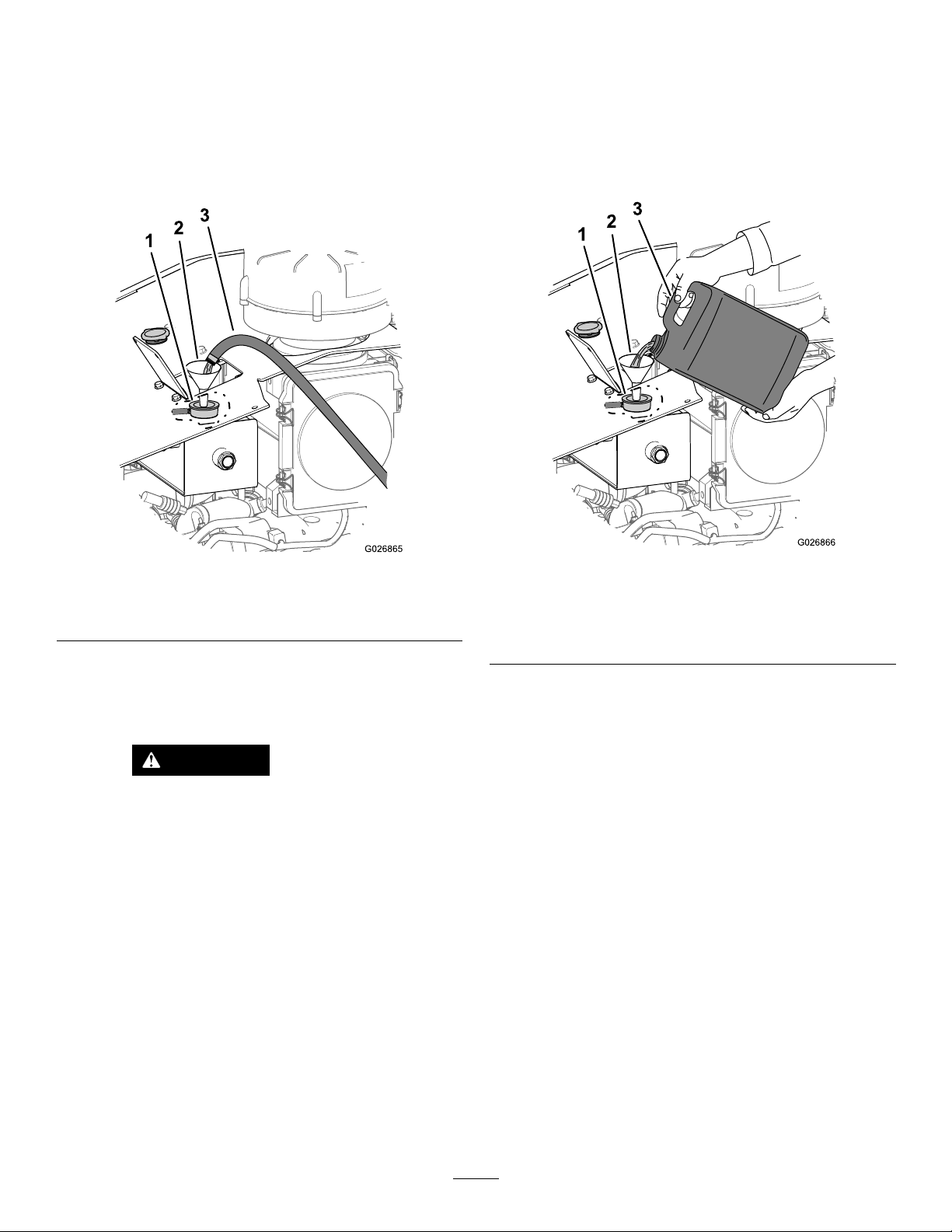
D.Openthedrainvalveanddrainthecleaning
solutionintoadrainpan(Figure98andFigure
100).
E.Closethedrainvalve(Figure100).
coolingsystemproperlycandamageboththeengine
andthecoolingsystem.
1.Removetheradiatorcapfromtherecoverytank
(Figure97).
2.Flushthecoolingsystemasfollows:
A.Fillthecoolingsystemwithcleanwater(Figure
103).
Figure103
1.Fillerneck(recoverytank)3.Cleanwater
2.Funnel
B.Operatetheenginefor5minutesoruntilthe
coolanttemperatureinthecommand-center
displayindicates82°C(180°F),thenstopthe
engine.
CAUTION
Thewaterishotandcancauseburns.
2.Fillthecoolingsystemwiththespeciedcoolant
mixture(Figure104)untiltheuidlevelisuptothe
midpointinthesightgauge(Figure97).
Figure104
1.Coolantlevel(midpointin
thesightgauge)
2.Funnel
3.Coolant(amixtureof50%
ethyleneglycoland50%
water)
3.Installtherecovery-tankcap(Figure97).
4.Starttheengineandrunitathalfthrottlefor5minutes.
5.Stoptheengineandremovethekey.
6.Wait30minutes,thenchecktheuidlevelinthe
recoverytank.Ifitislow,addcoolant.
Stayawayfromthedischargeendofthe
coolantdrainhose.
C.Openthedrainvalve(Figure100)anddrainthe
waterintoadrainpan.
D.Ifthewaterdrainedfromtheradiatorisdirty,
performsteps2-Athrough2-Cuntilthewater
drainedfromtheradiatorisclean.
E.Closethedrainvalve(Figure100).
FillingtheSystemwithCoolant
Thecoolantcapacityoftheengineandtheradiator:18.5
L(19.5USqt).
Important:Fillthecoolingsystemproperlytoprevent
airlocksinthecoolingpassages.Failingtoventthe
7.Closethereservoirdoorandsecureittothehoodwith
the2hex-headbolts(Figure97)thatyouremovedin
step2ofDrainingtheCoolantfromtheSystem(page
64).
8.Installthesidepanels;refertoInstallingtheSidePanels
(page45).
66
Page 67

BeltMaintenance
ServicingtheEngineDrive Belt
WARNING
Stoptheengineandremovethekeyfromthe
keyswitchbeforeyoubegintoperformany
maintenanceorrepairwork.
WARNING
Contactingarotatingbeltcancauseseriousinjury
ordeath.
Alwaysstoptheengineandremovethekeyfromthe
keyswitchbeforeworkingnearbelts.
Figure105
1.Belttensioner
3.Removethebeltfromthepulleys.
CheckingtheConditionoftheBelt
ServiceInterval:Every250hours
1.Removetheright-sidepanel;refertoRemovingthe
SidePanels(page44).
2.Inspectthebeltforcuts,cracks,loosecords,grease,oil,
twisting,orsignsofabnormalwear.
Note:Replacethebeltifitisexcessivelywornor
damaged;refertoReplacingtheEngineDriveBelt
(page67).
3.Installtheright-sidepanel;refertoInstallingtheSide
Panels(page45).
ReplacingtheEngineDrive Belt
RemovingtheBelt
1.Removetherightsidepanel;refertoRemovingthe
SidePanels(page44).
2.Loosenthetensiononthebeltbyrotatingthebelt
tensionerclockwise(Figure105).
Important:Thebelttensionerisspringloaded
andmustpivotawayfromthedrivebelt.Pivoting
thebelttensionerinthewrongdirectioncould
damageit.Also,donotuseexcessiveforcein
theoppositedirectionofwinduporafteryou
havewoundupthetensionertothepositivestop;
otherwise,thetensionerarmmaybreak.
CleaningandInspectingtheBeltand
thePulleys
1.Inspectthebeltforexcessivewearanddamage.
Replacethebeltunderanyofthefollowingconditions:
•Thebeltisfrayed,punctured,orsomeofits
materialismissing.
•Thereisembeddeddebrisinthegroovesoronthe
backsideofthebelt.
•Theribsareunevenorexcessivelyworn.
•Thebacksideofthebeltisglazedfromhighheat.
•Thereareexposedbeltcords.
Note:Youcanreuseabeltwithtransversecracks
(acrossthebelt)areacceptable,butreplaceabeltwith
longitudinalcracks(inthedirectionoftheribs)that
intersectwithtransversecracks.
2.Cleantheidlerandthedrivepulleys,andinspectthem
forwearorcracks.
Note:Replaceanypulleysthataredamaged,
deformed,orexcessivelyworn.
InstallingtheBelt
1.Routethebeltontothepulleys,butdonotinstallthe
beltoverthebelttensioner(Figure105).
2.Rotatethebelttensionerclockwiseandinstallthebelt
byslippingthebeltoverthebelttensioner.
3.Slowlyreleasethebelttensionertoapplytensionto
thedrivebelt.
4.Ensurethatthebeltisalignedwiththebelttensioner
andinthegroovesofthepulleys.
67
Page 68
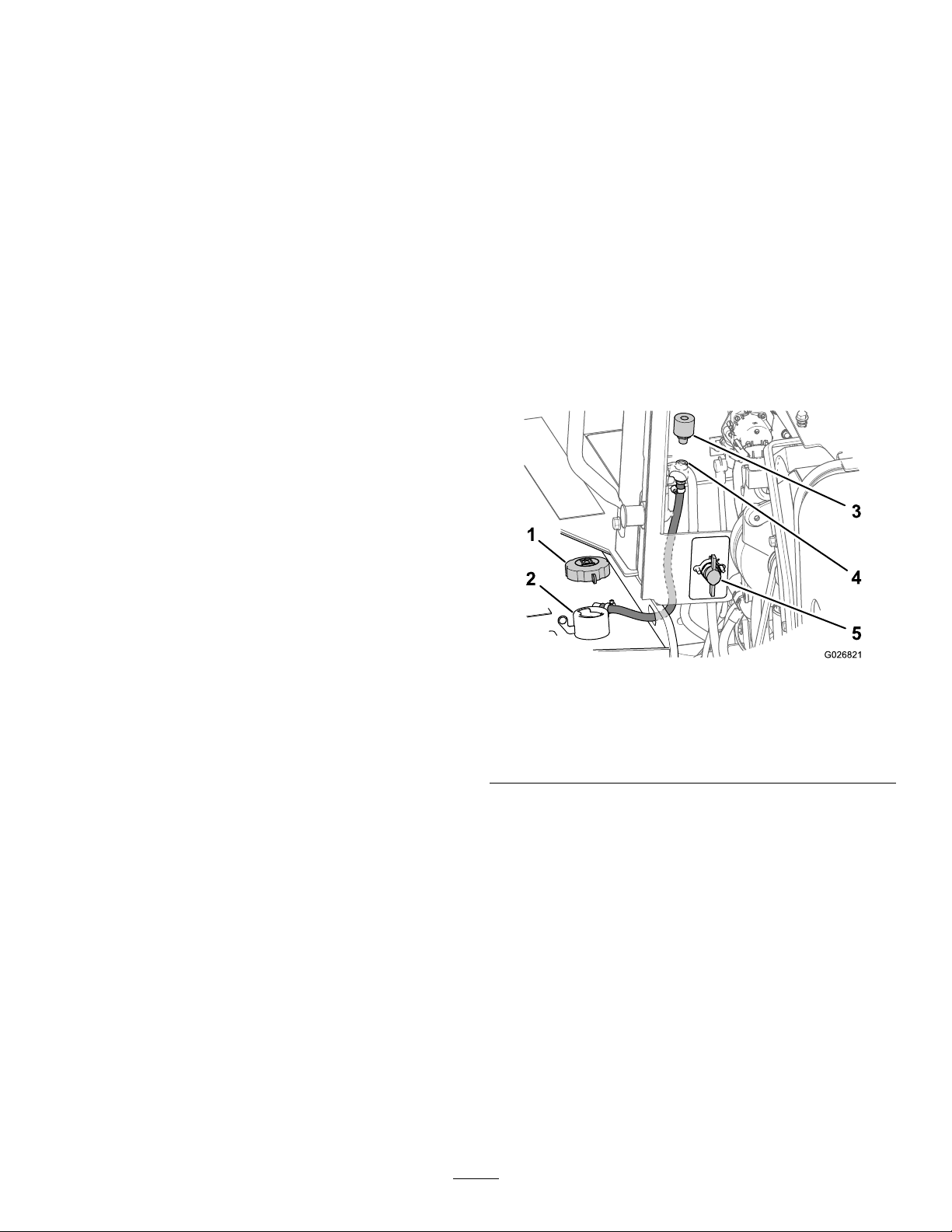
HydraulicSystem
Maintenance
ServicingtheHydraulic
ChangingtheHydraulicFluidand
ReplacingtheBreather
ServiceInterval:Every1,000hours
Thecapacityofthehydraulic-uidreservoir:150L(40
USgallons)
System
Hydraulic-uidspecication:ToroPremiumAll-season
HydraulicFluid
IfToroPremiumAll-seasonHydraulicFluidisnotavailable,
youmayuseMobilDTE15MSpecial(MobilDTE15Muid
withspecialantiwearadditivepackage).
Note:ToroPremiumAll-seasonHydraulicFluidisavailable
in5-gallonpailsor55-gallondrums.Seethepartscatalogor
anAuthorizedT oroServiceDealerforpartnumbers.
Themachinecomesfromthefactorywithafullhydraulic
uidreservoirthatcontainsapproximately182L(48US
gal)ofhigh-qualityhydraulicuid.Checkthelevelofthe
hydraulicuidbeforeyoustarttheenginefortherst
time,anddailythereafter.
Note:T orodoesnotassumeresponsibilityfordamage
causedbyimpropersubstitutions,souseonlyproductsfrom
reputablemanufacturers.
Note:Manybrandsofhydraulicuidsarealmostcolorless,
makingitdifculttospotleaks.Areddyeadditiveforthe
hydraulicsystemoilisavailablein20ml(0.68oz)bottles.
Onebottleissufcientfor15.1to22.7L(4.0to6.0USgal)
ofhydraulicoil.Orderpartno.44-2500fromanAuthorized
ToroServiceDealer.
Thecapacityofthehydraulic-uidsystem:182L(48
USgallons)
DrainingtheHydraulicReservoir
Note:Drainthehydraulicuidreservoirwhentheuidis
warm,ifpossible.
1.Removetherightsidepanel;refertoRemovingthe
SidePanels(page44).
2.RotatethebatterydisconnecttotheOffposition
(Figure106).
Figure106
Note:Ifambientoperatingtemperaturesexceed110°F ,
contactT oroforuidrecommendations.
1.Fillcap(hydraulictank)
2.Fillerneck(hydraulictank)
3.Breather
3.Removethellcapfromthellerneckofthetank
(Figure106).
4.Attheforwardsideoftheenginecompartmentpanel,
removethebreatherfromthepipecouplingbyrotating
thebreathercounterclockwise(Figure106).
Note:Discardtheoldbreather.
5.Installanewbreatherintothepipecouplinghandtight
(Figure106).
6.Placeacontainerthatcanholdaminimumof190L
(50USgal)underthehydraulicreservoirdrainplug
(Figure107).
4.Pipecoupling
5.Batterydisconnectswitch
(Offposition)
68
Page 69

Figure107
1.Fillcap3.Plug
2.Sightgauge(hydraulic
reservoir)
4.Drainpan
7.Removethedrainplugfromthehydraulicreservoir
(locatedunderneaththereservoir),anddrainthe
reservoir(Figure107).
8.Examinetheconditionofthesealonthedrainplug.
Note:Replacethesealifitiswornordamaged.
9.Installthedrainplug(Figure107).
Important:Changethehydraulic-pressure
andhydraulic-returnlterswhenyouchange
thehydraulicuid;refertoChangingthe
Hydraulic-chargeFilter(page70)andChanging
theHydraulic-returnFilter(page71).
10.RotatethebatterydisconnectswitchtotheOn
positionandinstalltherightsidepanel;referto
Battery-DisconnectSwitch(page20)andInstallingthe
SidePanels(page45).
FillingtheHydraulic-uidReservoir
1.Fillthehydraulic-uidreservoirwiththespecied
hydraulicuiduntiltheuidlevelisatthemidpointof
thesightgauge(Figure108).
Figure108
1.Filllevel(midpoint)3.Hydraulicuid
2.Sightgauge
2.Cleanthellcapwithsolvent.
3.Installthellcap(Figure108).
4.Starttheengineandletitidleforapproximately2
minutes.
5.Stoptheengineandremovethekeyfromthekey
switch.
6.Checkaroundthepressureandreturnltersforleaks.
7.Checkthedrainplugforleaks.
8.Checkthelevelofthehydraulicuid.
69
Page 70

ChangingtheHydraulicFilters
RemovingtheTraction-pedalAssembly
Removethetraction-pedalassemblyasfollows:
1.Removethe4hex-angedheadboltsthatsecurethat
traction-pedalassemblytothechassisofthemachine
(Figure109).
Figure110
Figure109
1.Hex-angedheadbolts
2.Traction-pedalassembly4.6-socketconnector
3.6-pinconnector
(traction-pedalsensor)
(machineharness)
2.Disconnectthe6-socketconnectorofthemachine
harnessfromthe6-pinconnectorofthetraction-pedal
sensor(Figure109).
3.Removethetraction-pedalassemblyfromthemachine
(Figure109).
ChangingtheHydraulic-chargeFilter
ServiceInterval:Every500hours
Note:Changethehydraulic-returnlterwhenyouchange
thehydraulic-chargelter.
Note:Youcanaccessthehydraulic-chargelterfromunder
therightsideofthemachine,behindthehydraulicreservoir
(Figure110).
1.Removethetraction-pedalassembly;refertoRemoving
theTraction-pedalAssembly(page70).
2.Placeacontainerunderthehydraulic-chargelter
(Figure110).
1.Containersuitablefor
hydraulicuid
2.Sharpobject
3.Hydraulic-chargelter
3.Rotatethehydraulic-chargeltercounterclockwiseand
removethelter(Figure110).
Note:Discardthelter.
4.Applyathinlayerofthespeciedhydraulicuidto
theO-ringofthenewlter.
Important:Donotusealterstrapwrenchto
tightenthelter.Astrapwrenchcandentthe
lter,causingittoleak.
5.Fillthenewchargelterwiththespeciedhydraulic
uid,allowthelterelementtosaturatewiththeuid,
andthenpourouttheexcessuid.
6.Installthenewlter.
Note:Useyourhandstotightenthelteranadditional
halfturnaftertheltermakescontactwiththelter
head.
7.Repeatsteps3through6fortheotherchargelter
8.Checkthelevelofthehydraulicuidinthehydraulic
reservoir;refertoCheckingtheHydraulic-FluidLevel
(page25).
9.Starttheengineandletitidlefor1or2minutes.
10.Shutofftheengine,andcheckforleaksaroundthe
lterarea.
11.Checkthelevelofthehydraulicuidinthehydraulic
reservoir,andadduid,ifnecessary;refertoFillingthe
Hydraulic-uidReservoir(page69).
70
Page 71

12.Installthetraction-pedalassembly;refertoRemoving
theTraction-pedalAssembly(page70).
Note:Useatapered-centerpunchorawltopuncture
theltercase.
InstallingtheTraction-pedalAssembly
1.Connectthe6-socketconnectorofthemachine
harnesstothe6-pinconnectorofthetraction-pedal
sensor(Figure109).
2.Aligntheholesintheplateofthetraction-pedal
assemblywiththeholesinthechassisofthemachine
(Figure109).
3.Securethetraction-pedalassemblytothechassisof
themachinewiththe4hex-angedheadbolts(6x25
mm);refertoFigure109.
ChangingtheHydraulic-returnFilter
ServiceInterval:Every500hours
Note:Changethehydraulic-chargelterwhenyouchange
thehydraulic-returnlter.
Note:Youcanaccessthehydraulic-returnlterfrom
underneaththerear-attachmentplateofthemachine(Figure
111).
1.Placeacontainerunderthehydraulic-returnlter
(Figure111).
3.Rotatethehydraulic-returnltercounterclockwiseand
removethelter(Figure111).
Note:Discardthelterproperly .
4.Applyathinlayerofthespeciedhydraulicuidto
theO-ringofthenewlter.
Important:Donotusealterstrapwrenchto
tightenthelter.Astrapwrenchcandentthe
lter,causingittoleak.
5.Installthenewlter.
Note:Useyourhandstotightenthelteranadditional
halfturnaftertheltermakescontactwiththelter
head.
6.Checkthelevelofthehydraulicuidinthehydraulic
reservoir;refertoCheckingtheHydraulic-FluidLevel
(page25).
7.Starttheengineandrunitatidlefor1or2minutes.
8.Stoptheengineandremovethekey.
9.Checkaroundthelterforleaks.
10.Checktheuidlevelofthehydraulicreservoir,andadd
uid,ifnecessary;refertoFillingtheHydraulic-uid
Reservoir(page69).
Figure111
1.Containersuitablefor
hydraulicuid
2.Sharpobject
3.Hydraulicreturnlter
4.Rear-attachmentplate
2.Puncturethebottomofthehydraulic-returnlter
andallowtheresidualhydraulicuidtodraininthe
container(Figure111).
71
Page 72

ROPSMaintenance
1
g024988
1
g024989
CheckingandServicingthe ROPS
AROPScerticationlabellocatedonthesupportstructure
containsinformationaboutthemaximumgrossmachine
weight,themachinemodelnumber,andtheISOnumber.
ReplacingaDamagedROPSSystem
IftheROPSsystemhasbeendamagedinanaccident,such
asarolloverorhittinganoverheadobjectduringtransport,
replaceanydamagedROPScomponentstorestoretheROPS
systemtoitsoriginallevelofprotection.
Important:Donottrytoweldorstraightenadamaged
ROPSbar.
Afteranaccident,checkthefollowingitemsfordamage:
•TheROPSbar
•Operatorseat
•Seatbeltmounting
•Seatbelt
Beforeyouoperatethemachine,replacealldamagedROPS
components;contactanAuthorizedToroServiceDealer.
CheckingandCaringfortheSeatBelt
Beforeyouoperatethemachine,alwaysensurethattheROPS
andtheseatbeltareproperlyinstalledandingoodworking
order.
1.Checktheseatbeltfordamage,andreplaceallparts
thataredamaged.
2.Ensurethatthemountingboltsfortheseatbeltsare
tight.
3.Keeptheseatbeltscleanusingonlysoapandwater.
Note:Donotimmersetheseatbeltsinbleachordye,
becausethisweakensthebeltmaterial.
Figure112
1.Bolts
2.Checkthattheboltsandnutsthatattachtheseat-belt
retractorandbuckletotheseataretorquedto47to61
N-m(35to45in-lb);refertoFigure113.
CheckingandMaintainingtheROPS
ServiceInterval:Every500hours
Important:IfanypartoftheROPSsystemisdamaged,
replaceitbeforeyouoperatethemachine.
1.Checkthattheboltsthatsecuretheseattothechassis
ofthemachinearetorquedto27to34N-m(20to25
in-lb);refertoFigure112.
Figure113
1.Bolts
Note:Replaceanypartsthatarewornordamaged.
3.InspecttheROPSforcracks,rust,orholesinthe
ROPSandcomponentparts.
Note:Age,weather,andaccidentscausedamageto
theROPSandROPSparts.Ifyouhaveanydoubts
abouttheROPSsystem,contactanAuthorizedToro
ServiceDealer.
72
Page 73

WeldingontheMachine
Important:Beforeyouuseanelectricweldertorepair
ormodifythemachine,performallthefollowing:
•Rotatethebattery-disconnectswitchtotheOffposition
•Disconnectthenegativeandpositivebatterycables.
•Disconnectthewiringatthealternator.
•Disconnectthe2connectorsforthecomputermodule.
•Disconnecttheconnectorforthecommand-center
display.
Afteryoucompleteweldingonthemachine,connectthe
command–centerdisplay,computermodule,alternator,and
batterycablesandrotatethe.battery-disconnectswitchto
theOnposition
PreparingtoDisconnectthe Components
1.Removetherightsidepanel;refertoRemovingthe
SidePanels(page44).
5.Usingthengerpulls,liftthebatterycoverupto
removeitfromtheROPSplatform(Figure114).
6.Removethelock-washernut(3/8inch)securingthe
negative-batterycableandringterminaltothenegative
studofthebatteryandremovethecablesfromthe
battery(Figure115).
2.Rotatethebattery-disconnectswitchtotheOff
position;refertoBattery-DisconnectSwitch(page20).
3.Removethe2nger-pullcoversfromtheholesinthe
batterycover(Figure114).
Note:Thebatterycoverislocatedbetweenthe
operatorseatandtherearROPSbulkhead.
Figure115
1.Positive-batterycable
2.Negative-batterycable
3.Ringterminal
7.Movebacktheinsulatorbootandremovethe
lock-washernut(3/8inch)securingthepositive-battery
cabletothepositivestudofthebatteryandremovethe
cablefromthebattery(Figure115).
4.Lock-washernut(3/8inch)
5.Negativestud(battery)
6.Positivestud(battery)
Figure114
1.Operatorseat4.Flange-headbolts(5/16x
1inch)
2.Finger-pullcover5.Nutclip
3.Hole(batterycover)6.ROPSbulkhead
4.Removethe4ange-headbolts(5/16x1inch)that
securethebatterycovertotheROPSplatform(Figure
114).
73
Page 74

DisconnectingtheAlternator Wiring
1.Atthealternator,slidethebootofftheterminaland
studatthebackofthealternator(Figure116).
Figure117
Figure116
1.Chargewire
2.Boot
2.Removethenutandwasherthatsecurestheterminal
ofthechargewiretothestudofthealternator,and
removetheterminal.
3.Removethe4-socketconnectorforthevoltage-sense
wirefromthe4-pinconnectorontopofthealternator
(Figure116).
3.4-socketconnector
(voltage-sensewire)
1.Lower-consolepanel
2.Disconnectthe50-socketconnector(CPU1)fromthe
backofthecomputermodule(Figure118).
2.Hex-angedheadbolts(6
x20mm)
Disconnectingthe Computer-moduleConnectors
1.Removethe4hex-angedheadbolts(6x20mm)that
securethelower-consolepaneltotheconsole,and
removethepanel(Figure117).
Figure118
1.Forward
2.50-socketconnector(CPU
1)
3.Disconnectthe38-socketconnector(CPU-2)fromthe
backofthecomputermodule(Figure118).
3.Computermodule
4.38-socketconnector
(CPU-2)
Connectingthe Computer-moduleConnectors
1.Connectthe38-socketconnector(CPU-2)totheback
ofthecomputermodule(Figure118).
2.Connectthe50-socketconnector(CPU1)totheback
ofthecomputermodule(Figure118).
74
Page 75

3.Alignthelower-consolepaneltotheconsole(Figure
117).
4.Securethepaneltotheconsolewiththe4hex-anged
headbolts(6x20mm).
ConnectingtheAlternator Wiring
1.Ensurethatthebattery-disconnectswitchisintheOff
position;refertoBattery-DisconnectSwitch(page20).
2.Connectthe4-socketconnectorforthevoltage-sense
wiretothe4-pinconnectorontopofthealternator
(Figure116).
3.Assembletheterminalofthechargewireontothestud
atthebackofthealternator(Figure116).
4.Securethechargewiretothestudwiththenutand
washer.
5.Alignthebootofthechargewireovertheterminal
andstud(Figure116).
ClosingtheMachine
Cleaning
RemovingDirtandDebrisfrom theMachine
Important:Operatingtheenginewithblockedscreens,
dirtyorpluggedcoolingns,and/orcoolingshrouds
removed,willresultinenginedamagefromoverheating.
1.Lowerallattachmentsandsettheparkingbrake.
2.Stoptheengine,removethekey,andwaitforallmoving
partstostopbeforeleavingtheoperatingposition.
3.Wipeawaydirtanddebrisfromtheaircleaner.
4.Cleananydirtanddebrisbuildupontheenginewitha
brushorblower.
Important:Itispreferabletoblowdirtout,rather
thanwashingitout.Ifwaterisused,keepitaway
fromelectricalitemsandhydraulicvalves.Do
notuseahigh-pressurewasher.High-pressure
washingcandamagetheelectricalsystemand
hydraulicvalvesordepletegrease.
1.Assemblethepositive-batterycableintothepositive
studofthebattery(Figure115)withthelock-washer
nut(3/8inch)thatyouremovedinstep7ofPreparing
toDisconnecttheComponents(page73).
2.Torquethelock-washernutto(10to15ft-lb)andalign
theinsulatorbootoverthenutandstud.
3.Assemblethenegative-batterycableintothenegative
studofthebattery(Figure115)withthelock-washer
nut(3/8inch)thatyouremovedinstep6ofPreparing
toDisconnecttheComponents(page73).
4.Aligntheholesinthebatterycoverwiththeclipnuts
atthemountingangeforthecover(Figure114).
5.Securethebatterycovertothemachinewiththe4
ange-headbolts(5/16x1inch)thatyouremovedin
step4ofPreparingtoDisconnecttheComponents
(page73).
6.Installthenger-pullcoverintotheholesinthebattery
cover.
7.Rotatethebattery-disconnectswitchtotheOn
position;refertoBattery-DisconnectSwitch(page20).
8.Installtherightsidepanel;refertoInstallingtheSide
Panels(page45).
75
Page 76

Storage
4.Stoptheengine.
5.Flushthefueltankwithfresh,cleandieselfuel.
PreparingforSeasonal Storage
Forstorageover30days,preparethemachine,the
attachments,andtheengineasfollows:
PreparingtheMachineand
Attachments
1.Thoroughlycleanthemachineandalltheattachments;
refertoRemovingDirtandDebrisfromtheMachine
(page75).
2.Loweralltheattachmentsandsettheparkingbrake.
3.Stoptheengine,removethekey,andwaitforallmoving
partstostopbeforeleavingtheoperatingposition.
4.Checkthetirepressureandadjustit,ifnecessary;refer
toMaintainingtheAirPressureintheTires(page55).
5.Checkallfastenersandtightenthemasnecessary.
6.Greaseallttingsandpivotpointsandwipeupany
excessgrease;refertoGreasingtheMachine(page42).
7.Repairanydentsinthemachineortheattachments,
andlightlysandandpaintareasthatarebare,scratched,
chipped,orrusted.Paintisavailablefroman
AuthorizedToroServiceDealer.
6.Secureallthefuelsystemttings.
7.Servicetheaircleaner;refertoServicingtheAir-cleaner
System(page47).
8.Sealtheaircleanerinletandtheexhaustoutletwith
plasticandweatherprooftape.
9.Checktheantifreezeprotectionandadda50%
ethyleneglycoland50%watersolutionofanti-freeze
asneededfortheexpectedminimumtemperaturein
yourarea.
8.Servicethebatteryandthecablesasfollows:
A.Removethebatteryterminalsfromthebattery
posts.
B.Cleanthebattery,terminals,andpostswithawire
brushandbakingsodasolution.
C.Coatthecableterminalsandbatterypostswith
Grafo112Xskin-overgrease(ToroPartNo.
505-47)orequivalentgrease.
D.Slowlyrechargethebatteryevery60daysfor24
hourstopreventleadsulfationofthebattery.
9.Checkandtightenallbolts,nuts,andscrews.Repairor
replaceanypartthatisdamaged.
10.Storethemachineinaclean,drygarageorstoragearea.
Removethekeyfromtheignitionswitchandkeepitin
amemorableplace.
11.Coverthemachinetoprotectitandkeepitclean.
PreparingtheEngine
1.Removedirt,grime,andchafffromtheexternalparts
oftheengine.
2.Changetheengineoilandtheoillter;referto
ChangingtheEngineOilandFilter(page45).
3.Starttheengineandrunitatidlespeedfor
approximately2minutes.
76
Page 77

Troubleshooting
Problem
Thestarterdoesnotcrank.
1.Theenginecranksbutwillnotstart.
PossibleCauseCorrectiveAction
1.Theelectricalconnectionsare
corrodedorloose.
2.Afuseisblown.2.Replacethefuse.
3.Afuseisloose.3.Installthefuse.
4.Thebatteryisdischarged.
5.Therelayorswitchisdamaged.
6.Thestarterorstartersolenoidis
damaged.
7.Internalenginecomponentshave
seizedup.
1.Thestartingprocedureisincorrect.
2.Thefueltankisempty .2.Fillthefueltankwithfreshfuel.
3.Thefuelshutoffvalveisclosed.3.Openthefuelshutoffvalve.
4.Thereisdirt,water,stalefuel,or
incorrectfuelinthefuelsystem.
5.Thefuellineisclogged.5.Cleanorreplacethefuelline.
6.Thereisairinthefuel.6.Bleedthenozzlesandcheckforair
7.Theglowplugsdonotoperate.
8.Thecrankingspeedisslow.
9.Theaircleaningsystemelementsare
dirty.
10.Thefuellterisclogged.10.Replacethefuellter .
11.Thefuelisnotthepropergradefor
cold-weatheruse.
12.Theenginehaslowcompression.
13.Theinjectionnozzlesorpumpare
malfunctioning.
1.Checktheelectricalconnectionsfor
goodcontact.
4.Chargethebatteryorreplaceit.
5.ContactyourAuthorizedService
Dealer.
6.ContactyourAuthorizedService
Dealer.
7.ContactyourAuthorizedService
Dealer.
1.RefertoStartingtheEnginein
Operation.
4.Drainandushthefuelsystem;add
freshfuel.
leaksatthefuelhoseconnections
andttingsbetweenthefueltankand
engine.
7.Checkthefuse,glowplugs,andwiring.
8.Checkthebattery,oilviscosity,and
startingmotor(contactyourAuthorized
ServiceDealer).
9.Servicetheaircleaningsystem
elements.
11.Drainthefuelsystem,replacethefuel
lter,andaddfreshfuelhavingthe
propergradeforambienttemperature
conditions.Youmayneedtowarmup
theentiremachine.
12.ContactyourAuthorizedService
Dealer.
13.ContactyourAuthorizedService
Dealer.
Theenginestartsbutdoesnotkeep
running.
1.Thefueltankventisrestricted.1.Loosenthecap.Iftheenginerunswith
2.Thereisdirtorwaterinthefuelsystem.2.Drainandushthefuelsystem;add
3.Thefuellterisclogged.3.Replacethefuellter.
4.Thereisairinthefuel.4.Bleedthenozzlesandcheckforair
5.Thefuelisnotthepropergradefor
cold-weatheruse.
6.Thefuelpumpisdamaged.6.ContactyourAuthorizedService
thecaploosened,replacethecap.
freshfuel.
leaksatfuelhoseconnectionsand
ttingsbetweenthefueltankandthe
engine.
5.Drainthefuelsystem,replacethefuel
lter,andaddfreshfuelhavingthe
propergradeforambienttemperature
conditions.Youmayneedtowarmup
theentiremachine.
Dealer.
77
Page 78

Problem
PossibleCauseCorrectiveAction
Theenginerunsbutknocksormisses.
Theengineisoverheated.
1.Thereisdirtorwaterinthefuelsystem.1.Drainandushthefuelsystem;add
2.Theengineoverheats.
3.Thereisairinthefuel.3.Bleedthenozzleandcheckforair
4.Theinjectionnozzlesaredamaged.
5.Theenginehaslowcompression.
6.Thereisexcessivecarbonbuildup.
7.Theenginehasinternalwearor
damage.
1.Thecoolantlevelistoolow .
2.Theairowtotheradiatorisrestricted.
3.Theengineoilleveliseithertoolowor
toohigh.
4.Themachineisunderanexcessive
load.
5.Thereisimproperfuelinthefuel
system.
6.Thethermostatisdamaged.
7.Theinjectiontimingisincorrect.
8.Thecoolantpumpisdamaged.
freshfuel.
2.Checktheengineoillevelandaddoil
asneeded;alsocheckandservicethe
coolantsystem,ifnecessary .
leaksatthefuelhoseconnectionsand
thettingsbetweenthefueltankand
theengine.
4.ContactyourAuthorizedService
Dealer.
5.ContactyourAuthorizedService
Dealer.
6.ContactyourAuthorizedService
Dealer.
7.ContactyourAuthorizedService
Dealer.
1.Checkthecoolantlevelandadd
coolanttothesystem.
2.Inspectandcleantheradiatorscreen.
3.Eitheraddordraintheengineoiluntil
theoillevelisattheFullmark.
4.Reducetheloadonthemachine;
operatethemachineataslower
groundspeed.
5.Drainandushthefuelsystem,then
addfreshfuel.
6.ContactyourAuthorizedService
Dealer.
7.ContactyourAuthorizedService
Dealer.
8.ContactyourAuthorizedService
Dealer.
Thereisexcessiveblacksmokeinthe
exhaust.
Thereisexcessivewhitesmokeinthe
exhaust.
1.Theaircleaningsystemelementsare
dirty.
2.Thereisimproperfuelinthefuel
system.
3.Theinjectionpumptimingisincorrect.
4.Theinjectionpumpisdamaged.
5.Theinjectionnozzlesaredamaged.
6.Theturbochargerisdamaged.
1.ThekeywasturnedtotheStartposition
beforetheglowpluglightturnedoff.
2.Theenginetemperatureislow.
3.Theglowplugsarenotoperating.
4.Theinjectionnozzlesaredamaged.
5.Theenginehaslowcompression.
6.Thereisaninternalcoolantleakinthe
engine.
1.Servicetheaircleaningsystem
elements.
2.Drainandushthefuelsystem,then
addfreshfuel.
3.ContactyourAuthorizedService
Dealer.
4.ContactyourAuthorizedService
Dealer.
5.ContactyourAuthorizedService
Dealer.
6.ContactyourAuthorizedService
Dealer.
1.TurnthekeytotheRunpositionand
allowtheglowpluglighttoturnoff
beforestartingtheengine.
2.Checkthethermostatandreplaceitif
necessary.
3.Checkthefuse,glowplugs,andwiring.
4.ContactyourAuthorizedService
Dealer.
5.ContactyourAuthorizedService
Dealer.
6.ContactyourAuthorizedService
Dealer.
78
Page 79

Problem
PossibleCauseCorrectiveAction
Theenginelosespower.
Themachinedoesnotdrive.
1.Theengineisunderanexcessiveload.
2.Theengineoilleveliseithertoolowor
toohigh.
3.Theaircleaningsystemelementsare
dirty.
4.Thereisdirtorwaterinthefuelsystem.4.Drainandushthefuelsystem;add
5.Theengineoverheats.
6.Thereisairinthefuel.6.Bleedthenozzleandcheckforair
7.Theenginehaslowcompression.
8.Thefueltankventisrestricted.8.Loosenthecap.Iftheenginerunswith
9.Theinjectionpumpisdamaged.
1.Theparkingbrakeisengaged.1.Releasetheparkingbrake.
2.Thehydraulicuidlevelislow.2.Addhydraulicuidtothereservoir.
3.Thepumpand/ormotorisdamaged.3.ContactyourAuthorizedService
4.Thereliefvalveisdamaged.4.ContactyourAuthorizedService
1.Reducethegroundspeedofthe
machine.
2.Eitheraddordraintheengineoiluntil
theoillevelisattheFullmark.
3.Servicetheaircleaningsystem
elements.
freshfuel.
5.Checktheengineoillevelandaddoil
asneeded;alsocheckandservicethe
coolantsystem,ifnecessary .
leaksatthefuelhoseconnectionsand
thettingsbetweenthefueltankand
theengine.
7.ContactyourAuthorizedService
Dealer.
thecaploosened,replacethecap.
9.ContactyourAuthorizedService
Dealer.
Dealer.
Dealer.
79
Page 80

TheToroUndergroundWarranty
ALimitedWarranty
Underground
Equipment
ConditionsandProductsCovered
TheToroCompanyanditsafliate,T oroWarrantyCompany,pursuant
toanagreementbetweenthem,jointlywarrantyourToroUnderground
Equipment(“Product”)tobefreefromdefectsinmaterialsorworkmanship.
Whereawarrantableconditionexists,wewillrepairtheProduct
atnocosttoyouincludingdiagnostics,labor,andparts.
ThefollowingwarrantyappliesfromthedatetheProductisdeliveredtothe
originalretailpurchaserorrentalowner.
ProductsWarrantyPeriod
EnginePoweredUnits&FluidMixers
AllSerializedAttachments
RockHammer6months
Engines
1yearor1000operatinghours,
whicheveroccursrst
1year
Throughenginemanufacturers:
2yearsor2000operatinghours,
whicheveroccursrst
InstructionsforObtainingWarrantyService
YouareresponsiblefornotifyingtheUndergroundDealerfromwhomyou
purchasedtheProductassoonasyoubelieveawarrantablecondition
exists.IfyouneedhelplocatingaUndergroundDealer ,orifyouhave
questionsregardingyourwarrantyrightsorresponsibilities,youmay
contactusat:
ToroCustomerCare
ToroWarrantyCompany
811 1LyndaleAvenueSouth
Bloomington,MN55420-1196
TollFreeat855-493-0088(U.S.Customers)
1-952-948-4318(InternationalCustomers)
OwnerResponsibilities
AstheProductowner,youareresponsibleforrequiredmaintenanceand
adjustmentsstatedinyourOperator'sManual.Failuretoperformrequired
maintenanceandadjustmentscanbegroundsfordisallowingawarranty
claim.
ItemsandConditionsNotCovered
Notallproductfailuresormalfunctionsthatoccurduringthewarranty
periodaredefectsinmaterialsorworkmanship.Thiswarrantydoesnot
coverthefollowing:
•Productfailureswhichresultfromtheuseofnon-T ororeplacement
parts,orfrominstallationanduseofadd-on,ormodiednon-Toro
brandedaccessoriesandproducts.Aseparatewarrantymaybe
providedbythemanufactureroftheseitems.
•Productfailureswhichresultfromfailuretoperformrecommended
maintenanceand/oradjustments.Failuretoproperlymaintainyour
ToroproductpertheRecommendedMaintenancelistedinthe
Operator’sManualcanresultinclaimsforwarrantybeingdenied.
•ProductfailureswhichresultfromoperatingtheProductinanabusive,
negligent,orrecklessmanner.
•Partssubjecttoconsumptionthroughuseunlessfoundtobedefective.
Examplesofpartswhichareconsumed,orusedup,duringnormal
Productoperationinclude,butarenotlimitedto:brakes,lters,lights,
bulbs,belts,tracksortires,diggingteeth,diggingbooms,digging,
drive,ortrackchains,trackpads,drivesprockets,idlers,rollers,
blades,cuttingedges,orothergroundengagingcomponents.
•Failurescausedbyoutsideinuence.Conditionsconsideredtobe
outsideinuenceinclude,butarenotlimitedto,weather,storage
practices,contamination,useofunapprovedfuels,coolants,lubricants,
additives,water,orchemicals,etc.
•Failureorperformanceissuesduetotheuseoffuels(e.g.gasoline,
diesel,orbiodiesel)thatdonotconformtotheirrespectiveindustry
standards.
•Normalnoise,vibration,wearandtear ,anddeterioration.
•Normal“wearandtear”includes,butisnotlimitedto,damagetoseats
duetowearorabrasion,wornpaintedsurfaces,scratcheddecals,etc.
•Haulingexpenses,traveltime,mileage,orovertimeassociatedwith
transportingproducttotheauthorizedT orodealer.
Parts
Partsscheduledforreplacementasrequiredmaintenanceinthe
Operator’sManual,arewarrantedfortheperiodoftimeuptothescheduled
replacementtimeforthatpart.Partsreplacedunderthiswarrantyare
coveredforthedurationoftheoriginalproductwarrantyandbecomethe
propertyofT oro.T orowillmakethenaldecisionwhethertorepairany
existingpartorassemblyorreplaceit.T oromayuseremanufacturedparts
forwarrantyrepairs.
MaintenanceisatOwner’sExpense
Enginetune-up,lubrication,cleaningandpolishing,replacementoflters,
coolant,andcompletingrecommendedmaintenancearesomeofthe
normalservicesT oroproductsrequirethatareattheowner’sexpense.
GeneralConditions
RepairbyanAuthorizedToroUndergroundDealerisyoursoleremedy
underthiswarranty.
NeitherTheToroCompanynorToroWarrantyCompanyisliablefor
indirect,incidentalorconsequentialdamagesinconnectionwiththe
useoftheToroProductscoveredbythiswarranty,includingany
costorexpenseofprovidingsubstituteequipmentorserviceduring
reasonableperiodsofmalfunctionornon-usependingcompletion
ofrepairsunderthiswarranty.ExceptfortheEmissionswarranty
referencedbelow,ifapplicable,thereisnootherexpresswarranty.All
impliedwarrantiesofmerchantabilityandtnessforusearelimitedto
thedurationofthisexpresswarranty.
Somestatesdonotallowexclusionsofincidentalorconsequential
damages,orlimitationsonhowlonganimpliedwarrantylasts,sotheabove
exclusionsandlimitationsmaynotapplytoyou.Thiswarrantygivesyou
speciclegalrights,andyoumayalsohaveotherrightswhichvaryfrom
statetostate.
Noteregardingenginewarranty:
TheEmissionsControlSystemonyourProductmaybecoveredby
aseparatewarrantymeetingrequirementsestablishedbytheU.S.
EnvironmentalProtectionAgency(EPA)and/ortheCaliforniaAirResources
Board(CARB).Thehourlimitationssetforthabovedonotapplytothe
EmissionsControlSystemWarranty.RefertotheEngineEmissionControl
WarrantyStatementsuppliedwithyourproductorcontainedintheengine
manufacturer’sdocumentationfordetails.
CountriesOtherthantheUnitedStatesorCanada
CustomerswhohavepurchasedT oroproductsexportedfromtheUnitedStatesorCanadashouldcontacttheirT oroDistributor(Dealer)toobtain
guaranteepoliciesforyourcountry ,province,orstate.IfforanyreasonyouaredissatisedwithyourUndergroundDealer’sserviceorhavedifculty
obtainingguaranteeinformation,contacttheToroimporter.
AustralianConsumerLaw:AustraliancustomerswillnddetailsrelatingtotheAustralianConsumerLaweitherinsidetheboxoratyourlocalT oro
Dealer.
374-0292RevB
 Loading...