

Page 1
FormNo.3398-100RevA
TiltSteeringKit
RT1200TractionUnit
ModelNo.25497
ModelNo.25497E
InstallationInstructions
Installation
WARNING
CALIFORNIA
Proposition65Warning
ThisproductcontainsachemicalorchemicalsknowntotheStateofCaliforniato
causecancer,birthdefects,orreproductiveharm.
1
PreparingtoInstallthe Tilt-SteeringColumn
NoPartsRequired
Procedure
1.Movethemachinetoalevelsurface.
Note:Ensurethatthefrontwheelsofthemachine
arestraight.
2.Settheparkingbrake,shutofftheengine,andremove
thekeyfromthekeyswitch.
3.Removetherightpanel;refertotheOperator’sManual.
4.Rotatethebattery-disconnectswitchtotheOFF
position;refertotheOperator’ sManual.
2
RemovingtheSteeringWheel
NoPartsRequired
Procedure
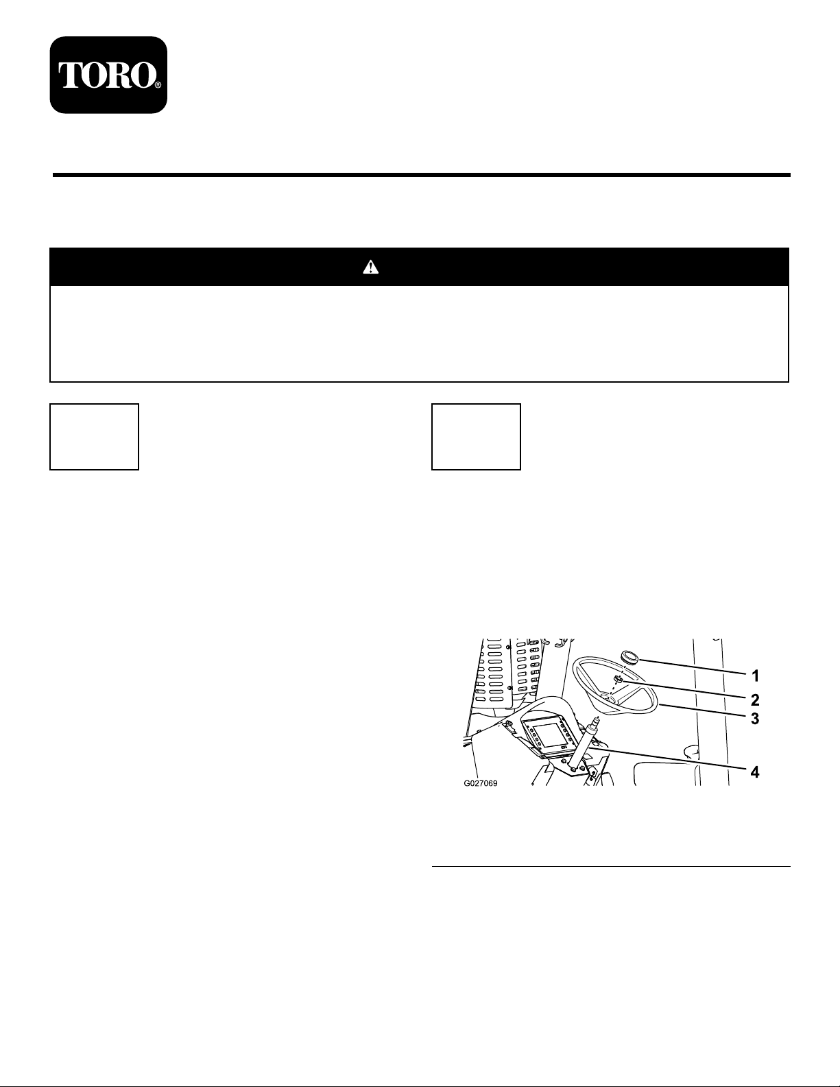
1.Prythecoveroutfromthehubofthesteeringwheel
(Figure1).
Figure1
1.Cover3.Steeringwheel
2.Nut(13/16inch)
4.Fixed-steeringcolumn
©2015—TheToro®Company
8111LyndaleAvenueSouth
Bloomington,MN55420
Registeratwww.T oro.com.
2.Removethenut(13/16inch)thatsecuresthesteering
wheeltothexed-steeringcolumn(Figure1).
3.Removethesteeringwheelbypullingitawayfromthe
column(Figure1).
OriginalInstructions(EN)
PrintedintheUSA
AllRightsReserved
*3398-100*A
Page 2
3
RemovingtheFixed-Steering
Column
NoPartsRequired
Procedure
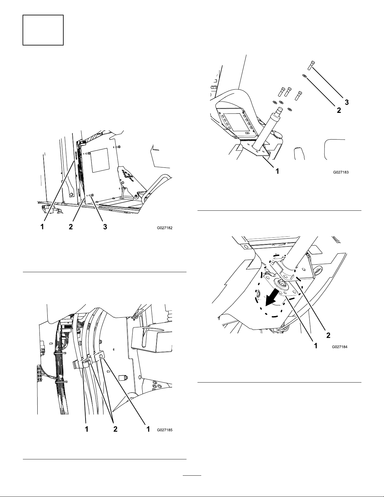
1.Removethe4hex-angedbolts(5/16x1inch)that
securethekickpaneltotheconsole(Figure2).
3.Removethe4bolts(3/8x1-1/2inch)and4washers
(3/8inch)thatsecurethexed-steeringcolumnand
thesteeringvalvetothesteeringsupport(Figure4).
Note:Donotdiscardthewashers.
Figure4
1.Steeringsupport3.Bolt(3/8x1-1/2inch)
2.Washer(3/8inch)
Figure2
1.Clipnut(console)3.Hex-angedbolts(5/16x
1inch)
2.Kickpanel
2.Loosenthe2bolts(5/16x1-3/4inch)and4clamp
blocksthatsecurethesteering-valvehosestothe
console(Figure3).
4.Separatethemountingangeofthexed-steering
columnfromthesteeringvalve(Figure5).
Figure5
1.Steeringvalve2.Mountingange(xed
steeringcolumn)
5.Movethesteeringvalveforwardandtothesideto
provideclearanceforremovingthexed-steering
column.
Figure3
1.Clampblocks2.Bolts(5/16x1-3/4inch)
6.Movethexed-steeringcolumndownandout
fromunderthesteeringsupportandremovethe
xed-steeringcolumnfromthemachine(Figure6).
2
Page 3

Figure7
1.Steeringsupport
4
InstallingtheTilt-Steering Column
Partsneededforthisprocedure:
4
Bolts(3/8-16x1-1/4inch)
InstallingtheColumn
Figure6
2.Fixed-steeringcolumn
1.Hole(steeringsupport)3.Splinesocket(steering
valve)
2.Threadedhole(steering
valve)
2.Alignthetilt-steeringcolumntothesteeringvalvewith
theshort-splineshaftdownandthewordPUSHthatis
embossedinthebootofthecolumnrearward(Figure
8).
Note:Haveanotherpersonhelpyouinstallthetiltsteering
column.
1.Pushthesteeringvalveupandalignthethreadedholes
inthesteeringvalvewiththeholesinthesteering
support(Figure7).
Note:Ensurethatthetopofthesteeringvalveisush
withthebottomofthesteeringsupport.
Figure8
1.Steering-wheelshaft3.PUSH(embossedinthe
boot)
2.Boot
3.Aligntheshort-splineshaft(attheangeendofthe
tilt-steeringcolumn)tothesplinesocketofthesteering
valvebyturningthesteering-wheelshaftofthecolumn
andinserttheshort-splineshaft(Figure9).
Note:Ensurethatthemountingangeofthe
tilt-steeringcolumnisushtothetopofthesteering
support.
3
Page 4

Figure9
5
InstallingtheSteeringWheel
NoPartsRequired
Procedure
1.Applymedium-grade,thread-lockingcompoundtothe
threadsofthesteering-wheelshaft.
2.Alignthespokesofthesteeringwheel(Figure10).
1.Splinesocket(steering
valve)
2.Hole(steeringsupport)5.Washer(3/8inch)
3.Hole(mounting
ange—tilt-steering
column)
4.Aligntheholesinthemountingangeofthe
tilt-steeringcolumn,theholesinthesteeringsupport,
andthethreadedholesinthesteeringvalve(Figure9).
5.Applymedium-grade,thread-lockingcompoundtothe
4bolts(3/8-16x1-1/4inch).
6.Assemblethecolumn,plate,andvalvewiththe4bolts
(3/8-16x1-1/4inch)includedinthiskitandthe4
washers(3/8inch),thatwereremovedinstep3of
3RemovingtheFixed-SteeringColumn(page1),as
showninFigure9.
7.Torquetheboltsto37to45N-m(27to33ft-lb).
8.Torquetheclampblockbolts,thatyouloosenedinstep
2of(page),to1978to2542N-cm(175to225in-lb).
4.Tilt-steeringcolumn
6.Bolt(3/8-16x1-1/4inch)
InstallingtheConsolePanel
Figure10
1.Steering-wheelshaft3.Nut(13/16inch)
2.Steeringwheel4.Cover
3.Alignthesplinesofthesteeringwheeltothesplines
ofthesteering-wheelshaftofthetiltsteeringcolumn
(Figure10).
4.Seatthesteeringwheelontothetiltsteeringcolumn
(Figure10).
5.Securethewheeltothecolumn(Figure10)withthe
nut(13/16inch)andtorquethenutto41to49N-m
(30to36ft-lb).
6.Rotatethebattery-disconnectswitchtotheON
position;refertotheOperator’ sManual.
7.Installtherightpanel;refertotheOperator’ sManual.
1.Applymedium-grade,thread-lockingcompoundtothe
4hex-angedbolts(5/16x1inch)thatyouremoved
instep1of(page).
2.Aligntheholesinthekickpanelwiththeclipnutsat
theconsole(Figure2).
3.Assemblethepaneltotheconsolewiththe4
hex-angedbolts(Figure2).
4.Torquetheanged-headboltsto1978to2542N-cm
(175to225in-lb).
4
Page 5

Operation
AdjustingtheTiltSteering Column
1.Stopthemachineandsettheparkingbrake.
2.Holdthesteeringwheelwith1hand.
3.Pressthelatchmechanism(locatedundertheword
PUSHthatisembossedinthebootofthesteering
column)untilthecolumnunlocks(Figure11).
Figure11
1.Latchmechanism—PUSH(embossedintheboot)
4.Movethesteeringwheeltothedesiredposition.
5.Releasethelatchmechanismandensurethatthe
steeringcolumnislockedinposition(Figure11).
5
Page 6

Notes:
6
Page 7

Notes:
7
Page 8

 Loading...