

Page 1

FormNo.3394-817RevA
TrencherMountKitforTrackedMachine
RT1200Trencher
ModelNo.25469
ModelNo.25469E
InstallationInstructions
WARNING
CALIFORNIA
Proposition65Warning
ThisproductcontainsachemicalorchemicalsknowntotheStateofCaliforniato
causecancer,birthdefects,orreproductiveharm.
Safety
Improperlyusingormaintainingthisattachmentcanresultininjury.Toreducethepotentialforinjury,comply
withthesesafetyinstructionsandthoseinthetractionunit
alertsymbol,whichmeansCaution,W arning,orDanger—personalsafetyinstruction.Failuretocomplywith
theinstructionmayresultinpersonalinjuryordeath.
Operator’ s Man ual
.Alwayspayattentiontothesafety
WARNING
Whentheengineisoff,attachmentsintheraisedpositioncangraduallylower.Someonebelowthe
attachmentmaybepinnedorinjuredbytheattachmentasitlowers.
Alwayslowertheattachmenteachtimeyoushutoffthetractionunit.
WARNING
Hydraulicuidescapingunderpressurecanpenetrateskinandcauseinjury.
•Makesureallhydraulicuidhosesandlinesareingoodconditionandallhydraulicconnectionsand
ttingsaretightbeforeapplyingpressuretothehydraulicsystem.
•Keepyourbodyandhandsawayfrompinholeleaksornozzlesthatejecthighpressurehydraulicuid.
•Usecardboardorpapertondhydraulicleaks.
•Safelyrelieveallpressureinthehydraulicsystembeforeperforminganyworkonthehydraulicsystem.
•Seekimmediatemedicalattentionifuidisinjectedintoskin.
CAUTION
Hydraulicttings,hydrauliclines/valves,andhydraulicuidmaybehotandcanburnyouifyoutouch
them.
•Weargloveswhenmaintaininghydrauliccomponents.
•Allowthetractionunitandtrenchertocoolbeforetouchinghydrauliccomponents.
•Donottouchhydraulicuidspills.
©2015—TheToro®Company
8111LyndaleAvenueSouth
Bloomington,MN55420
Registeratwww.T oro.com.
OriginalInstructions(EN)
PrintedintheUSA
AllRightsReserved
*3394-817*A
Page 2

Installation
LooseParts
Usethechartbelowtoverifythatallpartshavebeenshipped.
ProcedureDescription
1
2
3
4
5
6
7
Nopartsrequired
Nopartsrequired
Spacer
Bolts(1x2-1/2inch)
Locknut(1inch)
Washer(1inch)
Bolt(1x13inch)
Nopartsrequired
Nopartsrequired
45°elbowtting(3/8inch)
Pressurehose(2.5x10⁴cmor1x41
inch)
Case-drainhose(1.3x116cmor1/2
x45-3/4inch)
Returnhose(2.5x117cmor1x46
inch)
Cabletie
Qty.
Use
–
–
1
2
4
1
4
–
–
2
1
1
1
1
Preparetoinstallthetrencher.
Installthespeed-shiftswitch.
Installthespacertothetrencher
attachment.
Installthespeed-shiftswitch.
Preparethehydraulicmotor.
Connecttheliftcylinderhoses.
Installthehydraulichoses.
8
Nopartsrequired
1
PreparingtoInstallthe Trencher
NoPartsRequired
Procedure
1.Movethemachinetoalevelsurfacethatisbelowthe
liftingequipment.
2.Ifthebackhoeisinstalledonthemachine,lowerthe
boomuntilthebucketisontheground.
3.Ensurethatthetiltfeatureofthemachineisleveland
thetilt-lockoutpinissecuretothechassis-lockout
bracket;refertotheOperator’sManualforthemachine.
4.Shutoffthemachine,settheparkingbrake,and
removethekeyfromthekeyswitch.
–
Finishthetrencherinstallation.
2
InstallingtheSpeed-shift Switch
NoPartsRequired
Procedure
Installthespeed-shiftswitchasinstructedinoperator’ smanual
fortheCenterTrencher,RT1200TractionUnit.
2
Page 3
3
InstallingtheSpacertothe
TrencherAttachment
Partsneededforthisprocedure:
1
Spacer
2
Bolts(1x2-1/2inch)
4
Locknut(1inch)
1
Washer(1inch)
4
Bolt(1x13inch)
AssemblingtheSpacertotheTrencher
Attachment
Trencherattachmentweight:227kg(500lb)
Spacerweight:137kg(302lb)
Note:ThisprocedurereplacesInstallingtheTrencher
AttachmentintheSetUpsectionoftheCenterline
Trencher
1.RaisetheattachmentofftheoorasshowninFigure1.
operator’ s man ual
Important:Ensurethattheliftingequipmenthas
aliftingcapacityofatleast227kg(500lb).
.
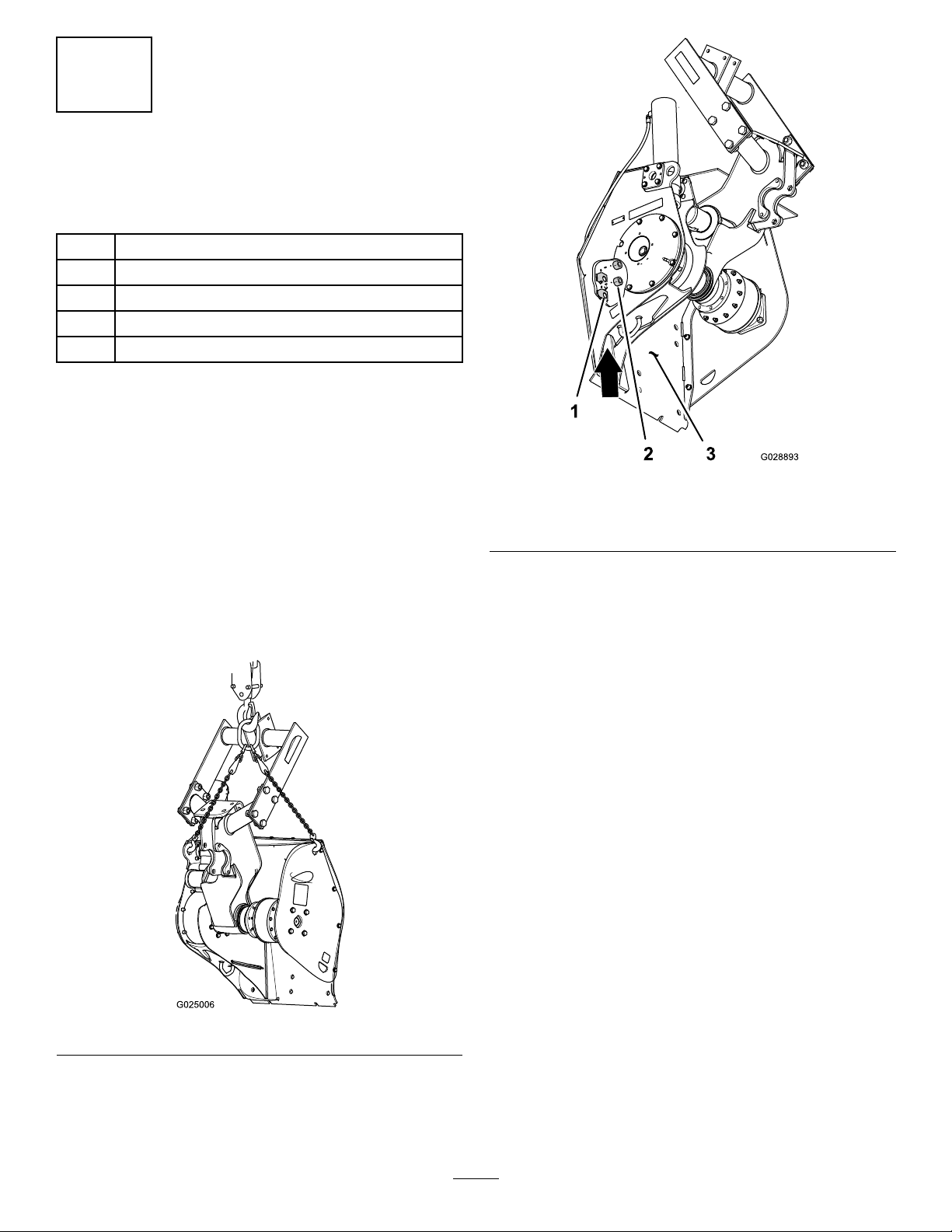
Figure2
1.Nutretainer3.Trencherbackplate
2.Locknut(1inch)
3.Usingliftingequipment,liftthespacerwiththe2hole
rowsofthespacerup(Figure3).
Figure1
2.Insertalocknut(1inch)intotheupperandlowernut
retainerlocatedinsidethetrencherattheleftholesin
rows1and2ofthetrencherbackplate(Figure2).
3
Page 4

Figure3
1.Bolt(1x2-1/2inch)4.Row1hole(spacer)
2.Washer(1inch)5.Row2hole(trencher—left
atcagenut)
3.Locknut(1inch)
4.Aligntherow1holesinthespacerwiththerow1holes
inthetrencherasshowninFigure3.
5.Assembleabolt(1x2-1/2inch)throughthelefttop
holeinthespacerandleftrow1holeinthetrencher
andthreadtheboltintotherow1locknut(Figure3)
thatyouinstalledinstep2.
6.Assembleabolt(1x2-1/2inch)throughtherighttop
holeinthespacerandrightrow1holeinthetrencher
andsecurethebolt,spacer,andtrencher(Figure3and
Figure4)withawasher(1inch)andlocknut(1inch).
Figure4
1.Spacer4.Washer(1inch)
2.Trencherbackplate
3.Bolt(1x2-1/2inch)
5.Locknut(1inch)
7.Torquetheboltsandthelocknutsto1341to1368N-m
(989to1009ft-lb).
AssemblingtheSpacerandTrencher
AttachmenttotheMachine
Note:ThisprocedurereplacesInstallingtheTrencher
AttachmentintheSetUpsectionoftheCenterline
Trencher
1.Insertthe2bolts(1x13inch)throughintothegusset
operator’ s man ual
.
plateopeningsheadoftheboltrst(Figure5).
Figure5
1.Row2holes(mounting
plate—machine)
2.Gussetplateopening4.Bolt(1x13
3.Bolt(1x13inch)–inserted
headrst
inch)—installedposition
2.Install2bolts(1x13inch)throughtherow2holesin
themountingplateofthemachine(Figure5).
4
Page 5

3.Aligntherow2holesinspacerwiththe2bolts(1x13
inch)thatyouinstalledinstep1(Figure6).
Figure6
1.Mountingplate(machine)3.Row2holes(spacer)
2.Bolt(1x13inch)
1.Lowerlocknutandretainer
2.Bolts(1x13inch)
Figure8
3.Row3holes(trencher
backplate)
4.Slidethespacerandtrencherontotheboltsuntilthe
faceofthespacerisushtothemountingplateofthe
machine(Figure6)
5.Attherightsideofthetrencherbackplate,assemblea
washer(1inch)andlocknut(1inch)ontothebolt(1x
13inch)asshowninFigure7.
Figure7
1.Trencherbackplate
2.Bolt(1x13inch)–right4.Locknut(1inch)
3.Washer(1inch)
7.Install2bolts(1x13inch)throughtherow3holesin
thetrencherbackplate,therow2holesinthespacer,
andthebottomholesinthemountingplateofthe
machine(Figure8).
8.Atthebottomfrontofthemountingplateofthe
machine(Figure9),thread2locknuts(1inch)ontothe
bolts(1x13inch).
Figure9
1.Up
2.Backofthemachine5.Mountingplate(machine)
3.Locknuts(1inch)6.Spacer
4.Bolts(1x13inch)
6.Attheleftsideofthetrencherbackplate,threadthe
bolt(1x13inch)throughtherow2locknutinthe
trencher(Figure8)thatyouinstalledinstep2of3
InstallingtheSpacertotheTrencherAttachment(page
2).
9.Torquetheboltsandthelocknutsto1341to1368N-m
(989to1009ft-lb).
10.Removetheliftingequipmentfromthespacerand
trencherattachment.
5
Page 6

4
InstallingtheSpeed-shift
Switch
NoPartsRequired
Procedure
Installthespeed-shiftswitchasinstructedinoperator’ smanual
fortheCenterTrencher,RT1200TractionUnit.
5
PreparingtheHydraulicMotor
NoPartsRequired
Procedure
Preparethehydraulicmotorasinstructedinoperator’smanual
fortheCenterTrencher,RT1200TractionUnit.
Figure10
1.Liftcylinder5.45°elbowtting(3/8inch)
2.Cap(3/8inch)
3.Bulkheadtting(extend
circuit)
4.Bulkheadtting(retract
circuit)
2.Installthe2elbowttings(45°)ontothebulkhead
ttingsngertight(Figure10).
3.Connecttheextendhosetothe45°elbowtting
connectedtothebulkheadttingfortheextend
hydrauliccircuit(Figure10).
6.Extendhose
7.Retracthose
6
ConnectingtheLiftCylinder Hoses
Partsneededforthisprocedure:
2
45°elbowtting(3/8inch)
Procedure
Note:ThisprocedurereplacesConnectingtheLift
CylinderHosesintheSetUpsectionoftheCenterline
Trencher
1.Removethe2caps(3/8inch)fromthebulkhead
operator’ s man ual
ttingsfortheextendandretractcircuitsforthelift
cylinder(Figure10).
.
4.Connecttheretracthosetothe45°elbowtting
connectedtothebulkheadttingfortheretract
hydrauliccircuit(Figure10).
5.Tightentheelbowstothebulkheadttingsandthe
hosetotheelbowsto20to28N-m(15to21lb-ft).
7
InstallingtheHydraulicHoses
Partsneededforthisprocedure:
1
Pressurehose(2.5x10⁴cmor1x41inch)
1
Case-drainhose(1.3x116cmor1/2x45-3/4inch)
1
Returnhose(2.5x117cmor1x46inch)
1
Cabletie
Procedure
Note:ThisprocedurereplacesInstallingtheHydraulic
HosesintheSetUpsectionoftheCenterlineTrencher
operator’ s man ual
6
.
Page 7

1.Removethe2caps(1inch)andthe1cap(5/8inch)
fromthebulkheadttingsinthehydraulic-attachment
panel(Figure11).
Figure12
Figure11
1.Bulkheadtting
(pressure-hydrauliccircuit)
2.Bulkheadtting(case
drain)
3.Bulkheadtting
(return-hydrauliccircuit)
4.Hydraulic-attachment
panel
5.Caps
2.Installthepressurehose(2.5x10⁴cmor1x41inch);
case-drainhose(1.3x116cmor1/2x45-3/4inch);
andreturnhose(2.5x117cmor1x46inch)between
thettingsonthehydraulic-attachmentpanel(Figure
12)andthettingsthatyouinstalledonthehydraulic
motorasshowninFigure13.
Note:Ensurethattheangledttingonthepressure
hoseisconnectedtothebulkheadttingforthe
pressure-hydrauliccircuit.Alsoensurethattheangled
ttingonthereturnhoseisconnectedtothebulkhead
ttingforthereturn-hydrauliccircuitatthehydraulic
attachmentpanel.
1.Bulkheadtting
(pressure-hydraulic
circuit—A)
2.Bulkheadtting(case
drain)
3.Bulkheadtting
(return-hydraulic
circuit—B)
4.Pressurehose(2.5x10⁴
cmor1x41inch)
Figure13
1.45°elbowtting(3/4inch,
casedrain)
2.90°anged-elbowtting(
pressure-hydrauliccircuit)
3.90°anged-elbowtting
(return-hydrauliccircuit)
5.Case-drainhose(1.3x
116cmor1/2x45-3/4
inch)
6.Returnhose(2.5x117cm
or1x46inch)
7.Cabletie
4.Pressurehose(2.5x10⁴
cmor1x41inch)
5.Case-drainhose(1.3x
116cmor1/2x45-3/4
inch)
6.Returnhose(2.5x117cm
or1x46inch)
3.Securethe3hydraulichoseswithacabletie(Figure12).
4.Torquethehydraulicttingsandhoses;refertothe
ttingtorquetablebelow:
7
Page 8

FittingTorqueTable
ComponentTorquevalue(N-m)Torquevalue(lb-ft)
8hex-headbolts(12x45mm)
Jamnutforthe45°elbowtting
(3/4inch)
Case-drainhose(1.3x1 16cm
or1/2x45-3/4inch)
Pressurehose(2.5x104cm
or1x41inch)andreturnhose
(2.5x117cmor1x46inch)
80to10059to73Figure14
142to175105to129Figure14
58to7243to53Figure13andFigure14
122to14990to110Figure13andFigure14
FinishingtheTrencher Installation
NoPartsRequired
Procedure
8
1.Swivelnut(casedrain
hose)
2.Swivelnuts(pressure
hoseandreturnhose)
Figure14
3.Jamnut
4.8hex-headbolt(12x45
mm)
Performthefollowingproceduresasinstructedinoperator’s
manualfortheCenterTrencher,RT1200TractionUnit:
•ConnectingtheWiringHarnesstotheHydraulicMotor
•PurgingAirfromtheHydraulicMotorandLiftCylinder
•InstallingtheSprocket
•InstallingtheAuger
•InstallingtheBoom
•AligningtheBoom
•InstallingtheDiggingChain
•InstallingtheRestraintBar
8
 Loading...