

Page 1
FormNo.3378-127RevA
1
2
g024982
BlockHeaterKit
RT1200Trencher
ModelNo.25468
ModelNo.25468E
InstallationInstructions
Installation
WARNING
CALIFORNIA
Proposition65Warning
ThisproductcontainsachemicalorchemicalsknowntotheStateofCaliforniato
causecancer,birthdefects,orreproductiveharm.
2.Allowtheengineandcoolingsystemtocool.
3.Removetheleftandrightsidepanels;refertoOperator’ s
1
Manualforthemachine.
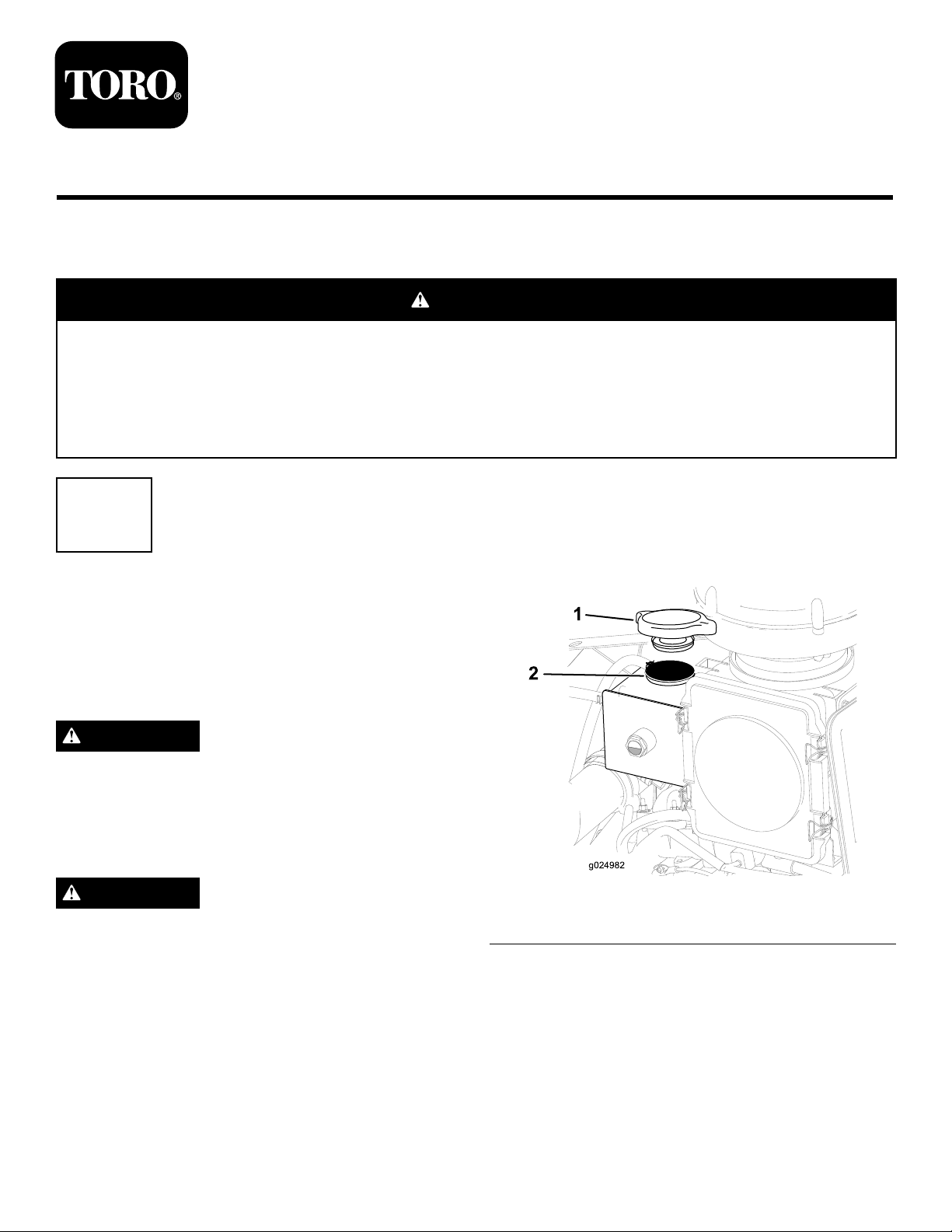
4.Removetherecovery-tankcapfromthetank(Figure1).
PreparingtoInstalltheBlock Heater
NoPartsRequired
DrainingtheCoolant
WARNING
Coolantistoxic.
•Keepcoolantawayfromchildrenandpets.
•Ifnotreused,disposeofcoolantinaccordance
withlocalgovernmentregulations.
WARNING
Heatedcoolantsprayorsteamcancausepersonal
injury.
•Donotremovetherecoverytankcapwhenthe
engineishot.
•Waituntilthecoolanttemperatureisbelow50°C
(120°F)beforeremovingtherecoverytankcap.
1.Recovery-tankcap2.Fillerneck
5.Placeadrainpanwithaminimumcapacityof23L
(6USgallons)undertheopenendofthedrainhose
(Figure3).
Figure1
Important:Donotpourcoolantontothegroundorinto
anunapprovedcontainerthatcanleak.
1.Movethemachinetoalevelsurface,shutoffthe
engine,andremovethekeyfromthekeyswitch.
©2014—TheToro®Company
8111LyndaleAvenueSouth
Bloomington,MN55420
Registeratwww.T oro.com.
OriginalInstructions(EN)
PrintedintheUSA
AllRightsReserved
*3378-127*A
Page 2
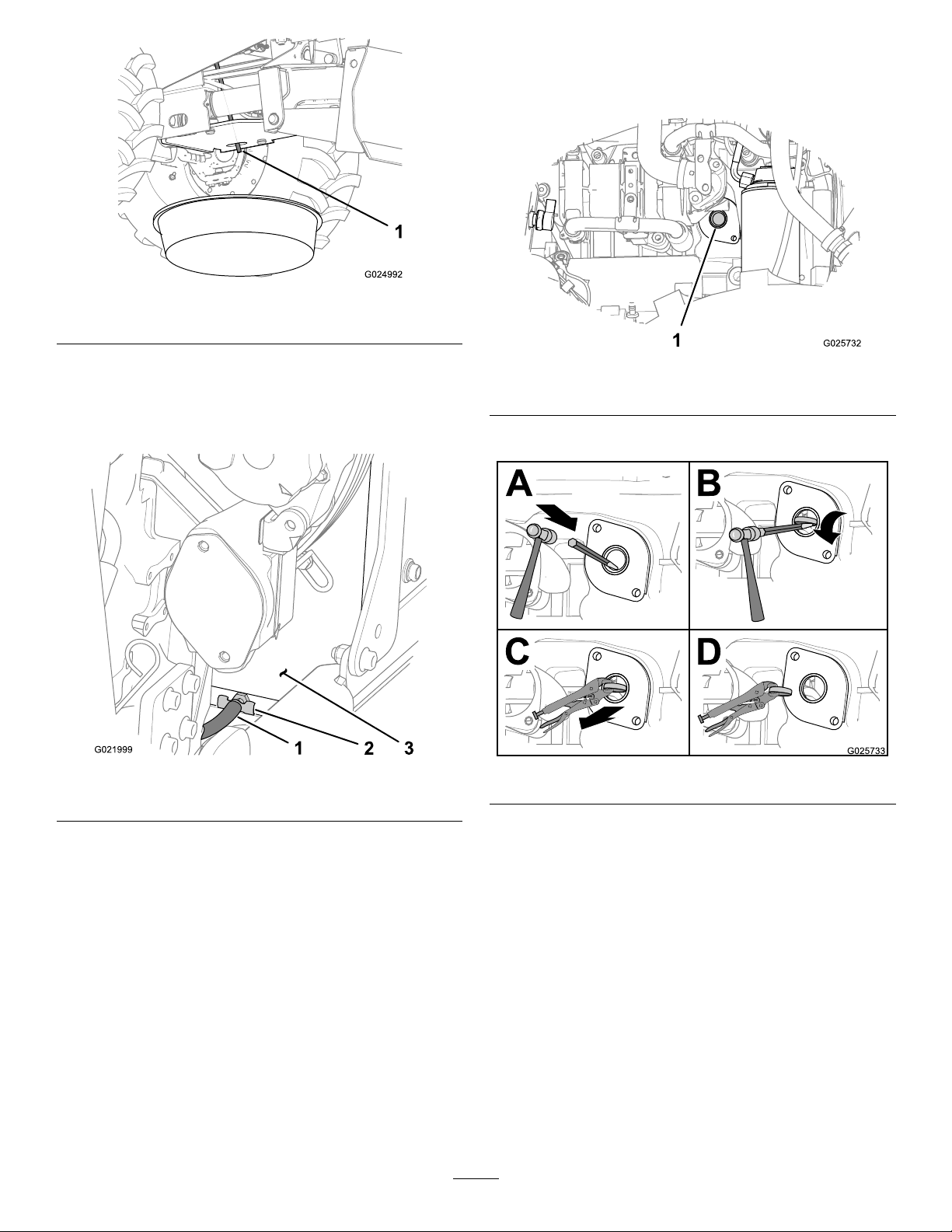
1.Drainhose
RemovingtheFreezePlug
1.Locatetheforwardfreezeplugattherightsideofthe
engine.
Figure2
6.Openthedrainvalveontheradiatorandallowthe
coolanttodraincompletely.
Note:Disposeoftheusedcoolantproperlyaccording
tolocalcodes.
Figure3
1.Drainvalve
Figure4
1.Freezeplug(rightsideofengine)
2.Removethefreezeplug.
Figure5
7.Closethedrainvalve(Figure3).
3.Thoroughlycleantheholeintheengineblockwitha
rag.
Note:Ensurethattherearenoburrs,metalshavings,
orsharpedgesthatcancuttheO-ring.
2
Page 3
2
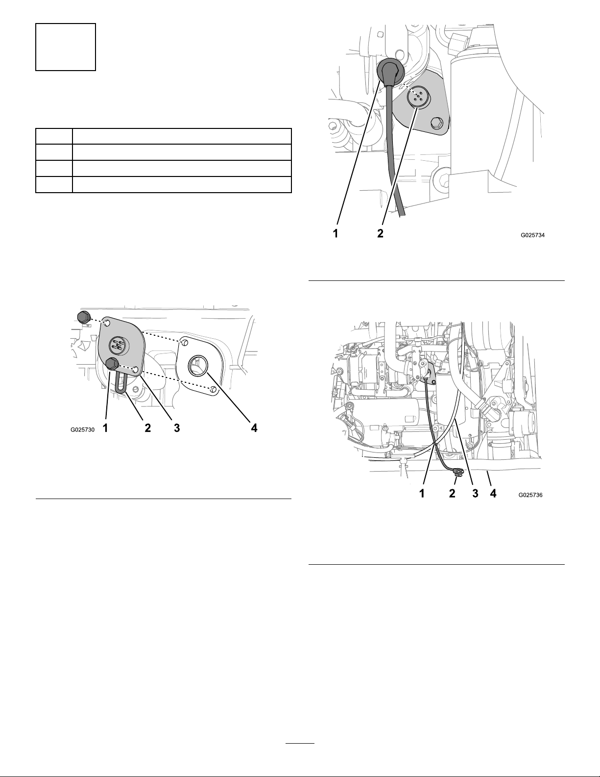
InstallingtheBlockHeaterKit
Partsneededforthisprocedure:
1Blockheater
2
Flanged-headbolts(8x16mm)
1Heater-electricalcord
1
Cabletie
Procedure
1.LubricatetheO-ringontheblockheaterwith15W -40
engineoil.
2.Inserttheblockheaterintotheholeintheengineblock
withtheelementoftheheaterpointingdown(Figure
6).
Figure6
1.Flanged-headbolts(8x
16mm)
2.Heaterelement
3.Aligntheholeintheblockheaterwiththeholeinthe
engineblock(Figure6).
4.Securetheblockheatertotheblock(Figure6)withthe
2anged-headbolts(8x16mm).
3.Blockheater
4.Hole(engineblock)
Figure7
1.Connector(electricalcord)2.Connector(blockheater)
7.Routethecordoverthetopoftheright-framechannel
ofthemachine(Figure8).
Figure8
1.Cabletie3.Chargecable(alternator)
2.Plug(electricalcordforthe
blockheater)
4.Right-framechannel
5.Torquetheboltsto24N-m(212in-lb).
6.Connecttheconnectoroftheheater-electricalcordto
theconnectoroftheblockheater(Figure7).
8.Securetheelectricalcordoftheblockheatertothe
chargecableofthealternatorwithacabletie(
3
Figure8)
Page 4

3
FillingtheCoolingSystem
Note:Ifthecoolantlevelislow ,addcoolanttothe
recoverytankuntiltheuidlevelisuptothemidpoint
ofthesightgauge.
7.Installthesidepanels;refertoOperator’ sManualforthe
machine.
withAntifreeze
NoPartsRequired
Procedure
Thecoolantcapacityoftheengineandtheradiator:18.5
L(19.5USqt).
Important:Fillthecoolingsystemproperlytoprevent
airlocksinthecoolingpassages.Failingtoventthe
coolingsystemproperlycandamageboththeengine
andthecoolingsystem.
Important:Neverusesealingadditivetostopleaks
inthecoolingsystem.Thiscanresultinthecooling
systempluggingandinadequatecoolantow,causing
theenginetooverheat.
1.Removetheradiatorcapfromtherecoverytank
(Figure1).
2.Fillthecoolingsystemwiththespeciedcoolant
mixture(Figure9)untiltheuidlevelisuptothe
midpointinthesightgauge(Figure9).
Operation
UsingtheBlockHeater
ConnectingtheBlockHeaterto
ElectricalPower
Electricalsourcespecication:110to120voltsAC
Note:Toreducetheriskofelectricshock,thisappliance
hasapolarizedplug(i.e.,uniquebladeshapesandwidths).
UseonlyapolarizedsocketthatiscompliantwithNEMA
specicationsattheelectricalsource,andpolarizedextension
cordsthatareUL-listed(CSAcertiedinCanada)for
outdooruse.Apolarizedplugoftheelectricalcordforthe
blockheaterwilltinapolarizedcordonlyoneway .If
youdonothaveanoutletthatisgroundedandpolarized,
contactaqualiedelectriciantoinstalltheproperoutlet.Do
notmodifytheelectricalcordfortheblockheaterorthe
extensioncordpluginanyway .
1.Beforeparkingthemachine,moveitclosetotheoutlet
thatwillserveastheelectricalsourcefortheblock
heater.
Figure9
1.Coolantlevel(midpointin
thesightgauge)
2.Funnel
3.Installtherecovery-tankcap(Figure1).
4.Starttheengineandrunitathalfthrottlefor5minutes.
5.Stoptheengineandremovethekey.
3.Coolant(amixtureof50%
ethyleneglycoland50%
water)
2.Settheparkingbrake,shutofftheengine,andremove
thekeyfromthekeyswitch.
3.Iftheelectricalcordfortheblockheaterisinsidethe
enginecompartment,removetherightsidepanel;refer
totheOperator’sManualforthemachine.
4.Plugtheelectricalcordfortheblockheaterintoa
grounded-typeextensioncord(Figure10).
Important:Useonly3-wireextensioncordswith
terminalsandsocketsforthelive,neutral,and
groundcircuits.
Usetheshortestextensioncordpossibleandin
1piece.
Note:Whenusinganin-linegroundfaultcircuit
interrupter(GFCI)device,locatetheGFCIascloseto
theelectricalsourceaspossible.
6.Wait30minutes,thenchecktheuidlevelinthe
recoverytank.
4
Page 5

DisconnectingtheBlockHeaterfrom
ElectricalPower
1.Disconnecttheextensioncordfromtheoutletthatis
servingastheelectricalsourcefortheblockheater
(Figure10).
2.Removetherightsidepanel;refertotheOperator’s
Manualforthemachine.
3.Disconnectthecordoftheblockheatercordintothe
extensioncord(Figure10).
4.Stowthecordoftheblockheaterintheengine
compartment,awayfrommovingparts.
Figure10
1.Electricalcord(block
heater)
2.Extensioncord
3.Driploop
4.In-lineGFCI
5.Grounded-electricaloutlet
5.Stowtheconnectorsoftheblock-heatercordand
extensioncordinsidetheenginecompartmentofthe
machine.
6.Routetheextensioncordtoformadriploopbelow
theconnectionattheblock-heatercordandextension
cord,andtheconnectionattheextensioncordandthe
receptaclefortheelectricalsource(Figure10).
7.Connectagroundedextensioncordintothe
grounded-electricaloutletthatwillserveasthe
electricalsourcefortheblockheater(Figure10).
Important:Connecttheblockheatertoa3-pole
receptaclewithlive,neutral,andgroundcircuits
only.
8.Installtherightsidepanel;refertotheOperator’sManual
forthemachine.
5.Installtherightsidepanel;refertotheOperator’sManual
forthemachine.
5
Page 6

Notes:
6
Page 7

Notes:
7
Page 8

 Loading...