

Toro 25467, 25467E Installation Instructions
AuxiliaryControlKit
762BackhoeforRT1200Trencher
ModelNo.25467
ModelNo.25467E
ThisproductcontainsachemicalorchemicalsknowntotheStateofCaliforniato
causecancer,birthdefects,orreproductiveharm.
LooseParts
Usethechartbelowtoverifythatallpartshavebeenshipped.
FormNo.3378-123RevA
InstallationInstructions
WARNING
CALIFORNIA
Proposition65Warning
Description
Nopartsrequired
Startbutton
Rockerswitch3
Nopartsrequired
Nopartsrequired
RemovingtheConsolePanel
1.Parkthemachineonalevelsurfaceandlowerthe
backhoetotheground.
2.Shutofftheengine,andremovethekeyfromthekey
switch.
3.RotatethebatterydisconnectswitchtotheOff
position;refertotheOperator’ sManualforthemachine.
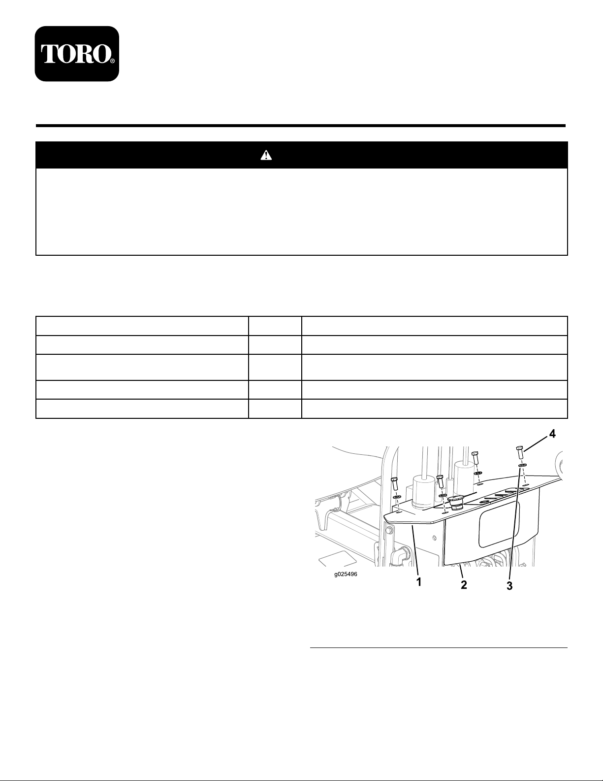
4.Removethe4hex-headbolts(3/8x1inch)and4
washers(3/8inch)thatsecuretheconsolepaneltothe
operatorconsoleforthebackhoe(Figure1).
Qty.
Use
–
1
–
–
Removetheconsolepanel.
Installthestartbuttonandrockerswitches.
Connectthebackhoewiringtothebuttonandswitches.
Installtheconsolepanel.
Figure1
©2014—TheToro®Company
8111LyndaleAvenueSouth
Bloomington,MN55420
Registeratwww.T oro.com.
1.Consolepanel3.Washer(3/8inch)
2.Operatorconsole4.Bolt(3/8x1inch)
5.Removethe3rectangularplugsfromtheconsolepanel
(Figure2).
Note:Discardthe3plugsafterremoval.
OriginalInstructions(EN)
PrintedintheUSA
AllRightsReserved
*3378-123*A
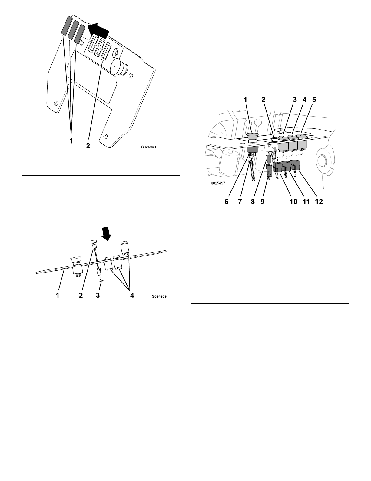
Figure2
ConnectingtheBackhoe
WiringtotheButtonsand
Switches
1.Connectthe10-socketconnectorofthebackhoe
wiringharnessthatislabeledThrottletothe10-pin
connectoroftheinboardrockerswitch(Figure4).
Note:Thisistherockerswitchthatisclosesttothe
startbutton.
1.Rectangularplugs
2.Consolepanel
InstallingtheStartButtonand
RockerSwitches
1.Removethejamnutfromthestartbutton(Figure3).
Figure3
1.Consolepanel
2.Startbutton
2.Inserttheelectricalconnector,wires,andcaseofthe
startbuttonthroughthe15.8mm(5/8inch)holein
theconsolepanel(Figure3).
3.Securethestartbuttontotheconsolepanelwiththe
jamnut(Figure3)thatyouremovedinstep1.
4.Alignthe3rockerswitchedtothe3rectangular
openingsintheconsolepanel,andsnapthemintothe
panel(
Figure3).
Note:Ensurethatthealignmentkeyfortheswitchis
pointingtotheforwardedgeofthepanel.
3.Jamnut
4.Rockerswitch
Figure4
1.E-stopbutton
2.Startbutton6.Screw
3.Inboardrocker
switch(throttle)
4.Centerrocker
switch(backll
blade)
5.Outboard
rockerswitch
(propel)
7.Forkedterminal11.10-socket
8.2-socket
connector(start
button)
9.2-pinconnector
(backhoe
wiringharness)
10.10-socket
connector
(throttle)
connector
(backllblade)
12.10-socket
connector
(propel)
2.Connectthe10-socketconnectorofthebackhoewiring
harnessthatislabeledBladetothe10-pinconnector
ofthecenterrockerswitch(Figure4).
3.Connectthe10-socketconnectorofthebackhoewiring
harnessthatislabeledPropeltothe10-pinconnector
oftheoutboardrockerswitch(Figure4).
4.Connectthe2-pinconnectorofthebackhoewiring
harnesstothe2-socketconnectorofthestartbutton
(
Figure4).
5.Afteralloftheconnectionsaremade,verifythatthe
seatswitchandtheE-stopfunctionproperlybefore
operatingthemachine.
2
 Loading...