

Page 1
FormNo.3389-756RevA
PlowKit
RT1200Trencher
ModelNo.25463—SerialNo.314000001andUp
ModelNo.25463E—SerialNo.314000001andUp
Registeratwww.T oro.com.
OriginalInstructions(EN)
*3389-756*A
Page 2
WARNING
CALIFORNIA
Proposition65Warning
Thisproductcontainsachemicalorchemicals
knowntotheStateofCaliforniatocausecancer,
birthdefects,orreproductiveharm.
Introduction
Thisvibratoryplowisanattachmentdesignedforuseon
Toroutilityequipmenttopullexiblepipeandcableintoand
throughsoil.Itisdesignedtobeusedbytrainedoperators
primarilyforroutingirrigationandutilitylinesunderground
withouthavingtodigatrenchforanundergroundtransectof
thepipeorcable.
Readthisinformationcarefullytolearnhowtooperateand
maintainyourproductproperlyandtoavoidinjuryand
productdamage.Youareresponsibleforoperatingthe
productproperlyandsafely.
Thismanualidentiespotentialhazardsandhassafety
messagesidentiedbythesafetyalertsymbol(Figure2),
whichsignalsahazardthatmaycauseseriousinjuryordeath
ifyoudonotfollowtherecommendedprecautions.
Figure2
1.Safetyalertsymbol
Thismanualuses2wordstohighlightinformation.
Importantcallsattentiontospecialmechanicalinformation
andNoteemphasizesgeneralinformationworthyofspecial
attention.
YoumaycontactTorodirectlyatwww.Toro.comforproduct
andaccessoryinformation,helpndingadealer,ortoregister
yourproduct.
Wheneveryouneedservice,genuineT oroparts,oradditional
information,contactanAuthorizedToroServiceDealer
orToroCustomerServiceandhavethemodelandserial
numbersofyourproductready.Figure1illustratesthe
locationofthemodelandserialnumbersontheproduct.
Writethenumbersinthespaceprovided.
Figure1
1.Locationofthemodelandserialnumberplate
ModelNo.
SerialNo.
©2014—TheToro®Company
8111LyndaleAvenueSouth
Bloomington,MN55420
Contactusatwww.Toro.com.
2
PrintedintheUSA
AllRightsReserved
Page 3

Contents
Safety
Safety...........................................................................3
SafetyandInstructionalDecals.................................5
Setup............................................................................6
1InstallingthePlowControlSwitches........................7
2PreparingtoInstalltheVibratoryPlow.....................8
3InstalltheCounterweighttotheTower
Assembly............................................................8
4PreparingtoInstalltheTowerandCounterweight
Assembly...........................................................10
5InstallingtheT owerandCounterweight
Assembly...........................................................11
6ConnectingtheLiftandSwingCylinder
Hoses................................................................15
7InstallingtheShakerBox.......................................19
8InstallingtheTiltandTrimCylinder
Hoses................................................................21
9InstallingtheHydraulicMotorHoses......................24
10BleedingtheAirfromtheTiltandTrim
CylindersandtheHydraulicMotor........................26
Operation....................................................................28
UsingtheTransportLock........................................28
UsingtheVibratoryPlow........................................29
TransportingtheTractionUnitwithaVibratory
Plow.................................................................39
Attachments/Accessories........................................39
OperatingTips......................................................40
Maintenance.................................................................41
RecommendedMaintenanceSchedule(s)......................41
GreasingtheFittings...............................................41
TorquingtheFastenersontheShakerBox..................42
Storage........................................................................43
Troubleshooting...........................................................44
Improperlyusingormaintainingthevibratoryplow
canresultininjury.Toreducethepotentialforinjury,
complywiththesesafetyinstructionsandthoseinthe
tractionunit
thesafetyalertsymbol,whichmeansCaution,Warning,
orDanger—personalsafetyinstruction.Failureto
complywiththeinstructionmayresultinpersonalinjury
ordeath.
Operator’ s Man ual
.Alwayspayattentionto
DANGER
Theremaybeburiedpower,gas,and/ortelephone
linesintheworkarea.Anelectricshockoran
explosionmayoccurifyouplowintoautilityline.
Havethepropertyorworkareamarkedforburied
linesanddonotplowinmarkedareas.Contactyour
localmarkingserviceorutilitycompanytohavethe
propertymarked(forexample,intheUnitedStates,
call811forthenationwidemarkingservice).
DANGER
Theplowbladeandothermovingpartsonthe
machinemaycutorseveryourhands,feet,orother
bodyparts.
•Keephands,feet,andanyotherpartofyour
bodyorclothingawayfromtheplowbladeand
othermovingparts.
•Beforeadjusting,cleaning,repairing,or
inspectingthevibratoryplow,lowertheplowto
theground,stoptheengine,waitforallmoving
partstostop,andremovethekey.
WARNING
Whentheengineisoff,attachmentsintheraised
positioncangraduallylower.Someonebelow
theattachmentmaybepinnedorinjuredbythe
attachmentasitlowers.
Alwayslowertheattachmenteachtimeyoushut
offthetractionunit.
3
Page 4

WARNING
Whengoingupordownhill,themachinecould
overturniftheheavyendistowardthedownhill
side.Someonemaybepinnedorseriouslyinjured
bythemachineifitoverturns.
Operatethemachineupanddownslopeswith
theheavyendofthemachineuphill.Anattached
vibratoryplowwillmakethebackendofthe
machineheavy.
WARNING
Lightningcancausesevereinjuryordeath.
Iflightningisseenorthunderisheardinthearea,
donotoperatethemachine;seekshelter.
CAUTION
Hydraulicuidescapingunderpressurecan
penetrateskinandcauseinjury.Fluidinjectedinto
theskinmustbesurgicallyremovedwithinafew
hoursbyadoctorfamiliarwiththisformofinjury;
otherwise,gangrenemayresult.
•Keepyourbodyandhandsawayfrompin-hole
leaksornozzlesthatejecthigh-pressure
hydraulicuid.
•Usecardboardorpapertondhydraulicleaks;
neveruseyourhands.
CAUTION
Hydraulicttings,hydrauliclines/valves,and
hydraulicuidmaybehotandcanburnyouifyou
touchthem.
•Weargloveswhenmaintaininghydraulic
components.
•Allowthetractionunitandvibratoryplowto
coolbeforetouchinghydrauliccomponents.
•Donottouchhydraulicuidspills.
4
Page 5
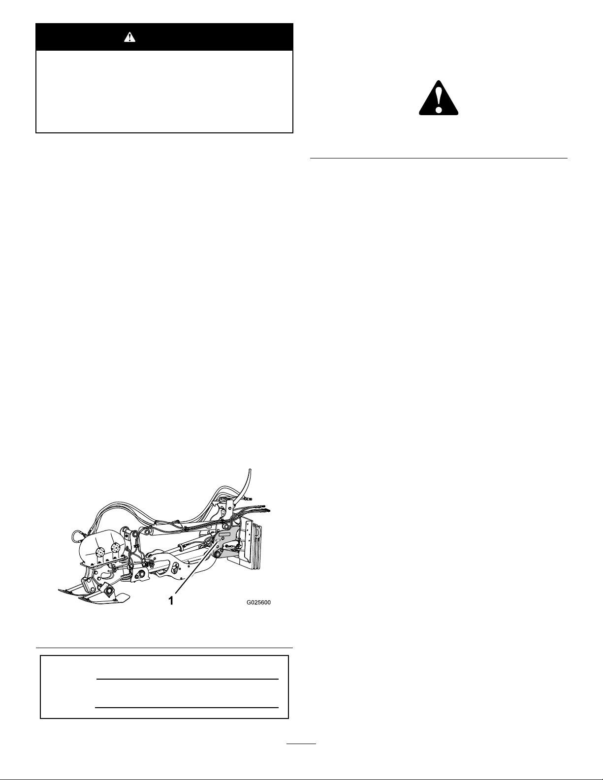
SafetyandInstructionalDecals
Safetydecalsandinstructionsareeasilyvisibletotheoperatorandarelocatednearanyareaofpotential
danger.Replaceanydecalthatisdamagedorlost.
1.Decal125-6671
125-6671
1.Explosionhazard;electricshockhazard—calllocalutilities
beforedigging.
125–6684
1.Cutting/dismembermenthazard,plow—keepbystanders
awayfromtheplow;stayawayfrommovingparts;keepall
guardsandsafetiesinplace.
Figure3
2.Decal125-6684(2)—bothsides
5
Page 6

Installation
LooseParts
Usethechartbelowtoverifythatallpartshavebeenshipped.
ProcedureDescription
1
2
3
4
5
6
7
8
Switch
Nopartsrequired
Towerassembly1
Counterweightassembly
Hex-headbolt(1x8-1/2inch)
Hex-headbolt(1x3-1/2inch)
Washer(1inch)
Locknut(1inch)
Locknut(1inch)
Hex-headbolts(1x8-1/2inch)
Washers(1inch)
Nuts(1inch)
Connectortting(3/8inch)
Nopartsrequired
Connectortting(3/8inch)
Squarenut(5/16inch)
Clampblock(2hose)
Coverplate
Washer(5/16inch)
Bolt(5/16x2-3/4inch)
Squarenut(3/8inch)
Clampblock(3hose)
Bolt(3/8x2-3/4inch)
Washer(3/8inch)
Bar1
Qty.
10
Use
3
–
1
2
2
6
6
2
4
8
6
4
–
4
3
3
3
3
2
2
2
2
Installtheplowoatswitches.
Preparetoinstallthevibratoryplow.
Installthecounterweighttothetower
assembly.
Preparetoinstallthetowerand
counterweightassembly .
Assemblethelower-centermounting
bolt(machineswithatrackdriveonly).
Connectthehydrauliccylinderhoses.
Installtheshakerbox.
Installthetiltandtrimcylinderhoses.
9
10
Important:Installafrontmountedaccessorysuchasthecounterweightandreelkitorthebackhoeontothetraction
unitbeforeinstallingthevibratoryplow.
Important:Installtheauxiliaryhydraulicskitontothetractionunitbeforeinstallingthevibratoryplow.
Nopartsrequired
Nopartsrequired
6
–
–
Installthehydraulicmotorhoses.
Bleedairfromthetiltandtrimcylinders
andthehydraulicmotor.
Page 7
1
InstallingthePlowControl Switches
Partsneededforthisprocedure:
3
Switch
Procedure
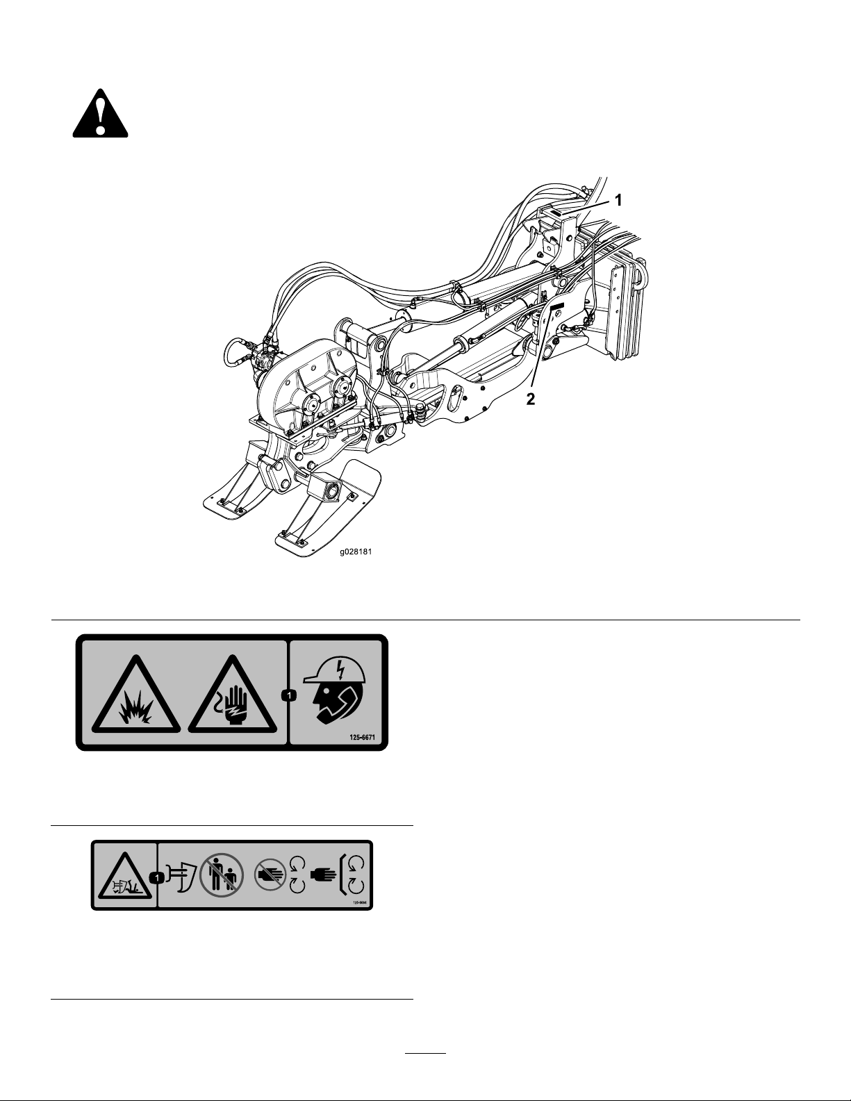
1.Removethe6hex-angedbolts(12x30mm)that
securetherear-coverplatetotherearbulkheadofthe
machine,andremovethecoverplate(Figure4).
Figure5
Figure4
1.Buklkhead
2.Rear-coverplate
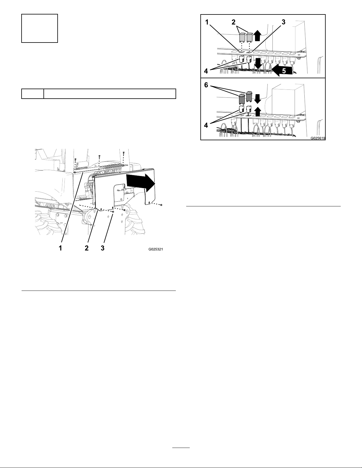
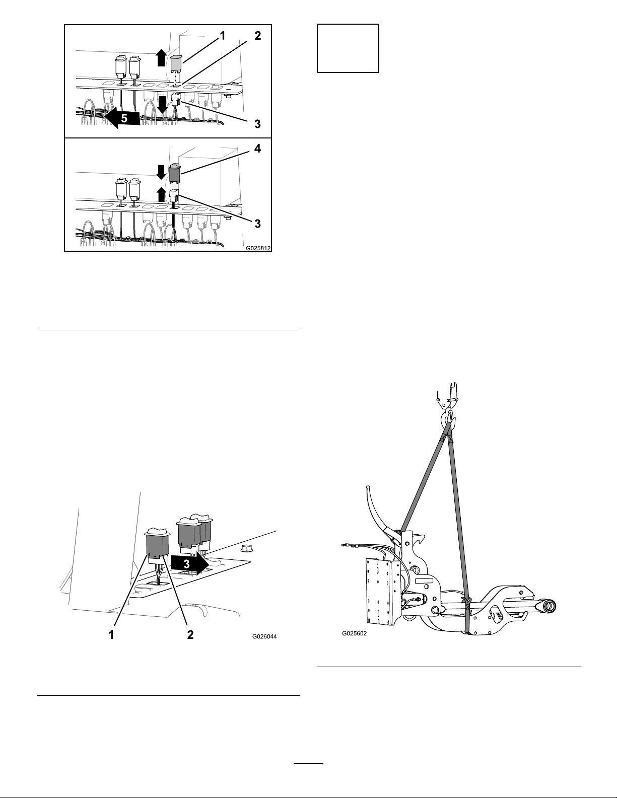
2.Removethe2ndleftmostand3rdleftmostblanking
platesfromthefromtheauxiliary-controlpanel(Figure
5).
3.Hex-angedbolts(12x30
mm)
1.2ndleft-most-switch
opening(auxiliary-control
panel)
2.Blankingplates
3.3rdleft-most-switch
opening(auxiliary-control
panel)
3.Pullthe2ndleftmostand3rdleftmost10-socket
connectorsofthewiringharnessofthemachine
throughtheswitchopeningswheretheblankingplugs
werelocated(Figure5).
4.Connectthe2ndand3rdleftmost10-socket
connectorsofthewiringharnesstothe10pin
connectorsofthe2oatswitches(Figure5).
5.Removethe4thrightmostblankingplatesfromthe
fromtheauxiliary-controlpane(Figure6).
4.10-socketconnector
5.Left
6.Switches(oat)
7
Page 8
2
PreparingtoInstallthe VibratoryPlow
NoPartsRequired
Procedure
1.Movethetractionunittoalevelsurfaceandlowerall
attachments.
2.Stoptheengine,settheparkingbrake,andremovethe
keyfromtheignitionswitch.
Figure6
1.Blankingplates3.10-socketconnector
2.4rdright-most-switch
opening(auxiliary-control
panel)
6.Pullthe4thrightmost10-socketconnectorsofthe
wiringharnessofthemachinethroughtheswitch
openingswheretheblankingplugswerelocated(Figure
6)
7.Connectthe4thrightmost10-socketconnectorofthe
wiringharnesstothe10pinconnectoroftherotation
switch(Figure6).
8.Rotatetheswitchessothatthelargenotchinthebody
oftheswitchesareforward,andsnaptheswitches
intotheswitchopeningsintheauxiliary-controlpanel
(Figure7).
4.Switch(rotation)
3.Cleantheangeandtherearmountingplateofthe
tractionunit.
4.Ifyouareremovingthetrencherinordertoinstallthe
vibratoryplow ,cleanandcapthehydraulicttingsat
thetractionunitandthetrencher.
5.Securetheliftingequipmenttothetowerassembly
(Figure8).
Important:Ensurethattheliftingequipmenthas
aliftingcapacityofatleast794kg(1750lb).
Figure7
1.Smallnotch
2.Largenotch
9.Securethecoverplatetothebulkheadwiththe6
hex-headbolts(12x30mm)thatyouremovedinstep
1.
3.Forward
Figure8
6.Raisethetowerassemblyofftheoorasshownin
Figure8.
8
Page 9
3
InstalltheCounterweightto
theTowerAssembly
Partsneededforthisprocedure:
1Towerassembly
1
Counterweightassembly
2
Hex-headbolt(1x8-1/2inch)
2
Hex-headbolt(1x3-1/2inch)
6
Washer(1inch)
6
Locknut(1inch)
Procedure
1.Useliftingequipmenttoraisethecounterweight.
Important:Ensurethattheliftingequipmenthas
aliftingcapacityofatleast743kg(1638lb).
Figure10
1.Locknut(1inch)4.Row3holes(for
2.Washer
3.Counterweight-mounting
hole
machineswith
wheels—2outerholes
only)
5.Row2holes(for
machineswithatrack
drive—2outerholesonly)
6.Hex-headbolt(1x3-1/2
inch)
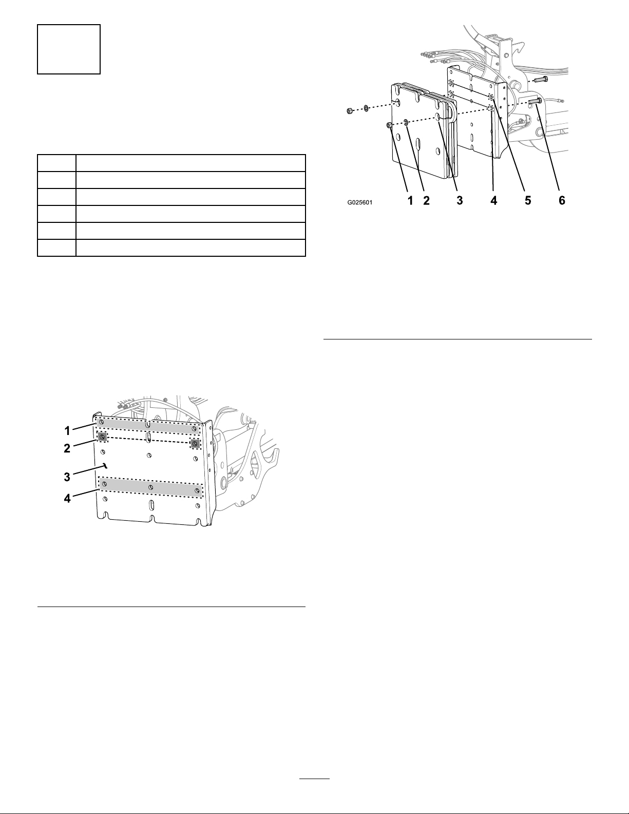
2.Identifytherowsofholesinthemountingplateof
thetowerassemblythatyouwillusetosecurethe
counterweightforyourmachine(Figure9).
Figure9
1.Row1holes/slot
2.Row2holes/slot
(counterweight-mounting
holes—2outerholesonly)
3.Mountingplate
4.Row4holes
3.Alignthe2counterweight-mountingholeswiththe
outerRow2holesofthetowermountingplate(Figure
9andFigure10).
4.Securethecounterweighttothemountingplatewith
2bolts(1x3-1/2inch),2washers(1inch),and2
locknuts(1inch);refertoFigure10.
Note:Thewashersandlocknutsaligninsidethe
counterboreofthecounterweight,withthewashers
betweenthelocknutsandthecounterweight(Figure
10).
5.Tightentheboltsandnutsto1219to1490N-m(899
to1099ft-lb).
6.Assemble2hex-headbolts(1x8-1/2inch)and2
washersintothe2outer-toprowofmountingholesfor
thetowerassembly(Figure11).
Note:Ensurethatthecounterboresideofthe
counterweight-mountingholesarealignedawayfrom
thefaceofthemountingplateofthetowerassembly.
9
Page 10
4
PreparingtoInstalltheTower andCounterweightAssembly
Partsneededforthisprocedure:
2
Locknut(1inch)
Procedure
Figure11
1.Tower/counterweight
assembly
2.Washer(1inch)
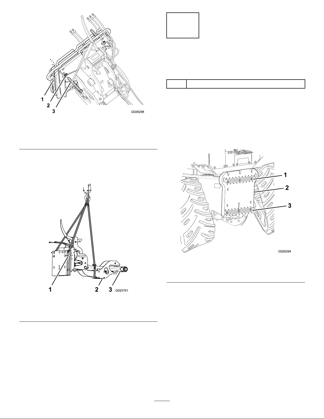
7.Locatetheliftingequipmentsothatitsupportsthe
counterweightandtoweratthe2liftingeyesofthe
counterweightandthecradleandlowerstrut(Figure
12).
3.Hex-headbolt(1x8-1/2
inch)
1.Locatetheholesandslotsinthemountingplateofthe
tractionunitformountingthetowerandcounterweight
assembly.
•Formachineswiththetrackdrive,usethe25
mm(1inch)holes/slotatRows2and5(Figure13).
Figure13
1.Counterweight-liftingeye
2.Cradle
Figure12
1.Row2holes3.Row5holesandslot
2.Rearmountingplate
•Formachineswithwheels,usethe25mm(1
inch)slots/holesatRows1and4(Figure14).
3.Lowerstrut
10
Page 11
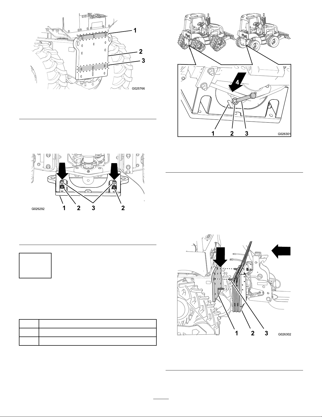
Figure14
1.Row1slots3.Row4holesandslot
2.Rearmountingplate
2.Formachineswithwheeldrive—fromunderthe
backofthemachine,insert2locknutsintothenut
retainerslocatedattheforward-outboardfaceofthe
rear-attachmentmountingplate(Figure15).
Figure15
1.Mountingplate(traction
unit)
2.Nutretainer
3.Locknut
Figure16
1.Row5slot,rearmounting
plate
2.Washers(1inch)
2.Positionthetowerandcounterweightassemblyas
follows:
3.Hex-headbolts(1x8-1/2
inch)
4.Rearward
•Formachineswiththetrackdrive—alignthe2
hex-headbolts(1x8-1/2inch)thatyouinstalled
instep6of4PreparingtoInstalltheTowerand
CounterweightAssembly(page10)withtheRow2
holesinthemountingplateofthetractionunitthat
youidentiedinFigure13;refertoFigure17.
5
InstallingtheTowerand CounterweightAssembly
Partsneededforthisprocedure:
4
Hex-headbolts(1x8-1/2inch)
8
Washers(1inch)
6
Nuts(1inch)
AligningtheTowerandCounterweight
AssemblytotheMachine
1.Insert1hex-headbolt(1x8-1/2inch)andwasher(1
inch)throughthecenterRow5slot(Figure16).
1.Rearmountingplateon
thetractionunit
2.Bolt(1x8-1/2inch)
•Formachineswithwheeldrive—alignthe2
hex-headbolts(1x8-1/2inch)thatyouinstalledin
11
Figure17
3.Counterweight
Page 12
step6of2PreparingtoInstalltheVibratoryPlow
(page8)withtheRow1slotsinthemountingplate
ofthetractionunitthatyouidentiedinFigure14;
refertogure17.
Figure20
Figure18
1.Rearmountingplateon
thetractionunit
2.Bolt(1x8-1/2inch)
3.Counterweight
3.Movethetowerandcounterweightassemblytoward
themachineuntilthebolts(1x8-1/2inch)are
partiallyinsertedthroughtheadjacentholesonthe
counterweightandmountingplates.
RemovingtheSwingCylinder
1.Disconnecttheextend,extendcrossover,andretract
crossoverhosesfromthehydraulicttingsintheswing
cylinder(Figure19).
1.Plug
2.Upperswing-lug
3.Rodtting
3.Removethespringpinfromtheswing-lugspacerfor
theswingcylinder.
Figure21
1.Springpin
2.Swing-lugspacer4.Swingcylinder
3.Wristpin
4.Removethewristpinfromtheswing-lugsandrod
tting(Figure20andFigure21).
Figure19
1.Extendhose3.Retract-crossoverhose
2.Extend-crossoverhose
2.Usingawrenchwithasquaredrive,removetheplug
fromtheupperswing-lug(Figure20).
5.Removethelowersnapringfromthepivotpinatthe
forwardendoftheswingcylinder(Figure22).
12
Page 13
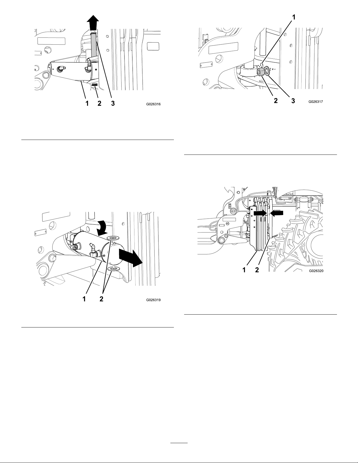
Figure22
1.Swingcylinder3.Pivotpin(swingcylinder)
2.Lower-snapring
6.Raisethepivotpinuntiltheswingcylinderisfreefrom
theforwardmountinglugs(Figure22).
Note:Useapieceoftapetoholdthepivotpinup.
7.Removetheswingcylinderandthe2washers(1-1/4
inch)fromtheswingframe(Figure23).
Note:Thesingcylinderweightsapproximately17kg
(38lb).
Figure24
1.Bolt(1x8-1/2
inch)—centerRow-5
holeinthetower-mounting
plate
2.Locknut(1inch)
3.Washer(1inch)
Note:Movethetowerandcounterweightassembly
towardthemountingplateofthemachineasneededto
threadthenutontothebolt(Figure25).
Figure25
Machinewithtracksshown;alsoappliestoamachinewith
wheels
Figure23
1.Swingcylinder2.Washers(1-1/4inch)
AssemblingtheTowerand
CounterweightAssemblytothe
Machine
1.Threadalocknut(1inch)andwasher(1inch)ontothe
lowercenterbolt(1x8-1/2inch)thatyouinstalledin
step1ofAssemblingtheTowerandCounterweight
AssemblytotheMachine(page13);refertoFigure24.
1.Towerandcounterweight
2.Mountingplate(machine)
2.Insert2bolts(1x8-1/2inch)intotheoutboardholes
inRow5andabolt(1x8-1/2inch)inthecenterslot
inRow1ofthetower-mountingplate(Figure26).
Note:Formachineswithwheel—threadthe2
outboardboltsintothenutsinthenutretainersthat
youinstalledinstep2of4PreparingtoInstallthe
TowerandCounterweightAssembly(page10).
13
Page 14
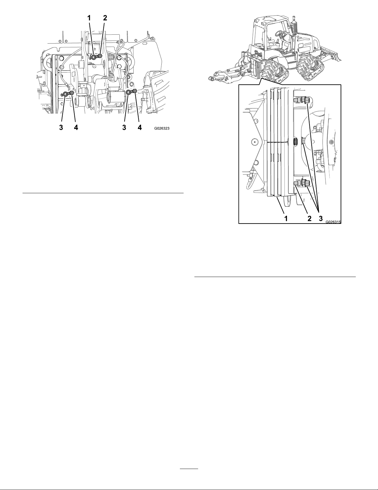
Figure26
Machinewithtracksshown;alsoappliestoamachinewith
wheels
1.Washer—Row1slot3.Washers—outerRow5
2.Bolt(1x8-1/2inch)—Row
1slot
holes
4.Bolt(1x8-1/2inch)—outer
Row5holes
3.Assemblethenutsandwashersasfollows:
•Formachineswiththetrackdrive—threadthe5
locknuts(1inch)and5washers(1inch)ontothe
shanksofthe5bolt(1x8-1/2inch)attheforward
sideofthemountingplateforthemachine(Figure
27).
Figure27
Bottomview
1.Towerandcounterweight
assembly
2.Bolt(1x8-1/2inch)
3.Locknutandwasher(1
inch)
•Formachineswithwheeldrive—atthetop
forwardsideofthemountingplateforthemachine,
threadthe3locknuts(1inch)and3washers(1
inch)ontotheshanksofthe3bolt(1x8-1/2inch)
forRow1(Figure28).
14
Page 15
InstallingtheSwingCylinder
1.Inserttheswingcylinderbetweenthemountinglugs
atthetower-mountingplateandtheswinglugsatthe
swingframe(Figure29).
Figure29
Figure28
1.Bolt(1x8-1/2inch)3.Locknut(1inch)
2.Washer(1inch)
4.Torquethebottomcenterbolt(1x8-1/2inch)and
locknutto1219to1490N-m(899to1099ft-lb).
5.Torquetheother5bolts(1x8-1/2inch)andlocknuts
to1219to1490N-m(899to1099ft-lb).
1.Upper-mountinglug
(swingframe)
2.Rodtting
3.Swingcylinder
4.Washer
5.Mountinglugs
(tower-mountingplate)
2.Insertthe2washers(1-1/4inch)betweentheforward
swingcylindermountingpointandthemountinglugs
attheswingframe(Figure29).
3.Alignholesinthecylinder,washersandlugs,andinsert
thepivotpinthroughtheholes(Figure22).
4.Securethepivotpinwiththesnapring(Figure22)that
youremovedinstep5ofRemovingtheSwingCylinder
(page12).
5.Alignholeintherodttingwiththeholesintheswing
lugsoftheswingframe(Figure21)
6.Installthewristpinthroughtheholesintherodtting
andswinglugs(Figure21).
Note:Ensurethatthecrossdrilledholeinthe
wristpinisalignedwiththecrossdrilledholeinthe
swing-lugspacer
7.Installthespringpin(Figure21)thatyouremoved
instep3ofRemovingtheSwingCylinder(page12)
throughthecrossdrilledholesintheswing-lugspacer
andwristpin.
8.Installtheplug(Figure20)thatyouremovedinstep2
ofInstallingtheSwingCylinder(page15).
9.Connecttheextend,extendcrossover,andretract
crossoverhosesthatyouremovedinstep1of
RemovingtheSwingCylinder(page12)tothehydraulic
ttingsintheswingcylinder(Figure19).
15
Page 16

6
ConnectingtheLiftandSwing
CylinderHoses
Partsneededforthisprocedure:
4
Connectortting(3/8inch)
InstallingtheLiftandSwingCylinder
Hoses
1.Wipecleantheareaaroundtheplugsattherearsideof
theauxiliary-hydraulicmanifold(Figure30).
1.PortA7
(auxiliary-hydraulic
manifold)
2.PortB7
(auxiliary-hydraulic
manifold)
3.PortA2
(auxiliary-hydraulic
manifold)
4.PortB2
(auxiliary-hydraulic
manifold)
Figure31
5.Left-swingcylinderhose
6.Right-swingcylinderhose
7.Lift-cylinderhose(retract)
8.Lift-cylinderhose(extend)
Figure30
1.Auxiliary-hydraulic
manifold
2.Plug
2.Removethe4plugs(3/8inch)atportsA2,B2,A7,and
B7(Figure30)fromauxiliary-hydraulicmanifoldatthe
followingportlocations.
3.Installthe4connectorttings(3/8inch)intoportsA2,
B2,A7,andB7ofthemanifold(Figure30).
4.Torquetheconnectorttingsto15to20N-m(132
to180in-ft).
5.Installthehosefromthettingintheretractportof
theliftcylindertotheconnectorttinginportA2
(Figure31andFigure32).
3.Port
4.Connectortting
Figure32
1.Liftcylinder
2.Lift-cylinderhose(extend)5.Left-swingcylinderhose
3.Lift-cylinderhose(retract)
6.Installthehosefromthettingintheextendportof
theliftcylindertotheconnectorttinginportB2
(Figure31andFigure32).
7.Installthehosefromthettingintheleft-swing
cylindertotheconnectorttinginportA7(Figure31,
Figure32,andFigure33).
16
4.Right-swingcylinderhose
Page 17

Figure33
2.Settheparkingbrakeandmovethecontrolsofthe
tractionunittotheNeutralposition;refertothe
Operator’sManualforthetractionunit.
3.Startthetractionunit;refertotheOperator’sManualfor
thetractionunit.
4.Pressbutton5ontheHomescreenofthecommand
centertotoggletothevibratoryplowfunction(Figure
35).
1.Left-swingcylinderhose
2.Right-swingcylinderhose
8.Installthehosefromthettingintheright-swing
cylindertotheconnectorttinginportB7(Figure31,
Figure32,andFigure33).
9.Torquethehosettingsto20to28N-m(180to252
in-ft).
PurgingAirfromtheLiftandSwing
Cylinders
DANGER
Pressingtheelevationoatswitchortheswingoat
whileyouarebleedingthehydraulicsystemwill
causetheattachmenttomoveuncontrollablyand
mayresultinpersonalinjuryordeath,ordamage
theattachment.
Donotpresstheelevationoatswitchortheswing
oat(Figure34).
Figure35
1.Button5
5.Performthefollowingtopurgeairfromthelift
cylinder:
A.Movethebackllblade/vibratoryplowjoystick
rearwardtoraisethecradleandlowerlink(Figure
36).
Figure34
1.Donotpresstheseswitches.
1.Ensurethattheareasurroundingthevibratoryplowis
clearofallpeopleandobjects.
Figure36
1.Backllblade/vibratory
plowjoystick
2.Raise
3.Lower
4.Swingleft
5.Swingright
B.Removetheliftingequipmentfromthetower
assembly.
C.Movethebackllblade/vibratoryplowjoystick
rearwardtoraisethecradleandlowerlink(Figure
36).
17
Page 18

Important:Donotallowthecradleorlower
linktostriketheground.
Note:Theliftcylinderwillmovethecradleand
lowerlinksmoothlywhentheairisbleedfrom
thecylinder.
D.Repeatsteps5Aand5Cuntiltheliftcylinder
movesthecradleandlowerlinkupanddown
smoothly.
6.Performthefollowingtopurgeairfromtheswing
cylinders:
A.Movethebackllblade/vibratoryplowjoystick
lefttoswingthecradleandlowerlinktotheleft
(Figure36).
B.Movethebackllblade/vibratoryplowjoystick
righttoswingthecradleandlowerlinktothe
right(Figure36).
C.Repeatsteps6Aand6Buntilthecradleandlower
linkswingleftandrightsmoothly
D.Usethebackllblade/vibratoryplowjoystickto
positionthecradleandlowerlinkthehorizontal
andstraightbehindthemachine.
7.Shutofftheengineandremovethekeyfromthekey
switch.
18
Page 19

7
InstallingtheShakerBox
NoPartsRequired
LiftingtheShakerBox
1.Insertthepin—51x355.6mm(2x14inch)through
theupper-mountbushingsandsecurethepinwiththe
anged-headbolt(16x60mm),spacer(1x5/8inch),
washer(5/8x3/4inch),andlocknut(16mm)hand
tight(Figure37).
Figure38
1.Pin—51x356mm(2x14
inch)
2.Side-plateopening
3.Lifttheshaker-boxassembly .
3.Lowermounting-plate
bushing
4.Rear-pivothole
(lower-strut)
InstallingtheShakerBox
1.Aligntheholesinthelowermounting-platebushings
intheshakerwiththerear-pivotholeinthelower-strut
(Figure38andFigure39).
Figure37
1.Pin—51x356mm(2x14
inch)
2.Upper-mountbushings
3.Flanged-headbolt(16x
60mm)
2.Attachtheliftingequipmentthroughtheopeningsin
thesideplatesoftheshakerboxandattachthelifting
equipmenttothepinthatyouinstalledinstep1(Figure
38).
4.Washer(1-3/4x5/8inch)
5.Spacer(1x5/8inch)
6.Locknut(16mm)
2.Insertthepin72x356mm(3x14inch)holesin
thelowermountingplatesandtherear-pivotofthe
lower-strut,andsecurethepinwiththeanged-head
bolt(16x60mm),washer(1-3/4x5/8inch),spacer(1
x5/8inch),andlocknut(16mm).
19
Page 20

Figure40
Figure39
1.Locknut(16mm)4.Washer(1-3/4x5/8inch)
2.Spacer(1x5/8inch)
3.Flanged-headbolt(16x
60mm)
5.Lowermounting-plate
bushing
6.Pin72x356mm(3x14
inch)
3.Alignthetiltcylinderwiththe2hydraulicportsupand
rearward.
1.Tilt-cylinderhydraulicports
2.Flanged-headbolt(16x
110mm)
3.Washer(1-3/4x5/8inch)8.Pin(2x14inch)
4.Spacer(1x5/16inch)9.Bushings(side
5.Spacer(2x2inch)
6.Locknut(16mm)
7.Barrel(tiltcylinder)
swing-frameplates)
4.Aligntheforward-pivotholeinthebarrelofthetilt
cylinderwiththebushingsinthesideswing-frame
plates.
5.Securethetiltcylindertotheswing-frameplateswith
apin(2x14inch),anged-headbolt(16x110mm),
washer(1-3/4x5/8inch),spacer(1x5/16inch),
spacer(2x2inch),andalocknut(16mm).
6.Removetheliftingequipmentfromthepinattheupper
mountingbushingattheshakerbox.
Note:Continuesupportingtheshakerboxwithlifting
equipmentatthesideplatesoftheshaker.
20
Page 21

Figure41
1.Tilt-cylinderhydraulicports
2.Flanged-headbolt(16x
60mm)
3.Washer(1-3/4x5/8inch)7.Locknut(16mm)
4.Spacer(1x5/8inch)8.Pistontting
5.Pin—51x356mm(2x14
inch)
6.Upper-mountbushings
7.Removethepin,anged-headbolt,spacer,washer,
andlocknutthatyouinstalledinstep1ofLiftingthe
ShakerBox(page19).
8
InstallingtheTiltandTrim CylinderHoses
Partsneededforthisprocedure:
4
Connectortting(3/8inch)
3
Squarenut(5/16inch)
10
Clampblock(2hose)
3
Coverplate
3
Washer(5/16inch)
3
Bolt(5/16x2-3/4inch)
2
Squarenut(3/8inch)
2
Clampblock(3hose)
2
Bolt(3/8x2-3/4inch)
2
Washer(3/8inch)
1Bar
InstallingtheTilt-CylinderHoses
1.Removethe4plugs(3/8inch)atportsA3,B3,A4,and
B4fromauxiliary-hydraulicmanifoldatthefollowing
portlocations(Figure42).
8.Alignthepistonttingofthetiltcylinderwiththe
upper-mountbushings.
9.Securethetiltcylindertotheupper-mountbushings
withthepin51x356mm(2x14inch),anged-head
bolt(16x60mm),washer(1-3/4x5/8inch),spacer
(1x5/8inch),andlocknut(16mm)
10.Tightentheanged-headboltandlocknutssecurethe
pinsatthelowerstrutandtiltcylinder202to248N-m
(149to184in-lb).
Figure42
1.Plug
2.Connectortting
2.Installthe4connectorttings(3/8inch)intoportsA3,
B3,A4,andB4ofthemanifold(Figure42).
3.Torquetheconnectorttingsto15to20N-m(132
to180in-ft).
4.Routethetilt-down(retract)hoseformtheforward
portofthetiltcylindertotheconnectorttinginport
B4ofthemanifold,andconnectthehosetothetting
handtight(Figure43).
21
Page 22

Figure43
1.Clampblock(tiltcylinder)4.Tilt-down(retract)hose
2.Clampblock(right
swing-frameplate)
3.Tilt-up(extend)hose
5.PortA4
(auxiliary-hydraulic
manifold)
6.PortB4
(auxiliary-hydraulic
manifold)
5.Routethetilt-up(extend)hoseformtherearportof
thetiltcylindertotheconnectorttinginportA4,and
connectthehosetothettinghandtight(Figure43).
6.Insertasquarenut(5/16inch)intotheslotintheclamp
supportlocatedontherightsideofthetiltcylinderand
therightswing-frameplate(Figure44andFigure45).
Figure45
1.Tilt-down(retract)hose5.Clampblock(2-hose)
2.Tilt-up(extend)hose6.Coverplate
3.Clampsupport(right
swing-frameplate
location)
4.Squarenut(5/16inch)8.Bolt(5/16x2-3/4inch)
7.Washer(5/16inch)
7.Looselysupportthe2tiltcylinderhoseswith4ofthe
clampblock(2-hose),coverplate,washer(5/16inch),
andbolt(5/16x2-3/4inch)attheclampsupportat
thetiltcylinder(Figure44).
8.Looselysupportthe2tiltcylinderhoseswith4ofthe
clampblock(2-hose),coverplate,washer,andbolt
(5/16x2-3/4inch)attheclampsupportattheright
swing-frameplate(Figure45).
Figure44
1.Clampsupport(tilt-cylinder
location)
2.Squarenut(5/16inch)6.Coverplate
3.Clampblock(2-hose)7.Washer(5/16inch)
4.Tilt-down(retract)hose8.Bolt(5/16x2-3/4inch)
5.Tilt-up(extend)hose
22
Page 23

InstallingtheTrim-CylinderHoses
1.Routethetrim-lefthosefromtheretractportofthe
right-trimcylindertotheconnectorttinginportB3
oftheauxiliary-hydraulicmanifoldandconnectthe
hosetothettinghandtight(Figure46).
Figure48
Figure46
1.Clampblock(tiltcylinder)4.Trim-lefthose
2.Clampblock(right
swing-frameplate)
3.Trim-righthose6.PortB3
5.PortA3
(auxiliary-hydraulic
manifold)
(auxiliary-hydraulic
manifold)
1.Clampsupport(trail-frame
location)
2.Squarenut(5/16inch)6.Washer(5/16inch)
3.Clampblock(2-hose)7.Coverplate
4.Trim-lefthose
5.Bolt(5/16x2-3/4inch)
8.Trim-righthose
3.Routethetrim-righthosefromtheextendportofthe
right-trimcylindertotheconnectorttinginportA3
ofthemanifold,andconnectthehosetothetting
handtight(Figure46).
4.Atthetiltcylinder,alignthetrim-leftandtrim-right
hosesintotheclampblocks(Figure49)thatyou
installedinstep7ofInstallingtheTilt-CylinderHoses
(page21)andtightenthebolt(5/16x2-3/4inch)to
1978to2542N-cm(175to225in-lb).
Figure47
1.Retractport(right-trim
cylinder)
2.Extendport(right-trim
cylinder)
3.Trim-lefthose6.Clampblock(tiltcylinder)
4.Trim-righthose
5.Clampblock(trail-frame)
2.Insertasquarenut(5/16inch)intotheslotintheclamp
supportlocatedontherightsideofthetrail-frame
plate(Figure48).
Figure49
1.Trim-lefthose4.Coverplate
2.Trim-righthose
3.Clampsupport(tilt-cylinder
location)
5.Washer(5/16inch)
6.Bolt(5/16x2-3/4inch)
5.Attherightswing-frameplate,alignthetrim-leftand
trim-righthosesintotheclampblocks(Figure50)that
youinstalledinstep8ofInstallingtheTilt-Cylinder
23
Page 24

Hoses(page21),andtightenthebolt(5/16x2-3/4
inch)to1978to2542N-cm(175to225in-lb).
Figure50
1.Trim-lefthose4.Coverplate
2.Trim-righthose
3.Clampsupport(right
swing-frameplate
location)
5.Washer(5/16inch)
6.Bolt(5/16x2-3/4inch)
9
InstallingtheHydraulicMotor Hoses
NoPartsRequired
PreparingtoInstalltheHydraulicMotor
Hoses
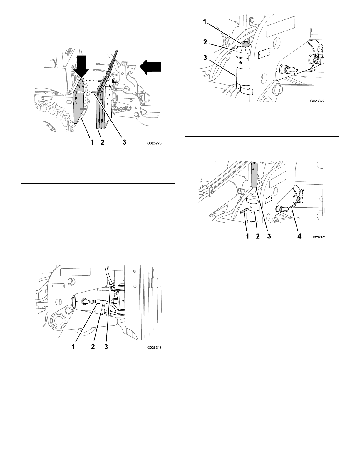
1.Attherearbulkheadofthemachine,removethe
2caps(1inch)fromthehydraulic-pressureand
hydraulic-returnttingsandthecap(5/8inch)from
thecase-draintting(Figure51).
6.Atthetrailframe,securethetrim-leftandtrim-right
hoses(Figure48)withthe2clampblocks,bolt(5/16x
2-3/4inch),washer(5/16inch),andcoverplate,and
tightenthebolt(5/16x2-3/4inch)to1978to2542
N-cm(175to225in-lb).
7.Torquethehosettingsateachendofthetilt-down
(retract)hose,tilt-up(extend)hose,trim-lefthoseand
trim-righthoseto46to57N-m(34to42ft-lb)
Figure51
1.Hydraulic-pressuretting
(1inch,portA)
2.Case-draintting(5/8
inch)
3.Hydraulic-returntting(1
inch,portB)
4.Cap(1inch)9.45°elbowtting(3/4inch)
5.Cap(5/8inch)
6.Tube-elbow(3/4inch)
7.Swiveltee(1x3/4x3/4
inch)
8.Checkvalve
24
Page 25

2.Attherearbulkhead,assemblethe2swiveltees(1x
3/4x3/4inch)ontothehydraulicpressure(portA)
andhydraulicreturn(portB)ttingsandtightenthe
ttingshandtight(Figure51).
3.Assemblethe2tube-elbows(3/4inch)andthecheck
valveontothetube-elbowsandtightenthetubettings
handtight(Figure51).
Note:Ensurethattheow-directionarrowonthe
checkvalveispointinglefttoright.
4.Tightenthetubenutsofthetube-elbowsto90to111
N-m(66to82ft-lb).
Tightenthecompressionnuts(1inch)oftheswivel
ttingsto122to149N-m(90to110ft-lb).
5.Assemblethe45°elbowtting(3/4inch)ontothe
swiveltee(1x3/4x3/4inch)atthehydraulicreturn
(portB)andtightenthettingshandtight.
6.Insertthe2squarenuts(3/8inch)intotheclamp
supportsattheleftsideofthetiltcylinder(Figure52).
Figure53
1.Case-drainhose2.45°tting(5/8inch)—top
ofthehydraulicmotor
Figure52
1.Squarenut(3/8inch)2.Clampsupport
InstallingtheHydraulicMotorHoses
1.Routethecase-drainhosefromthe45°tting(5/8
inch)atthetopofthehydraulicmotor,alongtheleft
sideofthetiltcylinder,andtothebulkheadtting(5/8
inch)attherearbulkheadofthemachine(Figure53
andFigure54).
Figure54
1.Swiveltee(1x3/4x3/4
inch)
2.Bulkheadtting(5/8inch)5.Case-drainhose
3.45°elbowtting(5/8inch)
4.Returnhose
6.Pressurehose
2.Routethereturnhosefrom90°tting(3/4inch)at
portBofthehydraulicmotor(Figure54andFigure
55),alongtheleftsideofthetiltcylinder,andtothe
45°elbowtting(3/4inch)thatyouassembledinstep
5ofPreparingtoInstalltheHydraulicMotorHoses
(page24).
25
Page 26

Figure55
1.Returnhose
2.90°tting(3/4inch)—port
Bofthehydraulicmotor
3.Routethepressurehosefromthe90°tting(3/4inch)
attheleftsideofthehydraulicmotortotheswiveltee
(1x3/4x3/4inch)connectedtohydraulicpressure
(portA)ofrearbulkheadofthemachine(Figure
54andFigure56);refertostep2of9Installingthe
HydraulicMotorHoses(page24).
Figure57
1.Bar5.Pressurehose
2.Bolt(3/8x2-3/4inch)6.Case-drainhose
3.Washer(3/8inch)
4.Clampblock(3hose)
7.Returnhose
5.Alignthereturnhoseinthetopgrooveoftheclamp
block,thecase-drainhoseinthemiddlegroove,and
thepressurehoseinthebottomgroove.
6.Securethehoseswiththeotherclampblock(3hose),2
bolt(3/8x2-3/4inch),andwasher(3/8inch).
7.Torquetheboltto37to45N-m(27to33ft-lb).
8.Torquethe45°elbowtting(3/4inch)thatyou
assembledinstep5ofPreparingtoInstallthe
HydraulicMotorHoses(page24)to90to111N-m
(66to82ft-lb).
9.Torquethettingsforthepressureandreturnhosesto
90to111N-m(66to82ft-lb).
10.Torquethettingsforthecase-drainhoseto58to72
N-m(43to53ft-lb).
Figure56
1.Pressurehose
2.90°tting(3/4inch)—left
sideofthehydraulicmotor
4.Alignthebarand1clampblock(3hose)betweenthe
hydraulicmotorhosesandtheclampsupportonthe
leftsideofthetiltcylinder.
26
Page 27

10
BleedingtheAirfromtheTilt
andTrimCylindersandthe
HydraulicMotor
NoPartsRequired
BleedingtheAirfromtheTiltandTrim
Cylinders
DANGER
Pressingtheelevationoatswitchortheswingoat
whileyouarebleedingthehydraulicsystemwill
causetheattachmenttomoveuncontrollablyand
mayresultinpersonalinjuryordeath,ordamage
theattachment.
Donotpresstheelevationoatswitchortheswing
oat(Figure58).
Figure59
1.Button5
5.Ensurethatthevibratoryplowislevel.
6.Performthefollowingtobleedthetiltcylinder:
Important:Donotallowtheshakerboxtostrike
theground.
A.Pressthelowerhalfofthetiltswitchtotiltthe
shakerboxup(Figure60).
B.Presstheupperhalfofthetiltswitchtotiltthe
shakerboxdown(Figure60).
C.Repeatsteps6Band6Auntilthetiltcylindertilts
theshakerboxsmoothly.
Figure58
1.Donotpresstheseswitches.
1.Ensurethattheareasurroundingthevibratoryplowis
clearofallpeopleandobjects.
2.Settheparkingbrakeandmovethecontrolsofthe
tractionunittotheNeutralposition;refertothe
Operator’sManualforthetractionunit.
3.Startthetractionunit;refertotheOperator’sManualfor
thetractionunit.
4.Pressbutton5ontheHomescreenofthecommand
centertotoggletothevibratoryplowfunction(Figure
59).
Figure60
1.Tiltswitch(up)2.Tiltswitch(down)
7.Performthefollowingtobleedthetrimcylinder:
A.Twistthumbcontrolforthebackll
blade/vibratoryplowjoystickclockwisetotrim
theshakerboxleft(Figure61).
B.Twistthumbcontrolforthebackll
blade/vibratoryplowjoystickcounterclockwiseto
trimtheshakerboxright(Figure61).
C.Repeatsteps7Aand7Buntilthetrimcylinder
rotatestheshakerboxsmoothly .
27
Page 28

Figure61
1.Shaker-trimright
2.Shaker-trimleft
3.Thumbcontrol
(attachmentjoystick)
BleedingtheAirfromtheHydraulic
Motor
1.Movethejoystickfortherearattachment-hydraulic
motorbackwardfromtheNeutralpositionuntilyou
feeltheplowbegintovibrate(Figure62).
Operation
UsingtheTransportLock
UnlockingtheTransportLock
1.Startthetractionunitandsettheparkingbrake.
2.Pressthetiltswitchupuntiltheshakerboxisfully
tiltedupandforward.
Important:Movingthevibratoryplowtothe
fully-raisedpositionwithoutrstfullytiltingthe
shakerforwardandupbeforeraisingtheplowwill
damagethetiltcylinder.
3.Slowlyraisethevibratoryplowtoitsfullheight;refer
toUsingtheBackllBlade/VibratoryPlowJoystick
(page30).
4.Pullforwardontheleverforthetransportlock(Figure
63).
2.Movethejoystickfortheattachment-hydraulicmotor
totheNeutralposition(Figure62).
Figure62
1.Vibratoryplow/trencher
motorjoystick
3.Movethejoystickback(towardyou)10%ofthetotal
travelandletshakerboxoperatefor20seconds(Figure
62).
4.Movethejoystickfortheattachment-hydraulicmotor
totheNeutralposition(Figure62).
5.Raisetheplowtothetransportposition,stopthe
engine,andremovethekeyfromthekeyswitch;refer
toLockingtheTransportLock(page28).
2.Joystickmovement
(neutraltoplowvibrate;
plowvibratetoNeutral)
Figure63
1.Cam
2.Hook
5.Lowertheplowuntilthecamontheupperstrutclears
thehookofthetransportlock(Figure63).
3.Transport-locklever
LockingtheTransportLock
1.Startthetractionunitandsettheparkingbrake.
2.Pressthetiltswitchupuntiltheshakerboxisfully
tiltedupandforward.
Important:Movingthevibratoryplowtothe
fully-raisedpositionwithoutrstfullytiltingthe
shakerforwardandupraisingthewilldamagethe
tiltcylinder.
28
Page 29

3.Slowlyraisethevibratoryplowtofullheight;referto
UsingtheBackllBlade/VibratoryPlowJoystick(page
30).
Note:Whenthevibratoryplowisinthefullup
position,thetransportlockwillautomaticallyengage
thecamontheupperstrut(Figure63).
Important:Beforemovingthetractionunitor
performingmaintenance,ensurethattheplowis
inthefulluppositionandcamontheupperstrut
fullyengagesthehookofthetransportlock.
UsingtheVibratoryPlow
UsingtheOperatorControls
UsingtheCommandCenter
Important:Donotswitchfromvibratoryplowoperation
tobackllbladeoperationwhilevibratory-plowmotor
isoperating.Damagetoshakerboxorvibratory-plow
motormayresult.
1.Button5(switchbetween
controllingthebackll
bladeorvibratoryplow)
2.Button7(increasethe
enginespeed)
3.Button8(decreasethe
enginespeed)
Figure64
4.Vibratoryplowicon
5.Backllbladeicon
Backllblade/VibratoryPlowCommandButton
Pressthebackllblade/vibratoryplowcommandbutton
(button5),locatedatthetop-rightcornerofthecommand
center(Figure64),toswitchbetweencontrollingthebackll
bladeorthevibratoryplowwiththebackllblade/vibratory
plowjoystick;refertoUsingtheBackllBlade/Vibratory
PlowJoystick(page30).
ThrottleButton
•Throttle-upbutton—pressthethrottle-upbutton(button
7),locatedatthebottom-rightcornerofthecommand
center,toincreasetheenginespeed(Figure64).
Note:Pressthebuttonrepeatedlytoincreasetheengine
speeduptothemaximumenginespeed(2,450rpm).
•Throttle-downbutton—pressthethrottle-downbutton
(button8),locatedatthebottom-rightcornerofthe
commandcenter,tolowertheenginespeed(Figure64).
Note:Pressthebuttonrepeatedlytodecreasetheengine
speeddowntotheengine-idlespeed(750rpm).
29
Page 30

UsingtheBackllBlade/VibratoryPlowJoystick
Note:Setthebackllblade/vibratoryplowcommand
button(button5)tothevibratoryplowfunctiontochange
theattachmentjoystickfunction;refertoUsingtheCommand
Center(page29).
BackllBlade/VibratoryPlowJoystick
•Movethebackllblade/vibratoryplowjoysticktoward
youtoraisetheelevationofthevibratoryplow(Figure65
andFigure66).
•Movethebackllblade/vibratoryplowjoystickaway
fromyoutolowertheelevationofthevibratoryplow
(Figure65andFigure66).
Figure67
ThumbControl
•Twistthumbcontrolforthebackllblade/vibratoryplow
joystickclockwisetotrimtheshakerboxleft(Figure65
andFigure68).
•Twistthumbcontrolforthebackllblade/vibratoryplow
joystickcounterclockwisetotrimtheshakerboxright
(Figure65andFigure68).
Figure65
1.Backllblade/vibratory
plowjoystick
2.Thumbcontrol
(attachmentjoystick)
3.Shaker-trimleft7.Swingleft
4.Shaker-trimright8.Swingright
5.Raise
6.Lower
Figure66
Figure68
UsingtheVibratoryPlow/TrencherMotorJoystick
•Movethevibratoryplop/trenchermotorjoystickbackto
startthehydraulicmotorfortheshakerbox(Figure69).
Note:Movingthejoystickclosertoyouincreasesthe
vibrationintensityoftheplow.
•Movethevibratoryplow/trenchermotorjoysticktoward
theNeutralpositiondecreasesthevibrationintensityof
theplow(Figure69).
•Movethevibratoryplow/trenchermotorjoysticktothe
neutralpositiontostopthevibrationfunctionofthe
plow(Figure69).
•Movethebackllblade/vibratoryplowjoysticktotheleft
toswingthevibratoryplowleft(Figure65andFigure67).
•Movethebackllblade/vibratoryplowjoysticktothe
righttoswingthevibratoryplowright(Figure65and
Figure67).
30
Page 31

Figure71
Figure69
1.Vibratoryplow/trencher
motorjoystick
UsingtheTiltSwitch
2.Joystickmovement
(neutraltoplowvibrate;
plowvibratetoNeutral)
Thetiltswitchislocatedattheauxiliarycontrolpanelandis
the4thswitchfromtheleft(Figure70).
UsingtheElevation-oatSwitch
Note:Thevibratoryplowhas2operationmodesthatyou
canusetheelevation-oatswitchtocontrol:
Floatposition—theplowwillfollowthecontourofthe
groundwhentheelevation-oatswitchtotheoatposition.
Off(xed-position)—theplowwillstopmovingoroating
whenyoumovetheelevation-oatswitchtotheoffposition.
•Presstheupperhalfoftheelevation-oatswitchtoallow
theplowtofollowthecontouroftheground(oat)
withoutmanualmovementofthebackllblade/vibratory
plowjoystick(Figure70andFigure72).
•Pressthelowerhalfoftheelevation-oatswitchtoshut
offtheelevation-oatfunctionandcontroltheelevation
oftheplowwiththebackllblade/vibratoryplowjoystick
(Figure70).
Figure70
1.Tiltswitch
2.Elevation-oatswitch
3.Swing-oatswitch
•Presstheupperhalfofthetiltswitchtorotatetheshaker
boxup(Figure70andFigure71).
•Pressthelowerhalfofthetiltswitchtorotatetheshaker
boxdown(Figure70andFigure71).
Figure72
UsingtheSwing-oatSwitch
Note:Thevibratoryplowhas2operationmodesthatyou
canusetheswing-oatswitchtocontrol:
Floatposition—theplowwillfollowthemovearound
undergroundobstructionswhentheswing-oatswitchto
theoatposition.
Off(xed-position)—theplowwillstopmovingoroating
whenyoumovetheswing-oatswitchtotheoffposition.
•Presstheupperhalfoftheswing-oatswitchtoallowthe
plowtomovearoundburiedobstructions(oat)without
manualmovementofthebackllblade/vibratoryplow
joystick(Figure70andFigure73).
•Pressthelowerhalfoftheoat-oatswitchtoshutoff
theswing-oatfunctionandcontrolthepositionofthe
plowwiththebackllblade/vibratoryplowjoystick
(Figure70).
31
Page 32

Figure73
InstallingandRemovingtheVibratory
PlowBlade
InstallingthePlowBlade
Note:Thefollowingstepsaregeneralinstructionsfor
installingtheplowblade.forspecicinstructionsoninstalling
yourblade,refertotheoperator’smanualsuppliedwiththe
bladefromtheblademanufacturer.
1.Raisethevibratoryplowtothetransportposition;refer
toLockingtheTransportLock(page28).
Important:Ensurethatthecamontheupper
strutfullyengagesthehookofthetransportlock.
2.Securetheliftingequipmenttotheblade,andliftthe
bladetotheverticalposition.
3.Openthebalesofthesafetypins,removethesafety
pinsfromtheblade-mountingpins,andremovethe
blade-mountingpinsfromthestabilizer(Figure74).
7.Alignthelowerholeintheplowbladewiththe
mountingholeinthestabilizer.
8.Installtheblade-mountingpinthroughthemounting
holeinthestabilizerandthroughthelowerholeinthe
plowblade(Figure74).
Note:Ensurethattheheadofthepinisushwith
thesurfaceofthestabilizer.
9.Installthesafetypinsintotheholesintheblademountingpins,andclosethebalesoverthemounting
pins(Figure74).
10.Removetheliftingequipment.
RemovingthePlowBlade
1.Raiseorlowertheplowbladeuntilthebladeisslightly
abovetheground.
2.Secureliftingequipmenttotheblade,andlifttheblade
slightly.
3.Openthebalesforthesafetypins,andremovethe
safetypinsfromthemountingpins(Figure74).
4.Removethelowermountingpin(Figure74).
Note:Applyenoughliftingforcewiththelifting
equipmenttokeepthebladefromrotatingasyou
removethelowermountingpin.
Figure74
1.Plowblade
2.Blade-mountingpin4.Mountingslot
3.Safetypin
4.Centerablade-mountingpinintheupperholeofthe
blade(Figure74).
5.Alignthebladetothestabilizeroftheshaker,andalign
theblade-mountingpintothemountingslotinthe
frameofthestabilizer(Figure74).
6.Lowerthebladeandinsertthepinintotheslot.
5.Raisethebladeuntiltheuppermountingpinclearsthe
mountingslotintheframeofthestabilizer(Figure74).
6.Movetheliftingequipmentandthebladerearwarduntil
theplowbladeclearsthebackofthevibratoryplow .
7.Carefullylowertheplowbladeontoitsside.
8.Removetheliftingequipmentfromtheblade.
InstallingCableintotheCableChute
Thecablechuteisattachedtothebackoftheblade.Some
cablechuteshavereplaceablelinksandotherchutesare
attacheddirectlytotheblade.
Note:Thefollowingaregeneralinstructionsforloading
cableintothecablechute.Forspecicinstructiononusing
yourplowblade,refertotheOperator’ sManualprovidedby
theplowblademanufacturer.
1.Removethehairpinandthegatepinfromthegate
(Figure75).
Note:Ensurethattheheadofthepinsisushwith
thesurfaceofthestabilizer.
32
Page 33

Figure75
1.Plowblade
2.Hairpin
2.Pullthegateleverrearwardandrotatethegatedown
(Figure75).
3.Gatepin
4.Gatelever
WARNING
Vibrationsfromtheplowcancausethesoilofan
overhangorhighbanktofallandcauseinjuryor
death.
Keeppeopleandanimalsawayfromnearby
overhangsandhighbankswhileyouareoperating
thevibratoryplow.
SettingtheShoePositionontheStabilizer
Youcansetthewear-plateshoesforthestabilizerto2
positionsdependingonoperatingconditions,bladeselection,
andyourpreference.
Tochangethepositionofthestabilizershoes,performthe
followingsteps:
1.Raisethevibratoryplowtoanelevationthatallowsyou
toaccessthebottomofthestabilizershoes(Figure76).
3.Checkthelinksofthechuteforwearandfreedomof
movement;cleanorrepairthelinksbeforeinserting
thecableintothechute.
4.Insertthecableintothecablechute(Figure75).
5.Liftthegateleverupandrotatethegateforward
(Figure75).
6.Installthegatepinthroughtheholeintheretainerof
chute(Figure75).
7.Installthehairpinthroughthegatepin(Figure75).
PreparingtoUsetheCablePlow
WARNING
Seriousinjuryordeathcanresultfromcontactwith
theploworfromejecteddebrisduringplowing
operation.
Makesurethatallpeopleandanimalsareclear
ofthemachineandtheworksitewhileyouare
operatingthevibratoryplow.
Figure76
1.Wearplate5.Locknut
2.Flat-headscrews6.Wearplate—inboard
3.Stabilizershoe
4.Washer
2.Atthewearplate,removethe4atheadscrews,
locknuts,andwashersthatsecuretheplatetothe
stabilizershoe(Figure76).
position
7.Wearplate—outboard
position
WARNING
Vibrationsfromtheplowcancausethewallsofa
trenchtocollapse,causinginjuryordeath.
Neverallowpeopletostandinsideoforadjacent
toanearbytrenchwhileyouareoperatingthe
vibratoryplow .
3.Movethewearplatetoeitherinboardoroutboard
positiontoaligntheholesinthewearplatewiththe
holeinthestabilizershoe.(Figure76).
4.Securetheplatetothestabilizershoewiththebolts,
locknuts,andwashersthatyouremovedinstep2
(Figure76).
5.Torquethescrewsandnutsto37to45N-m(27to
33ft-lb).
33
Page 34

6.Repeatsteps1through5fortheotherwearplateand
stabilizershoe.
PositioningtheSeatforPlowing
Fastentheseatbeltandrotatetheseatclockwise.
Note:Y oumustbeseatedintheoperatorseatbeforemoving
thetractionunit;otherwise,theenginewillstopin1second.
PreparingtheTractionUnit
1.Starttheengineofthetractionunit;refertothe
Operator’sManualofthetractionunit.
2.Settheendingspeedtothe1/2throttleposition,and
allowtheenginetowarmupfor3to5minutes.
3.Ensurethatthevibratoryplowisinthetransport
position;refertoLockingtheTransportLock(page
28).
4.Movethetractionunittotheworksite.
PlowingCableandTubing
2.Insertthecablethatyouareinstallingattheworksite
intothechute;refertoInstallingCableintotheCable
Chute(page32).
3.Movethebackllblade/vibratoryplowjoysticktoward
youtolowertheplowbladetothesurfaceofthesoil.
Note:Anchortheendofthecableasnecessary.
Important:Donotstarttheblade-vibration
functionoftheplowuntilthebladehasentered
theground.
4.Releasetheparkingbrake;refertotheOperator’sManual
forthetractionunit.
5.Beginloweringthebladeintothegroundbyperforming
thefollowingsteps:
A.Presstheupperhalfoftheelevation-oatswitch
toallowtheplowtoFloatvertically(Figure78).
Note:Slowlylowerthebladeintotheground.
WARNING
Aworkingvibratoryplowcaninjureorkillyou.
Beforeyoubeginusingthevibratoryplow,make
surethatallpeopleareawayfromthedangerarea.
Figure77
1.Dangerarea(shadedareainthegure)
Figure78
1.Float(elevation-oat
switch)
B.Ontheutility-tractionjoystick,usethedown-shift
buttonofthegear-selectorswitchtoshiftthe
transmissiontogear1(Figure79).
Note:Whenyourststartthemachine,gear1
isselected.
2.Off(elevation-oatswitch)
Important:Youwillreducethelifeofthecableplowif
youoperatetheblade-vibrationfunctionwhiletheblade
isoutoftheground.
LoweringthePlowintotheGround
Important:Knowthelocationofallunderground
utilitiesbeforeoperatingtheequipmentontheworksite.
1.Releasethecableplowfromthetransportposition;
refertoUnlockingtheTransportLock(page28).
34
Page 35

Figure80
Figure79
1.Down-shiftbutton
(utility-tractionjoystick)
2.Up-shiftbutton
(utility-tractionjoystick)
3.Icon—gear-shiftpattern
C.Liftuponthelockringthatisatthebottomof
theutility-tractionjoystickandslowlypushthe
joystickforward(Figure80).
Important:Nevermovethetractionunitin
thereversedirectionwiththebladeinthe
ground.
Note:Useonlytheutility-tractionjoystickto
controltheforwardandreversedirectionsofthe
tractionunitwhileplowing.Thetractionunit
movesforwardorbackwardthroughacontinuous
rangeofspeedsdependingonthepositionofthe
utility-tractionjoystick.
Thefurtherthatyoupushtheutility-traction
joystickawayfromtheNeutralposition,thefaster
thetractionunittravels.Theleverstaysinposition
whenyoureleasethelockring.Movethejoystick
totheNeutralpositiontostopthetractionunit
fromtravelinginforwardorreverse.
1.Tractionunit—forward
2.Utility-tractionjoystick
3.Lockring
6.Oncethebladeenterstheground,beginthe
blade-vibrationfunctionbyliftinguponthelockring
thatisatthebottomofvibratoryplow/trenchermotor
joystickmovingthejoysticktowardyou(Figure81).
Figure81
1.Vibratoryplow/trencher
motorjoystick
2.Joystickmovement
(neutraltoplowvibrate)
Note:Ensurethatthechutelinksarehorizontalasthe
bladeenterstheground.
7.When1/4ofthebladeisbelowthesurfaceof
theground(Figure82),graduallyincreasethe
blade-vibrationfunctionbymovingthevibratory
plow/trenchermotorjoystickback(towardyou)and
selectingtheswing-oatswitch(Figure83)tothe
Floatposition.
35
Page 36

Figure82
Figure83
1.Float(swing-oatswitch)2.Off(swing-oatswitch)
Note:Thisletstheobstacletomovearoundsideof
theploworallowstheplowbladetomovearoundthe
obstacle
PlowingCablefromaBuildingWall
1.Digaholenexttothewallofthebuildingwherethe
cablewillenterthebuilding(Figure84).
Important:Youwilldamagethecableandthe
chuteifyouforcethebladeintothegroundtoo
fast.Ifyouareplowingintoveryhardground,you
canunintentionallyoverloadthebladeandthereby
under-powertheblade-vibrationfunction.
Note:Movetheutility-tractionjoystick(Figure80)
towardtheneutralpositioniftheplowbladerisesup
fromthegroundwhileyouareplowing.
8.Whenthebladeisdownatfull-plowingdepth,adjust
thevibratoryplow/trenchermotorjoysticksothatthe
blade-vibrationfunctionisfastenoughtoallowthe
tractionunittomaintainthedesiredgroundspeed
(Figure81).
Note:Donotoperatetheblade-vibrationfunction
fasterthannecessarytomaximizethespeed.
Important:Ifthetiresbegintoslipwhileyouare
plowing,reducetheforwardspeedofthetraction
unitbymovingtheutility-tractionlevertowardthe
Neutralposition.
9.Usetheutility-tractionjoysticktoincreasetheforward
travelspeeduntilthetiresbegintosliporlosetraction
(Figure80).
PlowingAroundanUndergroundObstacle
Figure84
1.Hole(outsideofbuilding)
2.Hole(throughthebuilding
wall)
3.Anchorpoint
2.Drillaholethroughthewallwherethecablewillenter
thebuilding(Figure84).
3.Movethetractionunittoapositionwhereyoucan
lowerthebladeintotheholenexttothebuilding
(Figure84).
4.Threadthecablethroughthechuteoftheblade,and
pushthecablethroughthewall.
5.Lowerthebladeintothehole(Figure84).
6.Anchortheendofthecableinsidethebuilding(Figure
84).
7.Slowlymovethetractionunitforward,andstartthe
blade-vibrationfunctionasthebladeentersthesoil
(Figure84).
8.Asthebladeentersthesoil,slowlyincreasethe
blade-vibrationfunctionbymovingthevibratory
plow/trenchermotorjoysticktowardyou;referto
UsingtheVibratoryPlow/TrencherMotorJoystick
(page30).
Performthefollowingstepsifyouencounteranunderground
obstaclewhileplowing:
1.Increasethevibrationspeedbymovingvibratory
plow/trenchermotorjoystickrearwardwhile
maintainingslightforwardpressureontheplowblade
andtheobstaclewiththetractionunit(Figure81).
2.MovetheswingcontroltotheFloatposition(Figure
83).
Important:Donotstarttheblade-vibration
functionoftheplowuntilthebladehasentered
theground.
PlowingaServiceConnection
Usethisproceduretoplowtoaserviceconnection,anchor
thecable,andplowtothenextserviceconnectionorend
thecablerun.
36
Page 37

1.Ensurethatthestabilizershoesaresettothewide
position;refertoSettingtheShoePositiononthe
Stabilizer(page33).
2.Digaserviceholedownwherethecablewilljointhe
serviceconnectiontotheplowingdepthofthecable
run(Figure85)andnowiderthan0.6m(24inches).
Note:Thetractionunitcandriveovera0.6m
(24-inch)hole.
Figure85
1.Servicehole2.0.6m(24inches)
3.Plowdirectlytotheserviceholewherethecablesjoins
theserviceconnection(Figure86).
plow/trenchermotorjoysticktowardyou;referto
UsingtheVibratoryPlow/TrencherMotorJoystick
(page30).
Important:Donotstarttheblade-vibration
functionoftheplowuntilthebladehasentered
theground.
PlowingTurnswithaRadiusLessThan0.9m(36
inches)
1.Atthelocationwherethecablewillturn,digaservice
holedowntotheplowingdepth(Figure85)ofthe
cablerunandnowiderthan0.6m(24inches).
2.Plowthecabletothehole(Figure87).
Figure86
1.Servicehole
2.Loopinthecable
4.Beforethebladeenterstheservicehole,stopthe
blade-vibrationfunctionbymovingthevibratory
plow/trenchermotorjoysticktotheNeutralposition.
5.Movethevibratoryplowbladeacrossthehole(Figure
86).
6.Feedthecabledownthroughthechute,andmakea
loopinthecableatthebottomofthehole(Figure86).
7.Whilefeedingthecableintothechute,movethe
tractionunitforwarduntilthebladeentersthesoilon
theothersideoftheservicehole(Figure86).
8.Asthebladeentersthesoil,slowlystartthe
blade-vibrationfunctionbymovingthevibratory
Figure87
1.Cable-plowrun#12.Cable-plowrun#2
3.Beforethebladeentersthehole,stopthe
blade-vibrationfunctionbymovingthevibratory
plow/trenchermotorjoysticktotheNeutralposition;
refertoUsingtheVibratoryPlow/TrencherMotor
Joystick(page30).
4.Selecttheswing-oatswitch(Figure83)totheOff
position;refertoUsingtheSwing-oatSwitch(page
31).
5.Whenthecablechuteofthebladeisintothehole,
performthefollowing:
A.Stopthetractionunit.
B.Removethegatefromthechuteoftheplowblade.
C.Removethecablefromthechute.
D.Carefullyraisethebladeoutofthehole
Note:Donotcutordamagethecablewhileraising
thebladeoutofthehole.
37
Page 38

6.Movethetractionunittothepositionthatalignsthe
plowbladewiththenextdirectionforthecablerun
andalongsidetheservicehole(Figure87).
7.Carefullylowerthebladeintotheservicehole.
8.Installthecableintothechuteandinstallthegateto
thechute;refertoInstallingCableintotheCableChute
(page32).
9.Whilefeedingthecableintothechute,movethe
tractionunitforwarduntilthebladeentersthesoilon
thesideoftheservicehole(Figure87).
10.Asthebladeentersthesoil,slowlystartthe
blade-vibrationfunctionbymovingthevibratory
plow/trenchermotorjoysticktowardyou.
Important:Donotstarttheblade-vibration
functionoftheplowuntilthebladehasentered
theground.
PlowingT urnswithaRadiusGreaterThan0.9m(36
inches)
Tomakearightturnwitharadiusgreaterthan0.9m(36
inches),performthefollowingsteps:
1.Selecttheswing-oatswitch(Figure83)totheFloat
position;refertoUsingtheSwing-oatSwitch(page
31).
2.Steerthebladeandtheshakerboxtotheright
byrotatingtheleft-thumbcontrolofthebackll
blade/vibratoryplowjoystickclockwise(Figure88);
refertoUsingtheBackllBlade/VibratoryPlow
Joystick(page30).
Note:Allowthebladetotraverseenoughdistanceto
movetothefarthestrightposition.
Figure89
1.Steeringwheel3.Leftturn(rear-wheel
steeringswitch)
2.Rightturn(rear-wheel
steeringswitch)
4.Usethethumbcontrolofthebackllblade/vibratory
plowjoysticktomaintainthedirectionofthevibratory
ploworchangethedirectionofthebladeandstabilizer;
refertoUsingtheBackllBlade/VibratoryPlow
Joystick(page30).
RaisingtheBladefromtheGround
DANGER
IftheswingcontrolisintheFloatpositionwhen
thebladeoftheplowisoutoftheground,theplow
mightswinguncontrolledandinjurepeopleor
damagepropertyneartheplow .
PlacetheswingcontrolintheFixedpositionbefore
thebladeoftheplowisoutoftheground
Figure88
3.Toturnthetractionunittotheright,turnthesteering
wheelclockwisetoturnthefrontwheelstotheright,
andpressthelefthalfoftherear-wheelsteeringswitch
(rightturn)toturntherearwheels(Figure89).
Note:Usetheseinstructionsifyouarenotplowingthecable
ortubingintoaserviceholeortrenchattheendoftherun.
Note:Lubricatethecableortubingwhileperformingthis
operation.
1.Liftthelockringoftheutility-tractionjoystickand
Slowthetravelspeedofthetractionunit(Figure90).
38
Page 39

Figure90
1.Utility-tractionjoystick
2.Lockring
2.Liftthelockringofthevibratoryplow/trenchermotor
joystickandreducethespeedoftheblade-vibration
function(Figure90).
3.Ensurethatthecableabovethechutehasadequate
slacktoraisetheplowoutoftheground.
Note:Youcoulddamagethecableatthechuteoutlet
ifthecablehasinsufcientslackabovethevibratory
plow .
3.Vibratoryplow/trencher
motorjoystick
TransportingtheTractionUnit withaVibratoryPlow
TransportingtheTractionUnitwitha
VibratoryPlow
1.Removetheplowblade;refertoRemovingthePlow
Blade(page32).
2.Movethevibratoryplowontothetransportposition;
refertoLockingtheTransportLock(page28).
3.Drivethetractionunitontothetransportvehicle.
Note:Positionthetractionunitsothatyoucanlower
theplowontothedeckofthetransportvehicleandthe
deckwillsupporttheplow(Figure91).
4.Movethetractionunitaheadslowlyasyouslowlyraise
theplowbymovingthebackllblade/vibratoryplow
joysticktotheRaiseposition;refertoUsingtheBackll
Blade/VibratoryPlowJoystick(page30).
5.Whenthebladeoftheplowisabouthalfwayabove
theground,stoptheblade-vibrationfunctionby
movingthevibratoryplow/trenchermotorjoystick
totheNeutralposition;refertoUsingtheVibratory
Plow/TrencherMotorJoystick(page30).
6.Ensurethattheswing-oatswitchisintheOffposition
beforethebladeoftheplowisoutoftheground;refer
toUsingtheSwing-oatSwitch(page31).
Figure91
1.Fronttie-downpoint(each
side)
4.Lowertheplowuntilitisfullysupportedbythe
transportvehicle(Figure91).
5.Movetheplowbladeontothedeckofthetransport
vehicle(Figure91).
6.Bindthetractionunitandtheplowbladetothe
transportvehicle(Figure91).
7.Blockthetiresofthetractionunitatthedeckofthe
transportvehicle(Figure91).
2.Reartie-downpoint(each
side)
Attachments/Accessories
AselectionofToroapprovedattachmentsandaccessoriesis
availableforusewiththemachinetoenhanceandexpand
itscapabilities.ContactyourAuthorizedServiceDealeror
Distributororgotowww .T oro.comforalistofallapproved
attachmentsandaccessories.
39
Page 40

OperatingTips
•Operatetheplowwiththeelevation-oatswitchin
theFloatposition;otherwise,excessvibrationwillbe
transmittedtothetractionunitanddamageit.Therefore,
youmustuseabladewiththeproperplowingdepthfor
thejobbeingperformed.
thecenteredposition,thesidedraftofthebladewillcause
thetiresofthetractionunittoslipmoreeasily.
•Whenyouplowwiththeshakerandbladeoffsetfromthe
tractionunit,youcanovercomesidedraftoftheblade
byslightlyturningtherearwheelstowardthesideofthe
tractionunitwheretheplowisoffset;refertoFigure89.
•Duringnormalplowingoperation,oattheswingof
theplowbysettingtheswing-oatswitchintheFloat
position.
•Youcanadjustthehydraulicmotorthatproduces
theblade-vibrationfunctiontoanyspeedinthe
operatingrangeofthemotortoobtainthebestplowing
performance.
•Youcanoptimizetheplowperformanceforasoil
conditionbychangingthetravelspeedofthetraction
unitandthevibrationspeedsettingsatthesametime.
Startbymovingthevibratoryplow/trenchermotor
joystickmidwaybetweentheNeutralpositionandthe
Fastposition,andadjusttheforwardtractionspeedwith
theutility-tractionlevertoproducea3to10%wheel
slip.Movethevibratoryplow/trenchermotorjoystickto
adjustthevibrationspeedupordownandnoteifthe
performanceincreasesordecreases.Continueadjusting
thevibrationspeeduntilyouobtainthebestplowing
performance.
•Generally,plowwithslowvibrationspeedsinlooseor
sandysoiltypes,andplowwithfastvibrationspeedsin
tougherclaysoil.
•Youwillusuallyobtainthefastestplowingspeedswhen
theforward-tractionspeedofthetractionunitandthe
vibrationspeedaresettoprovidetheleastamountof
vibrationattheoperatorseatofthetractionunit.
Note:Turningtherearwheelswhileoffsetplowing
allowsyoutousethefrontwheelsfornormalsteering.
•Iftheplowbladeisoutoftheground,offsettheplow
usingthebackllblade/vibratoryplowjoystick.Ifthe
bladeisintheground,movetheswing-oatswitchtothe
Floatposition,andoffsettheshakerandbladetoeither
therightorleftbyusingthethumbcontrolofthejoystick.
•Alwaysstopthevibrationbymovingthevibratory
plow/trenchermotorjoysticktotheNeutralposition
whenthebladeisoutofthegroundorinthegroundand
thetractionunitisnotmovingforward.
•Usethebackllblade/vibratoryplowjoysticktoreduce
thesidedraftwhenmakingtightturns.Returnthe
swing-oatswitchtotheFloatpositionwhenmaking
minorchangesindirection.
•Ifthestabilizershoesoftheshakerareinthenarrow
positionandyouarediggingintothegroundtoodeep,
settheshoestothewideposition;refertoPositioningthe
SeatforPlowing(page34).
•Forthebestperformanceintoughsoilconditions,try
thefollowing:
–Increasethetiltofthebladetomovethetoeofthe
bladeforward.
–Useabladewithanincreasedforwardangle.
–Useabladewithanincreasedtoeproleatthe
bottomoftheblade.
•Forthebestperformanceinloose,sandy-soilconditions
orifoatingtheplowoverthetopofthesoilisa
problem,trythefollowing:
–Decreasethetiltofthebladetomovethetoeofthe
bladebackward.
–Useabladewithlessforwardangle(nearvertical).
–Useabladewithadecreasedtoeprole.
•Forthehighestplowingproductivity,centertheplow
behindthetractionunit.Whentheplowisoffsetfrom
40
Page 41

Maintenance
RecommendedMaintenanceSchedule(s)
MaintenanceService
Interval
Aftertherst5hours
Beforeeachuseordaily
Every40hours
Note:LookingforanElectricalSchematicorHydraulicSchematicforyourmachine?Downloadafreecopyoftheschematicby
visitingwww .Toro.comandsearchingforyourmachinefromtheManualslinkonthehomepage.
MaintenanceProcedure
•T orquethefastenersontheshakerbox.
•Greasethettings.
•T orquethefastenersontheshakerbox.
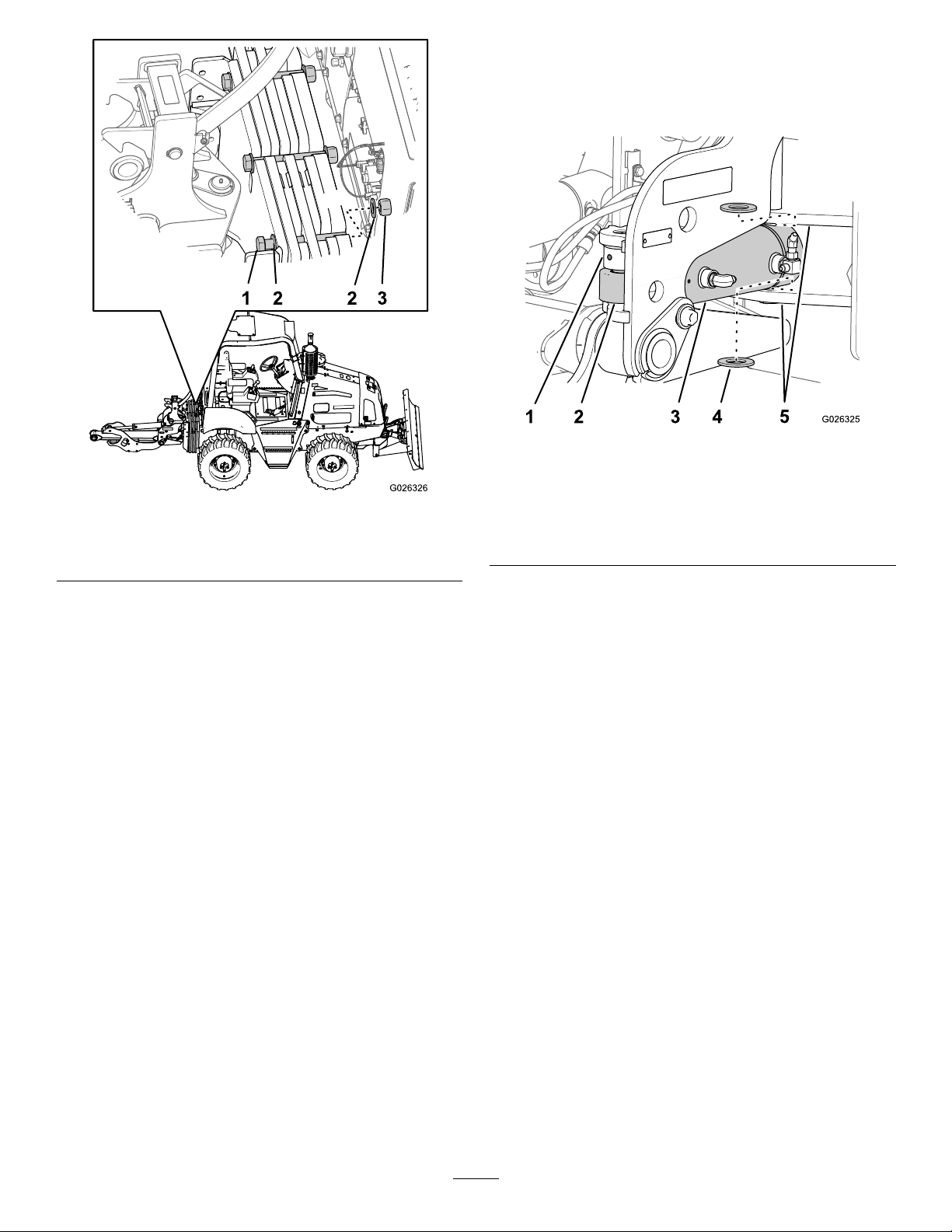
GreasingtheFittings
ServiceInterval:Beforeeachuseordaily
GreaseType:Lithiumbasedgrease
1.Cleanthegreasettingswitharag.
2.Connectthegreaseguntothegreasetting,andapply
3pumpsofgreasetothetting(Figure92,Figure93,
andFigure94).
3.Wipeupanyexcessgrease.
Figure92
Figure93
41
Page 42

TorquingtheFastenersonthe ShakerBox
ServiceInterval:Aftertherst5hours
Every40hours
Torquetheboltsandnutsontheshakerboxto183to203
N-m(135to150ft-lb)inthepatternshowninFigure95.
Figure94
1.Greasettings(left-andright-swingcylinder)
Figure95
Topviewshownintheinset
42
Page 43

Storage
1.Beforestoringthetractionunit,brushoffthedirtfrom
theattachment.
Note:RefertothetractionunitOperator’sManualfor
storingthetractionunit.
2.Checktheconditionofthehoses,thestabilizershoes,
theplowblade,andthecablechute.Replaceanyworn
ordamagedparts.
3.Checkandtightenallbolts,nuts,andscrews.Repairor
replaceanypartthatisdamagedorworn.
4.Ensurethatallhydrauliccouplersareconnected
togethertopreventcontaminatingthehydraulicsystem.
5.Paintallscratchedorbaremetalsurfaceswithpaint
availablefromanAuthorizedServiceDealer.
6.Storetheattachmentinaclean,drygarageorstorage
area.Coverthevibratoryplowtoprotectitandkeepit
clean.
43
Page 44

Troubleshooting
Problem
Theplowdoesnotvibrate.
Thebladedoesnotplowfastenough.
PossibleCauseCorrectiveAction
1.Ahydraulicttingisnotcompletely
connected.
2.Ahydraulicttingisdamaged.2.Replacethedamagedtting.
3.Thereisanobstructioninahydraulic
hose.
4.Thedrive-controlcableisdisconnected
orhasfailed.
5.Thehydraulicmotorhasfailed.5.ContactanAuthorizedServiceDealer.
6.Thehydraulicpumphasfailed.6.ContactanAuthorizedServiceDealer.
1.Thereisarestrictioninahydraulic
hose.
2.Thehydraulicsystemistoohot.
3.Thereliefvalveissetbelow
specications.
4.Therunningspeed(rpm)oftheengine
istoolow.
5.Theplowspeed(rpm)isnotatthe
maximumlevel.
1.Checkandtightenallttings.
3.Findandremovetheobstruction.
4.Connect,repair,orreplacethe
drive-controlcable.
1.Checkthehosesandrepairany
problemsfound.
2.Shutdownthesystemandallowitto
cool.
3.ContactanAuthorizedServiceDealer.
4.Increasethethrottlesettingorreduce
thedrive-speedsettingtoallowthe
enginetorecovertoitspeaklevelof
power.
5.Increaseordecreasetheattachment
speed(rpm)tomaximizethedrive
speed.
44
Page 45

Notes:
45
Page 46

Notes:
46
Page 47

Notes:
47
Page 48

TheToroUndergroundWarranty
ALimitedWarranty
Underground
Equipment
ConditionsandProductsCovered
TheToroCompanyanditsafliate,ToroWarrantyCompany,pursuant
toanagreementbetweenthem,jointlywarrantyourToroUnderground
Equipment(“Product”)tobefreefromdefectsinmaterialsorworkmanship.
Whereawarrantableconditionexists,wewillrepairtheProduct
atnocosttoyouincludingdiagnostics,labor,andparts.
ThefollowingwarrantyappliesfromthedatetheProductisdeliveredtothe
originalretailpurchaserorrentalowner.
ProductsWarrantyPeriod
RT600,RT1200,DD2024,and
DD4045
AllOtherEnginePoweredBase
UnitsandFluidMixers
AllSerializedAttachments
RockHammer6months
Engines
2yearsor1500operatinghours,
whicheveroccursrst
1yearor1000operatinghours,
whicheveroccursrst
1year
Throughenginemanufacturers:
2yearsor2000operatinghours,
whicheveroccursrst
InstructionsforObtainingWarrantyService
YouareresponsiblefornotifyingtheUndergroundDealerfromwhomyou
purchasedtheProductassoonasyoubelieveawarrantablecondition
exists.IfyouneedhelplocatingaUndergroundDealer ,orifyouhave
questionsregardingyourwarrantyrightsorresponsibilities,youmay
contactusat:
ToroCustomerCare
ToroWarrantyCompany
811 1LyndaleAvenueSouth
Bloomington,MN55420-1196
TollFreeat855-493-0088(U.S.Customers)
1-952-948-4318(InternationalCustomers)
OwnerResponsibilities
AstheProductowner,youareresponsibleforrequiredmaintenanceand
adjustmentsstatedinyourOperator'sManual.Failuretoperformrequired
maintenanceandadjustmentscanbegroundsfordisallowingawarranty
claim.
ItemsandConditionsNotCovered
Notallproductfailuresormalfunctionsthatoccurduringthewarranty
periodaredefectsinmaterialsorworkmanship.Thiswarrantydoesnot
coverthefollowing:
•Productfailureswhichresultfromtheuseofnon-T ororeplacement
parts,orfrominstallationanduseofadd-on,ormodiednon-Toro
brandedaccessoriesandproducts.Aseparatewarrantymaybe
providedbythemanufactureroftheseitems.
•Productfailureswhichresultfromfailuretoperformrecommended
maintenanceand/oradjustments.Failuretoproperlymaintainyour
ToroproductpertheRecommendedMaintenancelistedinthe
Operator’sManualcanresultinclaimsforwarrantybeingdenied.
•ProductfailureswhichresultfromoperatingtheProductinanabusive,
negligent,orrecklessmanner.
•Partssubjecttoconsumptionthroughuseunlessfoundtobedefective.
Examplesofpartswhichareconsumed,orusedup,duringnormal
Productoperationinclude,butarenotlimitedto:brakes,lters,lights,
bulbs,belts,tracksortires,diggingteeth,diggingbooms,digging,
drive,ortrackchains,trackpads,drivesprockets,idlers,rollers,
blades,cuttingedges,orothergroundengagingcomponents.
•Failurescausedbyoutsideinuence.Conditionsconsideredtobe
outsideinuenceinclude,butarenotlimitedto,weather,storage
practices,contamination,useofunapprovedfuels,coolants,lubricants,
additives,water,orchemicals,etc.
•Failureorperformanceissuesduetotheuseoffuels(e.g.gasoline,
diesel,orbiodiesel)thatdonotconformtotheirrespectiveindustry
standards.
•Normalnoise,vibration,wearandtear ,anddeterioration.
•Normal“wearandtear”includes,butisnotlimitedto,damagetoseats
duetowearorabrasion,wornpaintedsurfaces,scratcheddecals,etc.
•Haulingexpenses,traveltime,mileage,orovertimeassociatedwith
transportingproducttotheauthorizedT orodealer .
Parts
Partsscheduledforreplacementasrequiredmaintenanceinthe
Operator’sManual,arewarrantedfortheperiodoftimeuptothescheduled
replacementtimeforthatpart.Partsreplacedunderthiswarrantyare
coveredforthedurationoftheoriginalproductwarrantyandbecomethe
propertyofT oro.Torowillmakethenaldecisionwhethertorepairany
existingpartorassemblyorreplaceit.Toromayuseremanufacturedparts
forwarrantyrepairs.
MaintenanceisatOwner’sExpense
Enginetune-up,lubrication,cleaningandpolishing,replacementoflters,
coolant,andcompletingrecommendedmaintenancearesomeofthe
normalservicesT oroproductsrequirethatareattheowner’sexpense.
GeneralConditions
RepairbyanAuthorizedToroUndergroundDealerisyoursoleremedy
underthiswarranty.
NeitherTheToroCompanynorToroWarrantyCompanyisliablefor
indirect,incidentalorconsequentialdamagesinconnectionwiththe
useoftheToroProductscoveredbythiswarranty,includingany
costorexpenseofprovidingsubstituteequipmentorserviceduring
reasonableperiodsofmalfunctionornon-usependingcompletion
ofrepairsunderthiswarranty.ExceptfortheEmissionswarranty
referencedbelow,ifapplicable,thereisnootherexpresswarranty.All
impliedwarrantiesofmerchantabilityandtnessforusearelimitedto
thedurationofthisexpresswarranty.
Somestatesdonotallowexclusionsofincidentalorconsequential
damages,orlimitationsonhowlonganimpliedwarrantylasts,sotheabove
exclusionsandlimitationsmaynotapplytoyou.Thiswarrantygivesyou
speciclegalrights,andyoumayalsohaveotherrightswhichvaryfrom
statetostate.
Noteregardingenginewarranty:
TheEmissionsControlSystemonyourProductmaybecoveredby
aseparatewarrantymeetingrequirementsestablishedbytheU.S.
EnvironmentalProtectionAgency(EP A)and/ortheCaliforniaAirResources
Board(CARB).Thehourlimitationssetforthabovedonotapplytothe
EmissionsControlSystemWarranty.RefertotheEngineEmissionControl
WarrantyStatementsuppliedwithyourproductorcontainedintheengine
manufacturer’sdocumentationfordetails.
CountriesOtherthantheUnitedStatesorCanada
CustomerswhohavepurchasedT oroproductsexportedfromtheUnitedStatesorCanadashouldcontacttheirT oroDistributor(Dealer)toobtain
guaranteepoliciesforyourcountry ,province,orstate.IfforanyreasonyouaredissatisedwithyourUndergroundDealer’sserviceorhavedifculty
obtainingguaranteeinformation,contacttheToroimporter.
AustralianConsumerLaw:AustraliancustomerswillnddetailsrelatingtotheAustralianConsumerLaweitherinsidetheboxoratyourlocalT oro
Dealer.
374-0292RevA
 Loading...