

Page 1
Installation
LooseParts
FormNo.3378-106RevA
TrackKit
RT1200Trencher
ModelNo.25462—SerialNo.315000001andUp
ModelNo.25462E—SerialNo.315000001andUp
InstallationInstructions
WARNING
CALIFORNIA
Proposition65Warning
ThisproductcontainsachemicalorchemicalsknowntotheStateofCaliforniato
causecancer,birthdefects,orreproductiveharm.
Usethechartbelowtoverifythatallpartshavebeenshipped.
ProcedureDescription
1
2
3
Nopartsrequired
Greasetting(90°elbow)
Pipe4
Coupler
Greasetting
Kingpin4
Bolt(socket-head)—M14—2.00x40
mm,Class12.9
Frame-mountbracket(frontleftorrear
right)
Frame-mountbracket(frontrightorrear
left)
Bolt(M16—2.00x70mm)
Jamnut(M16)
Locknut(M16)
Bolt(M14—2.00x30mm,Class10.9)
Bolt(M14—2.00x60mm,Class10.9)
Lockwasher(M14)
Directionbracket4
Bolt(M12—1.75x60mm,Class8.8)
Flatwasher(M12)
Locknut(M12—1.75,Class8.8)
Hexnut(M16—2.00,Class8.8)
Qty.
16
16
Use
–
4
4
4
4
2
2
8
8
8
8
8
8
8
4
Preparethemachine.
Installthebottomkingpin.
Installtheframe-mountbracket.
©2015—TheToro®Company
8111LyndaleAvenueSouth
Bloomington,MN55420
Registeratwww.Toro.com.
OriginalInstructions(EN)
PrintedintheUSA
AllRightsReserved
*3378-106*A
Page 2

ProcedureDescription
4
Topmountingplate4
Bolt(M14—2.00x40mm,Class10.9)
Jamnut(M14—2.00,Class10.9)
Bolt(M16—2.00x50mm)
Lockwasher(M16)
Shimplate
Bolt(M14—2.00x60mm,Class10.9)
Flatwasher(M14)
Hexnut(M14—2.00,Class10.9)
Qty.
16
16
20
40
20
Use
8
8
Installthetopmountingbracket.
8
5
6
7
8
9
10
Note:Determinetheleftandrightsidesofthemachinefromthenormaloperatingposition.
Nopartsrequired
Chassisframe
Axle-pivotspacer4
Spacer
Retainingring4
Bolt(M16—2.00x50mm,Class10.9)
Hexnut(M16—2.00,Class10.9)
Sprocketthird
Axlepivot4
Bolt(M16—2.00x40mm,Class10.9)
Washer48
Hexnut(M16—2.00,Class10.9)
Track4
Nopartsrequired
Nopartsrequired
Nopartsrequired
–
4
4
12
12
12
24
24
–
–
–
Torquethefasteners.
Installthechassisframe.
Installthesprocketthirdsandthetrack.
Checkandadjustthetoeofthetracks.
Alignthetracks.
Checkthetensionofthetracks.
1
PreparingtheMachine
NoPartsRequired
Procedure
Note:Determinetheleftandrightsidesofthemachine
fromthenormaloperatingposition.
1.Parkthemachineonahard,levelsurface.
2.Setthefrontandrearwheelssothattheyarestraight
forward.
3.Lowertheattachments,stoptheengine,waitforall
movingpartstostop,andremovethekey.
4.Raisethemachineuntilallthewheelsareoffthe
groundandsupportthemachinewithjackstands.
Note:Usejackstandsratedforyourmachineand
attachment.RefertotheOperator’ sManualforyour
machineandeachattachmenttodeterminethetotal
weight.
5.Removethelugnuts,washers,andwheelsfromthe
machine.
Note:Savethelugnutsandwheels.
6.Measureandrecordthelengthoftheexposedbolton
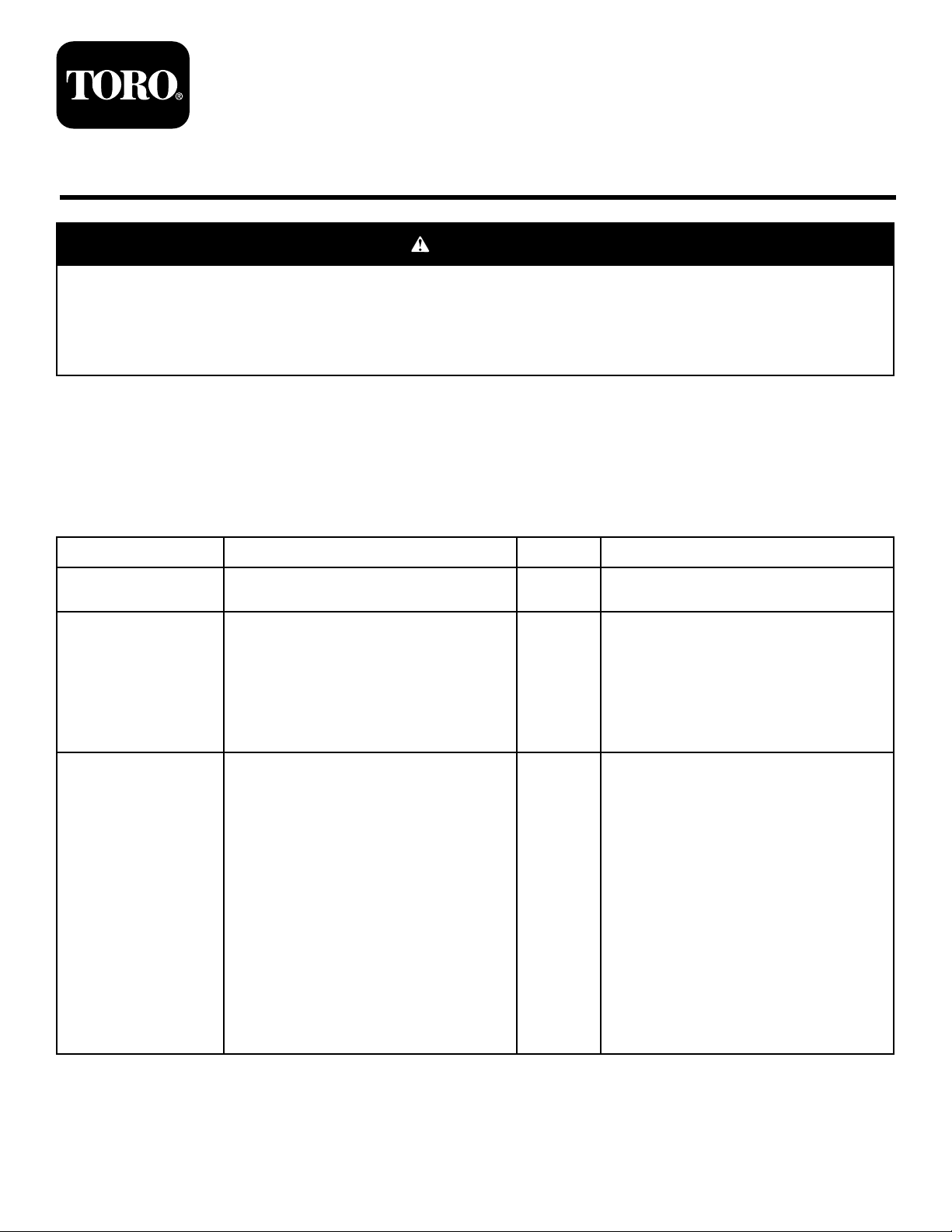
eachsteeringlimiter(Figure1).
Note:Retainthesemeasurementstoinstallthebolt
andnutontoeachsteeringlimiterlater.
2
Page 3
g028884
1
2
3
4
5
Figure1
g0291 10
1
2
3
4
5
6
7
8
9
1.Installa90°elbowgreasetting,apipe,acoupler,and
agreasettingtothebottomkingpin(Figure2).
1.Boltandnut(2)
2.Steeringlimiter
3.Bottomkingpin
7.Removetheboltsandnutsfromthesteeringlimiter
(Figure1).
Note:Savetheboltsandnuts.
8.Supportthewheelhub.
9.Removetheboltsthatholdthebottomkingpinandthe
bottomkingpin(Figure1).
4.Boltssecuringthebottom
kingpin
5.Recordthismeasurement.
1.Hub
2.Kingpin
3.Socket-headbolt
(M14—2.00x40mm,
Class12.9)
4.Holeinkingpinfor
socket-headbolt
5.Holeinkingpinforgrease
ttingassembly
Figure2
6.Greasetting
7.Coupler
8.Pipe
9.90°elbowtting
Note:Savethebottomkingpinandthebolts.
2.Aligntheholesinthebottomkingpin(Figure2)tothe
holesinthehubbylightlyinstalling2bolts(M14—2.00
x30mmor60mm).
2
3.Installthebottomkingpinwithasocket-headbolt
(M14—2.00x40mm,Class12.9)asshowninFigure2.
InstallingtheBottomKingpin
Note:Applyhigh-strength,thread-lockingcompound
tothesocket-headboltbeforeinstallingit.
Partsneededforthisprocedure:
4
Greasetting(90°elbow)
4Pipe
4
Coupler
4
Greasetting
4Kingpin
4
Bolt(socket-head)—M14—2.00x40mm,Class12.9
4.Torquethesocket-headboltto192to234N-m(141
to173ft-lb).
5.Removethe2bolts(M14—2.00x30mmor60mm)
fromthebottomkingpin.
Procedure
Important:Performthisprocedureoneachhub.
3
Page 4

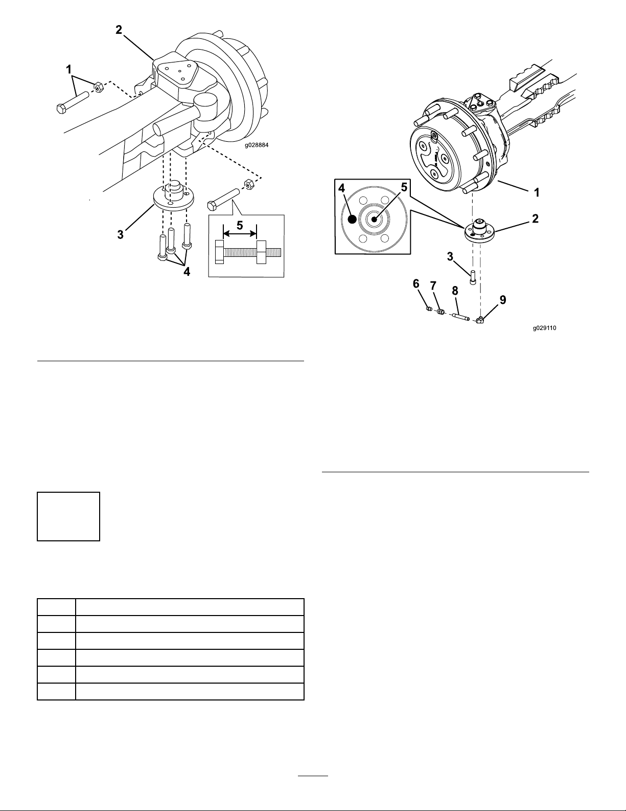
3.Looselyinstalltheframe-mountbracketontothehub
g0291 11
1
2
3
4
6
5
using2bolts(M14—2.00x30mm,Class10.9)and
2bolts(M14—2.00x60mm,Class10.9)upthrough
3
thebottomkingpinand4lockwashersasshownin
Figure4.
InstallingtheFrame-Mount
Bracket
Note:Applyhigh-strength,thread-lockingcompound
totheboltsbeforeinstallingthem.
Partsneededforthisprocedure:
2
Frame-mountbracket(frontleftorrearright)
2
Frame-mountbracket(frontrightorrearleft)
8
Bolt(M16—2.00x70mm)
8
Jamnut(M16)
8
Locknut(M16)
8
Bolt(M14—2.00x30mm,Class10.9)
8
Bolt(M14—2.00x60mm,Class10.9)
16
Lockwasher(M14)
4Directionbracket
8
Bolt(M12—1.75x60mm,Class8.8)
16
Flatwasher(M12)
8
Locknut(M12—1.75,Class8.8)
4
Hexnut(M16—2.00,Class8.8)
Procedure
Important:Performthisprocedureoneachhub.
Note:Useaoorjacktoholdtheframe-mount
bracketinplacewhileyouinstallit.
1.Install2bolts(M16—2.00x70mm),2jamnuts(M16),
and2locknuts(M16)intheframe-mountbracketas
showninFigure3.
Figure4
1.Hubandaxle4.Bolt—M14—2.00x60
2.Frame-mountbracket5.Bolt—M14—2.00x30
3.Lockwasher(4)6.Holeinkingpinforbolts(4)
mm,Class10.9(2)
mm,Class10.9(2)
Note:Thereare2typesofframe-mountbrackets,1
bracketforthefront,lefttrackandtherear,righttrack;
andtheotherbracketforthefront,righttrackandthe
Figure3
1.Locknuts(M16)3.Bolts(M16—2.00x70
2.Jamnuts(M16)
2.Torquetheboltsandlocknutsto255to311N-m(188
to230ft-lb).
mm)
rear,lefttrack.
4.Installtheboltsandnutsonthesteeringlimiterthat
youpreviouslyremovedandsetittothemeasurement
thatyoupreviouslyrecordedinstep6of1Preparing
theMachine(page2).
5.Slipadirectionbracket(Figure5)bythetopholeonto
theboltendofthesteeringlimiter.
4
Page 5
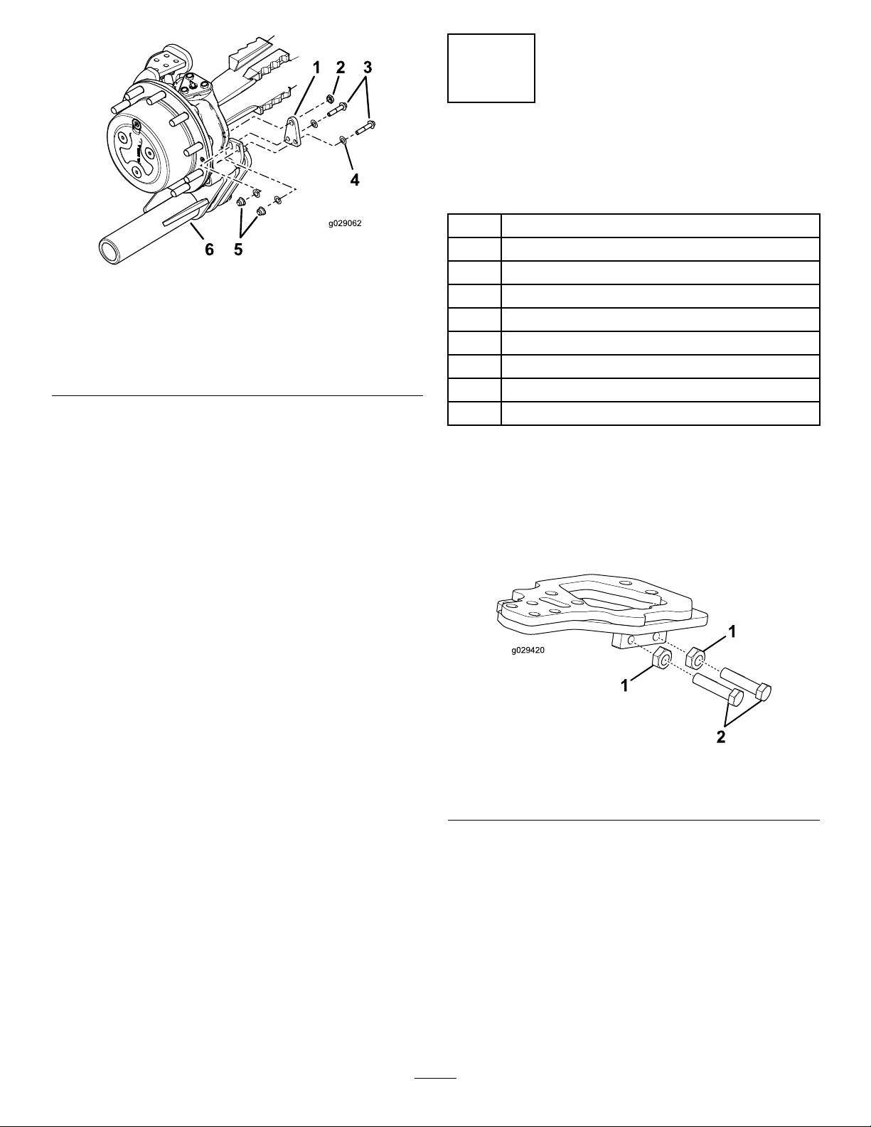
Figure5
1.Directionbracket
2.Hexnut(M16—2.00,
Class8.8)
3.Bolts(M12—1.75x60
mm,Class8.8)
4.Flatwasher—M12(4)
5.Locknuts(M12—1.75,
Class8.8)
6.Tube
6.Installthedirectionbracketontotheframe-mount
bracketwith2bolts(M12—1.75x60mm,Class8.8)
and2locknuts(M12—1.75,Class8.8)inthelower
holes;installahexnut(M16,Class8.8)attheupper
holeasshowninFigure5.
7.Torquethe2bolts(M12—1.75x60mm,Class8.8)
and2locknuts(M12—1.75,Class8.8)to70to86N-m
(52to63ft-lb).
8.Torquethehexnut(M16,Class8.8)attheupperhole
to255to311N-m(188to230ft-lb).
4
InstallingtheTopMounting
Bracket
Partsneededforthisprocedure:
4Topmountingplate
8
Bolt(M14—2.00x40mm,Class10.9)
8
Jamnut(M14—2.00,Class10.9)
16
Bolt(M16—2.00x50mm)
16
Lockwasher(M16)
8
Shimplate
20
Bolt(M14—2.00x60mm,Class10.9)
40
Flatwasher(M14)
20
Hexnut(M14—2.00,Class10.9)
Procedure
Important:Performthisprocedureoneachhub.
1.Installthe2bolts(M14,Class10.9)and2jamnuts
(M14,Class10.9)ontothetopmountingplateas
showninFigure6.
Figure6
1.Jamnuts(M14,Class
10.9)
2.Bolts(M14—2.00x40
mm,Class10.9)
2.Torquetheboltsandjamnutsto192to234N-m(141
to173ft-lb).
3.Looselyinstallthetopmountingplatetothe
frame-mountbracketusing4bolts(M16–2.00x50
mm,Class10.9)and4lockwashers(M16)asshown
inFigure7.
Note:Ensurethattheboltsaretightbutnottorqued
tothespecication.
5
Page 6

5
TorquingtheFasteners
NoPartsRequired
Procedure
Important:Performthisprocedureoneachhub.
1.Tightenallthehardwarefromthepreviousstepsexcept
forthedirectionbracket(step6).
•Torquethe2bolts(M14—2.00x30mm,Class
10.9)and2bolts(M14—2.00x60mm,Class10.9)
thatsecuretheframe-mountbracket(refertostep
3of3InstallingtheFrame-MountBracket(page
3))to164to200N-m(121to147ft-lb).
•Torquethe4bolts(M16—2.00x50mm,Class
10.9)thatsecurethetopmountingplate(step3of
4InstallingtheTopMountingBracket(page5))to
255to311N-m(188to230ft-lb).
•Torquethe5bolts(M14—2.00x60mm,Class
10.9)and5hexnuts(M14,Class10.9)thatsecure
theshimsandtopmountingplate(step6of4
InstallingtheTopMountingBracket(page5))to
192to234N-m(141to173ft-lb).
Figure7
1.Bolt—M16—2.00x50
mm,Class10.9(4)
2.Lockwasher—M16(4)7.Greasettingontop
3.Bolt—M14—2.00x60
mm,Class10.9(5)
4.Flatwasher—M14(5)9.Flatwasher—M14(5)
5.Topmountingplate
4.Determinehowmanyshimplatesthatyouneedinthe
locationshowninFigure7.
5.Aligntheholesintheshimplateswiththeholesinthe
topmountingplate.
6.Looselyinstallthemountingplateandshimplates
with5bolts(M14—2.00x60mm,Class10.9),10at
washers(M14),and5hexnuts(M14,Class10.9);refer
toFigure7.
7.Adjustthetubesothatitisperpendiculartothe
mountingfaceofthedrivehub(Figure7).
6.Shimplates(useas
needed)
kingpin
8.Frame-mountbracket
10.Hexnut—M14,Class10.9
(5)
2.Removeanddiscardthestraightgreasettingonthe
topkingpin(Figure7)andreplaceitwitha90°grease
tting.
6
InstallingtheChassisFrame
Partsneededforthisprocedure:
4
Chassisframe
4Axle-pivotspacer
4
Spacer
4Retainingring
12
Bolt(M16—2.00x50mm,Class10.9)
12
Hexnut(M16—2.00,Class10.9)
Procedure
Important:Performthisprocedureoneachhub.
1.Positionthechassisframesothatthetrackadjusters
arelocatedawayfromthecenterofthemachineas
showninFigure8andFigure9.
6
Page 7

Note:Figure8andFigure9showonlytheoutertrack
adjusters;theinnertrackadjustersarenotshown.
Note:Ensurethatthegreasettingsonthechassis
framefaceoutward.
Figure11
Nut—M16—2.00,Class10.9(3)notshown
Figure8
Forthefront,lefttrackandtherear,righttrack
1.Outertrackadjuster(2)
Figure9
Forthefront,righttrackandtherear,lefttrack
1.Outertrackadjuster(2)
2.Turnboththeinnerandoutertrack-adjusterbolts
(Figure10)sothattheadjustersmoveinward,making
iteasiertoinstallthetracklater.
1.Bolt—M16—2.0x50mm,
Class10.9(3)
2.Axlepivot
3.Chassisframe
4.Tubeoftheframe-mount
bracket
4.Insertanaxle-pivot(at)spacerbetweenthe
frame-mountbracketandthechassisframeandthe
spacer(Figure11).
5.Installtheretainingringonoutsideoftrack-chassis
frame,andsecuretheaxlepivotwith3bolts(M16—2.0
x50mm,Class10.9)and3nuts(M16—2.00,Class
10.9).
Note:Torquethe3boltsand3nutsto255to311
N-m(188to230ft-lb).
6.Repeatthisprocedurefortheremaining3tracks.
5.Axle-pivotspacer(at)
6.Spacer
7.Retainingring
7
Figure10
Onlytheoutertrackeradjusterisshown.
1.Track-adjusterbolt(2)
3.Installthechassisframetotheframe-mountbracket
usingtheaxlepivot(Figure11).
Note:Useahoisttoliftandpositionthechassisframe.
InstallingtheSprocketThirds
andtheTrack
Partsneededforthisprocedure:
12
Sprocketthird
4Axlepivot
24
Bolt(M16—2.00x40mm,Class10.9)
48Washer
24
Hexnut(M16—2.00,Class10.9)
4Track
Procedure
Important:Performthisprocedureoneachhub.
1.Alignthe3sprocketthirdstogetherontheoor
(Figure12).
Note:Thisisanecessarystepbecausethesprocket
thirdsarenotsymmetricalandthereforettogether
only1way.
7
Page 8

Figure12
2.Assembleasprocketthirdontothewheellugsand
looselyinstallthelugnuts(Figure13).
7.Securethesprocketstogetherusing6setsoffasteners
thatconsistofabolt(M16—2.00x40mm,Class10.9),
2washers,andahexnut(M16—2.00,Class10.9)each
(Figure14).
Note:Torquetheboltsandnutsto255to311N-m
(188to230ft-lb).
Figure14
Thenalsprocketthirdisnotshownforthepurposeof
clarity.
Figure13
1.Nut3.Wheellug
2.Sprocketthird
Note:Itiseasiertoslidethesprocketthirdbetween
themaintubeandthetrack-adjustermechanism.
3.Installthetrackoverthesprocketsandunderthe
chassisframe.
Note:Notetheorientationofthetrackpattern.To
makeinstallingthetrackeasier,applysoapywateror
mineraloiltotheteethofthetrack.
1.Spocketthird4.Nut(M16—2.00,Class
2.Bolt(M16—2.00x40mm,
Class10.9)
3.Washers
10.9)
5.Onesetoffasteners—bolt
(1),washers(2),andnut
(1)
8.Turnboththeinnerandoutertrack-adjusterbolts
outward(Figure15)thesameamountsothatthe
tensionacrossthetrackisequalwhileyousecurethe
trackinplace.
Note:Usingahoisttoliftthetrackmakesinstalling
iteasier.
4.Startthemachineandrotatethesprocketthirdtothe
topposition.
5.Assembleanothersprocketthird,rotateittotheside
position,andlooselyinstallthelugnuts.
6.Assemblethenalsprocketthirdandlooselyinstall
thelugnuts.
Figure15
1.Trackadjusterbolt(2)
2.Movethetrackadjuster
boltsevenlyoutward
9.Repeatthisprocedurefortheremaining3tracks.
8
Page 9

8
g029074
1
2
3
4
1
2
3
g028918
9
CheckingandAdjustingthe
ToeoftheTracks
NoPartsRequired
Procedure
Important:Performthisprocedureoneachhub.
Note:Checktoensurethatthecenterlinesthetracksoneach
axleareapproximatelyparallel,withouttoe-inortoe-out.If
theyarenot,performtheprocedurethatfollows.
1.Placeawrenchontheatsurfacesonthetie-rodend
(Figure16).
AligningtheTracks
NoPartsRequired
Procedure
Important:Performthisprocedureoneachhub.
Todeterminewhetherthetracksarecorrectlyaligned,start
theengine,rotatethetrackatleast6times,andcheckwhether
thewheelsremaincenteredbetweentheteethofthetrack
(Figure17).
Note:Thewheelsshouldremaincenteredbetweentheteeth
ofthetrack.
Figure16
1.Threadedadjuster3.Holdawrenchhereonthe
2.Jamnut
2.Useasecondwrenchtoloosenthejamnut(Figure16).
3.Movethesecondwrenchtotheatsurfacesofthe
threadedadjuster(Figure16)androtatethethreaded
adjusterinwardoroutwarduntilthetracksare
approximatelyparallel.
Note:Rotatethethreadedadjusterclockwiseto
shortenit;rotateitcounterclockwisetolengthenit.
4.Withtherstwrenchstillinplace,tightenthejamnut
securely.
5.Adjustthesteeringlimiter(Figure16)asneededto
preventthetrackfrominterferingwiththemachine.
6.Lowerthemachinetotheground.
tierodend.
4.Steeringlimiter
Figure17
1.Trackmigration3.Wheels
2.Teeth
Ifthetrackbeginstomigrateoffthewheels,increasethe
tensiononthesideofthetrackwhereittendstomigrate
(Figure18)usingthefollowingprocedure:
9
Page 10

5
1
2
3
4
g028917
6
Figure18
Backviewoftrack
1.Directionoftrackmigration4.Outsidetrackadjuster
2.Exteriorside5.Insidetrackadjuster
3.Interiorside6.Track
1.Movethetrackadjusteronthesidewherethetrackis
migratingoffthewheelsbyturningthetrack-adjuster
boltoutward6mm(1/4inch);refertoFigure19.
3.Repeatthisprocedureuntilthewheelsremaincentered
betweentheteethofthetrack.
10
CheckingtheTensionofthe
Tracks
NoPartsRequired
Procedure
Important:Performthisprocedureoneachhub.
Important:Itisnormalforthetrackstostretchthe
rsttimethatyouusethem.Adjustthetensionofthe
tracksaftertherst25operatinghourstopreventthe
componentsfromwearingprematurely.Improperly
tensionedtrackscanleadtoprematurewearingorloss
oftrackcomponents.Checkthetensionofthetracks
regularly.
TrackTension
ToolooseThetrack
TootightThetracklosesa
Signs
disengagesinthe
tractionteethofthe
sprocketwheel.
Thereisa
signicantincrease
invibration.
signicantamount
ofpowerand
revolutionspeed.
Possible
Consequences
Thetrackteeth
wearprematurely.
Thetrack
losestraction.
Thereisarisk
ofthetrackcoming
off.
Thetrack,ball
bearings,sprocket
wheelstems,
andplanetary
gearboxallwear
prematurely.
1.Raisethemachineandpositionithorizontally.
2.Rotatethetracksothatthemodel/serialnumberplate
ofthetrackisbetweenthesmallerwheels.
3.Puta45kg(100lb)roundbarintothetrackbetween
thelugsandbetweenthe2smallerwheels.
Figure19
Sideviewoftrack
Note:Asteelbar6.35cm(2-1/2inches)indiameter
and183cm(72inches)longwillwork.
1.Track-adjusterbolt(2)
2.Movethetrackadjuster
outward6mm(1/4inch)
4.Measurethedistance(gap)betweentheinnersurface
ofthetrackandthetrackbeam(Figure20).
2.Starttheengine,rotatethetrackatleast6times,and
checkwhetherthewheelsremaincenteredbetween
theteethofthetrack.
Note:Ifthetrackisalreadystretchedtoitsmaximum,
reducethetensionby6mm(1/4inch)ontheinner
trackadjuster.
10
Page 11

g028915
1
2
Figure20
1.Gap—83to89mm(3-1/4
to3-1/2inches)
2.Roundbar
5.Repeatthismeasurement5pitchesaheadand5pitches
afterthelocationofthemodel/serialnumberplate.
Note:Rotatethetracksothatallthesepositionsare
locatedbetweenthe2smallerwheels.
Note:Themaximumallowabledistanceshouldbe
within83to89mm(3-1/4to3-1/2inches)fromthe
trackinnersurfaceandthetrackbeam.
6.Adjusttheadjustersforthetrackasneeded.
7.Lowerthemachinetotheground.
11
Page 12

12
Page 13

Notes:
13
Page 14

Notes:
14
Page 15

Notes:
15
Page 16

ToroGeneralCommercialProductWarranty
ATwo-YearLimitedWarranty
ConditionsandProductsCovered
TheT oroCompanyanditsafliate,T oroWarrantyCompany,pursuant
toanagreementbetweenthem,jointlywarrantyourT oroCommercial
product(“Product”)tobefreefromdefectsinmaterialsorworkmanship
fortwoyearsor1500operationalhours*,whicheveroccursrst.This
warrantyisapplicabletoallproductswiththeexceptionofAerators
(refertoseparatewarrantystatementsfortheseproducts).Wherea
warrantableconditionexists,wewillrepairtheProductatnocosttoyou
includingdiagnostics,labor,parts,andtransportation.Thiswarranty
beginsonthedatetheProductisdeliveredtotheoriginalretailpurchaser .
*Productequippedwithanhourmeter .
InstructionsforObtainingWarrantyService
YouareresponsiblefornotifyingtheCommercialProductsDistributoror
AuthorizedCommercialProductsDealerfromwhomyoupurchasedthe
Productassoonasyoubelieveawarrantableconditionexists.Ifyouneed
helplocatingaCommercialProductsDistributororAuthorizedDealer,or
ifyouhavequestionsregardingyourwarrantyrightsorresponsibilities,
youmaycontactusat:
ToroCommercialProductsServiceDepartment
ToroWarrantyCompany
811 1LyndaleAvenueSouth
Bloomington,MN55420-1196
952–888–8801or800–952–2740
E-mail:commercial.warranty@toro.com
OwnerResponsibilities
AstheProductowner ,youareresponsibleforrequiredmaintenanceand
adjustmentsstatedinyourOperator'sManual.Failuretoperformrequired
maintenanceandadjustmentscanbegroundsfordisallowingawarranty
claim.
ItemsandConditionsNotCovered
Notallproductfailuresormalfunctionsthatoccurduringthewarranty
periodaredefectsinmaterialsorworkmanship.Thiswarrantydoesnot
coverthefollowing:
•Productfailureswhichresultfromtheuseofnon-T ororeplacement
parts,orfrominstallationanduseofadd-on,ormodiednon-T oro
brandedaccessoriesandproducts.Aseparatewarrantymaybe
providedbythemanufactureroftheseitems.
•Productfailureswhichresultfromfailuretoperformrecommended
maintenanceand/oradjustments.Failuretoproperlymaintainyour
ToroproductpertheRecommendedMaintenancelistedinthe
Operator’sManualcanresultinclaimsforwarrantybeingdenied.
•ProductfailureswhichresultfromoperatingtheProductinanabusive,
negligent,orrecklessmanner.
•Partssubjecttoconsumptionthroughuseunlessfoundtobedefective.
Examplesofpartswhichareconsumed,orusedup,duringnormal
Productoperationinclude,butarenotlimitedto,brakepadsand
linings,clutchlinings,blades,reels,rollersandbearings(sealedor
greasable),bedknives,sparkplugs,castorwheelsandbearings,tires,
lters,belts,andcertainsprayercomponentssuchasdiaphragms,
nozzles,andcheckvalves,etc.
•Failurescausedbyoutsideinuence.Conditionsconsideredtobe
outsideinuenceinclude,butarenotlimitedto,weather,storage
practices,contamination,useofunapprovedfuels,coolants,lubricants,
additives,fertilizers,water,orchemicals,etc.
•Failureorperformanceissuesduetotheuseoffuels(e.g.gasoline,
diesel,orbiodiesel)thatdonotconformtotheirrespectiveindustry
standards.
•Normalnoise,vibration,wearandtear ,anddeterioration.
•Normal“wearandtear”includes,butisnotlimitedto,damagetoseats
duetowearorabrasion,wornpaintedsurfaces,scratcheddecalsor
windows,etc.
Parts
Partsscheduledforreplacementasrequiredmaintenancearewarranted
fortheperiodoftimeuptothescheduledreplacementtimeforthatpart.
Partsreplacedunderthiswarrantyarecoveredforthedurationofthe
originalproductwarrantyandbecomethepropertyofToro.Torowillmake
thenaldecisionwhethertorepairanyexistingpartorassemblyorreplace
it.Toromayuseremanufacturedpartsforwarrantyrepairs.
DeepCycleandLithium-IonBatteryWarranty:
DeepcycleandLithium-Ionbatterieshaveaspeciedtotalnumberof
kilowatt-hourstheycandeliverduringtheirlifetime.Operating,recharging,
andmaintenancetechniquescanextendorreducetotalbatterylife.Asthe
batteriesinthisproductareconsumed,theamountofusefulworkbetween
chargingintervalswillslowlydecreaseuntilthebatteryiscompletelyworn
out.Replacementofwornoutbatteries,duetonormalconsumption,
istheresponsibilityoftheproductowner.Batteryreplacementmaybe
requiredduringthenormalproductwarrantyperiodatowner’sexpense.
Note:(Lithium-Ionbatteryonly):ALithium-Ionbatteryhasapartonly
proratedwarrantybeginningyear3throughyear5basedonthetime
inserviceandkilowatthoursused.RefertotheOperator'sManualfor
additionalinformation.
MaintenanceisatOwner’sExpense
Enginetune-up,lubrication,cleaningandpolishing,replacementoflters,
coolant,andcompletingrecommendedmaintenancearesomeofthe
normalservicesT oroproductsrequirethatareattheowner’sexpense.
GeneralConditions
RepairbyanAuthorizedToroDistributororDealerisyoursoleremedy
underthiswarranty.
NeitherTheT oroCompanynorToroWarrantyCompanyisliablefor
indirect,incidentalorconsequentialdamagesinconnectionwiththe
useoftheToroProductscoveredbythiswarranty,includingany
costorexpenseofprovidingsubstituteequipmentorserviceduring
reasonableperiodsofmalfunctionornon-usependingcompletion
ofrepairsunderthiswarranty.ExceptfortheEmissionswarranty
referencedbelow,ifapplicable,thereisnootherexpresswarranty.All
impliedwarrantiesofmerchantabilityandtnessforusearelimitedto
thedurationofthisexpresswarranty.
Somestatesdonotallowexclusionsofincidentalorconsequential
damages,orlimitationsonhowlonganimpliedwarrantylasts,sotheabove
exclusionsandlimitationsmaynotapplytoyou.Thiswarrantygivesyou
speciclegalrights,andyoumayalsohaveotherrightswhichvaryfrom
statetostate.
Noteregardingenginewarranty:
TheEmissionsControlSystemonyourProductmaybecoveredby
aseparatewarrantymeetingrequirementsestablishedbytheU.S.
EnvironmentalProtectionAgency(EPA)and/ortheCaliforniaAirResources
Board(CARB).Thehourlimitationssetforthabovedonotapplytothe
EmissionsControlSystemWarranty .RefertotheEngineEmissionControl
WarrantyStatementsuppliedwithyourproductorcontainedintheengine
manufacturer’sdocumentationfordetails
CountriesOtherthantheUnitedStatesorCanada
CustomerswhohavepurchasedT oroproductsexportedfromtheUnitedStatesorCanadashouldcontacttheirToroDistributor(Dealer)toobtain
guaranteepoliciesforyourcountry ,province,orstate.IfforanyreasonyouaredissatisedwithyourDistributor'sserviceorhavedifcultyobtaining
guaranteeinformation,contacttheT oroimporter.
374-0253RevC
 Loading...